Abstract
This paper strives to achieve a comprehensive review of chaos in analog circuits and lumped electronic networks. Readers will be guided from the beginning of the investigations of simple electronic circuits to the current trends in the research into chaos. The author tries to provide the key references related to this issue, including papers describing modern numerical algorithms capable of localizing chaotic and hyperchaotic motion in complex mathematical models, interesting full on-chip implementations of chaotic systems, possible practical applications of entropic signals, fractional-order chaotic systems and chaotic oscillators with mem-elements.
Keywords:
analog computer; circuit synthesis; chaos; chaotic oscillators; hyperchaos; nonlinear dynamics; strange attractors MSC:
37M05
1. Introduction
Chaos belongs to the ancient terms usually connected with a high degree of disorder. However, half a century of intensive research in nonlinear dynamics and chaos theory revealed that there is nothing random behind this phenomenon. If related to lumped electronic circuits, chaos can be considered as a long-term unpredictable behavior of the system, characterized by the time evolution of the circuit quantities that are both extremely sensitive to the initial conditions and bounded in a finite state-space volume. The signals that are generated by the chaotic circuit and form the shape of a typical strange attractor, possess a continuum of the sinusoidal frequency components, such that these chaotic waveforms resemble noise in many aspects.
There are two necessary conditions under which chaos can evolve: three degrees of freedom (valid for autonomous systems; driven systems need to be of at least second order) and the presence of some nonlinearity. Surprisingly, the existence of robust chaos is not restricted to algebraically complicated mathematical models but can be observed within a very simple set of differential equations with six terms, including nonlinearity. In addition, chaotic circuits need not be complex networks having many active elements; a few passives only (including one nonlinear two-terminal device) and one locally active circuit element, can be used. Moreover, chaos is not conditioned by the presence of a strong multidimensional or vector nonlinearity. On the contrary, the majority of published chaos generators contain up to three scalar nonlinearities, while many chaotic cases function with one. Besides the strange attractors that are excited by an unstable equilibrium point, several chaotic systems without equilibrium points have been already described, as well as dynamical systems having equilibrium structures which have degenerated into geometrical objects such as lines, curves, circles, squares, etc. The popular chaotic dynamical systems able to produce multi-grid spiral attractors have fixed points formed into a line, plane, or space, depending on the number of dimensions in which spirals must be generated. In addition to the oldest spiral chaotic attractors, many other geometrical shapes turn out to be possible, such as trumpets, funnels, stars, spikes, etc.
Recently, methods of how to reveal the so-called hidden attractors have been published, i.e., strange attractors with basins of attraction that do not contain these fixed points have been discovered and reported. Dissipative as well as conservative chaotic systems are known at the moment, together with chaotic dynamics that exhibit antimonotonicity, multistability, extreme multistability, time reversibility, and other interesting features. Besides conventional integer-order systems, fractional-order (FO) dynamical systems can exhibit a rich gallery of chaotic attractors as well. By considering FO differential equations, the total mathematical order of the analyzed chaotic system can be decreased below the boundaries mentioned above, without violation of the Poincaré– Bendixson theorem. The higher-order dynamics can be subject to hyperchaos, where flow is locally expanding in several state-space directions. Both isolated and non-autonomous systems (driven by either sinusoidal or pulse-type forces) can behave chaotically, as already proved in many publications.
The main body of this manuscript is divided into four sections, depending on the context in which chaos is involved. The upcoming part investigates published works where standard analog building blocks are mathematically modelled and analyzed, with respect to the evolution of chaos. The third section describes engineering areas where chaos can be used or, in other words, the possible applications of chaotic oscillators are briefly described. The fourth section is focused on the construction of the chaotic oscillator itself. Different approaches are described, and many practical constructions (including the new one) are discussed. The fifth section provides a short list of interesting recent development made in the field of this paper. Finally, the summary of comprehensive works cited in these paper and open topics for future research are discussed.
2. Evolution of Chaos in Electronic Systems
As mentioned above, the study of chaos in lumped electronic circuits represents a mature topic which has been solved by individuals and research teams from around the world for four decades [1,2]. Probably the first circuit where chaos has been confirmed both theoretically and experimentally is the famous Chua’s oscillator [3,4], i.e., a circuit named after its inventor, Professor Chua. It can be considered a third-order passive two-terminal element connected in parallel with a nonlinear active resistor. This resistor can have either piecewise linear (PWL) [5,6] polynomial [7] or ampere-voltage (AV) characteristics. Since this key discovery, Chua’s oscillator has becomes paradigm of chaos studies for several decades. Up to now, this simple circuit has undergone intensive investigations from different perspectives, and still serves for educational purposes. It is not only because of its circuit simplicity, but especially because of the transparent mechanism that is responsible for chaotic self-oscillations. To date, several publications have been devoted to the phenomena which is “behind the scenes”, for example, numerical calculations and a graphical visualization of eigenvalues, eigenspaces and boundary planes [8,9].
This is probably the right place to start our sightseeing journey across the lumped analog chaotic networks.
2.1. Canonical Realizations of Chaos Generators
The development of Chua’s circuit initiated instant and enormous interest of researchers and engineers in the design of chaotic oscillators. Let us repeat that this oscillator consists of linear third-order admittance with four passive elements and an active two-terminal device. This device is usually implemented by a negative resistor in parallel with two antiparallel diodes, each in series with a resistor and DC voltage source, or alternatively, with a parallel connection of two negative resistors with different breakpoints of the AV curve. This creates a five-segment PWL AV curve with a negative slope in three inner segments. This nice idea is followed in the design process of many other generators of chaos. For example, the author in [10] succeeded in the interchange of inductor–resistor–capacitor third-order admittance with resistor–capacitor admittance of the same order. Doing so, the linear part of the investigated system is formed by a ladder of RC elements (three sections) leading to low-pass-like immittance function. Chaos can be observed for the negative slope of the PWL resistor in the inner segment of the AV curve and positive (passive) slopes in both outer segments of the AV curve. As a typical strange attractor produced by Chua’s oscillator is denoted as a double scroll, the chaotic attractor generated by the RC ladder structure is called a dual double scroll, because of inversed stability indexes associated with all fixed points of the system.
The synthesis of an electronic circuit based on the prescribed mathematical model is a task which has many correct solutions, and the process of choosing the optimal one can be guided by many criteria [11]. On the other hand, there is always a tendency to generalize existing results and provide a systematic design methodology that surely leads to success. A very interesting paper [12] introduces a universal approach dedicated to circuit design of the chaotic system with PWL nonlinearity. The input parameters are eigenvalues associated with individual segments of the vector field. Although the presence of such elements is mandatory, the author’s main contribution is to minimize the amount of negative circuit elements, in particular resistors with a negative slope of the AV curve. The authors in paper [13] provide an extension of these results to the higher order PWL chaotic circuits. A comparison of the coefficients of the characteristic polynomial associated with the circuit’s individual affine segments with prescribed values (defined by known eigenvalues), provides design rules for circuit components, including value limitations.
The closed loop of the low-pass passive filter working in the trans-resistance mode and the two-port with trans-admittance-type polynomial input–output characteristic of quadratic form, is suggested in paper [14]. Circuitry realizations proposed in this manuscript really belong to the simplest ones from a construction and verification point of view. Final chaotic oscillators require only a single active, and five passive, components. A very good agreement between chaotic attractors obtained by the numerical integration process, computer-aided circuit simulation, and true experimental measurement has been confirmed.
In previous cases of chaotic electronic systems, both the fundamental properties necessary for the genesis of chaos (nonlinearity and the presence of an active element) were implemented in one functional block. The chaotic circuit proposed by the authors in work [15] has a different structure. Nonlinearity of a vector field is achieved by the general-purpose diode, while a frequency dependent negative resistor (FDNR) is the only active two-terminal element. The internal structure of this FDNR is irrelevant, as long as it can be considered as the ideal element. Therefore, two active elements are required for the design of a grounded FDNR.
The utilization of a unity-gain voltage amplifier, a common diode, and an adjustable current source for the construction of a simple third-order chaotic oscillator is proposed in paper [16]. In fact, describing a mathematical model can be considered as a jerk function here, as it is a single third-order ordinary differential equation.
Because of their oscillating nature, generators of chaotic waveforms can be derived directly from conventional second-order sinusoidal oscillators. The specific internal structure of this harmonic part is not important. Robust chaos can be obtained by placing either a diode-inductor [17] or FET-capacitor [18] composite in proper places inside a feedback path. In these papers, the authors demonstrate the validity of their approach using a cascade of two lossless integrators and Wien bridge topology as sources of sinusoidal waveforms. Experimental results are also included and, due to the single-folded shape of nonlinearity, single spiral chaotic attractors were observed.
2.2. Chaotic Steady-States Detected in Standard Signal Processing Systems
Complex analog systems can usually be divided into simpler functional parts. These can be modeled and analyzed separately, with the predefined interaction between these objects. Besides the chaos made by the deliberate modification of the circuit, chaotic steady states can be observed in the original system by considering some non-ideal or parasitic properties of the active element. Of course, the boundary between willing modification and unfortunate parasitics is very thin, sometimes depending only on the interpretation of nonlinearity or the purpose of the mathematical model.
As already stated, sinusoidal oscillators can be forced to chaos generation by adding one suitable nonlinear circuit element. In a pioneering paper [19] the author pointed out that chaos can be observed, both numerically and experimentally, within the well-known single transistor-based Colpitts oscillator. The strange attractor observed experimentally is robust, and persists in several types of discrete bipolar transistors. The mathematical description is derived using a simple model of a bipolar transistor considering only two operational states: active and cut-off. Therefore, a two-segment PWL approximation of base-emitter resistance and a linear current-controlled current source placed between a collector–emitter of the transistor is supposed. After many years of waiting, a Colpitts-like chaotic circuit has been deeply numerically analyzed in paper [20]. The only difference between the new and old configuration of the circuit is the intrinsic capacitance of the transistor, which in the new version admitted completing the resonant tank. The two-stage Colpitts oscillator becomes the subject of investigation in paper [21]. Here, the purpose adding a single transistor and capacitor into the classical topology of the Colpitts oscillator is to provide better spectral purity of the sinusoidal signal. The analyzed dynamical system reveals various bifurcation scenarios toward chaotic states, including period-doubling and interior-crisis transition. Hartley’s oscillator can be derived from Colpitts after the bilateral exchange of capacitors and inductors. Chaos in this configuration of a naturally sinusoidal oscillator was confirmed in papers [22,23]. The Clapp oscillator also belongs to this class of oscillators; its basic topology can be obtained if the capacitor is included in series with a feedback inductor. Obviously, the resulting mathematical model will be fourth order, offering the parametric regions leading to the hyperchaotic self-oscillations. In paper [24] the author assumes a generalized transistor modeled as a two-port, described by admittance parameters. Namely, linear input admittance, linear backward trans-conductance and odd-symmetrical cubic polynomial forward trans-conductance is supposed. Clearly, there are some narrow parameter regions where two significantly positive LEs can be recognized. On the other hand, the well-known Pierce oscillator with numerical values of passive circuit components close to the standard operational state probably cannot behave chaotically. The presence of a typical piezoelectrical element in the feedback path will filter out frequency components necessary for a strange attractor to be formed. From this viewpoint of analysis, many similar oscillator structures are still waiting to be investigated (tuned collector, Reinartz, Vackar, etc.).
Sinusoidal RC feedback oscillators can be modified to become generators of chaos even more easily than the previous group of autonomous circuits. As a prototype of the RC feedback oscillator, the popular Wien bridge structure can be adopted. Then, the chaotic oscillator can be obtained by the interchange of the linear and the PWL resistor in the feedback loop. Obviously, there are several cases of such a chaotic circuit, as illustrated in paper [25]. Based on the cited work of Professor Elwakil, chaotic networks presented in survey paper [26] can be considered as bridges between Chua’s oscillator and the Wien bridge RC oscillator. One of the proposed chaotic circuits can be considered as Chua’s oscillator with a synthetic lossy grounded inductor. The other one is the Wien bridge oscillator with grounded inductor-diode composite. PWL nonlinearity can be transformed into a signum function, while the spiral nature of the generated chaotic attractors remains unchanged. This is demonstrated in paper [27], where Wien bridge topology is still used to implement the linear part of the vector field. In fact, inductorless realizations of chaotic oscillators [28] become somehow preferred because of faster practical construction, easier verification, and possible immediate access to all state variables via eth oscilloscope probe. The final example of the chaotic oscillator suitable to be mentioned at this moment is the diode-coupling of two identical phase shift oscillators, each having three RC sections and a single-stage common-emitter transistor-based amplifier. Authors in paper [29] demonstrate that the resulting sixth-order dynamical system exhibits dense chaotic attractors, and the corresponding circuit can be build using only cheap and off-the-shelf components. A very simple chaotic oscillator based on fundamental feedback theory is described and experimentally verified in a brief study [30]. The circuit is composed of a non-inverting amplifier in a direct signal path and frequency selective feedback with a diode as the only nonlinear element. In fact, any type of operational amplifier and diode can be successfully employed. As correctly stated by the authors, the chaos generator is ideal for educational and laboratory purposes. The same count and types of circuit components are used in the chaotic oscillator presented in the framework of paper [31]. However, the design method is different; this topology can be understood as a loop of an ideal inverting integrator and a passive second-order LC integrator. A single diode is connected across this passive two-port element, so that the necessary nonlinearity is provided.
Other good candidates for chaotification are frequency filters and phase correctors. Biquadratic filters are naturally non-autonomous deterministic systems that are typically driven by continuous-time periodic signals. One of the most frequently used configurations of biquad is composed of a cascade connection of the lossless integrators and multi- branch feedback with input summation (the input signal participates as well). This configuration is called the KHN filter, and can behave chaotically for either saturation-type integrators [32] or the nonlinear transfer function of some feedback branches [33]. In both cases, a high quality factor of this filter is required for the evolution of chaos.
Paper [34] probably represents the first comprehensive survey focused on the chaotic behavior observed in phase-locked loops (PLL). This non-autonomous analog functional block normally consists of the phase comparator, the low-pass filter and the voltage-controlled oscillator connected in a loop. From an application point of view, PLL can be used to synchronize signals, input waveform tracking, frequency generation or demodulation. In the latter case, the above-mentioned paper provides explicit expressions that specify the parametric regions that result in chaotic steady states. PLL is considered as a second-order dynamical system, being investigated both numerically and experimentally. Interestingly, robust chaos was detected for physically reasonable parameter values. A qualitative study of bifurcations and chaos in PLL having second-order loop filter is the main topic of paper [35]. The superior dynamical system is autonomous; third-order. with sinusoidal phase-detector characteristics. Another analysis aimed at high-frequency PLL and chaos can be found in study [36]. The increased order of PLL provides a better transient response, but simultaneously causes structural instability and a route-to-chaos scenario of the error signal. Knowledge involving PLL and chaos theory is summed up in review paper [37]. The authors were able to derive a set of nonlinear differential equations that describes PLL. Furthermore, the nonlinear analysis allows the predicting of complex motion, obtaining formulas for lock range, pull-in range and the evolution of chaos.
A multiple-valued static memory cell can be implemented by a pair of properly biased and coupled PWL resonant-tunneling diodes. The high-frequency behavior of each diode can be modeled by additional parasitic accumulation elements, namely lead inductances and shunt capacitances. In so doing, the investigated static-memory model turns into an isolated third-order dynamical system with a PWL vector field with potentially robust chaotic behavior, as demonstrated in paper [38]. Spiral chaotic attractors persist if the PWL AV characteristics of both diodes are approximated by polynomial functions, i.e., functions that are closer to the real situations. Besides a complete numerical analysis of such a case, the author in paper [39] demonstrates the structural stability of the prescribed state attractors by showing experimental verification through the design of flow-equivalent chaotic oscillators. There is a strong reason to believe that multiscrolls, grid scrolls, and similar complex strange attractors can be generated by a properly configured static memory cell, thanks to the very complicated geometric structure of vector fields with repeated segments [40]. In this paper, a triggering control mechanism is introduced into a basic memory system in the form of an ideal current source.
Amplifiers undoubtedly belong to the fundamental parts of electronic systems. From the functional point of view, these blocks should behave like linear two-ports that amplify the input signal to a necessary level without distortion (both linear and nonlinear). However, for high-frequency operations, the transistor needs to be modeled by considering the parasitic terminal capacitances, with values often comparable to the working ones. In addition, high-power and high-efficiency topologies often process relatively large signals, such that the used active element can no longer assumed to be linear. Therefore, the total order of the amplifier can be boosted, so that chaotic transients and steady states become possible behaviors. The author in paper [41] presupposed a generalized bipolar transistor utilized inside a single-stage amplifier with a resonant load. The transistor is modeled as a two-port as described by the admittance parameters, namely linear input admittance, zero output admittance and considering forward and backward trans-conductance as the odd-symmetrical cubic polynomial functions. A class C amplifier, where only backward trans-conductance is considered as a nonlinear scalar function is analyzed in paper [42]. Both polynomial and PWL cases are numerically investigated, and a rich gallery of differently shaped strange attractors were discovered. The structural stability of all the attractors observed numerically was confirmed by experimental verification as well, using the breadboard-based designs. A non-unilateral transistor, but with more realistic properties, namely having linear backward trans-conductance and nonlinear forward trans-conductance, is presumed in paper [43]. In this study, non-integer order accumulation elements approximated by passive ladder two-terminal networks are also included in the numerical analysis. Amplifiers having several transistors are commonly used in the electronic systems dedicated to demanding applications. For example, the cascode stage provides an extension of bandwidth since the Miller effect is compensated by an auxiliary bipolar transistor. The Darlington pair of transistors is suitable in the situations where a high- current amplification factor is needed. Both mentioned types of interconnections of two bipolar transistors loaded by a parallel resonant tank are analyzed in paper [44].
Chaos in power electronic systems is a well-established topic, popular among analog design engineers. Results promulgated in many publications imply that chaos is a common phenomenon in power converters with feedback. Therefore, we can mention some interesting papers dealing with this problem. The first paper to be cited is [45], where the authors derive difference equations to calculate output current, and switching instances are controlled by a pulse-width modulated signal. It is shown that the analyzed discrete system exhibits a zigzag-like return map, noisy bifurcations, and chaos. A similar approach to quantifying the behavior of a current-mode controlled DC-DC convertor including stability criterion is given in the brief study [46]. More detailed work focused on bifurcations and chaos in DC-DC converters can be found in [47]. The authors were able to obtain analytical formulas for the occurrence of periodic orbits and flip bifurcations in switching maps. Sudden jumps to the chaotic operation are explained, and these results can be applied to many circuit structures of DC-DC converters. A first-order iterative map that approximately describes the dynamics of the boost switching regulator with feedback is derived in paper [48]. A typical period-doubling route-to-chaos scenario can be observed for specific operating conditions. As the author states, a special kind of randomness caused by the configuration-changing nature of the analyzed regulator, represents a unique feature of all switched mode circuits of this kind. Since power electronic circuits having switching control are often modelled by a piecewise-smooth (PWS) dynamical system, there are the so-called switching sets that divide phase space into the subspaces characterized by different dynamics. Surprisingly, in addition to conventional bifurcations observable in smooth dynamical systems, PWS systems exhibit border-collision bifurcation. Further details about this kind of change of the topological structure of the phase space, as well as many examples of very interesting dynamical movement and bifurcations within power electronics can be found in books [49,50] and the collection of papers [51].
The boost converter that operates in the discontinuous regime is analyzed in paper [52], using the energy balance model. A bifurcation diagram plotted with respect to the increasing value of the feedback gain constant shows a period-doubling scenario. The reasons leading to bifurcations and chaos in the general class of converters are pronounced, although without any deeper explanations. Iterative maps are utilized to demonstrate the route-to-chaos in a current-programmed Cuk converter [53]. The derived iterative equations lead to something similar to a tent map, and this fact is documented by the pack of computer simulations. A different look at nonlinear dynamics of the switching power converter is provided in paper [54]. The authors explain the mechanism behind intermittent chaos which is, in this case, represented by the coupling of spurious signals in the compensation ramp. To avoid these long-period chaotic states, appropriate design rules are specified. Some notes about chaos in the the practical designs of conventional DC-DC converters are provided in work [55]. Numerical investigation of DC-DC buck converter working in the continuous conduction regime is the topic of paper [56]. Depending on the values of circuit parameters, the system can exhibit a large variety of dynamical behavior, including subharmonic oscillations and strange attractors. Since chaos is both an unwanted and quite common phenomena in the switching DC-DC converters there are many studies into how to eliminate it. One such solution, the delayed feedback control scheme, is described for a DC-DC boost converter working in the regime of the continuous current in paper [57]. Simulations as well as experimental results validate the effectiveness of the proposed method. Problems associated with chaos in the DC-DC converter deserve more than case studies. Some authors devote their papers to the comprehensive review of such phenomenon, see [58] for details. Note that the dynamics of switching circuits can be studied using discrete equations, ordinary differential equations or a combination of both. This holds for switched capacitor circuits, as well. A nice example of the application of the first-order differential equation to a very simple nonlinear switched-capacitor circuit can be found in short paper [59]. It turns out that this equation is transformable into the logistic equation, whose chaotic dynamics is well known. The last publication that will be cited in the framework of this subsection is the educationally oriented study [60]. The author shows and explains the essence of chaotic dynamics in the conventional structures of inverters and converters. Poincaré maps and bifurcation diagrams provided in this paper suggest the evolution of dense attractors.
3. Applications of Chaotic Oscillators
The promising properties of all chaotic signals predetermine them for a lot of practical applications. This fact was recognized by researchers long ago, and many valuable examples can be found in the literature. This section recalls only a few fundamental works, and for further reading, the references provided therein should be consulted.
The long-time unpredictability of a chaotic data sequence makes it very useful in the field of spread spectrum communication, secure communication channels, and cryptography. A very brief study focused on chaotic masking is provided inside a tutorial paper [61]. The authors provide simulation results only, and the paper is aimed to attract the attention of interested students; and many problems associated with chaos-based communication techniques are not discussed. A complete research work focused on spread-spectrum communication via chaos is provided in paper [62], where a new scheme for the transmission of analog as well as binary data via chaotic carriers is considered. The author provides appropriate solutions for all necessary subjects, such as channel noise, interference suppression, synchronization requirements, etc. Computer simulations and performance analysis support the validity of the proposed approach. A practical-oriented paper [63] introduces a communication technique where the transmitter contains a chaotic oscillator with parameters modulated by the information signal. The paper contains a numerical investigation of this approach using Lorenz and Rossler dynamical systems as generators of chaotic patterns. Chua’s oscillator is then utilized for practical verification, and audio waveforms are used as useful test signals. The information signal is recovered from a chaos-modulated useful signal by a nonlinear filter. The authors demonstrate that this kind of communication is robust with respect to system perturbations and mismatches between transmitter and receiver circuits. An important fact is that the frequency spectrum of useful and chaotic signals need not be separated into different frequency bands. This procedure was consequently adopted by many other authors. The use of two Chua’s oscillators, the first applied on the transmitter side and the second one inside the receiver, is assumed in experimental work [64]. Simple chaotic masking is used for chaos-based communication: chaotic signals generated by two closely related chaotic oscillators are added (transmitter) and subtracted (receiver) from the useful signal. The authors construct a communication system working in the current mode with second-generation current conveyors (CCII) as active devices, and this configuration turns out to be much more accurate. A very sophisticated digital communication system is thoroughly described in paper [65]. It contains chaotic modulator and demodulator, a chaotic secure transmitter, and receiver. The first-mentioned block utilizes novel chaotic differential peaks keying the modulation scheme to generate the analog sequences accordingly to the input digital bits. The chaotic secure transmitter and receiver are synchronized via the nonlinear observer method, both being driven simultaneously by the transmitted signal. In addition, these blocks serve as generators of the cryptography keys dedicated to encryption and decryption purposes. Mathematically speaking, synchronization between chaotic circuits is controlled via the Lyapunov stability theorem. Work [66] represents an excellent and a very comprehensive article focused on different aspects of chaos-based communication, including easily understandable explanations of many existing modulation techniques based on chaos. Finally, historical milestones of the forty-year-long evolution of the chaos-based secure communication techniques is described in the survey paper [67]. Within the framework of this review, impulsive synchronization is compared to continuous synchronization, on a numerical and experimental basis, and using Chua’s oscillator as the generator of chaos.
Other functional blocks where generators of chaotic signals can be useful are sources of pseudo-random bit sequences or random number generators (RNG). These are tasks where one-dimensional chaotic maps are usually utilized. Within the framework of numerical and experimental verification, statistical tests must be performed. We will now mention some examples of works that contribute to this section. Companion papers [68,69] are devoted to an analysis of the PWL chaotic map applied as the core element for a random number generator. The author successfully solves the problem of minimization of bit redundancy, leading to a better overall performance of the RNG, as well as the choice of optimal parameters of the 1D map. The second paper offers a CMOS implementation of the proposed RNG. The advantage of this RNG is that its output signal does not require further software post processing. Authors in paper [70] adopt the well-defined deterministic switched-capacitor circuit that exhibits chaos, and construct the RNG using a commercially available mixed-signal reconfigurable hardware kit. No external components were needed. Along with the proposed RNG, a schematic diagram of testing hardware is presented, and an evaluation of the Federal Information Processing Standards (FIPS in short) statistical tests is given. A new chaotic circuit based on a signum thermostat is described in paper [71]. It is shown that this system generates an aperiodic signal, with the probabilistic density function very close to the Gaussian. This unique property makes it a good candidate for application in secure communication.
Of course, the list of the applications of chaos is by no means complete. There are other issues that can be solved by using the random-like nature of the chaotic signals. This paper section will finish with an interesting example of the minimization of electromagnetic interference using chaotic pulse-width modulation. By referring to promising results provided in paper [72], it is possible to distribute the harmonics generated by the DC-DC converter continuously and evenly over a wide frequency range.
4. Chaotic Oscillators, Design Approaches and Examples
This section describes the design process toward robust generators of continuous-time chaotic waveforms. Starting with the mathematical model and numerical values of internal parameters, flow-equivalent chaotic oscillators can be constructed by following different and well-established approaches. To achieve success, the values of the circuit parameters should be calculated such that the design is centered, i.e., the parametric regions that lead to chaos in the mathematical model need to be large enough. Otherwise, the chaotic oscillator will be vulnerable to parameter fluctuations, component tolerances, etc. The second condition for successful generation of the prescribed strange attractor is connected with its basins of attraction. These areas of the initial conditions need to be accessible via an auxiliary circuit, i.e., the complete set of the initial conditions needs to be imposed onto the chaotic oscillator at one time. All circuit realizations mentioned below satisfy both criteria.
The simple chaotic oscillators based on CCIIs are presented in paper [73]. Chaos is stimulated by a very small parasitic resistance of the input-current terminal of the conveyor. The required nonlinearity is in the form of a resistor with antisymmetric AV characteristics. Numerical analysis, computer-aided simulation and practical experiments are in good agreement. Very simple inductorless chaotic circuits are presented also in work [74], where AD844 is the only active element. Several topologies were tested with success, but the existence of strange attractors is supported only by the PSpice circuit simulator. The authors in work [75] present a simple PWL circuit that exhibits a chaotic attractor similar to the butterfly attractor produced by the famous Lorenz equations. Instead of nonlinearity in the form of the product of two state variables, the chaotic oscillator is constructed by using two uncoupled two-terminal nonlinear resistors, each characterized by a two-segment PWL AV curve. The chaotic behavior of Chua’s circuit with a lambda diode implemented by using a combination of bipolar transistor and FET for the required nonlinearity is described in paper [76]. Besides this famous autonomous circuit, the Murali– Lakshmanan–Chua non-autonomous circuit with the same lambda diode is also tested as the source of chaotic waveforms. The Multisim circuit simulator is utilized for fast verification. The heuristic approach can be derived to obtain a chaotic oscillator in the circuit with one or two transistors. The authors in paper [77] were able to find almost fifty different circuit topologies that produce chaotic attractors. Many of these circuit structures are able to exhibits chaos through manual change of resistance connected in series to the supply voltage. This is a nice idea that is worth taking up, perhaps using a little more sophisticated numerical algorithm.
The algebraical simplicity of the mathematical model usually implies simple circuitry realization. Probably the simplest mathematical expression that can exhibit chaotic solution is the single third-order nonlinear differential equation. From the viewpoint of circuit realization, a parallel combination of the linear two-terminal element (the linear part of the vector field) and the nonlinear resistor can implement such dynamics easily. One example is provided in paper [78], where a higher-order polynomial AV curve is synthesized using one integrated circuit MLT04 (four channel, four quadrants, analog multiplier). A third-order admittance two-terminal network is implemented by Antoniou’s immittance converter. The same kind of circuit is utilized to implement the linear part of the vector field in paper [79]. However, in this case, PWL and jump nonlinearity is considered. Conservative chaos generators based on the jerk function (third-order ordinary differential equations) and realized by CCII as the only active elements, are discussed in paper [80]. Experimental verification through captured oscilloscope screenshots is provided therein. To this end, a quad screw chaotic attractor was generated in paper [81] as a result of the energy changing between two capacitors. Coupling is done by a parallel connection of linear and hysteresis two-port. In the practical realization, dual-output operational trans-conductance amplifiers (OTA) are utilized. Chaotic behavior is guaranteed by the exact solutions, and switching dynamics is described in detail.
4.1. Concept Based on Analog Computer
Assume an implicitly given mathematical model, i.e., the particular case where the left-hand side of the n-th first-order differential equations represents the time derivative of the n-th state variable. Individual ordinary differential equations can be realized directly by following the first Kirchhoff law. In other words, the current flowing through the n-th grounded capacitor equals the sum of the remaining currents calculated for the n-th node. From the viewpoint of active elements, the ideal device works as a voltage-controlled current-source [82,83]. There is always a dual circuit, where individual differential equations are implemented with respect to the second Kirchhoff law. In this case, circuit components are arranged such that each state variable is a current flowing through the inductor, and equations are voltage drops across closed loops. However, these approaches are not universal, with the potential necessity to use the hypothetical active circuit elements. These drawbacks are removed by a design approach known as the analog computer. Only three analog building blocks are necessary to construct an almost arbitrary set of ordinary differential equations: inverting integrators, differential (summing) amplifiers, and a two-port with prescribed input-output characteristics [84,85,86,87]. Chaotic circuits can be built as voltage-mode (the most common case), current-mode or mixed-mode [88,89]. Since basic theory behind the analog computer has been known for many decades, upcoming papers describe something special.
The first example [90] is the circuitry realization of a chaotic system that possesses different equilibrium structures, namely two points and line. The chaotic oscillator follows the analog computer concept, with five analog multipliers AD633 and a two-port with input-output characteristic shaped accordingly to the absolute value. Experiments fit the expected results perfectly. Searching for chaotic systems with exotic types and shapes of equilibrium structures was very a popular topic in the recent decade. Since the construction of the flow-equivalent chaotic oscillator and its verification through measurement belongs to the standard tool for presentation of new chaotic dynamics [91], many such circuits can be found in papers [92,93,94,95,96,97,98,99]. In most cases, cheap and off-the-shelf operational amplifiers TL08x are used for mathematical operations, and the integrated circuit AD633 for polynomial nonlinearities. Generally, the frequency limitations (primarily the roll-off effects of the basic transfer constant) of these active devices must be considered only if fundamental sinusoidal components of generated chaotic signals are placed above 1 MHz [100]. A multi-wing butterfly chaotic system is implemented, using an analog computer in paper [101]. A series of comparators based on operational amplifiers is utilized for implementation of the saw-tooth wave function, and this function simply replaces the two- segment PWL function normally used to generate the two-wing butterfly attractor. In a very inspiring paper [102], authors proposed chaotic oscillators where working accumulation elements (inductors) that contribute actively to the order of circuit are, in fact, sensors. The original mathematical models considered by authors are algebraically very simple third-order autonomous deterministic chaotic systems discovered by Professor Sprott, and described in papers [103,104]. Circuitry realizations of the individual “sensors enhanced by chaos” combine both approaches: classical circuit synthesis and design based on integrator block schematics. It is shown that chaotic behavior can be seriously affected by the inductive sensor, performing an extension to the common applications of these sensors. A design based on an analog computer can be effectively combined with digital subsystems, especially if a complicated nonlinear input–output two-port function is required. One example can be found in paper [105], where third-order labyrinth chaos is modeled by a lumped electronic circuit. Using A/D conversion, a microcontroller, and D/A conversion (10 bits) three sine functions were created. For low dissipation, generated chaotic walks (that resembled the Brownian motion of a single particle) occupy a large area in the state space. Thus, large dynamical ranges of all sine input–output curves rise-up as a strict requirement. Numerical analysis provided in this work is limited to the integration process, but experimental measurement proves the correctness of this idea.
4.2. Fourth-Order Chaotic Oscillator, One Step toward Hyperchaos
Chaotic oscillators introduced in the previous section were covered by third-order ordinary differential equations. In most cases, the presentation of the chaotic system was supported by numerical analysis, including the calculation of the spectrum of the so-called Lyapunov exponents (LE). The existence of chaos was documented by the positive value of the largest LE, i.e., the local divergence of neighboring state trajectories in one dimension, averaged along the attractor. Since chaotic dynamics is dissipative, the sum of all LEs needs to be negative. For fourth-order autonomous deterministic nonlinear dynamical systems, two LE could be positive. In such a case, dynamical flow expands in two dimensions, while preserving dissipation. In this section, some fourth-order chaotic and hyperchaotic oscillators will be mentioned.
Starting with a third-order dynamical system known as the Rossler equations, the authors in paper [106] use the linear-state feedback controller to derive the fourth-order hyperchaotic system with one quadratic nonlinearity. Subsequently, the quadratic term is substituted by the signum function, resulting in a very simple set of the equations with a corresponding easy realization using the analog computer approach. The second LE is very small, and only 0.0098 is reported by the authors. A very simple twin-star hyperchaotic attractor, covering the mathematical model and corresponding circuit generator is reported in paper [107]. A nice, simple hyperchaotic circuit is proposed in the brief study [108]. It consists of series and parallel resonant circuits with a single diode as the only nonlinear passive element, and one negative resistor. The second LE is reported to be 0.067. A triple-scroll chaotic oscillator is presented in paper [109], where a differential hysteresis comparator is employed to provide two degrees of freedom and three possible output values. An analog computer concept is followed in work [110], where the signum function and the absolute value function is utilized to synthesize the PWL hyperchaotic oscillator. The authors in paper [111] construct a four-dimensional chaotic system with hyperbolic cosine nonlinearity. The discovery of a hyperchaotic system is the main topic also in manuscript [112]. The authors provide numerical analysis, construct a chaotic oscillator using the integrator block schematic, and Multisim simulation results are provided.
Hyperchaotic circuits can be obtained by suitable coupling of two conventional oscillators. For example, the hyperchaotic motion of two Colpitts oscillators coupled to each other by two linear resistors is demonstrated in paper [113]. It is shown that the weak coupling of the identical oscillators can result in weakly chaotic or periodic solutions. On the other hand, weak coupling of non-identical oscillators provides wide parametric areas where hyperchaotic behavior characterized by two positive LE is the only solution. Paper [114] deals with mathematical modeling and the synchronization of controlled Colpitts oscillators. Two cases are considered separately: coupled collector nodes and coupled emitter nodes. Authors bring a complete analysis and nice explanations, including bifurcation diagrams, a circuit realization based on bipolar transistors, and experimental results. Although the derived mathematical model is fourth- order, “only” chaotic dynamics has been recognized.
In specific situations, hyperchaotic behavior can be an unexpected, surprising solution to naturally lower-order circuits. For example, a sinusoidal oscillator with losses compensated by the negative resistance of the lambda diode can exhibit chaotic and hyperchaotic self-oscillations under two conditions: both transistors are modeled as two-ports with nonlinear forward trans-conductance (cubic polynomial) and a high frequency of operation, where parasitic capacitances between terminals of transistors are large enough. More details including flow-equivalent circuit realization and experimental verification can be found in paper [115]. A hyperchaotic two-stage amplifier with the resonant load is addressed in work [116]. Each stage contains a generalized transistor, i.e., a two-port modeled by admittance parameters with nonlinear forward trans-conductance. In both above cited papers, the chaotic oscillators dedicated to experimental measurement were designed using an analog computer way and set-up on a breadboard.
4.3. Implementation of Chaotic Systems Using FPAA and FPGA
Field programmable analog array (FPAA) is a platform suitable for fast experimental verification of a chaotic oscillator. Modern development kits offer a graphical user interface with many analog building blocks, i.e., the implemented chaotic circuit can be easily constructed and reconfigured. The output ports of FPAA often contain low-pass filters. It means that time constants of the designed circuits should be chosen such that important frequency components of generated chaotic waveform are not filtered out. So far, many chaotic circuits have been successfully implemented using FPAA development kits. To begin with, details about the realization of Chua’s oscillator using the FPAA board can be found in work [117]. Constructing a self-reproducing chaotic circuit that exhibits infinitely many attractors in a programmable fashion based on Anadigm FPAA is described in paper [118]. The possible implementation of the hyperjerk function via FPAA is discussed in paper [119]. A nice review focused on the FPAA-based design of chaotic systems, both autonomous and driven, is provided in paper [120]. It is shown that an implemented generator can be reconfigured in real time. Ideas are verified on three well-known dynamical systems: the classical Chua’s oscillator, the non-autonomous Murali–Lakshmanan–Chua system, and chaotic oscillators derived from the PLL model.
Despite the simplicity of FPAA-based design methods, field programmable gate array (FPGA) platforms are more preferable for the construction of chaotic oscillators. FPGA is programmed by the customer, allows fast prototyping, good performance and computational power. Modern FPGA-based development kits offer graphical user interface and building blocks that can easily solve given sets of differential equations after discretization. In many cases, three building blocks are needed: subtractor, adder and multiplier. The iterative process can be controlled easily by the driving pin clock and reset. A single constant multiplier can be used for the multiplication of state variable and constant value, including a step adopted to the iteration process. Different iteration formulas can be implemented quite easily. Implementation of both the simplest, i.e., forward and backward Euler, as well as multi-step methods (sixth-order Adams–Bashforth), is demonstrated for the Lorenz chaotic system in paper [121]. The FPGA-based realization of a chaotic system with an exponential term is demonstrated in paper [122]. Since the hidden attractor should be revealed, FPGA is a good choice, as we can easily impose initial conditions into the oscillator body. In a real analog circuit, this task is not so easy.
4.4. Integrated Designs of Chaotic Systems
For the practical applications of chaos in complex electronic systems, it is indeed a good idea to implement a chaotic oscillator as part of integrated circuit. Full on-chip realization has several advantages, starting with the minimization of the final product, two oscillators can be built having the same values of parameters, temperature effects can be minimized, etc. Many examples of system-on-chip implementations have been already described in the literature, utilizing various available technologies. A chaotic oscillator that contains only NPN bipolar transistors is described in paper [123]. A chaotic system, namely the memristor-based Chua’s circuit, realized by differential difference current conveyors as the only type of active element, is discussed in work [124]. Since the CMOS structure of this active device is provided as well, the authors in fact provide a CMOS realization of the whole chaotic oscillator. A monolithic implementation of PWL Chua’s equations using the Gm-C approach is considered in paper [125]. The design combines quasilinear and PWL voltage-controlled current sources and capacitors. The prototype has been fabricated, using double-poly n-well CMOS technology. Measurements show bifurcation toward a double-scroll chaotic attractor via a change of bias current. Two CMOS designs of chaotic oscillators using unity-gai-cells and OTA elements are described in work [126], including layout and post-layout simulations. Process, voltage, and temperature variations are analyzed to achieve a robust CMOS generator of chaotic oscillations suitable for demanding practical applications. One of the smallest chaotic oscillators implemented on-chip is proposed in paper [127]. It consists of thirteen MOS transistors and three grounded capacitors, utilizes only ±1.5 V supply voltage, and works thank to nonlinearity typical of a trans-conductor section composed of two CMOS transistors. In study [128], the authors develop a chaotic circuit suitable for implementation as an integrated circuit. It is based on two CMOS ring oscillators and a pair of diodes. The mechanism behind chaos generation is explained with the help of the exact solution derived. Calculations of LE and bifurcation sequences are also included. The authors of article [129] propose the CMOS chip as a stand-alone autonomous generator of chaos. A period-doubling bifurcation sequence can be traced via external control, namely, by the change of some external biasing currents. Besides the synchronization schemes using two fabricated chips, a layout design procedure is also provided. Paper [130] presents a survey dedicated to the design of chaotic oscillators in general. Integrated realizations are discussed in the framework of one section. For experimental verification, the authors choose to implement a generator of a 3-scroll spiral attractor. In general, the autonomous circuits providing multi- scroll or multi-grid strange attractors become the challenging topic, especially from the viewpoint of maximizing the number of spirals in a chosen number of dimensions. This problem opens the next subsection of this review.
4.5. Multi-Scroll and Multi-Grid Generators of Chaos
Since the discovery of the double-scroll chaotic attractor typical of Chua’s oscillator, design engineers have become fascinated by the generation of multiple spirals mutually connected in the state space. It can be done using the simple geometry of the vector field that is repeated either in one direction of state space (multi-scrolls) or in several directions (multi-grid attractors). The usual configuration leads to just one fixed point in each segment of the state space, and associated local unstable oscillating behavior. Repetition of vector field can be carried out, for example, by the PWL function, stairs-type function, or some goniometric function. The Total amount of these functions within the describing mathematical model corresponds to the number of dimensions in which spirals must be produced. In paper [131], the authors introduce generators of 3- and 4-scroll attractors realized by using a saturated nonlinear function series (ideally modeled by the staircase functions). It is supposed that dynamical ranges associated with active elements, gain of the nonlinear system and number of scrolls, represent input parameters. Consequently, the numerical analysis performs an automatic calculation of breakpoints, equilibrium points, and other properties of the vector field. CCII are considered as the building blocks for this kind of circuit synthesis. Paper [132] presents the numerical background and possible circuit realization of 3 × 3 × 3 grid spiral attractors obtained via periodic PWL sawtooth-like functions. The linear part of the vector field is implemented by grounded capacitors and current-controlled CCII, with balanced current output. Intensive research focusing on the generation of the maximal number of connected scrolls, starts at the beginning of the 20th century. One of the first papers focused on this area is [133], where simple sine and cosine functions were used to successfully generate up to a 9-scroll attractor. This record has stood for a long time. Of course, a condition for official recognition of a record is its experimental verification, i.e., by proof in the form of captured oscilloscope screenshots. Paper [134] clearly represents an excellent and comprehensive paper focused on 1-D, 2-D and 3-D grid spiral attractors. The authors provide the design process in a step-by-step manner, including a circuit able to realize the proposed dynamical systems. The initial mathematical model is based on the third-order jerk function, i.e., the third-order differential equation rewritten as a system of first-order differential equations. The authors in [135] provide a systematical study of how to generate an n-scroll chaotic attractor by using several types of nonlinear functions: sawtooth, triangular, and trans-conductor wave functions. As a contribution to the challenge, a 12-scroll attractor was generated by an analog circuit. Paper [136] can be recommended for curious readers because it has a tutorial character, providing an overview of the generation principles behind multi-scroll chaotic attractors: using PWL functions, cellular neural networks, nonlinear modulating functions, etc. The concluding remarks are well supported by laboratory experiments. Potential applications and future research outlooks are also discussed. Generators of multi-scroll chaotic attractors can be fully integrated on-chip, as is demonstrated for 3- and 5-scroll attractors in papers [137,138]. These oscillators are based on V-I comparators designed using FGMOS transistors, without the necessity of using external DC references dedicated to the nonlinear function. The authors in paper [139] design a multi-scroll chaotic oscillator based on OTA elements. Since the mathematical model is in the form of jerk function, a cascade of ideal integrators and feedback to the input summation node can realize a linear part of the vector field. The PWL function works in current mode and forms the last feedback loop of the oscillator. There are no physical resistors in the final schematic, and all system parameters can be adjusted via the change of some trans-conductance. The layout of the multi-scroll chaotic oscillator is provided. A fully integrated generator of multidirectional spiral chaotic attractors programmable via MOS switches is provided in paper [140]. The jerk function with stair-type of nonlinearity is considered as the starting mathematical model. Cadence IC Design Tools are used for verification; supply voltage is only ±2.5 V, power consumption 100 mW and required chip area approximately 0.177 mm2. FPAA- based implementation of 3 × 3 grid attractors is discussed within paper [141]. An Arduino-based secure communication system is developed, described, and experimentally verified in work [142]. The system uses multi-directional multi-scroll chaotic oscillators, where PWL functions are involved. The chaotic engine can generate a 20, 20 × 20 and 20 × 20 × 20 grid scroll, i.e., an amount that is probably behind the possibilities of pure analog circuits, expressed in terms of limited dynamical ranges of the used active elements.
4.6. Chaotic Oscillators with Memelements
Mem-elements are a group of relatively new two-terminal nonlinear circuit elements which contains resistors, capacitors, and inductors with memory. Parameters associated with individual members of this class of systems have been already specified, and corresponding SPICE models created; interested readers are directed to papers [143,144,145]. So far, none of the group of mem-elements has become a mainstream electronic component commonly available in market stores. However, the first memory element, memristor, is available as a custom integrated circuit fabricated by Knowm Inc. (Santa Fe, NM, USA). Paper [146] is focused on the design of a chaotic oscillator based on an integrator block schematic, and a physical memristor is used as the source of nonlinearity. Although the realized dynamical system is third-order, there is fourth state variable completely internal to the memristor. It is demonstrated that a funnel-type chaotic attractor is generated. Major works aimed at chaotic oscillators with mem elements deal with circuit simulations with models of mem elements or utilize emulators of mem elements designed using off-the-shelf electronic components. In an example of a first case of research works, the authors in [147] propose a third-order chaotic system with a single HP memristor which is modeled by considering the limitations and boundaries associated with a physical memristor. Verification is provided in the form of circuit simulations. A very simple circuit which becomes chaotic is described in paper [148]. It consists of a series connection of memristor, meminductor and linear capacitor. The authors decide to perform verification of their concept using the DSP platform, i.e., through the discretization of ordinary differential equation derived for the real circuit. Oscilloscope screenshots are included only because of the visualization of results (after D/A conversion). An approach based on memristor emulation via an electronic subcircuit is used by the author of paper [149]. Memristor directly replaces the nonlinear resistor in Chua’s oscillator, leading to a strange attractor similar to a double-scroll. True experimental validation is also provided. The authors of paper [150] present a memristive jerk circuit without an analog multiplier, capable of exhibiting four disconnected attractors for the same set of system parameters. Both periodic and chaotic attractors can be observed, as demonstrated by circuit simulations and laboratory experiments. Paper [151] deals with the chaotic dynamics of two systems, each containing the memristor whose state depends on time-delay. Moreover, one system exhibits chaos in the presence of only the capacitor and memristor. A nice, novel idea, undoubtedly worth of investigation. The analysis of a fourth-order conservative chaotic system with a flux-controlled kind of memristor is given in paper [152], leading to a fifth-order dynamical system. Verification in the PSIM environment, considering the memristor emulator designed using operational amplifiers, as well as DSP-based implementation is provided. Besides chaotic motion, numerical analysis reveals hyperchaotic behavior for certain values of system parameters. The presence of each mem element in circuits automatically means an increased order of describing mathematical model by one and the existence of nonlinearity. An equilibrium-less dynamical system that exhibits periodic, chaotic, and hyperchaotic behavior is analyzed in the framework of work [153]. Results show that the type of motion strongly depends on memristor’s initial conditions leading to a system property known as the hidden extreme multistability. Hardware experiments and PSIM circuit simulations are performed.
4.7. Fractional Order Chaotic Oscillators
Many research publications have been devoted to chaotic electronic systems described by FO differential equations. Several such examples are briefly discussed in this subsection. From a practical point of view, any circuit realization of the FO mathematical model contains one or several two-terminal and/or two-port devices described by FO dynamics. A typical property of the FO circuit element is having order α between zero and one, and is a constant phase shift between response and driving force 90°α. For example, a half-capacitor has phase difference of impedance −45°, theoretically from DC up to infinite frequency. Despite many efforts to develop materials and fabrication technologies leading to the electronic components characterized by FO dynamics, these are still not commercially available. Thus, the ideal behavior of the FO element is often approximated in the frequency domain. The frequency range, in which approximation is valid, depends on the processed useful signal. In the case of chaotic oscillators, due to the wideband nature of generated signals, this range should also be wide enough.
There are several ways to implement an FO two-terminal element. Passive ladder approximation networks and their applications to FO chaotic memory are described in paper [154]. Important mathematical orders between zero and one are realized using seven sections of a series-parallel connection of resistors and capacitors, numerical values of all passive components are included. Passive approximation two-terminal elements can be easily transformed into FO two-ports with the equivalent non-integer order. Such transformation and application of FO two-ports in design of the chaotic Rucklidge dynamical system is the topic of paper [155]. Authors in paper [156] approximate the FO integrator using bilinear filters with OTA elements. FO integrators having order 0.9 are then cascaded, to implement the chaotic jerk function. The layout of an OTA-based FO integrator is provided, together with the layout of an FO OTA-based chaotic oscillator. Another practical realization of FO chaotic systems using conventional circuit components including experimental measurement can be found in many works, for example in papers [157,158]. The design of the FO generator of multi-scroll chaotic attractors is described and discussed in research [159]. A grid of 9 × 9 FO chaotic spiral attractors is generated by the circuit developed and described in paper [160]. Chaotic behaviors are validated by standard numerical algorithms such as phase portraits, LE, and Poincaré sections.
The FPAA-based realization of two FO chaotic oscillators is described in paper [161]. A third-order jerk function with quadratic nonlinearity and Chen’s system was adopted as the initial mathematical model. Integrators having a mathematical order of 9/10 are implemented via a cascade connection of three bilinear filters. Despite the frequency limitation of this simple approximation of the FO two-port (with transfer function having only two zeroes and three poles), this idea is followed up in many papers focused on analog design of FO chaotic oscillators. For example, the author in paper [162] demonstrates the FPAA-based realization of a Rossler and Sprott type-H chaotic system. There, the question about the boundaries in the sense of minimal mathematical order for the system to be still chaotic, was raised. The FPGA platform is also a good choice for the realization of both integer-order and FO chaotic systems. The authors in paper [163] provide analysis and hardware implementation of Liu’s 2.7 order chaotic system via the FPGA development kit. Measured results show very good agreement between numerical assumptions and experimental measurement. Paper [164] is a nice cookbook for how to proceed in the latter case. Starting with the Simulink model of chaotic systems using the HDL coder of Matlab, the authors show the methodology for arbitrary nonlinear dynamical systems. Example realizations of Lorenz, Chen, Lu, Arneodo and Lorenz hyperchaotic systems are provided in detail.
4.8. New Example of Chaotic Oscillator
Despite the declared review character of the work, it is a good habit to bring something new and unpublished [91]. In the case of this paper, the circuit realization of a chaotic oscillator based on the recently discovered chaotic dynamical system will be derived.
By definition, there is no closed-form analytic solution for a general class of chaotic dynamical systems. However, there are several numerical algorithms capable of distinguishing between the non-chaotic and chaotic nature of the state orbit. For example, the author in paper [165] utilizes the Kaplan–Yorke dimension of state space attractor as a fitness function in the process of finding the optimal PWL approximation of chaotic systems with polynomial nonlinearity. As pointed out in paper [166], the topology of the state attractor generated by the analyzed dynamical system is insensitive to the choices of initial conditions, and as such is suitable for the task of parameter identification that leads to robust chaos (searching for chaos). During the investigation of different single bipolar transistor-based analog signal processing cells [24,44] we came across the following set of the ordinary differential equations that are normalized with respect to both frequency and impedance, namely
Even though the original autonomous deterministic mathematical model was much more complicated, this dynamical system has three parameters (z12, z22, β), and all affect global dynamics significantly. Since the dimensionless model is considered here, there is no need to define the physical meaning of the above-mentioned system parameters. However, we can say that z12 and z22 are backward trans-resistance and the output impedance of a hypothetical two-port element, respectively. On the other hand, their numerical values need to be specified. This is done for four different sets of parameters that lead to four differently shaped strange attractors, see Figure 1 for more details. In these plots, the colored projections show interesting views on the attractor, with the rainbow-scaling in the direction of the increased value of the state variable x. Numerical integration utilizes the fourth-order Runge–Kutta (FORK) method with final time 1000 s, fixed-step size 10 ms and initial conditions x0 = (0.1, 0, 0)T. Besides these plots, sensitivity to the small deviations in the initial conditions is demonstrated. Firstly, a group of initial conditions represented by black dots is generated around the point in a state space x0 = (0, 0, 0)T using uniform distribution, i.e., 104 points are located inside a cube with edge 0.01. After short time evolution (1 s), final states are stored as blue dots. After average (10 s) and long (100 s) time of free running, the final states are stored as green and red dots, respectively. It should be noted that the chaotic attractors depicted in Figure 1a,d occupy a relatively large state-space volume, so that experimental verification of these chaotic regimes could be difficult. Limitations caused by the saturation levels of the active elements are not respected in the original mathematical model. Thus, the strange attractors numerically integrated and visualized by means of Figure 1 are not distorted. Figure 2 shows colored surface-contour plots of the largest LE, i.e., a positive value of this quantity indicates chaotic behavior of the analyzed mathematical model. From the viewpoint of the optimal design of the chaotic oscillator, nominal values of parameters should be chosen in the center of the area that leads to chaos. In our case, it is set at z12 = 1.3 Ω, z22 = 1 Ω, and β = 12 Ω. This need not represent the maximal value of the largest LE. Note that the region of chaos is both wide enough and sufficiently self-consistent to allow the properly constructed chaotic oscillator to produce robust chaotic waveforms.
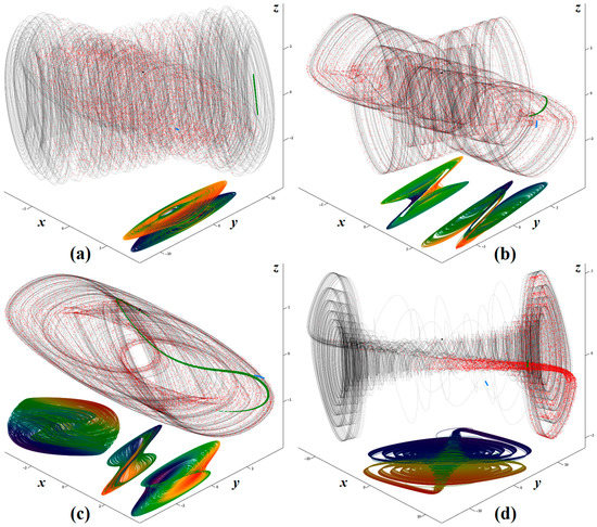
Figure 1.
Selected numerical results associated with analyzed dynamical system (1): (a) z11 = 1.1 Ω, z12 = 1.5 Ω, z22 = 1 Ω, β = 12 Ω, (b) z11 = 1.1 Ω, z12 = 1.3 Ω, z22 = 1 Ω, β = 12 Ω, (c) z11 = 1.2 Ω, z12 = 1.3 Ω, z22 = 1 Ω, β = 4 Ω, and (d) z11 = 1.1 Ω, z12 = 1.4 Ω, z22 = 1 Ω, β = 18 Ω.
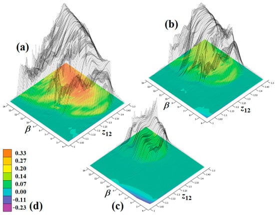
Figure 2.
Rainbow-scaled surface-contour plot of the largest LE as function of principal system parameters: (a) z22 = 1 Ω, (b) z22 = 1.05 Ω, (c) z22 = 1.1 Ω, (d) color legend valid for all plots.
Of course, the input parameters of the numerical routines mentioned above should be chosen according to the advice provided by authors of paper [167]. Since eigenvalues associated with fixed points of system (1) can be easily calculated, a minimal time step to preserve the numerical stability of the FORK method can also be established. The chosen value of 10 ms is sufficiently small, and its further decrease leads to qualitatively the same time domain outputs. In fact, questions about numerical stability and the reliability of the integration process are very topical in the case of chaotic dynamics. The accuracy of the numerical solution of differential equations is always affected by the numerical noise, namely truncation, and round-off errors. However, these errors can be minimized by the strategy known as clean numerical simulation [168]. The author in this paper assumes an integration routine based on the Taylor expansion of nonlinear functions f(x) that describes dynamical flow . Forecasting over the long-time interval becomes possible even for chaotic dynamics under two conditions, 1. if the order of the Taylor expansion is significantly high, i.e., the higher order derivatives of f(x) are considered, and 2. numerical results can be expressed by a large enough number of digits. Evidently, the above-mentioned requirements cannot be satisfied completely, but only to some extent. Interesting notes about known integration schemes used to obtain an approximate solution to the chaotic dynamical system (the famous Lorenz equations) are provided in paper [169]. The author suggests several ways to improve the reliability of numerical analysis, specifically the numerical integration process that utilizes the Taylor series expansion. For the quadratic polynomial vector field, the author derives explicit formulas for power series coefficients and estimates the radius of convergence. The proposed approach can be used in the case of the cubic polynomial nonlinearity of system (1). An example of the circuitry realization of the Lorenz system is provided as well, although unfortunately without experimental verification. Paper [170] can be understood as a direct extension of the above-mentioned ideas. An approach known as the firmly grounded backward-forward integration method has been algorithmized, and was applied to the construction of a high-precision approximate solution of the chaotic dynamics, namely piecewise smooth chaotic systems having quadratic nonlinearity or systems with hysteresis. It is shown and discussed that, for the conventional numerical integration methods such as FORK, chaotic systems exhibit sensitivity to time step-size.
One possible circuitry realization of dynamical system (1) is depicted in Figure 3a. This network is described by the following set of ordinary differential equations
where K = 0.1 is the internally trimmed transfer constant of the second analog multiplier in a cascade. To avoid the necessity of using a resistor having a very small value constant, K of the first multiplier in a cascade is compensated with a voltage divider composed of resistors R13 and R14. By comparing coefficients in a dynamical system (1) and (2) and by considering the nominal values of the impedance parameters (z12, z22, β), we can calculate the numerical values of the passive circuit components
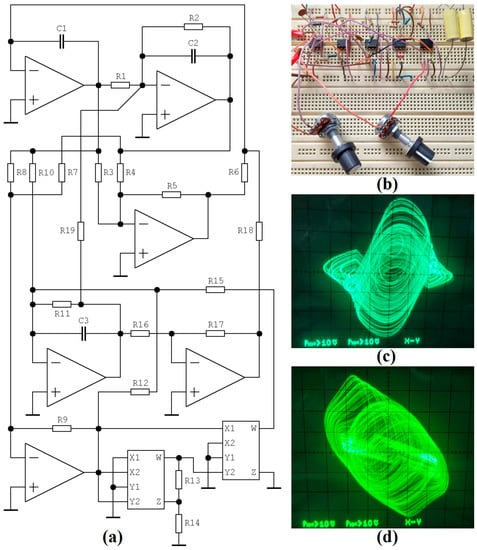
Figure 3.
Pieces of experimental verification: (a) circuitry implementation of chaotic oscillator, design based on the analog computer concept, (b) breadboard realization with two adjustable parameters (R2, R15) via potentiometers, (c) strange attractor visualized in plane projection v3–v1, (d) plane projection v3–v2.
Time constant was chosen as τ = R⋅C = 104⋅10−8 = 100 μs. The oscillator utilizes six conventional operational amplifiers LM833 (two in a single package, dedicated primarily to the audio applications), and two four-quadrant analog multipliers AD633 with a versatile voltage transfer function VW = K⋅(VX1 − VX2)⋅(VY1 − VY2) + VZ. Some experimental results are provided in Figure 3c,d. Dynamical systems (1) and (2) are mutually related via a linear transformation of coordinates.
Numerical analysis should continue by showing additional important plots, such as bifurcation diagrams (a cascade arrangement of suitably chosen Poincaré sections), basins of attraction (in our case near the neighborhood of origin), system energy distribution over the state space, frequency spectrum and entropy of generated signals, etc. These investigations are not provided in order to keep the extent of this paper “focused and reasonably short”. The only, but very important, conclusion coming from the presented results is a good match confirmation between the numerical integration process and real laboratory measurement.
We can mention some facts concerning the “discovery” of a set of the differential Equation (1). The robust chaotic solution has been continuously (during the recent three decades) revealed within naturally non-chaotic, even theoretically linear, mathematical models, both autonomous and driven. From the viewpoint of lumped electronic circuits, chaos and/or hyperchaos can be induced by simply assuming a large signal, that is nonlinear, in a model of at least one active element. In addition, lower-order electronic systems can be subjects of the higher order complicated dynamics if, especially in the high frequency bands, parasitic properties of the circuit components are considered.
Although there is no analytic solution to chaotic dynamics in closed form, this kind of motion can be still distinguished from the complex periodic solution or long chaotic transients. If a calculated, simulated, or measured data sequence is available, the Poincaré sections or Lorenz maps [171] can be utilized to recognize a rising degree of unpredictability of the dynamical flow. For mathematical models that are known exactly, a spectrum of LE can be calculated for both isolated and non-autonomous systems [172,173].
5. Recent Developments and Future Topics
At the present time, research focused on nonlinear dynamics and chaos theory still attracts the attention of a wide range of scientists and design engineers. Research continues, especially toward new mathematical models of a chaotic system with special properties. For example, specific shapes of equilibria are still up-to-date dynamics that exhibit multistability, antimonotonicity, etc. Mathematical models should be also predefined to have specially formed areas with constant divergences of the vector field according to geometrical objects, a cyclically symmetrical vector field, or a vector field consisting of several repeated regions. Recently, Professor Sprott, one of the most respected experts in this field, asked the provocative question, whether we still need to search for new chaotic dynamical systems [174]. His question was subsequently answered by himself, by introducing a very interesting new chaotic third-order system, characterized by time-reversible dynamics and a capacity dimension of equal three.
After many years of intensive research, chaos turns out to be more common than was initially supposed by scientists. The initial “gold fever”, dedicated to finding completely new chaotic systems, gradually turned into a desire to localize the so-called hidden chaotic attractors [175,176]. These are quite hard to find, because they are not excited by the equilibrium point. Therefore, we do not know the initial conditions of the state trajectory that eventually end in the hidden strange attractor. Although it may look as if the hidden chaotic attractors are rare, maybe these are quite common, but very few researchers are interested in the process of their localization.
From the perspective of chaotic oscillators, new and attractive circuit elements are used for circuit design. For example, generative two two-terminal FDNRs are utilized in the typical structure of the single-transistor oscillator to obtain a generator of hyperchaotic self-oscillations. Details can be found in paper [177]. Internal dynamics and/or intrinsic nonlinearity of mem-elements are often used to produce chaotic waveforms, as demonstrated by the authors in paper [178]. Particular attention of researchers is paid to FO mem-elements and their extended benefits in the synthesis of chaotic oscillators. For example, see the mem-capacitor-based chaotic circuit described in paper [179]. These kinds of circuits, i.e., those containing FO mem-elements, are preferably tested via FPGA development kits, as demonstrated in papers [180,181].
The practical design of analog chaotic systems remains a challenge, due to the modern requirements of real applications. For a high-frequency generator of chaotic waveforms, full discrete realization using commercially available active devices is probably not good idea. Although integration technologies also have limitations, the long-term design trend is the implementation of the chaotic system (or its major parts) on-chip. The main advantage is la ow power bias, but at the expense of presenting variations to process technology. Some very interesting studies focused on this topic are provided in papers [126,139], where the authors construct chaotic oscillators robust enough to process-voltage-temperature variations. Another example of a modern CMOS implementation of the chaotic system in described in work [182]. There, 0.18 μm CMOS technology was utilized, and the final circuit exhibits low power consumption of approximately 16 nW and broad-band frequency operation. Development of new active elements that exhibit versatile transfer functions specially designed for the synthesis of chaotic oscillators and with a good frequency response also makes good sense. One such building block, based on I3T25 0.35 μm technology and fabricated in some examples, is proposed in paper [183], where its application in the circuit design of chaotic and hyperchaotic systems is demonstrated via real experiments.
Some authors have become interested in numerical procedures leading to the optimization of chaos via maximization of the largest LE. To do this, evolutionary algorithms can be used, as shown in two new papers [184,185]. Within the frame work of the first paper mentioned, the authors utilize three metaheuristic algorithms: differential evolution, particle swarm optimization, and invasive weed optimization. One hundred individuals run over five hundred generations; a massive increase of the largest LE has been demonstrated.
6. Discussion
Chaos belongs to the natural behavior of many analog circuits, and can be observed within the dynamics of conventional signal-processing building blocks more often than was initially expected. At the same time, electronic circuits are suitable tools for modeling nonlinear dynamics, and can be superior to pure mathematical analysis in two aspects: 1. A chaotic oscillator can be designed providing one-to-one correspondence between its circuit parameter (usually a variable resistor) and a bifurcation parameter of the mathematical model. Continuous and smooth change of circuit quantity in an almost arbitrary range can uncover state attractors that remain unnoticed during numerical analysis. 2. Time constants associated with the constructed circuit can be chosen such that the geometrical structural stability of the observed attractors (especially strange and dense cases) can be assessed visually. This can prevent us from misinterpreting robust chaos as a long transient or numerical artifact. In addition, visual evidence of desired state attractors validates the parameters of numerical analysis applied previously, in the original mathematical model.
This work is not unique and alone in the sense of trying to provide a comprehensive summary of the specific aspects of chaos. Several other papers have already been published, usually supported by a huge number of relevant works cited therein. For example, some elements for a history of dynamical systems theory are provided in a paper having the same title [186]. Pioneering work [187] gives a nice explanation of nonlinear dynamics observed within higher-order oscillatory circuits, both autonomous and driven. Detailed mathematical analysis have been provided by the author, in times when the term chaos has not yet been associated with the unpredictable motion of nonlinear electronic systems. Among the very interesting books (selections of papers) covering wide areas of the design and applications of chaotic oscillators are [188,189,190,191]. Some new directions of future research in the area of chaotic systems are suggested in [192].
Despite the large number of articles cited in this work, this summary cannot be considered as complete, or as explaining every aspect of chaos occurrence in lumped electronic circuits. Of course, the selection of papers cited in this review reflects both the specialization and personal interests of the author. Chaos in electrical engineering still represents an up-to-date topic full of unsolved problems, unanswered questions, and unknown technical applications. Scientists, researchers, and engineers from all over the world are working on them, and the many interesting publications, realizations, theoretical foundations, and other types of outputs increase every day. This fact justifies the existence of journals oriented toward chaos, and Special Issues, such as Mathematical modeling, analysis, and applications of complex dynamics in electrical engineering, were opened in the journal Mathematics, with the kind support of the editorial staff.
Excited and full of expectations, I am looking forward to new future theoretical as well as practical discoveries in the research field of nonlinear dynamics and chaos theory.
Funding
This research was funded by BRNO UNIVERSITY OF TECHNOLOGY, project number FEKT-S-20-6361.
Data Availability Statement
Not applicable.
Conflicts of Interest
The author declares no conflict of interest.
References
- Hasler, M.J. Electrical circuits with chaotic behavior. Proc. IEEE 1987, 75, 1009–1021. [Google Scholar] [CrossRef]
- Matsumoto, T. Chaos in electronic circuits. Proc. IEEE 1987, 75, 1033–1057. [Google Scholar] [CrossRef]
- Matsumoto, T. A chaotic attractor from Chua’s circuit. IEEE Trans. Circuits Syst. 1984, 31, 1055–1058. [Google Scholar] [CrossRef]
- Kennedy, M.P. Robust op amp realization of Chua’s circuit. Frequenz 1992, 46, 66–80. [Google Scholar] [CrossRef]
- Chua, L.O.; Lin, G.N. Canonical realization of Chua’s circuit family. IEEE Trans. Circuits Syst. 1990, 37, 885–902. [Google Scholar] [CrossRef]
- Elwakil, A.S.; Kennedy, M.P. Improved implementation of Chua’s oscillator using current feedback op amp. IEEE Trans. Circuits Syst. 2000, 47, 76–79. [Google Scholar] [CrossRef]
- Zhong, G.Q. Implementation of Chua’s circuit with a cubic nonlinearity. IEEE Trans. Circuits Syst. I Fundam. Theory Appl. 1994, 41, 934–941. [Google Scholar] [CrossRef]
- Spany, V.; Galajda, P.; Guzan, M.; Pivka, L.; Olejar, M. Chua’s singularities: Great miracle in circuit theory. Int. J. Bifurc. Chaos 2010, 20, 2993–3006. [Google Scholar] [CrossRef]
- Guzan, M. Variations of boundary surface in Chua’s circuit. Radioengineering 2015, 24, 814–823. [Google Scholar] [CrossRef]
- Ogorzalek, M.J. Order and chaos in a third-order RC ladder network with nonlinear feedback. IEEE Trans. Circuits Syst. 1989, 36, 1221–1232. [Google Scholar] [CrossRef]
- Itoh, M. Synthesis of electronic circuits for simulating nonlinear dynamics. Int. J. Bifurc. Chaos 2001, 11, 605–653. [Google Scholar] [CrossRef]
- Scanlan, S.O. Synthesis of piecewise-linear chaotic oscillators with prescribed eigenvalues. IEEE Trans. Circuits Syst. I Fundam. Theory Appl. 1999, 46, 1057–1064. [Google Scholar] [CrossRef]
- Gotz, M.; Feldmann, U.; Schwarz, W. Synthesis of higher dimensional Chua circuits. IEEE Trans. Circuits Syst. I Fundam. Theory Appl. 1993, 40, 854–860. [Google Scholar] [CrossRef]
- Petrzela, J.; Polak, L. Minimal realizations of autonomous chaotic oscillators based on trans-immittance filters. IEEE Access 2019, 7, 17561–17577. [Google Scholar] [CrossRef]
- Elwakil, A.S.; Kennedy, M.P. Chaotic oscillator configuration using a frequency dependent negative resistor. Int. J. Circuit Theory Appl. 2000, 28, 69–73. [Google Scholar] [CrossRef]
- Srisuchinwong, B.; Treetanakorn, R. Current-tunable chaotic jerk circuit based on only unity-gain amplifier. Electron. Lett. 2014, 50, 1815–1817. [Google Scholar] [CrossRef]
- Elwakil, A.S.; Kennedy, M.P. Novel chaotic oscillator configuration using a diode-inductor composite. Int. J. Electron. 2000, 87, 397–406. [Google Scholar] [CrossRef]
- Elwakil, A.S.; Kennedy, M.P. A semi-systematic procedure for producing chaos from sinusoidal oscillators using diode-inductor and FET-capacitor composites. IEEE Trans. Circuits Syst. I Fundam. Theory Appl. 2000, 47, 582–590. [Google Scholar] [CrossRef]
- Kennedy, M.P. Chaos in the Colpitts oscillator. IEEE Trans. Circuits Syst. I Fundam. Theory Appl. 1994, 41, 771–774. [Google Scholar] [CrossRef]
- Wafo Tekam, R.B.; Kengne, J.; Kenmoe, G.D. High frequency Colpitts oscillator: A simple configuration for chaos generation. Chaos Solitons Fractals 2019, 126, 351–360. [Google Scholar] [CrossRef]
- Kengne, J.; Chedjou, J.C.; Fono, V.A.; Kyamakya, K. On the analysis of bipolar transistor based chaotic circuits: Case of a two-stage Colpitts oscillator. Nonlinear Dyn. 2012, 67, 1247–1260. [Google Scholar] [CrossRef]
- Kvarda, P. Chaos in Hartley’s oscillator. Int. J. Bifurc. Chaos 2011, 12, 2229–2232. [Google Scholar]
- Tchitnga, R.; Fotsin, H.S.; Nana, B.; Fotso, P.H.L.; Woafo, P. Hartley’s oscillator: The simplest chaotic two-component circuit. Chaos Solitons Fractals 2012, 45, 306–313. [Google Scholar] [CrossRef]
- Petrzela, J. Chaotic and hyperchaotic dynamics of a Clapp oscillator. Mathematics 2022, 10, 1868. [Google Scholar] [CrossRef]
- Elwakil, A.S.; Kennedy, M.P. A family of Wien-type oscillators modified for chaos. Int. J. Circuit Theory Appl. 1997, 25, 561–579. [Google Scholar] [CrossRef]
- Kilic, R.; Yildrim, F. A survey of Wien bridge-based chaotic oscillators: Design and experimental issues. Chaos Solitons Fractals 2008, 38, 1394–1410. [Google Scholar] [CrossRef]
- Tamasevicius, A.; Mykolaitis, G.; Cenys, A. Wien-bridge chaotic circuit with comparator. Electron. Lett. 1998, 34, 606–608. [Google Scholar] [CrossRef]
- Kushwaha, A.K.; Paul, S.K. Inductorless realization of Chua’s oscillator using DVCCTA. Analog. Integr. Circuits Signal Process. 2016, 88, 137–150. [Google Scholar] [CrossRef]
- Hosokawa, Y.; Nishio, Y.; Ushida, A. Analysis of chaotic phenomena in two RC phase shift oscillators coupled by a diode. IEICE Trans. Fundam. 2001, E84-A, 2288–2295. [Google Scholar]
- Tamasevicius, A.; Mykolaitis, G.; Pyragas, V.; Pyragas, K. A simple chaotic oscillator for educational purposes. Eur. J. Phys. 2004, 26, 61. [Google Scholar]
- Sam-Um, W.; Suksiri, B.; Ketthong, P. A simple RLCC-Diode-Opamp chaotic oscillator. Int. J. Bifurc. Chaos 2014, 24, 1450155. [Google Scholar] [CrossRef]
- Petrzela, J. Chaotic behavior of state variable filters with saturation-type integrators. Electron. Lett. 2015, 51, 1159–1161. [Google Scholar] [CrossRef]
- Petrzela, J. On the existence of chaos in the electronically adjustable structures of the state variable filters. Int. J. Circuit Theory Appl. 2016, 44, 1779–1797. [Google Scholar] [CrossRef]
- Endo, T.; Chua, L.O. Chaos from phase-locked loops. IEEE Trans. Circuits Syst. 1988, 35, 987–1003. [Google Scholar] [CrossRef]
- Harb, B.A.; Harb, A.M. Chaos and bifurcation in a third-order phase locked loops. Chaos Solitons Fractals 2004, 19, 667–672. [Google Scholar] [CrossRef]
- Piqueira, J.R.C. Hopf bifurcation and chaos in a third-order phase-locked loop. Commun. Nonlinear Sci. Numer. Simul. 2017, 42, 178–186. [Google Scholar] [CrossRef]
- Endo, T. A review of chaos and nonlinear dynamics in phase-locked loops. J. Frankl. Inst. 1994, 331, 859–902. [Google Scholar] [CrossRef]
- Petrzela, J. Multi-valued static memory with resonant tunneling diodes as natural source of chaos. Nonlinear Dyn. 2018, 94, 1867–1887. [Google Scholar] [CrossRef]
- Petrzela, J. Strange attractors generated by multiple-valued static memory cell with polynomial approximation of resonant tunneling diodes. Entropy 2018, 20, 697. [Google Scholar] [CrossRef]
- Galajda, P.; Guzan, M.; Spany, V. The state space mystery with negative load in multiple-valued logic. Radioengineering 2008, 17, 19–24. [Google Scholar]
- Petrzela, J. Generalized single stage class C amplifier: Analysis from the viewpoint of chaotic behavior. Appl. Sci. 2020, 10, 5025. [Google Scholar] [CrossRef]
- Petrzela, J. Evidence of strange attractors in class C amplifier with single bipolar transistor: Polynomial and piecewise-linear case. Entropy 2021, 23, 175. [Google Scholar] [CrossRef] [PubMed]
- Petrzela, J. New chaotic oscillator derived from class C single transistor-based amplifier. Math. Probl. Eng. 2020, 2020, 1–18. [Google Scholar] [CrossRef]
- Petrzela, J.; Rujzl, M. Chaotic oscillations in cascoded and Darlington-type amplifier having generalized transistors. Mathematics 2022, 10, 532. [Google Scholar] [CrossRef]
- Hamill, D.C.; Jeffries, D.J. Subharmonics and chaos in a controlled switched-mode power converter. IEEE Trans. Circuits Syst. 1988, 35, 1059–1061. [Google Scholar] [CrossRef]
- Deane, J.H.B.; Hamill, D.C. Chaotic behaviour in current-mode controlled DC-DC converter. Electron. Lett. 1991, 27, 1172–1173. [Google Scholar] [CrossRef]
- Di Bernardo, M.; Garofalo, F.; Glielmo, L.; Vasca, F. Switchings, bifurcations, and chaos in DC/DC converters. IEEE Trans. Circuits Syst. I Fundam. Theory Appl. 1998, 45, 133–141. [Google Scholar] [CrossRef]
- Tse, C.K. Flip bifurcation and chaos in three-state boost switching regulators. IEEE Trans. Circuits Syst. I Fundam. Theory Appl. 1994, 41, 16–23. [Google Scholar] [CrossRef]
- Zhusubaliyev, Z.T.; Mosekilde, E. Bifurcations and Chaos in Piecewise-Smooth Dynamical Systems; World Scientific: Singapore, 2003; 376p. [Google Scholar]
- Di Bernardo, M.; Budd, C.J.; Champneys, A.R.; Kowalczyk, P. Piecewise-Smooth Dynamical Systems; Springer: New York, NY, USA, 2008; 481p. [Google Scholar]
- Banerjee, S.; Verghese, G.C. Nonlinear Phenomena in Power Electronics: Bifurcations, Chaos, Control, and Applications; Wiley: Hoboken, NJ, USA, 2001; 480p. [Google Scholar]
- Niu, Q. Study of bifurcation and chaos in boost converter based on energy balance model. Energy Power Eng. 2009, 1, 38–43. [Google Scholar] [CrossRef]
- Tse, C.K.; Chan, W.C.Y. Chaos from a current-programmed cuk converter. Int. J. Circuit Theory Appl. 1995, 23, 217–225. [Google Scholar] [CrossRef]
- Wong, S.C.; Tse, C.K.; Tam, K.C. Intermittent chaotic operation in switching power converters. Int. J. Bifurc. Chaos 2011, 14, 2971–2978. [Google Scholar] [CrossRef]
- Zhou, X.; Li, J.; Youjie, M. Chaos phenomena in dc-dc converter and chaos control. Proceedia Eng. 2012, 29, 470–473. [Google Scholar] [CrossRef]
- Fossas, E.; Olivar, G. Study of chaos in the buck converter. IEEE Trans. Circuits Syst. I Fundam. Theory Appl. 1996, 43, 13–25. [Google Scholar] [CrossRef]
- Natsheh, A.; Kettleborough, J.; Janson, N. Experimental study of controlling chaos in a DC-DC boost converter. Chaos Solitons Fractals 2009, 40, 2500–2508. [Google Scholar] [CrossRef]
- El Aroudi, A.; Debbat, M.; Giral, R.; Olivar, G.; Benadero, L.; Toribo, E. Bifurcations in DC-DC switching converters: Review of methods and applications. Int. J. Bifurc. Chaos 2005, 15, 1549–1578. [Google Scholar] [CrossRef]
- Rodriguez-Vazquez, A.; Huertas, J.; Chua, L.O. Chaos in switched-capacitor circuit. IEEE Trans. Circuits Syst. 1985, 32, 1083–1085. [Google Scholar] [CrossRef]
- Nagy, I. Nonlinear phenomena in power electronics. Automatika 2001, 42, 117–132. [Google Scholar]
- Galajda, P.; Kocur, D. Chua’s circuit in spread spectrum communication systems. Radioengineering 2002, 11, 6–10. [Google Scholar]
- Itoh, M. Spread spectrum communication via chaos. Int. J. Bifurc. Chaos 1999, 9, 155–213. [Google Scholar] [CrossRef]
- Corron, N.J.; Hahs, D.W. A new approach to communications using chaotic signals. IEEE Trans. Circuits Syst. I Fundam. Theory Appl. 1997, 44, 373–382. [Google Scholar] [CrossRef]
- Trejo-Guerra, R.; Tlelo-Cuautle, E.; Cruz-Hernandez, C.; Sanchez-Lopez, C. Chaotic communication system using Chua’s oscillators realized with CCII+s. Int. J. Bifurc. Chaos 2009, 19, 4217–4226. [Google Scholar] [CrossRef]
- Chien, T.-I.; Liao, T.-L. Design of secure digital communication systems using chaotic modulation, cryptography and chaotic synchronization. Chaos Solitons Fractals 2005, 24, 241–255. [Google Scholar] [CrossRef]
- Kaddoum, G. Wireless chaos-based communication systems: A comprehensive survey. IEEE Access 2016, 4, 2621–2648. [Google Scholar] [CrossRef]
- Yang, T. A survey of chaotic secure communication systems. Int. J. Comput. Cogn. 2004, 2, 81–130. [Google Scholar]
- Stojanovski, T.; Kocarev, L. Chaos-based random number generators. Part I: Analysis. IEEE Trans. Circuits Syst. I Fundam. Theory Appl. 2001, 48, 281–288. [Google Scholar] [CrossRef]
- Stojanovski, T.; Pihl, J.; Kocarev, L. Chaos-based random number generators. Part II: Practical realization. IEEE Trans. Circuits Syst. I Fundam. Theory Appl. 2001, 48, 382–385. [Google Scholar] [CrossRef]
- Drutarovsky, M.; Galajda, P. A robust chaos-based true random number generator embedded in reconfigurable switched-capacitor hardware. Radioengineering 2007, 16, 120–127. [Google Scholar]
- Sprott, J.C.; Thio, W.J. A chaotic circuit for producing gaussian random numbers. Int. J. Bifurc. Chaos 2020, 30, 2050116. [Google Scholar] [CrossRef]
- Li, H.; Zhang, B.; Li, Z.; Halang, W.A.; Chen, G. Controlling DC-DC converters by chaos-based pulse width modulation to reduce EMI. Chaos Solitons Fractals 2009, 42, 1378–1387. [Google Scholar] [CrossRef]
- Elwakil, A.S.; Soliman, A.M. Current conveyor chaos generators. IEEE Trans. Circuits Syst. I Fundam. Theory Appl. 1999, 46, 393–398. [Google Scholar] [CrossRef]
- Bernat, P.; Balaz, I. RC autonomous circuits with chaotic behavior. Radioengineering 2002, 11, 1–5. [Google Scholar]
- Tokunaga, R.; Komuro, M.; Matsumoto, T.; Chua, L.O. Lorenz attractor from an electrical circuit with uncoupled continuous piecewise-linear resistor. Int. J. Circuit Theory Appl. 1989, 17, 71–85. [Google Scholar] [CrossRef]
- Kumari, B.; Gupta, N. Realization of chaotic circuits using lambda diode. J. Circuits Syst. Comput. 2017, 26, 1750189. [Google Scholar] [CrossRef]
- Minati, L.; Frasca, M.; Oswiecimka, P.; Faes, L.; Drozd, S. Atypical transistor-based chaotic oscillators: Design, realization, and diversity. Chaos 2017, 27, 073113. [Google Scholar] [CrossRef]
- Petrzela, J.; Pospisil, V. Nonlinear resistor with polynomial AV characteristics and its application in chaotic oscillator. Radioengineering 2004, 13, 20–25. [Google Scholar]
- Petrzela, J.; Kolka, Z.; Hanus, S. Simple chaotic oscillator: From mathematical model to practical experiment. Radioengineering 2006, 15, 6–12. [Google Scholar]
- Petrzela, J.; Slezak, J. Conservative chaos generators with CCII+ based on mathematical model of nonlinear oscillator. Radioengineering 2008, 17, 19–24. [Google Scholar]
- Kataoka, M.; Saito, T. A two-port VCCS chaotic oscillator and quad screw attractor. IEEE Trans. Circuits Syst. I Fundam. Theory Appl. 2001, 48, 1057–1064. [Google Scholar] [CrossRef]
- Petrzela, J.; Sotner, R. Binary memory implemented by using variable gain amplifiers with multipliers. IEEE Access 2020, 8, 197276–197286. [Google Scholar] [CrossRef]
- Biolek, D.; Senani, R.; Biolkova, V.; Kolka, Z. Active elements for analog signal processing: Classification, review, and new proposals. Radioengineering 2008, 17, 15–32. [Google Scholar]
- Kiers, K.; Klein, T.; Kolb, J.; Price, S.; Sprott, J.C. Chaos in a nonlinear analog computer. Int. J. Bifurc. Chaos 2004, 14, 2867–2873. [Google Scholar] [CrossRef]
- Piper, J.R.; Sprott, J.C. Simple autonomous chaotic circuits. IEEE Trans. Circuits Syst. II Express Briefs 2010, 57, 730–734. [Google Scholar] [CrossRef]
- Sprott, J.C. A new chaotic jerk circuit. IEEE Trans. Circuits Syst. II Express Briefs 2011, 58, 240–243. [Google Scholar] [CrossRef]
- Petrzela, J.; Hrubos, Z.; Gotthans, T. Modeling deterministic chaos using electronic circuits. Radioengineering 2011, 20, 438–444. [Google Scholar]
- Klomkarn, K.; Sooraksa, P.; Chen, G. New construction of mixed-mode chaotic circuits. Int. J. Bifurc. Chaos 2010, 20, 1485–1497. [Google Scholar] [CrossRef]
- Petrzela, J.; Gotthans, T.; Guzan, M. Current-mode network structures dedicated for simulation of dynamical systems with plane continuum of equilibrium. J. Circuits Syst. Comput. 2018, 27, 1830004. [Google Scholar] [CrossRef]
- Almatroud, O.A.; Tamba, V.K.; Grassi, G.; Pham, V.-T. An oscillator without linear terms: Infinite equilibria, chaos, realization, and application. Mathematics 2021, 9, 3315. [Google Scholar] [CrossRef]
- Sprott, J.C. A proposed standard for the publication of new chaotic systems. Int. J. Bifurc. Chaos 2011, 21, 2391–2394. [Google Scholar] [CrossRef]
- Gotthans, T.; Sprott, J.C.; Petrzela, J. Simple chaotic flow with circle and square equilibrium. Int. J. Bifurc. Chaos 2016, 26, 1650137. [Google Scholar] [CrossRef]
- Pham, V.-T.; Jafari, S.; Volos, C.; Giakoumis, A.; Vaidyanathan, S.; Kapitaniak, T. A chaotic system with equilibria located on the rounded square loop and its circuit implementation. IEEE Trans. Circuits Syst. II Express Briefs 2016, 63, 878–882. [Google Scholar] [CrossRef]
- Karthikeyan, R.; Akgul, A.; Jafari, S.; Karthikeyan, A.; Koyuncu, I. Chaotic chameleon: Dynamical analysis, circuit implementation, FPGA design and fractional-order form with basic analysis. Chaos Solitons Fractals 2017, 103, 476–487. [Google Scholar]
- Kapitaniak, T.; Mohammadi, S.A.; Mekhilef, S.; Alsaadi, F.E.; Hayat, T.; Pham, V.-T. A new chaotic system with stable equilibrium: Entropy analysis, parameter estimation, and circuit design. Entropy 2018, 20, 670. [Google Scholar] [CrossRef] [PubMed]
- Pham, V.-T.; Ali, D.S.; Al-Saidi, N.M.G.; Rajagopal, K.; Alsaadi, F.E.; Jafari, S. A novel mega-stable chaotic circuit. Radioengineering 2020, 29, 140–146. [Google Scholar] [CrossRef]
- Lai, Q.; Akgul, A.; Li, C.H.; Xu, G.; Cavusoglu, U. A new chaotic system with multiple attractors: Dynamic analysis, circuit realization and S-box design. Entropy 2018, 20, 12. [Google Scholar] [CrossRef] [PubMed]
- Jafari, S.; Sprott, J.C.; Pham, V.-T.; Volos, C.; Li, C. Simple chaotic 3D flows with surfaces of equilibria. Nonlinear Dyn. 2016, 86, 1349–1358. [Google Scholar] [CrossRef]
- Li, C.; Peng, Y.; Tao, Z.; Sprott, J.C.; Jafari, S. Coexisting infinite equilibria and chaos. Int. J. Bifurc. Chaos 2021, 31, 2130014. [Google Scholar] [CrossRef]
- Munoz-Pacheco, J.M.; Tlelo-Cuautle, E.; Toxqui-Toxqui, I.; Sanchez-Lopez, C.; Trejo-Guerra, R. Frequency limitations in generating multi-scroll chaotic attractors using CFOAs. Int. J. Electron. 2014, 101, 1559–1569. [Google Scholar] [CrossRef]
- Ma, J.; Wang, L.; Duan, S.; Xu, Y. A multi-wing butterfly chaotic system and its implementation. Int. J. Circuit Theory Appl. 2017, 45, 1873–1884. [Google Scholar] [CrossRef]
- Karimov, T.; Nepomuceno, E.G.; Druzhina, O.; Karimov, A.; Butusov, D. Chaotic oscillators as inductive sensors: Theory and practice. Sensors 2019, 19, 4314. [Google Scholar] [CrossRef]
- Sprott, J.C. Simple chaotic systems and circuits. Am. J. Phys. 2000, 68, 758–763. [Google Scholar] [CrossRef]
- Sprott, J.C. A new class of chaotic circuit. Phys. Lett. A 2000, 266, 19–23. [Google Scholar] [CrossRef]
- Gotthans, T.; Petrzela, J. Experimental study of sampled labyrinth chaos. Radioengineering 2011, 20, 873–879. [Google Scholar]
- Singh, J.P.; Roy, B.K. Simplest hyperchaotic system with only one piecewise linear term. Electron. Lett. 2019, 55, 378–380. [Google Scholar] [CrossRef]
- Yang, X.S.; Li, Q.; Chen, G. A twin-star hyperchaotic attractor and its circuit implementation. Int. J. Circuit Theory Appl. 2003, 31, 637–640. [Google Scholar] [CrossRef]
- Tamasevicius, A.; Namajunas, A.; Cenys, A. Simple 4D chaotic oscillator. Electron. Lett. 1996, 32, 957–958. [Google Scholar] [CrossRef]
- Varrientos, J.E.; Sanchez-Sinencio, E. A 4-D chaotic oscillator based on a differential hysteresis comparator. IEEE Trans. Circuits Syst. I Fundam. Theory Appl. 1998, 45, 3–10. [Google Scholar] [CrossRef]
- Li, C.; Sprott, J.C.; Thio, W.; Zhu, H. A new piecewise linear hyperchaotic circuit. IEEE Trans. Circuits Syst. II Express Briefs 2014, 61, 977–981. [Google Scholar] [CrossRef]
- Folifack Signing, V.R.; Kengne, J.; Mboupda Pone, J.R. Antimonotonicity, chaos, quasi-periodicity and coexistence of hidden attractors in a new simple 4-D chaotic system with hyperbolic cosine nonlinearity. Chaos Solitons Fractals 2019, 118, 187–198. [Google Scholar] [CrossRef]
- Yujun, N.; Xingyuan, W.; Mingjun, W.; Huanguang, Z. A new hyperchaotic system and its circuitry implementation. Commun. Nonlinear Sci. Numer. Simul. 2010, 15, 3518–3524. [Google Scholar] [CrossRef]
- Cernys, A.; Tamasevicius, A.; Baziliauskas, A.; Krivickas, R.; Lindberg, E. Hyperchaos in coupled Colpitts oscillators. Chaos Solitons Fractals 2003, 17, 349–353. [Google Scholar] [CrossRef]
- Tamba, V.K.; Fotsin, H.B.; Kengne, J.; Kapche Tagne, F.; Talla, P.K. Coupled inductor-based chaotic Colpitts oscillators: Mathematical modeling and synchronization issues. Eur. Phys. J. Plus 2015, 130, 137. [Google Scholar] [CrossRef]
- Petrzela, J. Chaotic and hyperchaotic self-oscillations of lambda diode composed by generalized bipolar transistors. Appl. Sci. 2021, 11, 3326. [Google Scholar] [CrossRef]
- Petrzela, J. Hyperchaotic self-oscillations of two-stage class C amplifier with generalized transistors. IEEE Access 2021, 9, 62182–62194. [Google Scholar] [CrossRef]
- Caponeto, R.; Di Mauro, A.; Fortuna, L.; Frasca, M. Field programmable analog array to implement a programmable Chua’s circuit. Int. J. Bifurc. Chaos 2005, 15, 1829–1836. [Google Scholar] [CrossRef]
- Li, C.; Thio, W.J.; Sprott, J.C.; Iu, H.H.; Xu, Y. Constructing infinitely many attractors in a programmable chaotic circuit. IEEE Access 2018, 6, 29003–29012. [Google Scholar] [CrossRef]
- Dalkiran, F.Y.; Sprott, J.C. Simple chaotic hyperjerk system. Int. J. Bifurc. Chaos 2016, 26, 1650189. [Google Scholar] [CrossRef]
- Kilic, R. Universal programmable chaos generator: Design and implementation issues. Int. J. Bifurc. Chaos 2010, 20, 419–435. [Google Scholar] [CrossRef]
- Guillén-Fernández, O.; Moreno-López, M.F.; Tlelo-Cuautle, E. Issues on applying one- and multi-step numerical methods to chaotic oscillators for FPGA implementation. Mathematics 2021, 9, 151. [Google Scholar] [CrossRef]
- Pham, V.-T.; Vaidyanathan, S.; Volos, C.; Jafari, S. Hidden attractor in a chaotic system with an exponential nonlinear term. Eur. Phys. J. Spec. Top. 2015, 224, 1507–1517. [Google Scholar] [CrossRef]
- Ozoguz, S.; Sengor, N.S. On the realization of NPN-only log-domain chaotic oscillators. IEEE Trans. Circuits Syst. I Fundam. Theory Appl. 2003, 50, 291–294. [Google Scholar] [CrossRef]
- Yener, S.C.; Kuntman, H.H. Fully CMOS memristor based chaotic circuit. Radioengineering 2014, 23, 1140–1149. [Google Scholar]
- Rodriguez-Vazquez, A.; Delgado-Restituto, M. CMOS design of chaotic oscillators using state variables: A monolithic Chua’s circuit. IEEE Trans. Circuits Syst. II Analog. Digit. Signal Process. 1993, 40, 596–613. [Google Scholar] [CrossRef]
- Carbajal-Gomez, V.H.; Tlelo-Cuautle, E.; Munoz-Pacheco, J.M.; Gerardo de la Fraga, L.; Sanchez-Lopez, F.V. Optimization and CMOS design of chaotic oscillators robust to PVT variations. Integration 2019, 65, 32–42. [Google Scholar] [CrossRef]
- Radwan, A.G.; Soliman, A.M.; El-Sedeek, A.L. Low-voltage MOS chaotic oscillator based on the nonlinearity of gm. J. Circuits Syst. Comput. 2004, 13, 101. [Google Scholar] [CrossRef]
- Hosokawa, Y.; Nishio, Y. Simple chaotic circuit using CMOS ring oscillators. Int. J. Bifurc. Chaos 2004, 14, 2513–2524. [Google Scholar] [CrossRef]
- Delgado-Restituto, M.; Linan, M.; Ceballos, J.; Rodriguez-Vazquez, A. Bifurcations and synchronization using an integrated programmable chaotic circuit. Int. J. Bifurc. Chaos 1997, 7, 1737–1773. [Google Scholar] [CrossRef]
- Trejo-Guerra, R.; Tlelo-Cuautle, E.; Carbajal-Gomez, V.H.; Rodriguez-Gomez, G.A. A survey on the integrated design of chaotic oscillators. Appl. Math. Comput. 2013, 219, 5113–5122. [Google Scholar] [CrossRef]
- Sanchez-Lopez, C.; Trejo-Guerra, R.; Munoz-Pacheco, J.M.; Tlelo-Cuautle, E. N-scroll chaotic attractors from saturated functions employing CCII+s. Nonlinear Dyn. 2010, 61, 331–341. [Google Scholar] [CrossRef]
- Zhang, X.; Wang, C.H. A novel multi-attractor period multi-scroll chaotic integrated circuit based on CMOS wide adjustable CCCII. IEEE Access 2019, 7, 16336–16350. [Google Scholar]
- Tang, W.K.S.; Zhong, G.Q.; Chen, G.; Man, K.F. Generation of N-scroll attractors via sine function. IEEE Trans. Circuits Syst. I Fundam. Theory Appl. 2001, 48, 1369–1372. [Google Scholar] [CrossRef]
- Yalcin, M.E.; Suykens, J.A.K.; Vandewalle, J.; Ozoguz, S. Families of scroll grid attractors. Int. J. Bifurc. Chaos 2002, 12, 23–41. [Google Scholar] [CrossRef]
- Yu, S.; Lu, J.; Leung, H.; Chen, G. Design and implementation of n-scroll chaotic attractors from a general jerk circuit. IEEE Trans. Circuits Syst. I Regul. Pap. 2005, 52, 1459–1476. [Google Scholar]
- Lu, J.; Chen, G. Generating multiscroll chaotic attractors: Theories, methods and applications. Int. J. Bifurc. Chaos 2006, 16, 775–858. [Google Scholar] [CrossRef]
- Trejo-Guerra, R.; Tlelo-Cuautle, E.; Jimenez-Fuentes, J.M.; Sanchez-Lopez, C.; Munoz-Pacheco, J.M.; Espinosa-Flores-Verdad, G.; Rocha-Perez, J.M. Integrated circuit generating 3- and 5-scroll attractors. Commun. Nonlinear Sci. Numer. Simul. 2012, 17, 4328–4335. [Google Scholar] [CrossRef]
- Trejo-Guerra, R.; Tlelo-Cuautle, E.; Jimenez-Fuentes, J.M.; Munoz-Pacheco, J.M.; Sanchez-Lopez, C. Multiscroll floating gate based integrated chaotic oscillator. Int. J. Circuit Theory Appl. 2013, 41, 831–843. [Google Scholar] [CrossRef]
- Carbajal-Gomez, V.H.; Tlelo-Cuautle, E.; Sanchez-Lopez, C.; Fernandez-Fernandez, F.V. PVT-robust CMOS programmable chaotic oscillator: Synchronization of two 7-scroll attractors. Electronics 2018, 7, 252. [Google Scholar] [CrossRef]
- Jin, J. Programmable multi-direction fully integrated chaotic oscillator. Microelectron. J. 2018, 75, 27–34. [Google Scholar] [CrossRef]
- Hulub, M.; Frasca, M.; Fortuna, L.; Arena, P. Implementation and synchronization of 3 × 3 grid scroll chaotic circuits with analog programmable devices. Chaos 2006, 16, 013121. [Google Scholar] [CrossRef]
- Pano-Azucena, A.D.; Rangel-Magdaleno, J.J.; Tlelo-Cuautle, E.; Quintas-Valles, A.J. Arduino-based chaotic secure communication system using multi-directional multiscroll chaotic oscillators. Nonlinear Dyn. 2017, 87, 2203–2217. [Google Scholar] [CrossRef]
- Biolek, D.; Di Ventra, M.; Pershin, Y.V. Reliable SPICE simulations of memristors, memcapacitors and meminductors. Radioengineering 2013, 22, 945–982. [Google Scholar]
- Chua, L.O. Everything you wish to know about memristors but are afraid to ask. Radioengineering 2015, 24, 319–368. [Google Scholar] [CrossRef]
- Biolek, Z.; Biolek, D.; Biolkova, V. Utilization of Euler-Lagrange equations in circuits with memory elements. Radioengineering 2016, 25, 783–789. [Google Scholar] [CrossRef]
- Minati, L.; Gambuzza, L.V.; Thio, W.J.; Sprott, J.C.; Frasca, M. A chaotic circuit based on a physical memristor. Chaos Solitons Fractals 2020, 138, 109990. [Google Scholar] [CrossRef]
- Wang, L.; Drakakis, E.; Duan, S.; He, P.; Liao, X. Memristor model and its application for chaos generation. Int. J. Bifurc. Chaos 2012, 22, 1250205. [Google Scholar] [CrossRef]
- Liu, X.; Wang, J.; Liu, J.; Cao, Y. A new simple chaotic circuit based on memristor and meminductor. Eur. Phys. J. Plus 2021, 136, 1182. [Google Scholar] [CrossRef]
- Muthuswamy, B. Implementing memristor based chaotic circuits. Int. J. Bifurc. Chaos 2010, 20, 1335–1350. [Google Scholar] [CrossRef]
- Kengne, J.; Njitacke, Z.T.; Nguomkam Negou, A.; Fouodji Tsostop, M.; Fotsin, H.B. Coexistence of multiple attractors and crisis route to chaos in a novel chaotic jerk circuit. Int. J. Bifurc. Chaos 2016, 26, 1650081. [Google Scholar] [CrossRef]
- Pham, V.-T.; Buscarino, A.; Fortuna, L.; Frasca, M. Simple memristive time-delay chaotic systems. Int. J. Bifurc. Chaos 2013, 23, 1350073. [Google Scholar] [CrossRef]
- Du, C.; Liu, L.; Zhanh, Z.; Yu, S. A memristive conservative chaotic circuit with two different offset boosting behaviors. AEU-Int. J. Electron. Commun. 2022, 147, 154146. [Google Scholar] [CrossRef]
- Bao, B.; Bao, H.; Wang, N.; Chen, M.; Xu, Q. Hidden extreme multistability in memristive hyperchaotic system. Chaos Solitons Fractals 2017, 94, 102–111. [Google Scholar] [CrossRef]
- Petrzela, J. Fractional-order chaotic memory with wideband constant phase elements. Entropy 2020, 22, 422. [Google Scholar] [CrossRef] [PubMed]
- Zhang, Y.; Lin, P.; Sun, W. Nonlinear control and circuit implementation in coupled nonidentical fractional-order chaotic systems. Fractal Fract. 2022, 6, 428. [Google Scholar] [CrossRef]
- Valencia-Ponce, M.A.; Castañeda-Aviña, P.R.; Tlelo-Cuautle, E.; Carbajal-Gómez, V.H.; González-Díaz, V.R.; Sandoval-Ibarra, Y.; Nuñez-Perez, J.-C. CMOS OTA-based filters for designing fractional-order chaotic oscillators. Fractal Fract. 2021, 5, 122. [Google Scholar] [CrossRef]
- Pham, V.-T.; Kingni, S.T.; Volos, C.H.; Jafari, S.; Kapitaniak, T. A simple three-dimensional fractional-order chaotic system without equilibrium. AEU-Int. J. Electron. Commun. 2017, 78, 220–227. [Google Scholar] [CrossRef]
- Pham, V.-T.; Ouannas, A.; Volos, C.; Kapitaniak, T. A simple fractional-order chaotic system without equilibrium and its synchronization. AEU-Int. J. Electron. Commun. 2018, 86, 69–76. [Google Scholar] [CrossRef]
- Chen, L.; Pan, W.; Wu, R.; Wang, K.; He, Y. Generation and circuit implementation of fractional-order multi-scroll attractors. Chaos Solitons Fractals 2016, 85, 22–31. [Google Scholar] [CrossRef]
- Chen, L.; Pan, W.; Wu, R.; Tenreiro-Machado, J.A.; Lopes, A.M. Design and implementation of grid multi-scroll fractional-order chaotic oscillators. AIP Chaos Interdiscip. J. Nonlinear Sci. 2016, 26, 084303. [Google Scholar] [CrossRef]
- Silva-Juarez, A.; Tlelo-Cuautle, E.; de la Fraga, L.G.; Li, R. FPAA-based implementation of fractional-order chaotic oscillators using first-order active filter blocks. J. Adv. Res. 2020, 25, 77–85. [Google Scholar] [CrossRef] [PubMed]
- Altun, K. FPAA implementations of fractional-order chaotic systems. J. Circuits Syst. Comput. 2021, 30, 2150271. [Google Scholar] [CrossRef]
- Dong, E.; Yuan, M.; Han, F.; Tong, J.; Du, S. Topological horseshoe analysis and FPGA implementation of a classical fractional order chaotic system. IEEE Access 2019, 7, 129095–129103. [Google Scholar] [CrossRef]
- Shah, D.K.; Charasiya, R.B.; Vyawahare, V.A.; Pichhode, K.; Patil, M.D. FPGA implementation of fractional-order chaotic systems. AEU-Int. J. Electron. Commun. 2017, 78, 245–257. [Google Scholar] [CrossRef]
- Petrzela, J. Optimal piecewise-linear approximation of the quadratic chaotic dynamics. Radioengineering 2012, 21, 20–28. [Google Scholar]
- Jafari, S.; Sprott, J.C.; Pham, V.-T.; Golpayegani, S.M.R.H. A new cost function for parameter estimation of chaotic systems using return maps as fingerprints. Int. J. Bifurc. Chaos 2014, 24, 1567–1580. [Google Scholar] [CrossRef]
- Valencia-Ponce, M.A.; Tlelo-Cuautle, E.; de la Fraga, L.G. Estimating the highest time-step in numerical methods to enhance the optimization of chaotic oscillators. Mathematics 2021, 9, 1938. [Google Scholar] [CrossRef]
- Liao, S.-J. On the clean numerical simulation (CNS) of chaotic dynamic systems. J. Hydrodyn. 2017, 29, 729–747. [Google Scholar] [CrossRef]
- Pchelintsev, A. Numerical and physical modeling of the dynamics of the Lorenz system. Numer. Anal. Appl. 2014, 7, 159–167. [Google Scholar] [CrossRef]
- Pchelintsev, A. On a high-precision method for studying attractors of dynamical systems and systems of explosive type. Mathematics 2022, 10, 1207. [Google Scholar] [CrossRef]
- Kvarda, P. Identifying the deterministic chaos by using the Lorenz maps. Radioengineering 2000, 9, 32–33. [Google Scholar]
- Kvarda, P. Identifying the deterministic chaos by using the Lyapunov exponents. Radioengineering 2001, 10, 38–40. [Google Scholar]
- Grygiel, K.; Szlachetka, P. Lyapunov exponent analysis of autonomous and nonautonomous set of ordinary differential equations. Acta Phys. Pol. Ser. B 1995, 26, 1321–1331. [Google Scholar]
- Sprott, J.C. Do we need more chaos examples? Chaos Theory Appl. 2020, 2, 1–3. [Google Scholar]
- Jafari, S.; Ahmadi, A.; Khalaf, A.J.M.; Abdlmohammadi, H.R.; Pham, V.-T.; Alsaadi, F.E. A new hidden chaotic attractor with extreme multi-stability. AEU-Int. J. Electron. Commun. 2018, 89, 131–135. [Google Scholar] [CrossRef]
- Islam, Y.; Li, C.; Jiang, Y.; Ma, X.; Akgul, A. A hidden chaotic attractor with an independent amplitude-frequency controller. Complexity 2022, 2022, 3086747. [Google Scholar] [CrossRef]
- Petrzela, J. Canonical hyperchaotic oscillators with single generalized transistor and generative two-terminal elements. IEEE Access 2022, 10, 90456–90466. [Google Scholar] [CrossRef]
- Rajagopal, K.; Li, C.; Nazarimehr, F.; Karthikeyan, A.; Duraisamy, P.; Jafari, S. Chaotic dynamics of modified Wien bridge oscillator with fractional order memristor. Radioengineering 2019, 28, 165–174. [Google Scholar] [CrossRef]
- Akgul, A. Chaotic oscillator based on fractional order memcapacitor. J. Circuits Syst. Comput. 2019, 28, 1950239. [Google Scholar] [CrossRef]
- Zhang, X.; Yang, G.; Liu, S.; Moshayedi, A.J. Fractional-order circuit design with hybrid controlled memristors and FPGA implementation. AEU-Int. J. Electron. Commun. 2022, 153, 154268. [Google Scholar] [CrossRef]
- Rajagopal, K.; Kingni, S.T.; Khalaf, A.J.M.; Shekofteh, Y.; Nazarimehr, F. Coexistence of attractors in a simple chaotic oscillator with fractional-order-memristor component: Analysis, FPGA implementation, chaos control and synchronization. Eur. Phys. J. Spec. Top. 2019, 228, 2035–2051. [Google Scholar] [CrossRef]
- Joshi, M.; Ranjan, A. Low power chaotic oscillator employing CMOS. Integration 2022, 85, 57–62. [Google Scholar] [CrossRef]
- Petrzela, J.; Sotner, R. New nonlinear active element dedicated to modeling chaotic dynamics with complex polynomial vector field. Entropy 2019, 21, 871. [Google Scholar] [CrossRef]
- Adeyemi, V.-A.; Tlelo-Cuautle, E.; Perez-Pinal, F.-J.; Nuñez-Perez, J.-C. Optimizing the maximum Lyapunov exponent of fractional order chaotic spherical system by evolutionary algorithms. Fractal Fract. 2022, 6, 448. [Google Scholar] [CrossRef]
- Nuñez-Perez, J.-C.; Adeyemi, V.-A.; Sandoval-Ibarra, Y.; Perez-Pinal, F.-J.; Tlelo-Cuautle, E. Maximizing the chaotic behavior of fractional order Chen system by evolutionary algorithms. Mathematics 2021, 9, 1194. [Google Scholar] [CrossRef]
- Letellier, C.; Abraham, R.; Shepelyansky, D.L.; Rössler, O.E.; Holmes, P.; Lozi, R.; Glass, L.; Pikovsky, A.; Olsen, L.F.; Tsuda, I.; et al. Some elements for a history of the dynamical systems theory. Chaos 2021, 31, 053110. [Google Scholar] [CrossRef] [PubMed]
- Ueda, Y. Some Problems in the Theory of Nonlinear Oscillations; Nippon Printing and Pub. Co.: Tokyo, Japan, 1968; 60p. [Google Scholar]
- Kapitaniak, T. Chaotic Oscillators: Theory and Applications; World Scientific Publishing Company: Singapore, 1992; 668p. [Google Scholar]
- Ueda, Y.; Abraham, R.H.; Steward, H.B. The Road to Chaos; Aerial Press: San Francisco, CA, USA, 1992; 223p. [Google Scholar]
- Elhadj, Z. Models and Applications of Chaos Theory in Modern Sciences; CRC Press: Boca Raton, FL, USA, 2012; 742p. [Google Scholar]
- Chen, G.; Ueta, T. Chaos in Circuits and Systems; World Scientific Publishing Company: Singapore, 2002; 630p. [Google Scholar]
- Kyprianidis, I.; Stouboulos, I.; Volos, C. New Research Trends in Nonlinear Circuits: Design, Chaotic Phenomena and Applications; Nova Publishers: Hauppauge, NY, USA, 2014; 310p. [Google Scholar]


Publisher’s Note: MDPI stays neutral with regard to jurisdictional claims in published maps and institutional affiliations. |
© 2022 by the author. Licensee MDPI, Basel, Switzerland. This article is an open access article distributed under the terms and conditions of the Creative Commons Attribution (CC BY) license (https://creativecommons.org/licenses/by/4.0/).