Abstract
As is well known, due to the spectral decomposition of the Jacobian matrix, the WENO reconstructions in the characteristic-wise fashion (abbreviated as CH-WENO) need much higher computational cost and more complicated implementation than their counterparts in the component-wise fashion (abbreviated as CP-WENO). Hence, the CP-WENO schemes are very popular methods for large-scale simulations or situations whose full characteristic structures cannot be obtained in closed form. Unfortunately, the CP-WENO schemes usually suffer from spurious oscillations badly. The main objective of the present work is to overcome this drawback for the CP-WENO-NIP scheme, whose counterpart in the characteristic-wise fashion was carefully studied and well-validated numerically. The approximated dispersion relation (ADR) analysis is performed to study the spectral property of the CP-WENO-NIP scheme and then a negative-dissipation interval which leads to a high risk of causing spurious oscillations is discovered. In order to remove this negative-dissipation interval, an additional term is introduced to the nonlinear weights formula of the CP-WENO-NIP scheme. The improved scheme is denoted as CP-WENO-INIP. Accuracy test examples indicate that the proposed CP-WENO-INIP scheme can achieve the optimal convergence orders in smooth regions even in the presence of the critical points. Extensive numerical experiments demonstrate that the CP-WENO-INIP scheme is much more robust compared to the corresponding CP-WENO-NIP or even CH-WENO-NIP schemes for both 1D and 2D problems modeled via the Euler equations.
MSC:
35L25; 35L35; 35L52; 35L65
1. Introduction
The hyperbolic system of Euler equations for gas dynamics is a nonlinear system of partial differential equations, taking the following strong conservation form
where d indicates the dimension of the problem and stands for 1D, 2D and 3D problem, respectively, denotes the fluid density, is the velocity vector, p represents the pressure, and (e is the internal energy) is the total energy including the kinetic and internal energy of the fluid. The operators and ⊗ are the divergence and tensor product in the space and stands for the identity matrix. is the Euclidean vector norm. To close the system, the pressure p is linked to the fluid density and the internal energy through and equation of state (EOS). For the ideal gas law, the EOS takes the form of
where is the ratio of specific heats.
The family of weighted essential non-oscillatory (WENO) reconstructions [1,2,3,4,5,6,7,8,9,10,11,12,13,14,15,16] are one of the most popular techniques used nowadays [17,18,19,20,21,22,23,24,25] to calculate high-accurate numerical approximations to the solutions of many hyperbolic systems of conservation laws, such as the system of Euler equations stated above. In general, the WENO reconstructions are used in two different fashions, that is, the characteristic-wise fashion and the component-wise fashion, which are abbreviated as CH-WENO and CP-WENO for brevity in this study.
Since the eigenvalues and eigenvectors are needed to get the numerical approximations by local projections to characteristic fields, the family of CH-WENO schemes requires specific knowledge of the spectral decomposition of the Jacobian matrix of the system. The major benefits of the CH-WENO schemes are twofold: they generate less spurious oscillation that is considered to be very important in the numerical simulation of Euler equations; the numerical solutions that they obtain are often excellent in terms of resolution power. Unfortunately, for many practical applications, the spectral information is extremely difficult to obtain because of the lack of closed formulae for the eigenstructure of the flux Jacobian matrix. Moreover, the price paid for the advantages of the CH-WENO schemes mentioned above is the higher computational cost resulting from the local characteristic decomposition which requires several expensive matrix constructions and projections. Clearly, these drawbacks seriously hinder the CH-WENO schemes from exploring the wider practical applications. For detailed descriptions of the implementation of the CH-WENO schemes, the readers are referred to the original article [26].
As it is only necessary to know the flux function of the system of equations but unnecessary to know and compute the eigenstructure for the CP-WENO schemes, the CP-WENO schemes are much cheaper and easier to be performed than the CH-WENO schemes. In other words, only one single WENO reconstruction subroutine without any matrix constructions and projections is needed in the CP-WENO schemes. Therefore, the CP-WENO schemes have gained considerable scholarly attention recently [27,28,29,30,31,32]. The major drawback of the CP-WENO schemes is that they are likely to greatly suffer from spurious oscillations [33].
The purpose of the current study is to improve the performance of the CP-WENO schemes. Taking the low dissipative but high oscillatory CP-WENO-NIP scheme [7] as an example, an effective way is developed to improve it by removing or significantly reducing the numerical oscillations. The CH-WENO-NIP scheme has been proposed and studied carefully by Yuan [7]. In [7], a new set of local smoothness indicators (dubbed LSIs, see Equation (10) below) used to measure the local smoothness of a function in a substencil was designed in the -norm sense based on Newton interpolation polynomials. Besides, a different global smoothness indicator (dubbed GSI, see Equation (12) below) used to recover the optimal convergence orders near critical points was proposed. For more details and explanation of these LSIs and GSI, the readers are referred to [7]. It was indicated [7] that Yuan’s LSIs is more succinct than that of the classical WENO-JS scheme. It was also verified numerically [7] that the CH-WENO-NIP scheme can properly achieve the optimal convergence orders in smooth regions, especially at critical points where the first and second derivatives vanish but the third derivatives are nonzero. It was reported [7] that the CH-WENO-NIP scheme can resolve discontinuities sharply. This is the benefit of its fairly low dissipations. However, the low dissipations also incur the potential risk of generating spurious oscillations, and for the component-wise fashion, this risk will be increased seriously. Therefore, the present study is designed to address this problem.
The rest of this paper is organized as follows. In Section 2, the finite-volume WENO method, the WENO-JS, WENO-Z and WENO-NIP reconstructions are briefly reviewed to clarify our major concern. In Section 3, the spectral property of WENO-NIP is analyzed using the ADR technique. The negative-dissipation interval of WENO-NIP will also be shown and discussed in this section. Then, the design of the improved CP-WENO-NIP scheme, denoted as CP-WENO-INIP, is proposed. In Section 4, a set of benchmark cases involving accuracy tests, various one-dimensional and two-dimensional Euler problems is conducted to examine the enhancements of the proposed CP-WENO-INIP scheme. Conclusions are provided in Section 5.
2. Description of Finite Volume WENO Schemes for Euler Equations
2.1. The Finite-Volume Method
Without loss of generality, the finite-volume method for the 1D conservation laws is considered as the prototype
where and are the conservative variable and the flux function.
For the convenience in the description, the computational domain is distributed into some uniform cells with the cell size and the cell centers . Taking as the control volumes, Equation (2) can be reformulated as
where are the volume-averaged conservative variables in . Equation (3) can be approximated by the following conservative formulation
where is the numerical approach to the cell average , and the numerical flux where and refer to the left-sided and right-sided limits of u is a replacement of the physical flux function . In this paper, the simplest but widely-used global Lax–Friedrichs flux is taken
where is the characteristic velocity and the maximum is taken over the whole range of u. After obtaining by the WENO reconstruction procedures narrated later, Equation (4) can be marched in time to obtain a physically-consistent weak solution by the method of lines, by using an appropriate ODE solver. In this paper, the three stages, TVD, Strong Stability Preserving (SSP) Runge–Kutta method [34,35,36] is employed.
2.2. The WENO Reconstructions
Trivially, is symmetric to with respect to . In addition, for the sake of brevity, only the approximate procedure for is stated in the following discussion. Moreover, the superscript “−” will be omitted for simplicity but without causing any confusion.
Let with denote the numerical approximations of the three substencils for the fifth-order WENO schemes, they are computed by
Then, the fifth-order approximation of on the global stencil is obtained by the weighted average of those of substencils
The nonlinear weights of the most popular WENO-JS scheme [1] are defined as
where
are the linear weights, and is a small positive parameter to prevent the denominator from becoming zero, and are the local smoothness indicators (LSIs) defined as
It was pointed out that the WENO-JS scheme dissipates too much [37] and it only achieves third-order convergence rate of accuracy near critical points [2] where the first and second derivatives vanish but the third derivative does not. To overcome these drawbacks, the famous WENO-Z scheme was proposed [3] by introducing a higher-order global smoothness indicator (GSI), that is, . The resultant nonlinear weights formula is given by
Since measures the smoothness of the global stencil, the WENO-Z reconstruction assigns larger weights to the less smooth substencils and it was argued that [37,38] this helps to decrease the dissipation of the scheme. In other words, WENO-Z is less dissipative than WENO-JS. In addition, WENO-Z can achieve the fifth-order convergence rate of accuracy even at critical points, if the parameter p is set to be 2.
By using Newton interpolation polynomials, a new set of LSIs based on -norm is given [7] as follows
where controls the trade-off between the accuracies around the smooth regions and discontinuous regions, and is the ith-order derivative of a Newton interpolation polynomial. In [7], is defined detailedly.
Explicitly, the new LSIs are given as follows
In [7], is recommended.
Accordingly, the nonlinear weights for the WENO-NIP scheme are defined as
where is the WENO-NIP’s GSI which is given as
In [7], is recommended.
2.3. Characteristic-Wise and Component-Wise WENO Schemes
For the systems of hyperbolic conservation laws, there are two fashions to apply the WENO reconstruction techniques in general.
The simplest one is to apply the WENO reconstructions component by component using the conservative variables directly, following the scalar recipe as reviewed in Section 2.2. As mentioned before, the resultant schemes are denoted as CP-WENO in this paper. In the CP-WENO schemes, very little information on the physics of the system of equations is required. It is enough to provide the flux function and an estimate of the characteristic speeds of propagation, to satisfy the stability condition. Therefore, the solution computed in this fashion is fast and simple to program. However, evident spurious oscillations may appear. These oscillations may be extremely severe for some special WENO schemes, such as the WENO-NIP scheme which is undertaken in this paper.
In the other fashion, the computation of the nonlinear weights is performed using characteristic variables, instead of conservative variables. Similarly, the resultant schemes are denoted as CH-WENO in this paper. It is easy to know that the CH-WENO schemes are much more expensive than the CP-WENO schemes due to the costly characteristic decomposition procedures. In addition, the CH-WENO schemes are fairly complicated to program compared to their CP-WENO counterparts.
Readers may refer to [31,33] for details of implementations of the CP-WENO and CH-WENO reconstructions. For simplicity but without causing any confusion, the WENO-X (X is used to distinguish the version of the scheme) scheme in the component-wise and characteristic-wise fashions will be referred to as CP-X and CH-X, respectively, in the rest of this paper.
3. The Improved Component-Wise WENO-NIP Scheme
3.1. The Dispersion and Dissipation Property of the CP-NIP Scheme
The dispersion and dissipation properties of the CP-NIP scheme can be studied by analyzing its spectral relations. As is known, there is no analytical formula for the spectral relations for the nonlinear schemes, such as the WENO schemes. However, the spectral relations for a nonlinear scheme can be obtained by performing the approximated dispersion relation (ADR) proposed by Pirozzoli [39]. The ADR is the relationship between the reduced wavenumber and the modified wavenumber [39] which is a complex number. The real part and imaginary part of indicate the dispersion property and the dissipation property of the nonlinear scheme, respectively.
The spectral relations of the CP-NIP scheme were computed and shown in Figure 1 below. From Figure 1b, in which the dissipation property of the CP-NIP scheme was displayed, it can be seen that the CP-NIP scheme embraces negative dissipation, that is, for wave components within a certain wavenumber interval, leading to the fact that the CP-NIP scheme has fairly low dissipation. This is the main reason that the CP-NIP scheme achieves remarkably improved results in some numerical test cases. However, the low dissipation also greatly raises the potential risk of instability. Indeed, as mentioned before, the CP-NIP scheme, as well as the CH-NIP scheme, generates evident spurious oscillations near discontinuities when solving 1D and 2D Euler equations. In this sense, the purpose of the present study is to remove the negative dissipation to enhance the performance of the CP-NIP scheme.
3.2. The Improved Nonlinear Weights
The CP-NIP scheme can be improved by removing its negative dissipation feature. The idea is to introduce an additional term into the CP-NIP’s non-normalized nonlinear weights formula as given in Equation (11), taking the form
The requirement for the additional term is that it has to be able to remove the negative-dissipation interval of the CP-NIP scheme. It should be noted that the potential additional term that meets this requirement is not unique. For instance, in the present study, a very simple way of defining such a is devised. For the sake of brevity, before giving the theoretical derivation and comprehensive analysis, the proposed is given as follows
where is given as Equation (8), and is determined by
with
According to Equations (13)–(15), it can be verified easily that: (1) when , the non-normalized nonlinear weight equals to the non-normalized nonlinear weight of the CP-NIP scheme, that is, , as for this case; (2) when , by substituting it into Equation (14), can be rewritten as
Then, according to (13) and (17), it is obtained that
Finally, from Equation (7), it is trivial to know . In other words, the non-normalized nonlinear weight of the proposed CP-INIP scheme equals to that of the CP-JS scheme.
Consequently, the function plays a core role in the calculation of . In the present study, is defined by Equation (15) and hence it is actually determined by the function which is given by Equation (16). The starting point for defining and using here is to introduce the order-preserving property (see Definition 3.2 in [10] and Definition 3.1 in [13]) which has been widely proved [10,11,12,13,32] to be effective to improve the robustness of the WENO schemes.
According to Equation (16), it is easy to verify that the order of the non-normalized nonlinear weight is the same to that of for the case of and hence is order-preserving for this case. For the case of , is also order-preserving since it is proved earlier that and the CP-JS scheme can be treated as a naturally order-preserving WENO scheme [13].
Although is defined by introducing the order-preserving property, it will be theoretically explained in Section 3.3 below that it can successfuly help the improved CP-INIP scheme to remove the negative dissipation interval from the corresponding CP-NIP scheme. Actually, from a different perspective, the proposed CP-INIP scheme can be treated as a hybrid scheme of CP-NIP and CP-JS. As is well known [4,5,9,32], the CP-JS scheme has very large dissipation compared to other WENO schemes (see Remark 1 and Figure 1 below). Therefore, the proposed hybrid CP-INIP scheme has a higher dissipation than the CP-NIP scheme and this helps to remove the negative dissipation interval and this can be verified intuitively from Figure 1 below.
Remark 1.
It should be noted that the dispersion and dissipation property of the CP-X scheme is identical to that of the corresponding CH-X scheme as the ADR analysis is performed by solving a linear advection problem [39].
Then, the improved nonlinear weights are computed by
The resultant improved scheme in the component-wise fashion is denoted as CP-WENO-INIP, or abbreviated as CP-INIP.
Next, it will be proved that the CP-INIP scheme satisfies the requirement of removing the negative-dissipation interval of the CP-NIP scheme by performing the ADR analysis. After that, the numerical results of extensive 1D and 2D Euler equations will be shown to numerically verify the enhancements of the proposed CP-INIP scheme.
3.3. The ADR Analysis
In this subsection, the spectral properties of the CP-INIP scheme is discussed. For the purpose of comparison, the spectral properties of the CP-NIP, CH-JS and the fifth-order upwind (UW5) schemes are also displayed.
Figure 1 presents the ADR of the CP-INIP scheme, as well as the CP-NIP, CH-JS and UW5 schemes. Firstly, it can be found that the dispersion and dissipation of the CP-INIP scheme are smaller than that of CH-JS as expected. Furthermore, if paying special attention to the dissipation properties displayed in Figure 1b, it can be seen that the CP-INIP scheme has properly removed the negative-dissipation interval appeared in the results of the CP-NIP scheme, that is, about . It should be pointed out that the dissipation property obtained by the ADR of the CP-INIP scheme seems to be inferior to those of the CP-NIP and UW5 schemes in the region of medium and high reduced wavenumbers. However, the CP-NIP and UW5 schemes are extremely oscillatory near discontinuities while the CP-INIP scheme is much more stable. This fact indicates that the anti-dissipation of CP-INIP is helpful to avoid spurious oscillations for discontinuous solutions.
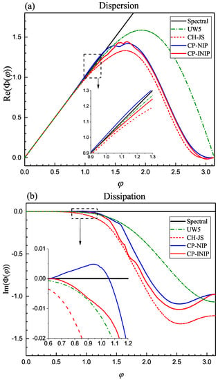
Figure 1.
Comparison of the dispersion and dissipation properties of different schemes. (a) Dispersion. (b) Dissipation.
4. Numerical Tests and Discussion
In this section, the numerical performances of the proposed CP-INIP scheme is compared with the CH-JS, CH-NIP and CP-NIP schemes by solving several 1D and 2D benchmark tests governed by the system of Euler equations.
The presentation of the numerical examples in this section starts with the accuracy test of the one-dimensional smooth density perturbation advection problem [33] with two different initial conditions, followed by several widely simulated 1D problems of Euler equations, including the shock-tube problems of Lax [40] and Sod [41], the Woodward–Colella interacting blast waves [42], the shock-entropy wave problem of Shu and Osher [26], and the Leblanc shock tube problem [43,44,45]. To finish this section, five famous 2D problems of Euler equations are simulated, such as the two-dimensional Riemann problem [46], shock-vortex interaction [47,48], regular shock reflection [49], double Mach reflection of a strong shock [42] and forward facing step problem [42]. In all calculations below, is taken to be for all schemes following the recommendations in [2,5].
For time evaluation in Equation (4), the following third-order total variation diminishing (TVD) Runge–Kutta approach [34,35,36]
where is the spatial operator taking the following form with respect to
and , are the intermediate stages, is the value of u at time level , are used in the following numerical tests for evaluating the approximate solution using different WENO schemes.
To ensure a physical solution, it is essential that the physical flow information is received by all cells within the calculation domain. Therefore, it needs to be guaranteed that the information transport does not overtake the physical transport, otherwise the scheme will be unable to access the information required to form the solution. The above criteria is known as the Courant-Friedrichs-Lewy (CFL) condition [50,51], and it is a necessary condition for convergence. For instance, in one-dimensional cases, it can be written as
where is the characteristic velocity, is the time step and is the spatial step. The key dimensionless number here is the Courant number, CFL, which needs to be less or equal to 1. In this paper, the CFL number is set to be unless stated otherwise.
4.1. Convergence Property
Firstly, the convergence properties of various considered WENO schemes are examined by solving the 1D smooth density perturbation advection problem [33] modeled via the 1D system of Euler equations.
It should be pointed out that the CFL number is taken to be to eliminate the influence of the time-integration procedure here. As is known, for the third-order Runge–Kutta method [34,35,36], the rate of the temporal convergence is . The CFL number is defined by , and hence with here. Thus, since only the fifth-order methods are considered here, and to ensure that the error for the overall scheme is a measure of the spatial convergence only, the CFL number is taken to be . Let be the numerical solution and be the exact solution. Then, the and errors of the density are calculated by
The corresponding convergence rates of accuracy of different schemes are also calculated.
Example 1.
Let , the initial conditions are given by
with the exact solutions taking the form
The solutions are marched to in the domain with periodic boundary conditions.
The numerical errors and the corresponding convergence rates of accuracy of the density obtained from various considered WENO schemes are presented in Table 1 and Table 2 for IC1 and IC2, respectively. It can be seen that the formal convergence rates of accuracy for IC1 are obtained by all considered WENO schemes. However, for IC2, the CH-JS scheme can not achieve the formal convergence orders, while the proposed CP-INIP scheme, as well as the CH-NIP and CP-NIP schemes, can successfully recover the formal convergence orders. Moreover, for both IC1 and IC2, the numerical errors of the proposed CP-INIP scheme are almost identical to those of the CP-NIP and CH-NIP schemes and they are significantly smaller than those of the CH-JS scheme.

Table 1.
The numerical errors and convergence orders of the density for various considered WENO schemes for IC1.
Table 1.
The numerical errors and convergence orders of the density for various considered WENO schemes for IC1.
| N | CH-JS | CH-NIP | ||||||
| Error | Order | Error | Order | Error | Order | Error | Order | |
| 100 | 4.25394 | - | 4.00551 | - | 6.11367 | - | 4.79993 | - |
| 120 | 1.70927 | 5.0009 | 1.61387 | 4.9859 | 2.45755 | 4.9987 | 1.92973 | 4.9979 |
| 140 | 7.90731 | 5.0007 | 7.45887 | 5.0069 | 1.13719 | 4.9990 | 8.93028 | 4.9985 |
| 160 | 4.05543 | 5.0006 | 3.81502 | 5.0210 | 5.83322 | 4.9994 | 4.58125 | 4.9986 |
| 180 | 2.25035 | 5.0005 | 2.10934 | 5.0310 | 3.23716 | 4.9996 | 2.54272 | 4.9985 |
| 200 | 1.32875 | 5.0004 | 1.24050 | 5.0385 | 1.91151 | 5.0000 | 1.50180 | 4.9978 |
| CP-NIP | CP-INIP | |||||||
| Error | Order | Error | Order | Error | Order | Error | Order | |
| 100 | 6.11367 | - | 4.79993 | - | 6.11367 | - | 4.79993 | - |
| 120 | 2.45755 | 4.9987 | 1.92972 | 4.9979 | 2.45755 | 4.9987 | 1.92972 | 4.9979 |
| 140 | 1.13719 | 4.9990 | 8.93028 | 4.9984 | 1.13719 | 4.9990 | 8.93028 | 4.9984 |
| 160 | 5.83323 | 4.9994 | 4.58125 | 4.9986 | 5.83323 | 4.9994 | 4.58125 | 4.9986 |
| 180 | 3.23716 | 4.9997 | 2.54273 | 4.9985 | 3.23716 | 4.9997 | 2.54273 | 4.9985 |
| 200 | 1.91151 | 5.0000 | 1.50179 | 4.9979 | 1.91151 | 5.0000 | 1.50179 | 4.9979 |

Table 2.
The numerical errors and convergence orders of the density for various considered WENO schemes for IC2.
Table 2.
The numerical errors and convergence orders of the density for various considered WENO schemes for IC2.
| N | CH-JS | CH-NIP | ||||||
| Error | Order | Error | Order | Error | Order | Error | Order | |
| 100 | 5.32486 | - | 1.48462 × 10⁻⁵ | - | 7.08156 | - | 9.93975 | - |
| 120 | 2.38894 | 4.3963 | 7.96379 | 3.4162 | 2.85032 | 4.9915 | 4.00304 | 4.9884 |
| 140 | 1.21522 | 4.3848 | 4.72887 | 3.3812 | 1.31989 | 4.9944 | 1.85431 | 4.9921 |
| 160 | 6.77367 | 4.3770 | 3.02134 | 3.3549 | 6.77491 | 4.9944 | 9.51826 | 4.9942 |
| 180 | 4.04031 | 4.3871 | 2.03984 | 3.3352 | 3.76133 | 4.9961 | 5.28618 | 4.9932 |
| 200 | 2.55079 | 4.3652 | 1.43767 | 3.3205 | 2.22168 | 4.9972 | 3.12272 | 4.9961 |
| CP-NIP | CP-INIP | |||||||
| Error | Order | Error | Order | Error | Order | Error | Order | |
| 100 | 7.08156 | - | 9.93975 | - | 7.08156 | - | 9.93975 | - |
| 120 | 2.85032 | 4.9915 | 4.00303 | 4.9884 | 2.85032 | 4.9915 | 4.00303 | 4.9884 |
| 140 | 1.31989 | 4.9944 | 1.85431 | 4.9921 | 1.31989 | 4.9944 | 1.85431 | 4.9921 |
| 160 | 6.77491 | 4.9944 | 9.51826 | 4.9942 | 6.77491 | 4.9944 | 9.51826 | 4.9942 |
| 180 | 3.76133 | 4.9961 | 5.28618 | 4.9932 | 3.76133 | 4.9961 | 5.28618 | 4.9932 |
| 200 | 2.22168 | 4.9972 | 3.12273 | 4.9961 | 2.22168 | 4.9972 | 3.12273 | 4.9961 |
4.2. One-Dimensional Euler System
Example 2.
Shock-tube problem of Lax [40].
The initial conditions are given by
and the solutions are advanced to with transmissive boundary conditions at .
The profiles of density obtained using the CP-INIP, CP-NIP and CH-NIP schemes are plotted in Figure 2. A series of uniform cells with are considered. Obviously, the CP-NIP scheme produces severe spurious oscillations for all considered computing cases with different cells. However, the oscillations have been greatly reduced in the numerical results of the proposed CP-INIP scheme. As a matter of fact, the CP-INIP scheme can not eliminate the oscillations thoroughly, while its oscillations are much smaller in amplitude and far less in number than the CP-NIP scheme. To this test, the CH-NIP scheme appears to be more robust compared to both CP-NIP and CP-INIP in the price of performing the expensive and complicated characteristic decomposition.
Example 3.
Shock-tube problem of Sod [41].
The initial conditions are given by
and the solutions are advanced to with transmissive boundary conditions at .
The profiles of density obtained using the CP-INIP, CP-NIP and CH-NIP schemes are presented in Figure 3. A series of uniform cells with are considered. For the sake of brevity though, only the zoomed results for the cases of are shown. As before, it is clear that the CP-NIP scheme displays obvious spurious oscillations for all considered computing cases with different cells while the proposed CP-INIP scheme has removed these oscillations remarkably. Furthermore and surprisingly, for this test, the CH-NIP scheme also produces evident spurious oscillations which are much severer than those of the CP-INIP scheme.
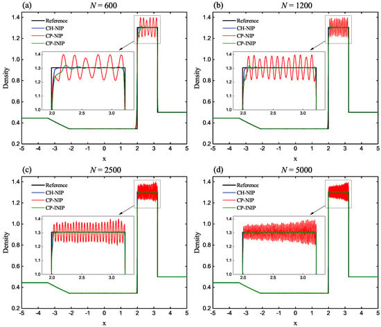
Figure 2.
Numerical solutions of the CP-INIP, CP-NIP and CH-NIP schemes for the shock-tube problem of Lax at output time . (a) 600 cells. (b) 1200 cells. (c) 2500 cells. (d) 5000 cells.
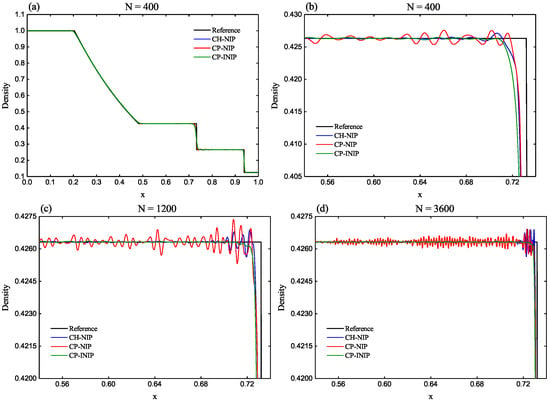
Figure 3.
Numerical solutions of the CP-INIP, CP-NIP and CH-NIP schemes for the shock-tube problem of Sod at output time . (a) Full view for 400 cells. (b) Zoomed-in view for 400 cells. (c) Zoomed-in view for 1200 cells. (d) Zoomed-in view for 3600 cells.
Example 4.
Woodward–Colella’s interacting blast waves [42].
The initial conditions are given by
and the solutions are advanced to with reflective boundary conditions at .
The profiles of density computed by CP-INIP, CP-NIP and CH-NIP schemes are shown in Figure 4. For the purpose of comparison, the result of the CH-JS scheme is also presented. Firstly, the solution of the CH-NIP scheme blows up for this example. The solution of the CP-NIP scheme does not blow up while it produces very severe spurious oscillations. Fortunately, the proposed CP-INIP scheme can properly simulate this example without generating numerical oscillations, and it has better resolutions than the CH-JS scheme.
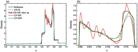
Figure 4.
Numerical solutions of the CP-INIP, CP-NIP and CH-NIP schemes for the Woodward-Colella’s interacting blast waves at output time . (a) Full view. (b) Zoomed-in view.
Example 5.
The shock-entropy wave problem of Shu and Osher [26].
The initial conditions are given by
and the solutions are advanced to with transmissive boundary conditions at .
The profiles of density computed by CP-INIP, CP-NIP and CH-NIP schemes are displayed in Figure 5. In addition, the result of the CH-JS scheme is plotted. The reference solution is obtained by using the CH-JS scheme with N = 10,000 uniform cells. Obviously, the CP-NIP scheme leads to overshoots of the post-shock waves. However, the proposed CP-INIP scheme can properly amend this drawback. In addition, the proposed CP-INIP scheme gets higher resolution than the CH-NIP scheme that outperforms the CH-JS scheme.

Figure 5.
Numerical solutions of the CP-INIP, CP-NIP, CH-NIP and CH-JS schemes for the shock-entropy wave problem of Shu and Osher at output time . (a) Full view. (b) Zoomed-in view behind the high-frequency waves. (c) Zoomed-in view of the high-frequency waves.
Example 6.
The Leblanc shock tube problem [43,44,45].
This is an extreme shock tube problem and the computational domain is filled with a perfect gas with . The initial conditions are given by
and the solutions are advanced to with transmissive boundary conditions at .
The profiles of density and internal energy computed by CP-INIP, CP-NIP and CH-NIP schemes are shown in Figure 6. As before, the results of the CH-JS scheme is also plotted. It can be found that the solutions of the CH-NIP and CP-NIP schemes blow up for this extreme shock tube test. However, the CP-INIP scheme can successfully simulate this test. Moreover, by comparing with the exact solution, it can be seen that the position of the shock from the results of the CP-INIP scheme can be maintained better than that of the CH-JS scheme, albeit slightly.
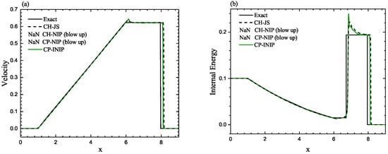
Figure 6.
Numerical solutions of the CP-INIP, CP-NIP, CH-NIP and CH-JS schemes for the Leblanc shock tube problem at output time . (a) Velocity. (b) Internal energy.
4.3. Two-Dimensional Euler System
Example 7.
Two-dimensional Riemann problem [46].
Let . The initial conditions of the benchmark case 13 of the two-dimensional Riemann problem classified by Lax and Liu [46] for ideal gas are given as
and the numerical results are computed till with transmission boundary conditions on all edges.
In Figure 7, the density contours of the CP-NIP and CP-INIP schemes are displayed, as well as the cross-sectional slices at for three set meshes of , and . In the third row of Figure 7, the reference solution is obtained using the CH-JS scheme with a refined mesh of . It can be observed that there are severe spurious oscillations on the contours of the CP-NIP scheme. However, it can be found that the proposed CP-INIP scheme can properly eliminate or significantly reduce these spurious oscillations. Additionally, this can also be further demonstrated from the cross-sectional slices as shown in the last row of Figure 7.
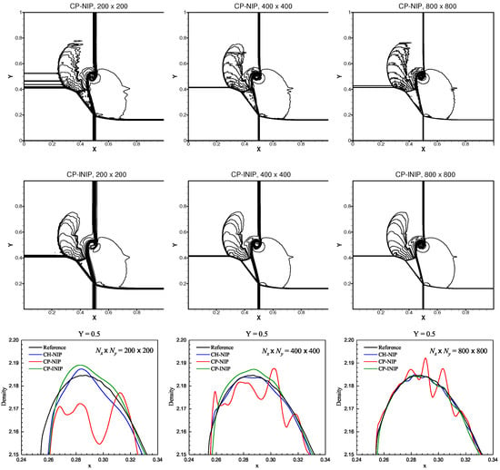
Figure 7.
Numerical solutions of the density of the 2D Riemann problem at . From top to bottom rows: solutions of the CP-NIP, CP-INIP schemes and the cross-sectional slices at . From left to right columns: and uniform cells.
Example 8.
Shock-vortex interaction [47,48].
The initial conditions of the widely-used shock-vortex interaction are given as
where and , with
and . The numerical results are computed till with transmission boundary conditions on all edges.
In Figure 8, the density contours of the CP-NIP and CP-INIP schemes are presented, as well as the cross-sectional slices at for three set meshes of and . As before, it can be seen that there are violent spurious oscillations on the contours of the CP-NIP scheme. As expected, the proposed CP-INIP scheme can successfully remove or greatly decrease these spurious oscillations. Moreover, this is further illustrated by taking a closer inspection from the last row of Figure 8 in which the reference solution is computed using the CH-JS scheme with a refined mesh of . For comparison purposes, the results of the CH-NIP scheme is also plotted. Clearly, both the CP-NIP and CH-NIP schemes suffer badly from the spurious oscillations while it can be seen that the spurious oscillations of the curves of the CP-INIP scheme are much more moderate.
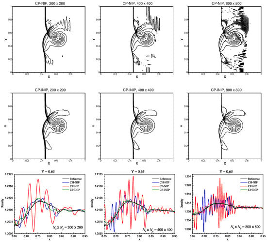
Figure 8.
Numerical solutions of the density of the shock-vortex interaction at . From top to bottom rows: solutions of the CP-NIP, CP-INIP schemes and the cross-sectional slices at . From left to right columns: and uniform cells.
Example 9.
Regular shock reflection [49].
The initial conditions of this typical 2D steady flow benchmark test are given as
The reflective and transmissive boundary conditions are used on the bottom and right edges, respectively. On the top and left edges, the Dirichlet boundary conditions are given as follows
The numerical results are advanced to unless indicated otherwise.
The density contours solved by the CP-NIP and CP-INIP schemes with three set meshes of , and uniform cells are shown in the first three rows of Figure 9. Firstly, for the computing cases of and uniform cells, it is evident that the CP-NIP scheme produces much severer spurious oscillations while the proposed CP-INIP scheme can significantly reduce these oscillations. Moreover, for the computing case of , it is found that the calculation of the CP-NIP scheme blows up at around as shown in the left of the third row in Figure 9. However, the proposed CP-INIP scheme can successfully avoid this blow-up problem and properly perform the calculation to the final output time . As before, from the cross-sectional slices at as shown in the last row of Figure 9, where the reference solution is obtained using the well-validated CH-ZS scheme [49] with a refined mesh of , it can be observed clearly that both the CP-NIP and CH-NIP schemes severely suffer from the spurious oscillations while the spurious oscillations of the curves of the CP-INIP scheme are much more moderate.
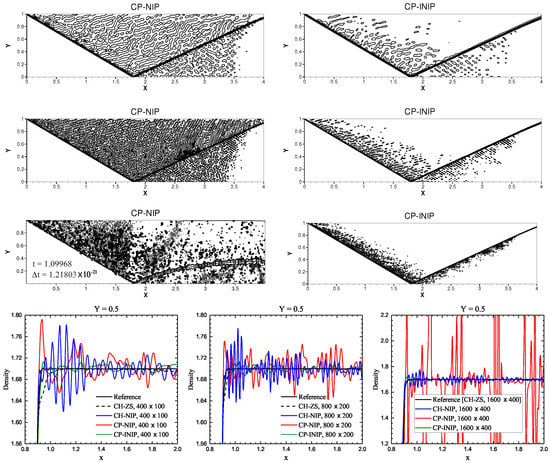
Figure 9.
Numerical solutions of the density of the regular shock reflection at . From left to right columns: solutions of the CP-NIP and CP-INIP schemes. From top to bottom rows: , uniform cells (the first three rows), and the cross-sectional slices at (the last row).
Example 10.
Double Mach reflection of a strong shock [42].
The initial conditions of this famous benchmark test are given as
On , as well as the region over along , the post-shock values as given above are imposed, and on , the zero gradient outflow condition is employed. The reflective boundary condition is used over the region . On , the exact motion of the Mach 10 shock is described by the following boundary condition
with , which is the position of the shock wave at time t on the top boundary. The solutions are advanced to unless indicated otherwise.
The density contours simulated by the CP-NIP and CP-INIP schemes with three set of and uniform cells are displayed in Figure 10. Again, for the computing cases of and uniform cells, it is clear that the CP-NIP scheme generates much severer non-physical post-shock oscillations. However, the proposed CP-INIP scheme can greatly decrease these post-shock oscillations to a tolerable level. Furthermore, for the computing case of , the solution of the CP-NIP scheme blows up at around as shown in the left of the last row in Figure 10. As before, it is found that the proposed CP-INIP scheme can successfully avoid this blow-up problem and properly make the calculation to the final output time .
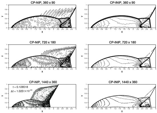
Figure 10.
Numerical solutions of the density of the double Mach reflection of a strong shock at . From left to right columns: solutions of the CP-NIP and CP-INIP schemes. From top to bottom rows: , uniform cells.
Example 11.
Forward facing step problem [42].
This example is also a very famous benchmark test and its initial conditions are given as
The reflective boundary conditions are used along all walls. On the left and right edges, the inflow and outflow conditions are used, respectively. The solutions are advanced to . The readers are referred to [42] for detailed descriptions of the forward facing step problem.
This example is simulated using CP-NIP, CH-NIP and CP-INIP schemes with various uniform cells such as and . It should be pointed out that the solutions of the CP-NIP scheme for all considered meshes have blown up, and also, the solutions of the CH-NIP scheme for the computing cases of and uniform cells have blown up. Therefore, only the density contours simulated by the CH-NIP and CP-INIP schemes with and uniform cells are displayed in the first two rows of Figure 11 and the solutions of the CP-INIP scheme with and uniform cells are displayed in the last row of Figure 11. Clearly, the proposed CP-INIP scheme can properly simulate this benchmark test without blowing up. Moreover, compared to the CH-NIP scheme, the CP-INIP scheme is far less oscillatory as shown in the first two rows of Figure 11. Actually, as mentioned above, when the meshes get larger, such as using and uniform cells, the calculations of the CH-NIP scheme have blown up, while the CP-INIP scheme still performs very well.
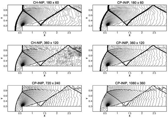
Figure 11.
Numerical solutions of the density of the forward facing step problem . From top to bottom rows: , and uniform cells.
5. Conclusions
In this article, the CP-WENO-NIP scheme was improved by introducing an additional term into its nonlinear weights formula to remove the negative-dissipation interval of its spectral property. The convergence property of the improved scheme, dubbed CP-WENO-INIP, is almost identical to that of the corresponding CP-WENO-NIP and CH-WENO-NIP schemes. Simulations of extensive numerical examples of 1D and 2D Euler problems indicate that the proposed CP-WENO-INIP scheme significantly outperforms the CP-WENO-NIP and CH-WENO-NIP schemes. Compared to the CP-WENO-NIP scheme, the CP-WENO-INIP scheme can eliminate or greatly reduce the spurious oscillations. Moreover, compared to the CH-WENO-NIP scheme, the CP-WENO-INIP scheme still performs better for most computing cases. Therefore, with better robustness, the proposed CP-WENO-INIP scheme is more particularly applicable for compressible flow simulations than the compared schemes, especially for the cases with large scale or highly complex eigenstructures.
In the future, the proposed WENO scheme can be used to the traffic flow model [27,52], the polydisperse sedimentation models [28,31], the multi-species kinematic flow model [53], the magnetohydrodynamics system [29] and the delayed systems [54,55]. As an open problem, an investigation of introducing computational intelligence into the proposed WENO scheme by exploiting the efficiency of artificial neural networks (ANN) [56] or Gudermannian neural networks (GNN) [57] is our possible future study.
Author Contributions
Conceptualization, R.L. and W.Z.; Formal analysis, W.Z.; Investigation, W.Z.; Methodology, W.Z.; Supervision, R.L.; Writing—original draft, W.Z.; Writing—review & editing, R.L. and W.Z. All authors have read and agreed to the published version of the manuscript.
Funding
This research received no external funding.
Data Availability Statement
Not applicable.
Conflicts of Interest
The authors declare no conflict of interest.
References
- Jiang, G.S.; Shu, C.W. Efficient implementation of weighted ENO schemes. J. Comput. Phys. 1996, 126, 202–228. [Google Scholar] [CrossRef]
- Henrick, A.K.; Aslam, T.D.; Powers, J.M. Mapped weighted essentially non-oscillatory schemes: Achieving optimal order near critical points. J. Comput. Phys. 2005, 207, 542–567. [Google Scholar] [CrossRef]
- Borges, R.; Carmona, M.; Costa, B.; Don, W.S. An improved weighted essentially non-oscillatory scheme for hyperbolic conservation laws. J. Comput. Phys. 2008, 227, 3191–3211. [Google Scholar] [CrossRef]
- Feng, H.; Hu, F.; Wang, R. A new mapped weighted essentially non-oscillatory scheme. J. Sci. Comput. 2012, 51, 449–473. [Google Scholar] [CrossRef]
- Feng, H.; Huang, C.; Wang, R. An improved mapped weighted essentially non-oscillatory scheme. Appl. Math. Comput. 2014, 232, 453–468. [Google Scholar] [CrossRef]
- Wang, R.; Feng, H.; Huang, C. A New Mapped Weighted Essentially Non-oscillatory Method Using Rational Function. J. Sci. Comput. 2016, 67, 540–580. [Google Scholar] [CrossRef]
- Yuan, M. A new weighted essentially non-oscillatory WENO-NIP scheme for hyperbolic conservation laws. Comput. Fluids 2020, 197, 104168. [Google Scholar] [CrossRef]
- Li, R.; Zhong, W. A Modified Adaptive Improved Mapped WENO Method. Commun. Comput. Phys. 2021, 30, 1545–1588. [Google Scholar]
- Li, R.; Zhong, W. An Efficient Mapped WENO Scheme Using Approximate Constant Mapping. Numer. Math. Theor. Meth. Appl. 2022, 15, 1–41. [Google Scholar] [CrossRef]
- Li, R.; Zhong, W. A New Mapped WENO Scheme Using Order-Preserving Mapping. Commun. Comput. Phys. 2022, 31, 548–592. [Google Scholar] [CrossRef]
- Li, R.; Zhong, W. Towards Building the OP-Mapped WENO Schemes: A General Methodology. Math. Comput. Appl. 2021, 26, 67. [Google Scholar] [CrossRef]
- Li, R.; Zhong, W. An Extension of the Order-Preserving Mapping to the WENO-Z-type Schemes. arXiv 2022, arXiv:2110.13607. [Google Scholar]
- Li, R.; Zhong, W. A General Improvement in the WENO-Z-type Schemes. Commun. Comput. Phys. 2022, 31, 1362–1401. [Google Scholar] [CrossRef]
- Chen, J.; Cai, X.; Qiu, J.; Qiu, J.M. Adaptive Order WENO Reconstructions for the Semi-Lagrangian Finite Difference Scheme for Advection Problem. Commun. Comput. Phys. 2021, 30, 67–96. [Google Scholar] [CrossRef]
- Zhu, J.; Shu, C.W.; Qiu, J. High-Order Runge–Kutta Discontinuous Galerkin Methods with a New Type of Multi-Resolution WENO Limiters on Tetrahedral Meshes. Commun. Comput. Phys. 2021, 29, 1030–1058. [Google Scholar] [CrossRef]
- Li, R.; Zhong, W. Improvement of the WENO-NIP Scheme for Hyperbolic Conservation Laws. Axioms 2022, 11, 190. [Google Scholar] [CrossRef]
- Ji, X.; Xu, K. A Performance Enhancement for High-Order Gas-Kinetic Scheme Based on WENO-Adaptive-Order Reconstruction. Commun. Comput. Phys. 2020, 28, 539–590. [Google Scholar]
- Sun, Y.; Shi, Y.; Xu, G. Application of High-Order WENO Scheme in the CFD/FW–H Method to Predict Helicopter Rotor Blade–Vortex Interaction Tonal Noise. Aerospace 2022, 9, 196. [Google Scholar] [CrossRef]
- Huang, Z.; Zheng, S.; Deng, X. A New ϵ-Adaptive Algorithm for Improving Weighted Compact Nonlinear Scheme with Applications. Aerospace 2022, 9, 369. [Google Scholar] [CrossRef]
- Pei, W.; Jiang, Y.; Li, S. A High-Order CFD Solvers on Three-Dimensional Unstructured Meshes: Parallel Implementation of RKDG Method with WENO Limiter and Momentum Sources. Aerospace 2022, 9, 372. [Google Scholar] [CrossRef]
- Antona, R.; Vacondio, R.; Avesani, D.; Righetti, M.; Renzi, M. Towards a High Order Convergent ALE-SPH Scheme with Efficient WENO Spatial Reconstruction. Water 2021, 13, 2432. [Google Scholar] [CrossRef]
- Chen, S. Krylov SSP Integrating Factor Runge–Kutta WENO Methods. Mathematics 2021, 9, 1483. [Google Scholar] [CrossRef]
- Musa, O.; Huang, G.; Wang, M. A New Smoothness Indicator of Adaptive Order Weighted Essentially Non-Oscillatory Scheme for Hyperbolic Conservation Laws. Mathematics 2021, 9, 69. [Google Scholar] [CrossRef]
- Guo, W.; Lin, G.; Christlieb, A.J.; Qiu, J. An Adaptive WENO Collocation Method for Differential Equations with Random Coefficients. Mathematics 2016, 4, 29. [Google Scholar] [CrossRef]
- Dong, H.; Lu, C.; Yang, H. The Finite Volume WENO with Lax–Wendroff Scheme for Nonlinear System of Euler Equations. Mathematics 2018, 6, 211. [Google Scholar] [CrossRef]
- Shu, C.W.; Osher, S. Efficient implementation of essentially non-oscillatory shock-capturing schemes II. J. Comput. Phys. 1989, 83, 32–78. [Google Scholar] [CrossRef]
- Zhang, M.; Shu, C.W.; Wong, G.C.K.; Wong, S.C. A weighted essentially non-oscillatory numerical scheme for a multi-class Lighthill–Whitham–Richards traffic flow model. J. Comput. Phys. 2003, 191, 639–659. [Google Scholar] [CrossRef]
- Marti, M.C.; Mulet, P. Some techniques for improving the resolution of finite difference component-wise WENO schemes for polydisperse sedimentation models. Appl. Numer. Math. 2014, 78, 1–13. [Google Scholar] [CrossRef]
- Do, S.; Li, H.; Kang, M. Wavelet-based adaptation methodology combined with finite difference WENO to solve ideal magnetohydrodynamics. J. Comput. Phys. 2017, 17, 482–499. [Google Scholar] [CrossRef]
- Hu, X.Y.; Wang, B.; Adams, N.A. An efficient low-dissipation hybrid weighted essentially non-oscillatory scheme. J. Comput. Phys. 2015, 301, 415–424. [Google Scholar] [CrossRef]
- Chiavassa, G.; Marti, M.C.; Mulet, P. Hybrid WENO schemes for polydisperse sedimentation models. Int. J. Comput. Math. 2016, 93, 1801–1817. [Google Scholar] [CrossRef]
- Li, R.; Zhong, W. A robust and efficient component-wise WENO scheme for Euler equations. Appl. Math. Comput. 2023, 438, 127583. [Google Scholar] [CrossRef]
- Peng, J.; Zhai, C.; Ni, G.; Yong, H.; Shen, Y. An adaptive characteristic-wise reconstruction WENO-Z scheme for gas dynamic Euler equations. Comput. Fluids 2019, 179, 34–51. [Google Scholar] [CrossRef]
- Shu, C.W.; Osher, S. Efficient implementation of essentially non-oscillatory shock-capturing schemes. J. Comput. Phys. 1988, 77, 439–471. [Google Scholar] [CrossRef]
- Gottlieb, S.; Shu, C.W. Total variation diminishing Runge–Kutta schemes. Math. Comput. 1998, 67, 73–85. [Google Scholar] [CrossRef]
- Gottlieb, S.; Shu, C.W.; Tadmor, E. Strong stability-preserving high-order time discretization methods. SIAM Rev. 2001, 43, 89–112. [Google Scholar] [CrossRef]
- Luo, X.; Wang, S. Improvement of the WENO-Z+ scheme. Comput. Fluids 2021, 218, 104855. [Google Scholar] [CrossRef]
- Acker, F.; Borges, R.D.R.; Costa, B. An improved WENO-Z scheme. J. Comput. Phys. 2016, 313, 726–753. [Google Scholar] [CrossRef]
- Pirozzoli, S. On the spectral properties of shock-capturing schemes. J. Comput. Phys. 2006, 219, 489–497. [Google Scholar] [CrossRef]
- Lax, P.D. Weak solutions of nonlinear hyperbolic equations and their numerical computation. Commun. Pure Appl. Math. 1954, 7, 159–193. [Google Scholar] [CrossRef]
- Sod, G.A. A survey of several finite difference methods for systems of nonlinear hyperbolic conservation laws. J. Comput. Phys. 1978, 27, 1–31. [Google Scholar] [CrossRef]
- Woodward, P.; Colella, P. The numerical simulation of two-dimensional fluid flow with strong shocks. J. Comput. Phys. 1984, 54, 115–173. [Google Scholar] [CrossRef]
- Cheng, J.; Shu, C.W. Positivity-preserving Lagrangian scheme for multi-material compressible flow. J. Comput. Phys. 2014, 257, 143–168. [Google Scholar] [CrossRef]
- Loubère, R.; Shashkov, M.J. A subcell remapping method on staggered polygonal grids for arbitrary-Lagrangian-Eulerian methods. J. Comput. Phys. 2005, 209, 105–138. [Google Scholar] [CrossRef]
- Liu, W.; Cheng, J.; Shu, C.W. High order conservative Lagrangian schemes with Lax-Wendroff type time discretization for the compressible Euler equations. J. Comput. Phys. 2009, 228, 8872–8891. [Google Scholar] [CrossRef]
- Lax, P.D.; Liu, X.D. Solution of two-dimensional Riemann problems of gas dynamics by positive schemes. SIAM J. Sci. Comput. 1998, 19, 319–340. [Google Scholar] [CrossRef]
- Chatterjee, A. Shock wave deformation in shock-vortex interactions. Shock Waves 1999, 9, 95–105. [Google Scholar] [CrossRef]
- Ren, Y.X.; Liu, M.; Zhang, H. A characteristic-wise hybrid compact-WENO scheme for solving hyperbolic conservation laws. J. Comput. Phys. 2003, 192, 365–386. [Google Scholar] [CrossRef]
- Zhang, S.; Shu, C.W. A new smoothness indicator for the WENO schemes and its effect on the convergence to steady state solutions. J. Sci. Comput. 2007, 31, 273–305. [Google Scholar] [CrossRef]
- Courant, R.; Friedrichs, K.; Lewy, H. On the Partial Difference Equations of Mathematical Physics. IBM J. Res. Dev. 1967, 11, 215–234. [Google Scholar] [CrossRef]
- Toro, E.F. Riemann Solvers and Numerical Methods for Fluid Dynamics—A Practical Introduction, 3rd ed.; Springer Science & Business Media: Berlin/Heidelberg, Germany, 2009; pp. 165–167. [Google Scholar]
- Zhang, P.; Wong, S.C.; Shu, C.W. A weighted essentially non-oscillatory numerical scheme for a multi-class traffic flow model on an inhomogeneous highway. J. Comput. Phys. 2006, 212, 739–756. [Google Scholar] [CrossRef]
- Burger, R.; Kozakevicius, A. Adaptive multiresolution WENO schemes for multi-species kinematic flow models. J. Comput. Phys. 2007, 224, 1190–1222. [Google Scholar] [CrossRef]
- Arbi, A.; Aouiti, C.; Touati, A. Uniform asymptotic stability and global asymptotic stability for time-delay Hopfield neural networks. In Proceedings of the IFIP International Conference on Artificial Intelligence Applications and Innovations, Halkidiki, Greece, 27–30 September 2012; Springer Science & Business Media: Berlin/Heidelberg, Germany, 2012; pp. 483–492. [Google Scholar]
- Arbi, A.; Tahri, N.; Jammazi, C.; Huang, C.; Cao, J. Almost anti-periodic solution of inertial neural networks with leakage and time-varying delays on timescales. Circuits Syst. Signal Process. 2022, 41, 1940–1956. [Google Scholar] [CrossRef]
- Sabir, Z.; Saoud, S.; Raja, M.A.Z.; Wahab, H.A.; Arbi, A. Heuristic computing technique for numerical solutions of nonlinear fourth order Emden–Fowler equation. Math. Comput. Simul. 2020, 178, 534–548. [Google Scholar] [CrossRef]
- Sabir, Z.; Raja, M.A.Z.; Arbi, A.; Altamirano, G.C.; Cao, J. Neuro-swarms intelligent computing using Gudermannian kernel for solving a class of second order Lane-Emden singular nonlinear model. AIMS Math. 2020, 6, 2468–2485. [Google Scholar] [CrossRef]
Publisher’s Note: MDPI stays neutral with regard to jurisdictional claims in published maps and institutional affiliations. |
© 2022 by the authors. Licensee MDPI, Basel, Switzerland. This article is an open access article distributed under the terms and conditions of the Creative Commons Attribution (CC BY) license (https://creativecommons.org/licenses/by/4.0/).