Abstract
The aim of the current numerical simulation was to understand the effects of the temperature-dependent properties of viscosity and thermal conductivity on the buoyant convection of cold water around its density extremum in a tilting chamber. The equations for thermal conductivity and viscosity were derived based on the reference temperature parameter. The entropy generation and cup mixing temperature were also calculated. The governing mathematical model was solved by the finite-volume-based iterative technique. The obtained results were deliberated for several values of inclination angles and for the density reversal parameter for variable viscosity and thermal conductivity cases. It was detected that density inversion has a strong effect on stream and thermal patterns through the development of a bi-cellular arrangement due to density inversion.
MSC:
76-10; 76D05; 76M12; 76R10; 80M12
1. Introduction
The convective flow of cold water around its density extremum () happens universally in the environment and in some engineering and technical processes [1,2,3]. Since the convective stream and thermal transfer of water around its density extremum is a complex phenomenon, experimental and theoretical investigations into the buoyant convective stream of water near its extreme density in a rectangular closed domain have been reported by many researchers [4,5,6,7]. Ho and Tu [8] (2001) numerically and experimentally inspected the free convective stream of water near its extreme density in a rectangular closed container. Moraga and Vega [9] (2004) scrutinized the variable physical properties of water in a 3D buoyant convection flow. Hossain and Rees [10] (2005) deliberated the unsteady laminar convective flow of water subject to density reversal in a rectangular chamber in the presence of (internal) heat generation. Sivasankaran and Ho [11,12,13] explored the effects of temperature-based water properties on the free convection of cold water near its density extreme region in a chamber. Varol et al. [14] made a numerical simulation to find an interesting result from the convective motion of (cold) water at 4 °C in a porous container with a thick bottom wall.
Li et al. [15] explored the three-dimensional Rayleigh–Bénard (RB) convection of water around its density extremum in a cylindrical domain with an aspect ratio of two. Hu et al. [16] experimentally and numerically examined the impact of aspect ratios on the Rayleigh–Bénard (RB) convective flow of (cold) water near its density supremum in cylindrical containers. They found that density inversion has a negative effect on heat transfer rates. Mastiani et al. [17] examined the density extremum effects of nano liquids on combined convection in a lid-driven chamber with various vertical wall movements. They used both non-Boussinesq and Boussinesq approximations in the study. Hua et al. [18] explored the effects of density inversion, aspect ratio, and thermal border conditions on the RB convection of cold water. Huang et al. [19] studied the effects of density inversion on Rayleigh–Bénard fluid motion and heat transfer in a cylindrical container. Hu et al. [20] explored the free convective flow of water-based nanofluids near their density inversions in an annulus. They established that Brownian motion must be taken into account when considering the free convection of water-based nanofluids at their density supremum. Bindhu et al. [21] explored the density inversion effect with various combinations of heater and cooler locations in a buoyant convective flow regime inside a square container. Sivasankaran et al. [22] found the impact of temperature-dependent water properties on buoyant flow around the density extreme region in a square chamber. From all these studies, we understand that flow around the vicinity of the density inversion point is more complicated and requires more detailed investigation.
In some situations, we have a thermal and mechanical system with a certain inclination from the ground (horizontal position). Therefore, it is essential that the flow and thermal transports in a tilted chamber are explored. Much research on the inclination of geometry under various conditions has been conducted during past three decades [23,24,25]. However, research exploring the effects of fluid properties in a tilted geometry is very limited. Cheng et al. [26] numerically deliberated the influence of tilting angles and aspect ratios on convective flow in a rectangular geometry with sinusoidal-type heating. Sivakumar and Sivasankaran [27] explored the impacts of nonuniform heating on mixed convection in a lid-driven inclined cavity. The impact of the direction of moving walls in a lid-driven geometry with sinusoidal heating was studied by Sivasankaran et al. [28]. The effects of various thermal border conditions on buoyant convection in an inclined triangular chamber was explored by Sivasankaran et al. [29]. Alshomrani et al. [30] inspected the influence of tiling angle, heater locations, and cooler locations on buoyant convection in a 3D box. Sivasankaran and Janagi [31] explored the effects of inclination and baffle size on mixed convective streams in a channel cavity.
The second law of thermodynamics explains the concept of entropy in a thermodynamic system. The analysis of entropy generation (EG) or irreversibility analysis is a key factor due to the calculation of energy loss, and EG can compute energy transmission and can estimate thermal performance. Since the irreversibility analysis exists on both due to fluid flow and thermal transport [32,33,34], numerous interdisciplinary sectors need to know about it in detail. Moreover, a reduction in EG is essential in order to save energy and improve the performance of the thermal system. Recently, investigations into entropy optimization have dramatically increased in the thermo-fluid field and its related disciplines. Many basic results on EG, with applications, have been derived by Bejan [35,36,37,38].
Alsabery et al. [39,40] explored entropy generation and convective flow hybrid nanofluids in a wavy walled container with a hot-half partition. They found that varying geometrical parameters induced different effects on entropy generation and Bejan number. Ghalambaz et al. [41] explored thermal convective transport and the entropy generation of hybrid nano liquids in an oddly shaped chamber. Khetib et al. [42] numerically explored the free convection and generation of entropy of nanofluids in a square inclined cavity under a constant magnetic field. They used three different fin configurations (straight, curved, and inclined) in order to analyze the results. Cherif et al. [43] explored heat transferal rates and the generation of entropy for a water-based hybrid nanofluid inside a 3D porous triangular-shaped cavity with a spinning cylinder. Alshare et al. [44], having performed numerical simulations, found an interesting result that thermal transport is responsible for entropy production when the magnetic and frictional effects are marginal. Le et al. [45], having examined entropy in the convection of nano-suspensions in a cavity, found that the addition of nanoparticles reduced the strength of heat transfer and diminished entropy generation. Abderrahmane et al. [46] deliberated the mixed convection and entropy generation of hybrid nanofluids in a 3D triangular enclosed area with a spinning circular cylinder in the middle of the domain. Mourad et al. [47] studied the MHD free convection and EG of (Cu–water) nano liquid in a porous annulus.
We have found that the convective flow of cold water with temperature-based physical properties in inclined cavities has not explored in previous research thus far. Hence, the current study inspects the influence of temperature-dependent viscosity and thermal conductivity of the water near its density extremum point on buoyant convection in a tilted cavity. The entropy generation and cup-mixing temperature are also explored here. The present research may be very useful for environmental thermal systems.
2. Mathematical Modelling
We studied a two-dimensional square chamber of size “D” that was filled with cold water, as shown in Figure 1. The isothermal vertical borders of the enclosed space were well preserved at dissimilar (constant) temperatures Th* and Tc*, with the condition that Th* > Tc*. The horizontal borders of the enclosed space were adiabatic. The gravitational force acted in a downwards direction. In the x and y directions, the velocity components u and v are given. The chamber was tilted to have an acute angle γ with the horizontal axis. The subsequent assumptions were adopted for this study: the flow is two-dimensional, unsteady, laminar, and incompressible. The Boussinesq approximation was valid. The viscous dissipation and radiation were neglected in this study. Water density has a non-linear relation with temperature, as follows [8,11]:
where β = 9.2971730 × 10⁻⁶, Tm = 4.0293250 °C, ρm (=999.9720) is the maximum density of water, and b = 1.894816. The thermal conductivity of water and the viscosity of water vary with temperature. The water viscosity varies with temperature, as follows [11,12]:
where a0 (=1.791084), a1 (=−6.144 × 10⁻²), a2 (=1.451 × 10⁻³), and a3 (=−1.6826 × 10⁻⁵) are the temperature quantities of the viscosity of water. Equation (2) can be written as:
where , , , and . The variable Tr denotes the reference temperature. ε denotes a parameter of the reference temperature, which plays an essential role on the water stream when variable properties are considered. The thermal conductivity of water [11,12,13] varies with temperature, as follows:
where b0 (=0.561965), b1 (=2.15346 × 10⁻³), b2 (=−1.55141 × 10⁻⁵), and b3 (=1.01689 × 10⁻⁷) are the temperature coefficients of the thermal conductivity of water. The equation can be written as:
where , , and .
μ(T*) = a0 + a1 T* + a2 T*2 + a3 T*3
k(T*) = b0 + b1 T* + b2 T*2 + b3 T*3
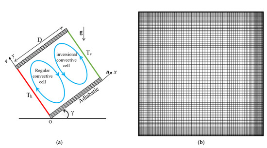
Figure 1.
Physical Configuration (a) and sample grid structure (b).
The governing equations of vorticity, stream function, and temperature with temperature-dependent liquid properties are:
where g denotes acceleration due to gravity, cp—specific heat, t—time, k—thermal conductivity, T—temperature, μ viscosity, and ρr—density.
The initial values are taken as , in the whole domain. The boundary conditions are as follows: the no-slip condition () for velocities was taken on all the solid walls at ,. The temperature conditions are at , at , and at .
The non-dimensional variables used here are given below.
The governing model equations after non-dimensionalization are:
The relation of velocity to stream function and vorticity are:
The dimensionless form of the initial values are: . The boundary conditions are:
The non-dimensional parameters that appear in the equations are: , the density inversion parameter; , the Rayleigh number; (=11.6), the Prandtl number. The density extremum parameter assisted us in tracing the maximum density plane inside the enclosed space. This was due to the existence of two dissimilar horizontal layers of water with dissimilar density gradients divided by the extreme density plane. values are between 0 and 1. Suppose , the hot (cool) barrier is at temperature so the density of water rises (declines) with temperature inside the domain. Computing the thermal gradient on a solid wall is vital in convective flow problems. The rate of heat transfer at the hot (left side) wall was measured using the local Nusselt number and is defined by . Then, the average Nusselt number is computed by: .
3. Entropy Generation
The EG was computed from well-known velocity and thermal fields because the entropy production resulted from the irreversible process of thermal transfer and viscosity effects. We can use the entropy generation values to discern the optimal settings for real world applications. The local EG (per unit area) was derived subject to heat transmission and fluid friction. That is, the total local EG was the sum of the two quantities (SGen = Sheat + Sfluid).
The dimensionless formula for EG is attained in a usual way:
The whole EG calculation is achieved by integrating the local EG over the enclosed region.
The local Bejan number gives the strength of the EG subject to the irreversibility of thermal transference. It is defined as:
It is interesting to note that heat transfer irreversibility dominates when . On the other hand, fluid friction irreversibility dominates when . The thermal and viscous irreversibilities are equal at . The mean Bejan number provides the relative impact of thermal current energy transfer irreversibility for the whole domain.
The final steady state values of the thermal and flow fields were taken to estimate the EG inside the enclosed area.
4. Thermal Mixing Analysis
The cup-mixing temperature was derived to determine thermal mixing in the enclosed space. The velocity-weighted mean temperature was more appropriate for convective currents than the spatial average temperature. The cup-mixing temperature (Tcup) is given as:
where .
The RMSD (Root Mean Square Deviation) was used to quantify the amount of temperature regularity. The RMSDTcup is defined based on the cup-mixing temperature values, as follows:
The lower values of RMSD specify greater temperature uniformity in the enclosed space and vice versa. The RMSD values cannot exceed unity because the dimensionless temperature diverges between 0 and 1.
5. Numerical Technique
The non-dimensional modelled Equations (9)–(12) with the initial and border conditions (13) are discretized by the control volume method. The diffusion terms were treated with the central difference scheme and the convective terms were treated with the upwind scheme. The physical domain was divided into a number of control volumes based on a non-uniform grid in both X and Y directions (Figure 1b). The grids were gathered near the walls of the chamber. The grid sizes were examined from 41 × 41 to 161 × 161 for Pr = 11.60, Ra = 106, and Tm = 0. It was perceived from the grid independence examination that a grid of size of 141 × 141 was adequate in order to explore the problem. The resulting algebraic equations were solved by the (Gauss-Seidel) iterative method using the successive over relaxation technique. This sequence was repeated until we reached the preferred accuracy for the convergence condition.
where “I” and “j” denote the grid nodes in X and Y directions, and the subscript “n” denotes the time step.
6. Validation
The computation was performed using ForTran in-house coding. The free convection of cold water near its density supremum with constant properties in a (square) cavity was taken for numerical verification. Since the validation of the in-house code is essential in research utilizing numerical simulations, the justifications for the current computational program were tested against the existing available results for free convection in a (square) cavity filled with cold water near its density supremum (Tong [5]; Lin and Nansteel [2]). The various values of Ra and Tm that were found are depicted in Table 1. A remarkable agreement was acquired between the current and previous values.

Table 1.
Comparison of results for the diverse density extremum parameter and Ra.
7. Results and Discussion
Numerical simulations exploring the buoyant convective flow of cold water around its density inversion point in an inclined chamber are made for a diverse combination of parameters with variable thermal conductivity and variable viscosity. The interaction of two mechanisms (namely, the inclination angle affecting geometry and buoyancy force due to the temperature gradients present in the body of the liquid) were explored in the present study. The effects result from two different phenomena. The goal of the present research was to inspect the interaction of these two effects on water current and heat transfer in the vicinity of inside the cavity with variable fluid properties. The range of the significant parameters were wisely scrutinized. The density reversal parameter diverged from 0 to 1, and the Rayleigh number was fixed at . The inclination angle varied from 0° to 90°. The reference temperature parameter diverged from 0.0 to 0.3.
Figure 2 demonstrates thermal spreading for the different values of the density inversion parameter and the tilting angle for variable thermal conductivity and variable viscosity cases. At , the density supreme plane was located at the hot wall. That is, there was no density reversal inside the chamber. There was a single clockwise eddy inside the container at . When the tilting angle was increased to , a single eddy stretched along the corner of the container. When the tilting angle was increased to and , we observed two inner eddies. When , the hot wall was located at the lower portion of the container. Three multi-cellular flow patterns existed, with two re-circulating eddies at the hot top and cold bottom corners of the container when . When , density inversion existed inside the container. That is, two dissimilar (horizontal) water layers formed with two dissimilar density gradients, divided by the density maximum plane. The dual cell structure of the stream was detected for all the tilting angles of the container. However, the size and strength of the eddies depended on the tilting angle. When , the cold cell occupied the majority of the container. However, the hot cell occupied the majority of the titled cavity. At , two equally strong eddies formed. The energy transfer from hot (left) wall to cold wall slowed down due to the dual cell pattern. This was because of the transfer of heat energy from one cell to the other cell by the conduction mode. After increasing the density inversion parameter value to , the density extremum plane was located at the cold wall. That is, there was no density reversal inside the chamber. A counter-rotating cell formed at this situation. When tilting the cavity, the cell stretched diagonally when , and two inner circulating cells formed inside the stretched eddy. When the tilting angle was further increased to , two strong counter-acting eddies formed inside the container. When , a tri-cellular pattern was observed. When comparing the cases of variable thermal conductivity and variable viscosity and thermal conductivity, the flow field had similar trends in most of the cases studied, except when and . Drastic changes to the flow field were found when and . The stream function value was lower for variable thermal conductivity case.
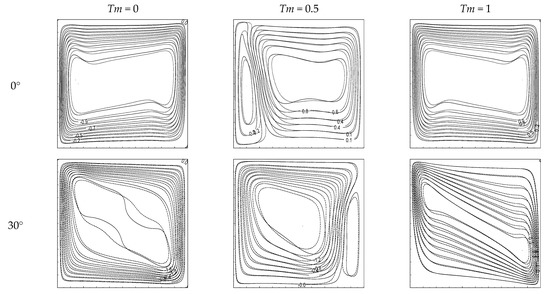
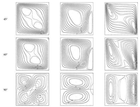
Figure 2.
Streamlines for various Tm, solid lines for , and dashed lines for both .
Figure 3 displays the thermal contours inside the container for various inclination angles, density inversion parameters, and both cases of variable thermal conductivity and variable viscosity. At and , vertical thermal stratification was observed. When increasing the tilting angle, thermal stratification disappeared. The thermal boundary layers along both isothermal walls were formed for all the inclination angle values at . A small difference in thermal distribution was found between the cases of variable thermal conductivity and the variable thermal conductivity and viscosity cases. When , the density maximum plane moved inside the cavity, and strong temperature gradients formed at the density maximum plane. The thermal boundary layers were not found along the isothermal walls at . In this situation, the density extremum plane was near the hot (left) wall. When titling the cavity (), the density extremum plane was near the cold (right) wall. When , the density extremum plane was in the middle of the cavity. The difference between the thermal distribution of the two cases was clearly visible at for all the tilting angles. When the () was increased further, the vertical thermal stratification was found for the vertical cavity (). When the tilting angle was changed, the thermal distribution was altered and vertical temperature stratification existed. However, the boundary layers disappeared when the cavity was tilted. At , the hot wall went down, which changed much of the flow and thermal fields. Here, the isotherms were almost straight lines and a conduction type of heat transfer was evident.
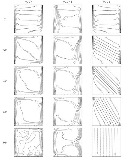
Figure 3.
Isotherms for various Tm and angles, with solid lines for and dashed lines for both .
Figure 4 demonstrates the time history of the averaged Nusselt numbers for the diverse values of and for the variable viscosity and variable thermal conductivity cases. Initially, the mean Nusselt number fell down and then reached a constant value after a specified time. A shorter time was taken to reach the steady state at . However, the time taken to reach the steady state was greater at . The average Nusselt number was initially overshot when . Figure 5 demonstrates the influence of local heat transfer for the various values of and with variable thermal conductivity and variable viscosity. The heat transfer attained a minimum value at for all the density inversion parameters. A higher local heat transfer rate was observed at . When increasing the values of from 0 to 1, the local heat transport rate initially declined and then increased later at . However, local heat transfer attained the lowest value at when . Local heat transfer declined when the values of were raised at . The local heat transfer rate was high at the bottom edge when , whereas it was high at the top edge of the cavity when . A similar trend was observed for . That is, the heat transport rate declined near the bottom edge of the cavity when the values of increased. However, the maximum value of local heat transfer was attained at the middle of the hot wall when .
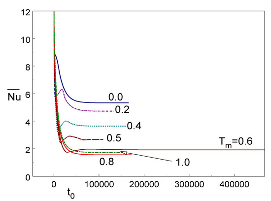
Figure 4.
Time history of the averaged Nusselt number for different values of Tm for both .
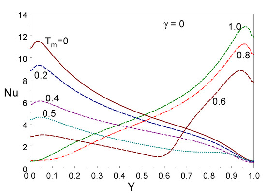
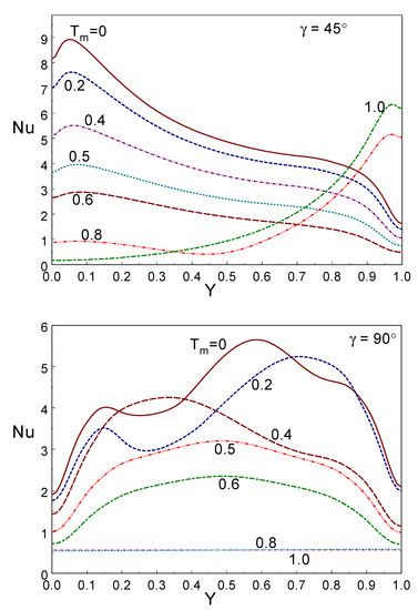
Figure 5.
Local Nusselt numbers for various values of Tm and angles for both .
Figure 6 displays the local heat transfer rate for various tilting angles and the for both cases of varying properties (viscosity and thermal conductivity cases). The local thermal transfer rate declined when the value of the tilting angle of the chamber was raised. The local heat transfer rate declined with the height of the wall at . That is, a higher local heat transfer was found at the lower portion of the hot wall at . However, the opposite trend was shown for the local heat transfer rate at . Furthermore, when inspecting these figures, a greater heat transfer was found to occur at compared to .
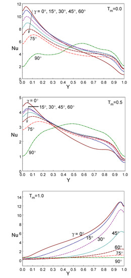
Figure 6.
Local Nusselt numbers for various tilting angles and values of Tm for both .
Figure 7a,b demonstrates the influence of averaged heat transfer rates for both cases with various values of inclination and different density inversion parameters. The averaged Nusselt number behaves non-linearly with the density reversal parameter. The minimum average heat transfer rate was obtained at when with changing values. For tilted cavities with , the average Nusselt number decreased when the value of was raised. Two different behaviours were observed between vertical and tilted cavities at the average Nusselt number. In the vertical cavity, the average Nusselt number declined at and then increased at . In comparing the two cases, the variable thermal conductivity case had a smaller high energy transfer rate than both the variable thermal conductivity and viscosity cases. While the vertical cavity gave a higher (lower) heat transfer rate at either or (), the tilted cavity () gave a higher (lower) heat transfer rate at (). The cavity with a lower tilting angle () behaved like a vertical cavity ().
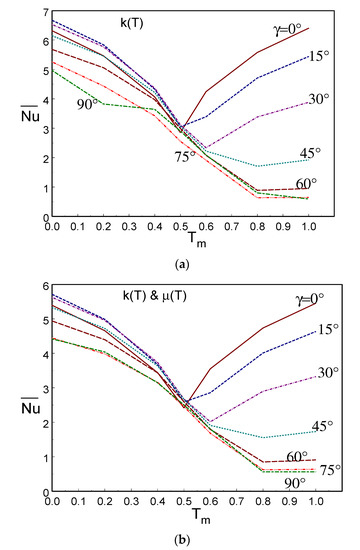
Figure 7.
Average Nusselt number versus the Tm of various tilting angles for (a) k(T) only and (b) both .
Figure 8a–d exposes the cup-mixing temperature and the RMSDTcup for various inclination angles and both variable thermal conductivity and viscosity cases. The cup-mixing temperature was high at and for the variable thermal conductivity case, whereas it was higher at and for both variable viscosity and thermal conductivity cases. When and , the cup-mixing temperature and its RMSDTcup was lower. Lower values of RMSD indicate good thermal (mixing) uniformity inside the enclosed region. RMSD never exceeded unity here. However, the RMSD values that are close to unity will not cope well with thermal mixing. In comparing both cases, only the variable thermal conductivity case provided better thermal mixing. When , the inclined cavity gave a higher temperature uniformity inside the enclosed region. The RMSD values of the vertical cavity ) were similar for all the values of . The RMSD values increased when the values of were raised in both cases.
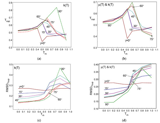
Figure 8.
Cup-mixing temperature (a,b) and RMSDTcup (c,d) versus Tm for various tilting angles.
Figure 9 depicts the entropy generation for various inclination angle values and density extremum parameters for the variable thermal conductivity and variable viscosity cases. The entropy generation was limited to a narrow boundary along the thermal walls for and all the values of . That is, strong entropy gradients were found along the isothermal walls. The generation of entropy happened near the boundary at and . When the inclination was increased, entropy generation was distributed inside the cavity. At , entropy generation existed throughout the cavity for all the inclination angles. These are interesting results to note. Entropy production was very strong near the vertical walls at and 0.5 for all the values of
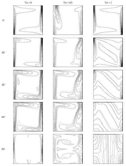
Figure 9.
Entropy generation for various values of Tm and various tilting angles, with solid lines for and dashed lines for both .
Figure 10 demonstrates the Bejan number versus for various inclination angle values with variable and both variable and cases. The Bejan number values were always above 0.65 for all the considered cases. This clearly indicates that entropy generation is dominant by heat transfer. The Bejan number increased whe the values of increased. The Bejan number was high (low) at when . However, the Bejan number was higher (a lower value) at when . In comparing both of these cases, the Bejan number was high for both the variable viscosity and variable thermal conductivity cases.
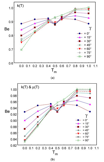
Figure 10.
Bejan number versus Tm for various tilting angles with (a) only and (b) both .
8. Conclusions
The influence of the tilting angle of the cavity, the variable viscosity and the variable thermal conductivity of cold water near its density supremum on free convection in an inclined closed chamber was investigated numerically. Cup-mixing temperature and entropy generation were also explored.
- ○
- The temperature-dependent equations for thermal conductivity and viscosity were derived with regards to the reference temperature parameter.
- ○
- The development of the dual cell arrangement and the strength of the cells depends on the density supremum parameter and inclination angle. The dual cell arrangement forbids convective thermal transfer across the chamber.
- ○
- The heat transfer rate for the variable thermal conductivity case was higher than the heat transfer rate for both of the varying cases.
- ○
- The rate of thermal transport performs nonlinearly with the density extremum parameter and the inclination angle. The mean heat transfer rate declines first and then increases when the density extremum parameter is raised when . However, it always declines when the density extremum parameter increases when .
- ○
- A small impact on the rate of thermal transport was found when the temperature difference parameter varied.
- ○
- The cup-mixing temperature behaves non-linearly with the density extremum parameter. RMSDTcup values are enhanced when the density extremum parameter values increase in both cases.
- ○
- The Bejan number increases when the density extremum parameter values increase. Entropy generation results can be used for the effective design of convective flow systems.
- ○
- The density extremum leaves a strong effect on the stream and the thermal distribution due to development of the bicellular arrangement. The dual cell arrangement directly prohibits the exchange of thermal energy between the hot region and the cold region. This results in a reduction in the average Nusselt number.
Author Contributions
Conceptualization, S.S.; methodology, S.S.; software, S.S.; validation, S.S.; formal analysis, S.S.; investigation, S.S.; writing—original draft preparation, S.S.; writing—review and editing, S.S. and F.O.M.M.; visualization, S.S.; supervision, S.S.; project administration, S.S.; funding acquisition, S.S. and F.O.M.M. All authors have read and agreed to the published version of the manuscript.
Funding
This research work was funded by the Institutional Fund Projects under Grant No. (IFPHI-276-130-2020).
Acknowledgments
This research work was funded by the Institutional Fund Projects under Grant No. (IFPHI-276-130-2020). The authors gratefully acknowledge the technical and financial support received from the Ministry of Education and King Abdulaziz University, DSR, Jeddah, Saudi Arabia.
Conflicts of Interest
The authors declare no conflict of interest.
References
- Joshi, Y.; Gebhart, B. Vertical transient natural convection flows in cold water. Int. J. Heat Mass Transf. 1984, 27, 1573–1582. [Google Scholar] [CrossRef]
- Lin, D.S.; Nansteel, M.W. Natural convection heat transfer in a square enclosure containing water near its density maximum. Int. J. Heat Mass Transf. 1987, 30, 2319–2329. [Google Scholar] [CrossRef]
- Braga, S.L.; Viskanta, R. Transient natural convection of water near its density extremum in a rectangular cavity. Int. J. Heat Mass Transf. 1992, 35, 861–875. [Google Scholar] [CrossRef]
- Wei, T.; Koster, J.N. Density inversion effect on transient natural convection in a rectangular enclosure. Int. J. Heat Mass Transf. 1994, 37, 927–938. [Google Scholar] [CrossRef]
- Tong, W. Aspect ratio effect on natural convection in water near its density maximum temperature. Int. J. Heat Fluid Flow 1999, 20, 624–633. [Google Scholar] [CrossRef]
- Ishikawa, M.; Hirata, T.; Noda, S. Numerical simulation of natural convection with density inversion in a square cavity. Numer. Heat Transf. Part A Appl. 2000, 37, 395–406. [Google Scholar]
- Sivasankaran, S. Natural Convection of Cold Water Near Its Density Maximum in a Porous Wavy Cavity. Flow Transp. Subsurf. Environ. 2018, 4, 305–324. [Google Scholar]
- Ho, C.J.; Tu, F.J. Visualization and prediction of natural convection of water near its density maximum in a tall rectangular enclosure at high Rayleigh numbers. J. Heat Transf. 2001, 123, 84–95. [Google Scholar] [CrossRef]
- Moraga, N.O.; Vega, S.A. Unsteady three-dimensional natural convection of water cooled inside a cubic enclosure. Numer. Heat Transf. Part A Appl. 2004, 45, 825–839. [Google Scholar] [CrossRef]
- Hossain, M.A.; Rees, D.A.S. Natural convection flow of water near its density maximum in a rectangular enclosure having isothermal walls with heat generation. Heat Mass Transf. 2005, 41, 367–374. [Google Scholar] [CrossRef]
- Sivasankaran, S.; Ho, C.J. Effect of temperature dependent properties on convection of water near its density maximum in enclosures. Numer. Heat Transf. Part A Appl. 2008, 53, 507–523. [Google Scholar] [CrossRef]
- Sivasankaran, S.; Ho, C.J. Effect of temperature dependent properties on MHD convection of water near its density maximum in a square cavity. Int. J. Therm. Sci. 2008, 47, 1184–1194. [Google Scholar] [CrossRef]
- Sivasankaran, S.; Ho, C.J. Buoyancy and thermo-capillary induced convection of cold water in an open enclosure with variable fluid properties. Numer. Heat Transf. Part A Appl. 2010, 58, 457–474. [Google Scholar] [CrossRef]
- Varol, Y.; Oztop, H.F.; Mobedi, M.; Pop, I. Visualization of heat flow using Bejan’s heatline due to natural convection of water near 4 °C in thick walled porous cavity. Int. J. Heat Mass Transf. 2010, 53, 1691–1698. [Google Scholar] [CrossRef]
- Li, Y.-R.; Hu, Y.-P.; Ouyang, Y.-Q.; Wu, C.-M. Flow state multiplicity in Rayleigh–Bénard convection of cold water with density maximum in a cylinder of aspect ratio 2. Int. J. Heat Mass Transf. 2015, 86, 244–257. [Google Scholar] [CrossRef]
- Hu, Y.-P.; Li, Y.-R.; Wu, C.-M. Aspect ratio dependence of Rayleigh–Bénard convection of cold water near its density maximum in vertical cylindrical containers. Int. J. Heat Mass Transf. 2016, 97, 932–942. [Google Scholar] [CrossRef]
- Mastiani, M.; Kim, M.M.; Nematollahi, A. Density maximum effects on mixed convection in a square lid-driven enclosure filled with Cu-water nanofluids. Adv. Powder Technol. 2017, 28, 197–214. [Google Scholar] [CrossRef]
- Hua, Y.-P.; Li, Y.-R.; Li, M.-H.; Zhang, L.; Li, S.-Z. Effects of enclosure geometry and thermal boundary condition on Rayleigh-Bénard convection of cold water near its maximum density. Int. J. Therm. Sci. 2017, 120, 220–232. [Google Scholar] [CrossRef]
- Huang, X.-J.; Li, Y.-R.; Zhang, L.; Wu, C.-M. Turbulent Rayleigh-Bénard convection of cold water near its maximum density in a vertical cylindrical container. Int. J. Heat Mass Transf. 2018, 116, 185–193. [Google Scholar] [CrossRef]
- Hu, Y.-P.; Li, Y.-R.; Lu, L.; Mao, Y.-J.; Li, M.-H. Natural convection of water-based nanofluids near the density maximum in an annulus. Int. J. Therm. Sci. 2020, 152, 106309. [Google Scholar] [CrossRef]
- Bindhu, R.; Sundarakrishnan, G.S.; Sivasankaran, S.; Bhuvaneswari, M. Magneto-convection of water near its maximum density in a cavity with partially thermally active walls. Energy Environ. 2019, 30, 833–853. [Google Scholar] [CrossRef]
- Sivasankaran, S.; Bhuvaneswari, M.; Kim, Y.J.; Ho, C.J.; Pan, K.L. Magneto-convection of cold water near its density maximum in an open cavity with variable fluid properties. Int. J. Heat Fluid Flow 2011, 32, 932–942. [Google Scholar] [CrossRef]
- Khan, U.; Waini, I.; Zaib, A.; Ishak, A.; Pop, I. MHD Mixed Convection Hybrid Nanofluids Flow over a Permeable Moving Inclined Flat Plate in the Presence of Thermophoretic and Radiative Heat Flux Effects. Mathematics 2022, 10, 1164. [Google Scholar] [CrossRef]
- Nabwey, H.A.; Alshber, S.I.; Rashad, A.M.; Mahdy, A.E.N. Influence of Bioconvection and Chemical Reaction on Magneto-Carreau Nanofluid Flow through an Inclined Cylinder. Mathematics 2022, 10, 504. [Google Scholar] [CrossRef]
- Alabdulhadi, S.; Waini, I.; Ahmed, S.E.; Ishak, A. Hybrid Nanofluid Flow and Heat Transfer Past an Inclined Surface. Mathematics 2021, 9, 3176. [Google Scholar] [CrossRef]
- Cheong, H.T.; Siri, Z.; Sivasankaran, S. Effect of aspect ratio on natural convection in an inclined rectangular enclosure with sinusoidal boundary condition. Int. Commun. Heat Mass Transf. 2013, 45, 75–85. [Google Scholar] [CrossRef]
- Sivakumar, V.; Sivasankaran, S. Mixed Convection in an Inclined Lid-Driven Cavity with Non-Uniform Heating on Both Side Walls. J. Appl. Mech. Tech. Phys. 2014, 55, 634–649. [Google Scholar] [CrossRef]
- Sivasankaran, S.; Cheong, H.T.; Bhuvaneswari, M.; Ganesan, P. Effect of Moving Wall Direction on Mixed Convection in an Inclined Lid-driven Square Cavity with Sinusoidal Heating. Numer. Heat Transf. Part A Appl. 2016, 69, 630–642. [Google Scholar] [CrossRef]
- Sivasankaran, S.; Cheong, H.T.; Bhuvaneswari, M. Natural convection in an inclined porous triangular enclosure with various thermal boundary conditions. Therm. Sci. 2019, 23, 537–548. [Google Scholar] [CrossRef]
- Alshomrani, A.S.; Sivasankaran, S.; Ahmed, A.A. Numerical study on convective flow and heat transfer in 3D inclined enclosure with hot solid body and discrete cooling. Int. J. Numer. Methods Heat Fluid Flow 2020, 30, 4649–4659. [Google Scholar] [CrossRef]
- Sivasankaran, S.; Janagi, K. Numerical Study on Mixed Convection Flow and Energy Transfer in an Inclined Channel Cavity: Effect of Baffle Size. Math. Comput. Appl. 2022, 27, 9. [Google Scholar] [CrossRef]
- Alzahrani, A.K.; Sivasankaran, S.; Bhuvaneswari, M. Numerical Simulation on Convection and Thermal Radiation of Casson Fluid in an Enclosure with Entropy Generation. Entropy 2020, 22, 229. [Google Scholar] [CrossRef] [PubMed]
- Djetel-Gothe, S.; Lanzetta, F.; Bégot, S. Second Law Analysis for the Experimental Performances of a Cold Heat Exchanger of a Stirling Refrigeration Machine. Entropy 2020, 22, 215. [Google Scholar] [CrossRef] [PubMed]
- Qasim, M.; Ali, Z.; Farooq, U.; Lu, D. Investigation of Entropy in Two-Dimensional Peristaltic Flow with Temperature Dependent Viscosity, Thermal and Electrical Conductivity. Entropy 2020, 22, 200. [Google Scholar] [CrossRef] [PubMed]
- Bejan, A. A study of entropy generation in fundamental convective heat transfer. J. Heat Transf. 1979, 101, 718–725. [Google Scholar] [CrossRef]
- Bejan, A. Second-law analysis in heat transfer and thermal design. Adv. Heat Transf. 1982, 15, 1–58. [Google Scholar]
- Bejan, A. Entropy Generation through Heat and Fluid Flow; Wiley: New York, NY, USA, 1994. [Google Scholar]
- Bejan, A. Entropy Generation Minimization: The Method of Thermodynamic Optimization of Finite-Size Systems and Finite-Time Processes; CRC Press: Boca Raton, FL, USA, 1995. [Google Scholar]
- Alsabery, A.I.; Hashim, I.; Hajjar, A.; Ghalambaz, M.; Nadeem, S.; Saffari Pour, M. Entropy Generation and Natural Convection Flow of Hybrid Nanofluids in a Partially Divided Wavy Cavity Including Solid Blocks. Energies 2020, 13, 2942. [Google Scholar] [CrossRef]
- Alsabery, A.I.; Tayebi, T.; Roslan, R.; Chamkha, A.J.; Hashim, I. Entropy Generation and Mixed Convection Flow Inside a Wavy-Walled Enclosure Containing a Rotating Solid Cylinder and a Heat Source. Entropy 2020, 22, 606. [Google Scholar] [CrossRef]
- Ghalambaz, M.; Hashem Zadeh, S.M.; Veismoradi, A.; Sheremet, M.A.; Pop, I. Free Convection Heat Transfer and Entropy Generation in an Odd-Shaped Cavity Filled with a Cu-Al2O3 Hybrid Nanofluid. Symmetry 2021, 13, 122. [Google Scholar] [CrossRef]
- Khetib, Y.; Alahmadi, A.A.; Alzaed, A.; Azimy, H.; Sharifpur, M.; Cheraghian, G. Effect of Straight, Inclined and Curved Fins on Natural Convection and Entropy Generation of a Nanofluid in a Square Cavity Influenced by a Magnetic Field. Processes 2021, 9, 1339. [Google Scholar] [CrossRef]
- Cherif, B.M.; Abderrahmane, A.; Saeed, A.M.; Qasem, N.A.A.; Younis, O.; Marzouki, R.; Chung, J.D.; Shah, N.A. Hydrothermal and Entropy Investigation of Nanofluid Mixed Convection in Triangular Cavity with Wavy Boundary Heated from below and Rotating Cylinders. Nanomaterials 2022, 12, 1469. [Google Scholar] [CrossRef]
- Alshare, A.; Abderrahmane, A.; Guedri, K.; Younis, O.; Fayz-Al-Asad, M.; Ali, H.M.; Al-Kouz, W. Hydrothermal and Entropy Investigation of Nanofluid Natural Convection in a Lid-Driven Cavity Concentric with an Elliptical Cavity with a Wavy Boundary Heated from Below. Nanomaterials 2022, 12, 1392. [Google Scholar] [CrossRef]
- Le, X.H.K.; Oztop, H.F.; Selimefendigil, F.; Sheremet, M.A. Entropy Analysis of the Thermal Convection of Nanosuspension within a Chamber with a Heat-Conducting Solid Fin. Entropy 2022, 24, 523. [Google Scholar] [CrossRef]
- Abderrahmane, A.; Qasem, N.A.A.; Younis, O.; Marzouki, R.; Mourad, A.; Shah, N.A.; Chung, J.D. MHD Hybrid Nanofluid Mixed Convection Heat Transfer and Entropy Generation in a 3-D Triangular Porous Cavity with Zigzag Wall and Rotating Cylinder. Mathematics 2022, 10, 769. [Google Scholar] [CrossRef]
- Mourad, A.; Abderrahmane, A.; Younis, O.; Marzouki, R.; Alazzam, A. Numerical Simulations of Magnetohydrodynamics Natural Convection and Entropy Production in a Porous Annulus Bounded by Wavy Cylinder and Koch Snowflake Loaded with Cu–Water Nanofluid. Micromachines 2022, 13, 182. [Google Scholar] [CrossRef]
Publisher’s Note: MDPI stays neutral with regard to jurisdictional claims in published maps and institutional affiliations. |
© 2022 by the authors. Licensee MDPI, Basel, Switzerland. This article is an open access article distributed under the terms and conditions of the Creative Commons Attribution (CC BY) license (https://creativecommons.org/licenses/by/4.0/).