Next Article in Journal
Optimal Emergency Evacuation Route Planning Model Based on Fire Prediction Data
Next Article in Special Issue
Using a Separable Mathematical Entropy to Construct Entropy-Stable Schemes for a Reduced Blood Flow Model
Previous Article in Journal
Feature Selection and Classification of Transformer Faults Based on Novel Meta-Heuristic Algorithm
Previous Article in Special Issue
Some Important Points of the Josephson Effect via Two Superconductors in Complex Bases
 
 
Comment published on 29 November 2022, see Mathematics 2022, 10(23), 4502.
Article

Investigation and Analysis of Acoustojets by Spectral Element Method

1
College of Engineering and Technology, American University of the Middle East, Egaila 54200, Kuwait
2
ASELSAN Inc., Ankara 06200, Turkey
3
School of Electrical Engineering, KAIST, Daejeon 34141, Korea
*
Author to whom correspondence should be addressed.
Mathematics 2022, 10(17), 3145; https://doi.org/10.3390/math10173145
Submission received: 14 July 2022 / Revised: 21 August 2022 / Accepted: 24 August 2022 / Published: 1 September 2022
(This article belongs to the Special Issue Applications of Partial Differential Equations in Engineering)

Abstract

:
In this study, acoustic wave scattering in a homogeneous media by an obstacle is examined in the case of plane wave excitation and the formation of acoustic jets is explored. Spectral element method (SEM) is employed for the approximate solution of scattered acoustic waves’ calculations. An important finding of the study is the concurrence of whispering gallery modes and acoustic jet in the case of proper adjustment of structural parameters, which has not been reported before in the literature. Furthermore, numerical findings based on SEM calculations show that the main characteristics of acoustic jet can be explored and controlled by changing the targeted parameters. Microscopy and imaging applications utilizing acoustic wave can benefit from the conducted study presented in this manuscript.

1. Introduction

Since their first proposal in 2004, photonic nanojets have been studied intensely in recent years [1]. Photonic nanojets that allow realizing high-intensity subwavelength localized beam exist at the shadow-side of low-loss dielectric objects. Proper selection of optical parameters, as well as the adapting the structural characteristic of the photonic lenses provide to adjust the nanojet performance of the lens system [2,3]. In analogy to the nanojet effect, subwavelength beam localization is also possible for acoustic and ultrasound fields, which is termed as “acoustic jets” or “acoustojets” [4,5,6,7,8,9,10]. In this case, pressure waves interact with a penetrable cylindrical object and corresponding acoustic wave processes could be solved based on the Helmholtz equation.
Among the appealing properties of nanojets in optics are the stronger intensity arousing at the back side of the cylinder, wavelength- and even sub-wavelength scale focusing (ultra-narrow beam waist), and larger depth of field along the optical axis. Besides, it has been shown that such structures may support whispering gallery modes (WGMs), as well, if the optical and structural parameters such as diameter, refractive index of the cylinder and incident wavelength are appropriately selected [2]. Phase-front retardation, shaping wavefronts, and focusing (lensing and even superlensing) are obvious outcomes of mesoscale dielectric cylinders. The generation of WGM is more appealing due to satisfied resonance condition. WGMs are bounded at around the circumference of the resonator based on the total internal reflection mechanism. The first observation of this phenomenon is associated with the acoustic wave confinement date back to the study of L. Rayleigh [11]. As expected, this concept can be applied to light waves interacting with dielectric materials [12,13]. Small mode volumes and large Q values with field enhancement are unique features of photonic WGMs [14,15,16]. Wave propagation is one of essential interests in several fields of electro-magnetism and acoustics. There is a long-standing interest in scattering of acoustic waves by spherical obstacle, which has been recently studied by many researchers. Recent studies such as acoustic wave propagation in different media, wave propagation in unbounded elastic domains and a theoretical analysis of acoustic jets are several hot-topics in acoustics that have underlined the importance and the need to acoustic wave in medical and industrial fields. The initial experimental researches of the characteristics of acoustic jets were described in acoustic wave physics long time ago. In Ref. [17], the apparatus was prepared and studied in relation to the practical mission of powder spraying to generate the jet by a low frequency resource of a vibration-resonance type. In Ref. [18], the jets were formed as a product of the propagation of intensive sound through a small hole in a screen placed in the cross section of the waveguide. In acoustics and ultrasound fields, there are some interests in the possibility of focusing subwavelength in both fields as demonstrated in Ref. [19], in which a plane acoustic wave was simulated in a spherical cavity filled with different gases. There has also been a growing interest in the focusing properties of scattered waves by a sphere of different sizes when excited by several wavelengths to generate an acoustic jet with a narrow and high-intensity beam which appear from the shadow side of the sphere’s surface [20,21].
It is possible to analyze the acoustic plane wave scattering by using the spectral element method (SEM). SEM has been utilized, at first, in the computation of fluid dynamics by Patera et al. [22]. He suggested that SEM combines the precision of spectral method (the case where P-type method is used for one element domain) with the pliability of the finite element method (FEM). In SEM, Patera applied the high-order Lagrangian polynomial interpolants on Chebyshev collocation points to represent the speed of all elements in the computational domain. Mady and patera developed an alternative method to the Chebyshev SEM [23]. Komatitsch and Tromp introduced SEM which has become advanced and original numerical method to calculate synthetic seismograms in three-dimensional earth models [24,25]. SEM is considered as a type of approximation schemes according to Galerkin method. Discretization of the computational domain is common characteristic between SEM and FEM, and this gives the reason why SEM can be viewed as a new version of finite element method. On the other hand, SEM utilizes high degree polynomials on a fixed geometric mesh in order to enhance accuracy. The latter is considered the unique feature of SEM characterizing the new version of the FEM [15]. As a comparison between SEM and other numerical methods such as FEM and finite difference method (FDM), SEM has more accuracy and requires lower computational costs [26,27,28,29]. This study aims to formulate the SEM for acoustic wave propagation in bounded homogenous media and to solve the problem that is governed by more than one differential equation. In addition, to the best of our knowledge, we introduce the derivation of the governing SEM equations by using decomposition of functions for the first time. Finally, and most importantly, the formation of acoustojets and WGMs is presented for the first time by using SEM formulation. This study is organized as follows: The mathematical formulation of the acoustic wave equation in frequency domain is presented in Section 2. Then, SEM formulation is detailed in Section 3. The simulation results and conclusions of the study are discussed in Section 4 and Section 5, respectively.

2. Mathematical Derivation of Acoustic Wave Equation

Wave scattering in a homogenous material (denoted by Ω 0 ) immersed inside another homogeneous material ( Ω 1 ), in the harmonic case, can be solved by using Helmholtz equation, which is expressed as [30]:
2 S t + k 2 S t = 0
where k is the wave number, 2 is the Laplacian operator, and S t denotes the total field in the computational domain.
As the domain is unbounded, perfectly matched layers (PML) are applied: the PML boundaries result in having a zero Dirichlet boundary condition in the exterior nodes of the PML. Therefore, paying attention to the Equation (1), the solution will be trivially zero. For this reason, we decompose the total field into an incident field ( S i n c ) and a scattered field ( S s c a ) in this work as follows:
S t = S i n c + S s c a
Substituting Equation (2) into Equation (1), we obtain:
2 ( S i n c + S s c a ) + k 2 ( S i n c + S s c a ) = 0
Here, we assume that K 2 = m K 0 2 , in which K 0 stands for the wave number in Ω 0 , and m is a constant number (normalization factor). Equation (3), then, turns out to be:
2 S i n c + m k 0 2 S i n c + 2 S s c a + m k 0 2 S s c a = 0
or
2 S s c a + m k 0 2 S s c a = [ 2 S i n c + m k 0 2 S i n c ]
In Ω 1 , due to the fact that linearity holds for Helmholtz equation, we have the following relation:
2 S i n c + k 0 2 S i n c = 0
or
2 S i n c = k 0 2 S i n c
By substituting Equation (7) which is equivalent to Equation (6), into Equation (4) or Equation (5), we obtain a governing equation to the scattered field inside Ω 1 as follows:
2 S s c a + m k 0 2 S s c a = k 0 2 ( 1 m ) S i n c
Since is known, the right-hand side of Equation (8) will act as a forcing function. In Ω 0 , the following equation must be satisfied after substituting m = 1 :
2 S s c a + k 0 2 S s c a = 0
Such formulation is important when solving Helmholtz equation in frequency domain while utilizing PML as a truncation technique.

3. SEM Formulation

For simulations associated with acoustic wave propagation in bounded domains, truncation of the domain is required due to limited computational resources. Perfectly Matched Layers (PML) have been proven as the optimum absorbing boundaries for wave propagation due to its flexibility and efficiency when compared with other techniques [31,32,33,34,35,36]. Based on the PML formulation presented in Ref. [35], and the above formulation that governs the field within the region of interest, Equation (9) can be re-formulated as:
. S s c a + a m k 0 2 S s c a = k 0 2 ( 1 m ) S i n c
For X = ( x , y ) Ω R 2 , scattered fields are subject to the following boundary conditions:
S s c a | Ω D = f , n S s c a Ω N = g
on the boundary Ω = Ω D Ω N . ∧ is a tensor defined as:
= a 1 0 0 a 2
where [ a 1 a 2 ] = [ 1 a a ] to be satisfied for attenuating the wave within the PML in x-direction; [ a 1 a 2 ] = [ 1 a 1 a ] to be satisfied for attenuating the wave in y-direction; [ a 1 a 2 ] = [ a 1 a ] to be satisfied for attenuating the wave within the PML in xy-direction and a = 1 within Ω 0 with m being greater than 1 in Ω 1 only, and 1.0 elsewhere.
SEM equation includes test and trial spaces as function spaces. Equation (10) could be approximated in the trial space such as the following;
= { u H | u | Ω D = f , n u | Ω N = g }
where u denotes S s c a . The projection of the residual space, created by substituting the approximate solution from the trial space into Equation (10), is made onto the test space;
V = { v H | v | Ω D = 0 } , a n d s e t t o z e r o :
( v , . u + a m k 0 2 u k 0 2 ( 1 m ) S i n c ) ω = 0
That relation provides to set the trial function as exact in the test space. That projection is provided via the weighted inner product operation:
( v , u ) ω Ω ω v ¯ u d x ,
in the Hilbert space H and overbar denotes complex conjugation. The implemented projection results in the following variational (weak) formation:
Ω ( ω v ¯ ) . u d x a k 0 2 Ω ω v ¯ u d x = Ω N ω v ¯ g d x k 0 2 ( 1 m ) Ω ω W v ¯ S i n c d x
After making integration by parts, the boundary integrals are introduced over the Neumann boundary Ω N . Applying the decomposition of the trial function, the nonhomogeneous Dirichlet boundary conditions are, then, formulated as follows:
U = U h + U b ,   w h e r e   U h | Ω D = 0   a n d   U b | Ω D = f
and by substituting that equation into Equation (15) results in such as the following:
Ω ( ω v ¯ ) . u h d x a k 0 2 Ω ω v ¯ u h d x = Ω ( ω v ¯ ) . u b d x + a k 0 2 Ω ω v ¯ u b d x Ω N ω v ¯ g d x k 0 2 ( 1 ϵ r ) Ω ω v ¯ S i n c d x
In this case, the boundary conditions in the variational form with the particular solution satisfy the nonhomogeneous Dirichlet boundary condition. As a further step, the SEM formulation is adapted to arbitrary domain geometry and to do this, the domain is partitioned into mutually disjoint elements:
Ω = e = 1 M Ω e
and corresponding disjoint elements Ω e are introduced into the variational form of Equation (14) to yield the following relation by the linearity of integration operation:
Ω ω v ¯ u h d x = e = 1 M Ω e ω v ¯ u h d x
The integral operations could be simplified when the standard square element is introduced:
Ω s t d = { ( ξ , η ) R 2 | 1 ξ 1 , 1 η 1 }
and it is connected to each quadrilateral element through the mapping such as the following:
x = χ 1 e ( ξ , η ) , y = χ 2 e ( ξ , η ) .
That equation also alleviates the complex integral operations over a general quadrilateral element Ω e with curved sides. The operations can then be converted using the rules:
d x d y = χ 1 e ς χ 1 e η χ 2 e ς χ 2 e η J = d ς d η = x y = 1 | J | = χ 2 e η χ 1 e η χ 2 e ς χ 1 e ς = ς η
where | J | is the determinant of the Jacobian J . The trial and test spaces are taken as finite dimensional spaces and a spatial discretization, which is required to facilitate such complex numerical calculations. For that purpose, the space of polynomials are selected to be spanned, in particular, by Jacobi polynomials as Eigen functions of singular Sturm–Lowville differential operator. Such selection, in turn, provides numerically stable interpolation as well as highly accurate quadrature integration approximation by means of utilizing the nodes and the weights associated with the Jacobi polynomials. As a special choice, Legendre polynomials could be convenient selection since they are orthogonal under the weighted inner product with unity weight, i.e., ω = 1 . The associated roots ς m as nodes provide the stable form of interpolation:
u ( ς ) = m = 0 N u ( ς ) L m ( ς ) ,
where L denotes respective Lagrange interpolants with the typical form like the following:
L k ( ς ) = l = 0 , l = k N ( ς ς ) ( ς k ς t )
that satisfies the cardinality property L k ( ς l ) = δ k l and L k ( ς l ) = δ k l . The derivatives may also be evaluated by:
d d ς u ( ς ) | ς K = m = 0 N u ( ς m ) L m ( ς k ) = m N u ς m L m ( ς k ) D K m ,
where D K m is referred to as the differentiation matrix. It further provides Gauss-Legendre-Lobatto (GLL) quadrature:
1 1 u ( ς ) d ς = K = 0 N ω ¯ k u ( ς k ) ,
which is the exact solution for the integrand a polynomial of degree 2 N 1 . These one-dimensional relations can easily be extended to two dimensions over the tensor grid ( ς K , η l ) with the mapping functions χ i ( ς , η ) constructed using the linear blending function approach. The proposed SEM theory could be easily implemented for proper acoustic wave scattering analyses and optical wave propagation simulations, as well.

4. Results and Discussion

Proposed SEM model has the capability of scaling its size from c m to μ m due to fact that the dimensions are normalized with respect to the wavelength. In this way, subwavelength localization can be generated across the acoustic spectrum from kHz to GHz ranges. One crucial parameter of the simulation model is the radius of the penetrable spherical particle, R, which determines the wave-scattering characteristic inside the sphere and normalized with the wavelength. Another critical parameter, m, is defined by the index ratio of sphere and surrounding medium, i.e., m = n s p h e r e n m e d i u m , which directly affects the speed of sound ratio at the simulation domain. In this case, the simulation model (sphere-surrounding medium) could be designed as either liquid-solid (the lens is immersed in fluid) or air-solid materials. Thus, the spherical lens could be realized by different materials such as silicone oil, steel and lead in terms of the acoustic system requirements.
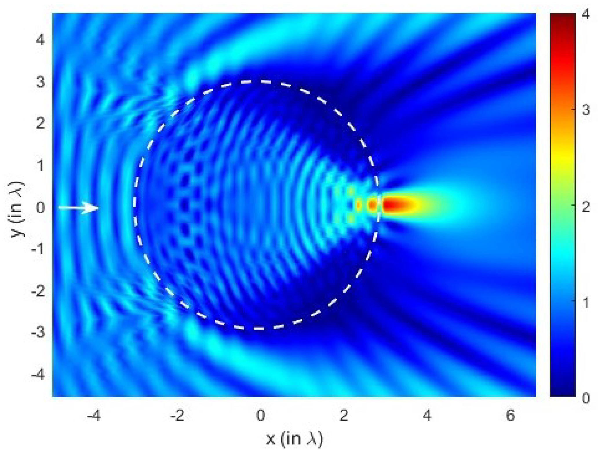
SEM acoustic simulations are performed for varying parameters { R , m } . The structural parameters are adjusted in terms of incident wavelength. While keeping the radius of the particle as well as the index ratio of the system in a specific range, the SEM simulations predict that the subwavelength localization and acoustic jet formation could be achieved, see Figure 1, Figure 2, Figure 3 and Figure 4. As an illustration, the structural parameters are set to be { R , m } = { 3 , 3 } and the corresponding scattering wave distribution is calculated via SEM method, see the two-dimensional (2D) acoustic intensity distribution in Figure 1. The acoustic jet excitation is realized at the shadow of the particle, which can be observed explicitly in the figure; subwavelength localization is generated with a full-width at half maximum value of F W H M = 0.51 λ and the corresponding field enhancement is around I I 0 = 3.7 , which is the indication of the strong field localization in terms of incident wave.
Figure 1 (Color online). The 2D intensity distribution of the Wave scattering on the sphere with diameter: R = 3 and m = 3 . Corresponding FWHM of the generated acoustojet is calculated as 0.51 λ .
Figure 1. (Color online). The 2D intensity distribution of the Wave scattering on the sphere with diameter: R = 3 and m = 3 . White arrow indicates the direction of incident plane wave while the dashed region represents the boundary of the sphere. The corresponding FWHM of the generated acoustojet is calculated as 0.51 λ .
Mathematics 10 03145 g001
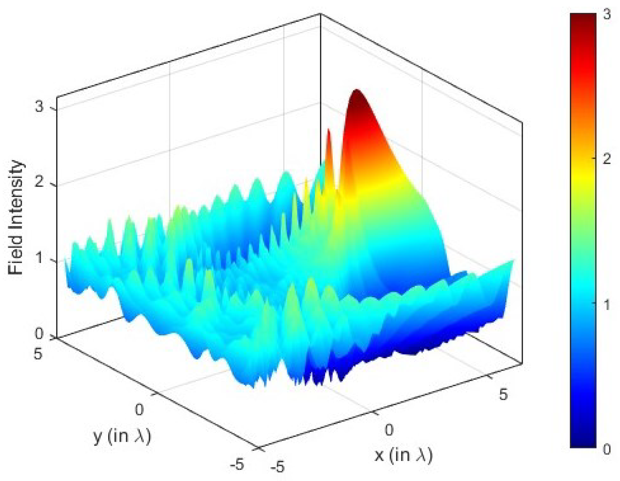
Figure 2. (Color online). Scattering on spheres with diameter: R = 3.5 and m = 2.89 . Corresponding FWHM of the generated acoustojet is calculated as 0.29 λ .
Mathematics 10 03145 g002
Figure 3. (Color online). Scattering on spheres with diameter: R = 3 and m = 2 . Corresponding FWHM of the generated acoustojet is calculated as 0.67 λ .
Mathematics 10 03145 g003
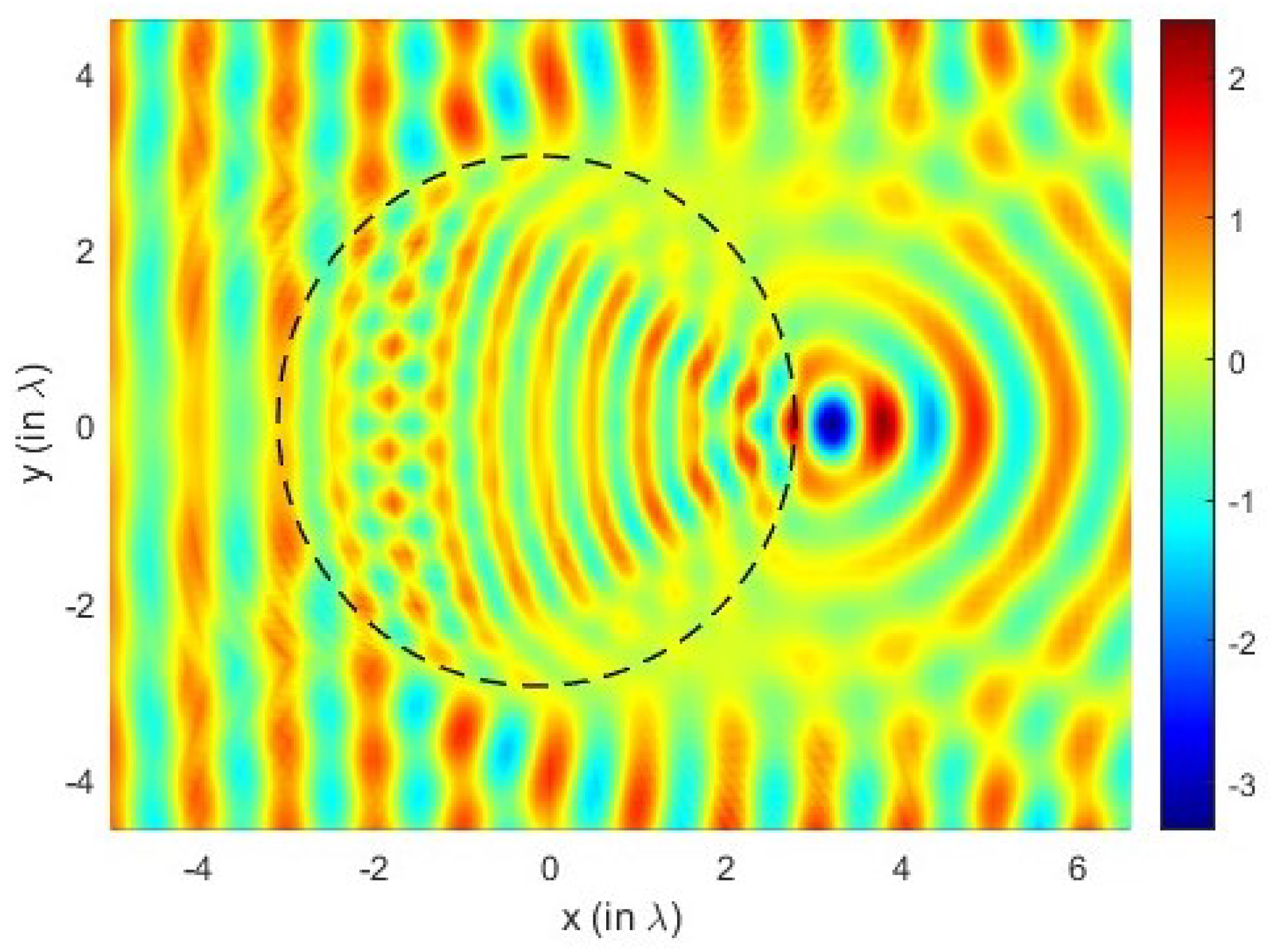
Figure 4. (Color online). Scattering on spheres with diameter: R = 3 and m = 3 .
Mathematics 10 03145 g004
Proper arrangement of structural parameters enhances the field intensity as well as the subwavelength localization capability of the generated acoustic jet. For that purpose, the structural parameters are adjusted to be { R , m } = { 3.5 , 2.89 } and the corresponding field intensity distribution is represented in Figure 2. Stronger subwavelength localization is achieved with F W H M = 0.29 λ and the field enhancement of I I 0 = 10.48 . Another important finding is simultaneous existence of whispering gallery modes (WGMs) with acoustic jet, which has not been reported before in acoustic jet studies. Corresponding radial and angular mode number of existing WGMs equals { n , l } = { 2 , 58 } . While fixing the ratio of the lens as in Figure 1, the index ratio is arranged to be m = 2 . In this case, subwavelength localization is still conserved with F W H M = 0.67 λ and the field enhancement of I I 0 = 3.7 . Comparing both Figure 1 and Figure 3, it can be noted that an increment in the index ratio directly enhances the strength of the wave localization as well as subwavelength focusing capability of the particle. In Figure 4 the real part of the scattered field on a sphere with diameter: R = 3 and m = 3 is shown. The plane wave is incident from the left side and the dashed region represents the boundary of the penetrable particle.
Figure 3 (Color online) has the scattering on spheres with diameter: R = 3 and m = 2 . The corresponding FWHM of the generated acoustojet is calculated as 0.67 λ .
Figure 4 (Color online). Scattering on spheres with diameter: R = 3 and m = 3 . The plane wave is incident from the left side and the dashed region represents the boundary of the penetrable particle.
SEM-simulated acoustic jet phenomenon could also be validated in macroscopic scale via the following experimental setup: A delay line can be placed in front of the ultrasound transducer to provide plane waves excitation toward the spherical lens. Then, the incoming plane wave scatters on the spherical lens and acoustic jet is generated at the shadow-side of the penetrable particle. The produced acoustic jet could be probed by needle microphone that is very close to the sphere for the measurement of the output acoustic field in spatial domain. The detected field could be amplified, band-pass filtered to reduce the received background noise, and visualized by an oscilloscope [6].
As a future aspect, the acoustojet phenomenon could be implemented for subwavelength acoustic lensing [37] and the proposed structure could be modified intentionally to gather acoustic hook or tweezer effect [38].

5. Conclusions

In conclusion, SEM formulation is revised to enable acoustic wave scattering calculations. It has been proved via 2D acoustic simulations that the proper adjustment of structural parameters in acoustic SEM model provides acoustic jet formation. Furthermore, possible experimental setup for the validation of investigated acoustic jet phenomenon is explained in detail. As a novelty of the study, in addition to the provided SEM formulation, resonant propagation modes may occur simultaneously with acoustojets, which has never been reported before in the literature.

Author Contributions

Data curation, I.H.G.; Formal analysis, W.H.F.A.; Investigation, S.A.; Methodology, I.M. and A.Y.; Resources, H.K. All authors have read and agreed to the published version of the manuscript.

Funding

This research received no external funding.

Conflicts of Interest

The authors declare no conflict of interest.

References

  1. Taflove, A.; Backman, V. Photonic nanojet enhancement of backscattering of light by nanoparticles: A potential novel visible-light ultramicroscopy technique. Opt. Express 2004, 12, 1214–1220. [Google Scholar]
  2. Mahariq, I.; Kuzuoğlu, M.; Tarman, I.H.; Kurt, H. Photonic nanojet analysis by spectral element method. IEEE Photonics J. 2014, 6, 6802714. [Google Scholar] [CrossRef]
  3. Eti, N.; Giden, I.; Hayran, Z.; Rezaei, B.; Kurt, H. Manipulation of photonic nanojet using liquid crystals for elliptical and circular core-shell variations. J. Mod. Opt. 2017, 64, 1566–1577. [Google Scholar] [CrossRef]
  4. Mitri, F. Ultrasonic superlensing jets and acoustic-fork sheets. Phys. Lett. A 2017, 381, 1648–1654. [Google Scholar] [CrossRef]
  5. Cummer, S.A.; Christensen, J.; Alù, A. Controlling sound with acoustic metamaterials. Nat. Rev. Mater. 2016, 1, 16001. [Google Scholar] [CrossRef]
  6. Veira Canle, D.; Kekkonen, T.; Mäkinen, J.; Puranen, T.; Nieminen, H.J.; Kuronen, A.; Franssila, S.; Kotiaho, T.; Salmi, A.; Hæggström, E. Practical realization of a sub-λ/2 acoustic jet. Sci. Rep. 2019, 9, 5189. [Google Scholar] [CrossRef]
  7. Zhao, L.; Horiuchi, T.; Yu, M. Broadband ultra-long acoustic jet based on double-foci Luneburg lens. JASA Express Lett. 2021, 1, 114001. [Google Scholar] [CrossRef]
  8. Minin, O.V.; Minin, I.V. Acoustic Hook. In The Photonic Hook: From Optics to Acoustics and Plasmonics; Springer International Publishing: Cham, Switzerland, 2021; pp. 39–53. [Google Scholar] [CrossRef]
  9. Castiñeira-Ibañez, S.; Tarrazó-Serrano, D.; Uris, A.; Rubio, C. Tunable acoustic hooks from Janus cylinder. Results Phys. 2021, 24, 104134. [Google Scholar] [CrossRef]
  10. Littlefield, A.J.; Zhu, J.; Messinger, J.F.; Goddard, L.L. Photonic Nanojets. Opt. Photonics News 2021, 32, 34–41. [Google Scholar] [CrossRef]
  11. Rayleigh, L. CXII. The problem of the whispering gallery. Lond. Edinb. Dublin Philos. Mag. J. Sci. 1910, 20, 1001–1004. [Google Scholar] [CrossRef] [Green Version]
  12. Vahala, K.J. Optical microcavities. Nature 2003, 424, 839–846. [Google Scholar] [CrossRef] [PubMed]
  13. Matsko, A.B. Practical Applications of Microresonators in Optics and Photonics; CRC Press: Boca Raton, FL, USA, 2018. [Google Scholar]
  14. Mahariq, I.; Giden, I.H.; Kurt, H.; Minin, O.V.; Minin, I.V. Strong electromagnetic field localization near the surface of hemicylindrical particles. Opt. Quantum Electron. 2018, 50, 423. [Google Scholar] [CrossRef]
  15. Mahariq, I.; Abdeljawad, T.; Karar, A.S.; Alboon, S.A.; Kurt, H.; Maslov, A.V. Photonic nanojets and whispering gallery modes in smooth and corrugated micro-cylinders under point-source illumination. Photonics 2020, 7, 50. [Google Scholar] [CrossRef]
  16. Mahariq, I.; Kurt, H. Strong field enhancement of resonance modes in dielectric microcylinders. JOSA B 2016, 33, 656–662. [Google Scholar] [CrossRef]
  17. Mednikov, E.; Novitskii, B. Experimental study of intense acoustic streaming. Sov. Phys. Acoust. 1975, 21, 152–154. [Google Scholar]
  18. Lebedeva, I. Experimental study of acoustic streaming in the vicinity of orifices. Sov. Phys. Acoust. 1980, 26, 331–333. [Google Scholar]
  19. Thomas, D.C.; Gee, K.L.; Turley, R.S. A balloon lens: Acoustic scattering from a penetrable sphere. Am. J. Phys. 2009, 77, 197–203. [Google Scholar] [CrossRef]
  20. Lopes, J.; Andrade, M.; Leao-Neto, J.; Adamowski, J.; Minin, I.; Silva, G. Focusing acoustic beams with a ball-shaped lens beyond the diffraction limit. Phys. Rev. Appl. 2017, 8, 024013. [Google Scholar] [CrossRef]
  21. Minin, O.V.; Minin, I.V. Acoustojet: Acoustic analogue of photonic jet phenomenon based on penetrable 3D particle. Opt. Quantum Electron. 2017, 49, 54. [Google Scholar] [CrossRef]
  22. Patera, A.T. A spectral element method for fluid dynamics: Laminar flow in a channel expansion. J. Comput. Phys. 1984, 54, 468–488. [Google Scholar] [CrossRef]
  23. Maday, Y.; Patera, A.T. Spectral element methods for the incompressible Navier-Stokes equations. In State-of-the-Art Surveys on Computational Mechanics (A90-47176 21-64); American Society of Mechanical Engineers: New York, NY, USA, 1989; pp. 71–143. [Google Scholar]
  24. Komatitsch, D.; Tromp, J. Introduction to the spectral element method for three-dimensional seismic wave propagation. Geophys. J. Int. 1999, 139, 806–822. [Google Scholar] [CrossRef]
  25. Deville, M.O.; Fischer, P.F.; Fischer, P.F.; Mund, E. High-Order Methods for Incompressible Fluid Flow; Cambridge University Press: Cambridge, UK, 2002; Volume 9. [Google Scholar]
  26. Lee, J.H.; Xiao, T.; Liu, Q.H. A 3-D spectral-element method using mixed-order curl conforming vector basis functions for electromagnetic fields. IEEE Trans. Microw. Theory Tech. 2006, 54, 437–444. [Google Scholar]
  27. Lee, J.H.; Liu, Q.H. A 3-D spectral-element time-domain method for electromagnetic simulation. IEEE Trans. Microw. Theory Tech. 2007, 55, 983–991. [Google Scholar] [CrossRef]
  28. Lee, J.H.; Chen, J.; Liu, Q.H. A 3-D discontinuous spectral element time-domain method for Maxwell’s equations. IEEE Trans. Antennas Propag. 2009, 57, 2666–2674. [Google Scholar]
  29. Heikkola, E.; Mönkölä, S.; Pennanen, A.; Rossi, T. Controllability method for acoustic scattering with spectral elements. J. Comput. Appl. Math. 2007, 204, 344–355. [Google Scholar] [CrossRef]
  30. Pike, E.R.; Sabatier, P.C. Scattering, Two-Volume Set: Scattering and Inverse Scattering in Pure and Applied Science; Elsevier: Amsterdam, The Netherlands, 2001. [Google Scholar]
  31. Berenger, J.P. A perfectly matched layer for the absorption of electromagnetic waves. J. Comput. Phys. 1994, 114, 185–200. [Google Scholar] [CrossRef]
  32. Sacks, Z.S.; Kingsland, D.M.; Lee, R.; Lee, J.F. A perfectly matched anisotropic absorber for use as an absorbing boundary condition. IEEE Trans. Antennas Propag. 1995, 43, 1460–1463. [Google Scholar] [CrossRef]
  33. Werner, D.H.; Mittra, R. A new field scaling interpretation of Berenger’s PML and its comparison to other PML formulations. Microw. Opt. Technol. Lett. 1997, 16, 103–106. [Google Scholar] [CrossRef]
  34. Qi, Q.; Geers, T.L. Evaluation of the perfectly matched layer for computational acoustics. J. Comput. Phys. 1998, 139, 166–183. [Google Scholar] [CrossRef]
  35. Mahariq, I.; Kuzuoğlu, M.; Tarman, I.H. On the attenuation of the perfectly matched layer in electromagnetic scattering problems with the spectral element method. Appl. Comput. Electromagn. Soc. J. (ACES) 2014, 29, 701–710. [Google Scholar]
  36. Du, Y.; Zhang, J. Perfectly Matched Layers for nonlocal Helmholtz equations II: Multi-dimensional cases. J. Comput. Phys. 2022, 464, 111192. [Google Scholar] [CrossRef]
  37. Zhou, Q.; Xu, Z.; Liu, X. High efficiency acoustic Fresnel lens. J. Phys. D Appl. Phys. 2019, 53, 065302. [Google Scholar] [CrossRef]
  38. Meng, L.; Cai, F.; Li, F.; Zhou, W.; Niu, L.; Zheng, H. Acoustic tweezers. J. Phys. D Appl. Phys. 2019, 52, 273001. [Google Scholar] [CrossRef]
Publisher’s Note: MDPI stays neutral with regard to jurisdictional claims in published maps and institutional affiliations.