Article

Hygrothermal Buckling of Smart Graphene/Piezoelectric Nanocomposite Circular Plates on an Elastic Substrate via DQM

by
Mashhour A. Alazwari
1,
Ashraf M. Zenkour
2,* and
Mohammed Sobhy
3,4
1
Mechanical Engineering Department, Faculty of Engineering, King Abdulaziz University, P.O. Box 80204, Jeddah 21589, Saudi Arabia
2
Department of Mathematics, Faculty of Science, King Abdulaziz University, P.O. Box 80203, Jeddah 21589, Saudi Arabia
3
Department of Mathematics and Statistics, College of Science, King Faisal University, P.O. Box 400, Al-Ahsa 31982, Saudi Arabia
4
Department of Mathematics, Faculty of Science, Kafrelsheikh University, Kafrelsheikh 33516, Egypt
*
Author to whom correspondence should be addressed.
Mathematics 2022, 10(15), 2638; https://doi.org/10.3390/math10152638
Submission received: 25 June 2022 / Revised: 22 July 2022 / Accepted: 25 July 2022 / Published: 27 July 2022

Abstract

:
This paper aims to study the hygrothermal buckling of smart graphene/piezoelectric circular nanoplates lying on an elastic medium and subjected to an external electric field. The circular nanoplates are made of piezoelectric polymer reinforced with graphene platelets that are uniformly distributed through the thickness of the nanoplate. The material properties of the nanocomposite plate are determined based on the modified Halpin-Tsai model. To capture the nanoscale effects, the nonlocal strain gradient theory is applied. Moreover, the principle of virtual work is employed to establish the nonlinear stability equations in the framework of classical theory. The differential quadrature method is utilized to solve the governing equations. Among the important aims of the paper is to study the influences of various parameters such as graphene weight fraction, elastic foundation parameters, external applied electric field, humid conditions, and boundary conditions on the thermal buckling of the smart nanocomposite circular nanoplates. It is found that the increase in graphene components and elastic foundation stiffness enhances the strength of the plates; therefore, the buckling temperature will increase.

1. Introduction

Many real-life applications, such as transducers, pressure sensors, actuators [1], ultrasonic [2,3,4], medical [5,6], and automobile structures [7,8], use piezoelectric materials due to their distinct characteristics and unique electrical, mechanical, chemical, and thermal properties. The piezoelectric materials possess two important phenomena: direct piezoelectric effect, in which the mechanical energy is converted to electrical energy, and converse piezoelectric effect, where the electrical energy is converted to mechanical energy [9]. Thus, due to the aforementioned characteristics, many studies have been implemented on the behavior of piezoelectric materials [10,11,12,13,14,15,16]. Sun [1] employed Reddy’s higher-order shear deformation theory to study the buckling analysis of piezoelectric fiber-reinforced cylindrical shells exposed to mechanical load, thermal load, and electric voltage. Based on a quasi-3D refined theory, Zenkour and Aljadani [17] analyzed the buckling of functionally graded piezoelectric plates exposed to mechanical load and electric voltage. On the other hand, Zenkour and Alghanmi [18] illustrated the bending of functionally graded piezoelectric sandwich plates exposed to thermos-electro-mechanical loads and rested on an elastic substrate utilizing four-unknown shear deformation theory. Moreover, the improvement of the performance of piezoelectric materials has received much attention from many researchers. The superior mechanical properties, high thermal conductivity, and high flexibility of graphene make graphene reinforcement one of the favorable techniques for improving the performance of piezoelectric materials [19,20,21,22].
Graphene reinforcements, where a two-dimensional thick layer of carbon is used, have been applied in many systems due to their extraordinary mechanical, thermal, and electrical properties. Graphene nanoplatelets (GPLs), which are one of the derivatives of graphene, have been widely used as reinforcing nanofillers in graphene-based polymer nanocomposite materials for their ability to improve the performance of these materials. It is reported that the use of 0.1 wt% GPLs in polymeric nanocomposites caused Young’s modulus and the tensile strength to be increased by 31% and 40%, respectively [23]. Due to these facts, many studies have been implemented to study the behavior of these materials in terms of vibration, buckling, and static responses. The magneto-electro-thermal bending and the free vibration analysis of functionally graded composite doubly curved shallow shells reinforced with GPLs were studied by Sobhy and Zenkour [24,25]. Arefi et al. [26] studied the effect of GPLs on the thermal buckling response of functionally graded materials based on the modified couple stress theory. Thai et al. [27] used the NURBS formulation for the free vibration, buckling and bending analyses of functionally graded plates reinforced with GPLs. The natural frequency of functionally graded plates reinforced with GPLs under different boundary conditions was investigated by Sobhy and Zenkour [25] using a four-variable shear deformation shell theory. Based on the nonlocal strain gradient theory, the size-dependent effects on the wave propagation in functionally graded GPLs-reinforced bi-layer nanobeams were studied by Zenkour and Sobhy [28]. In that study, the bi-layer nanocomposite beams are exposed to an axial magnetic field as well as in-plane compressive load and embedded in an elastic medium. While, in Sobhy [29], 3-D axisymmetric and asymmetric deformation of circular plates reinforced with GPLs and lying on an elastic substrate were investigated. Mao et al. [30] investigated the linear and nonlinear vibrations functionally gradient piezoelectric composite microplate which is reinforced with graphene nanoplatelet. Kundalwal et al. [31] studied the electromechanical response of graphene reinforced nanocomposite using exact solutions and finite element models. Buckling and post-buckling analyses of dielectric composite beams reinforced with GPLs were illustrated by Wang [32] employing the differential quadrature method; whereas Wang [33] utilized the first-order shear deformation plate theory to demonstrate the nonlinear bending of dielectric composite plates reinforced with functionally graded GPLs. Wu et al. [34] investigated the large amplitude vibration of FG-GPLs reinforced annular plates in thermal environments based on the first-order shear deformation theory and von Karman nonlinear theory. Zhao et al. [35] presented a brief review of the mechanical properties of graphene nanocomposites and a comprehensive review of the mechanical analyses of FG-GPLs reinforced structures.
As viewed in the above survey, some recent works have been introduced in the open literature studying the behavior of GPLs-reinforced piezoelectric rectangular plates [30,33] and beams [31,32] neglecting the graphene/piezoelectric circular plates. Moreover, the hygrothermal effects on such structures are not considered in the literature. Therefore, the current study will first attempt to analyze the hygrothermal buckling of piezoelectric circular plates reinforced with graphene platelets. In addition, the nanoscale effects are considered by employing the nonlocal strain gradient theory. The smart circular nanoplate is lying on an elastic medium and subjected to the electric field, humid conditions, and elevated temperature. In the framework of the modified Halpin-Tsai model, the material properties of the nanocomposite plate are estimated. The stability equations are deduced from the principle of virtual work. These equations are solved numerically based on the differential quadrature method. The impacts of several parameters on the thermal buckling of the smart nanocomposite circular nanoplates are presented and discussed in detail.

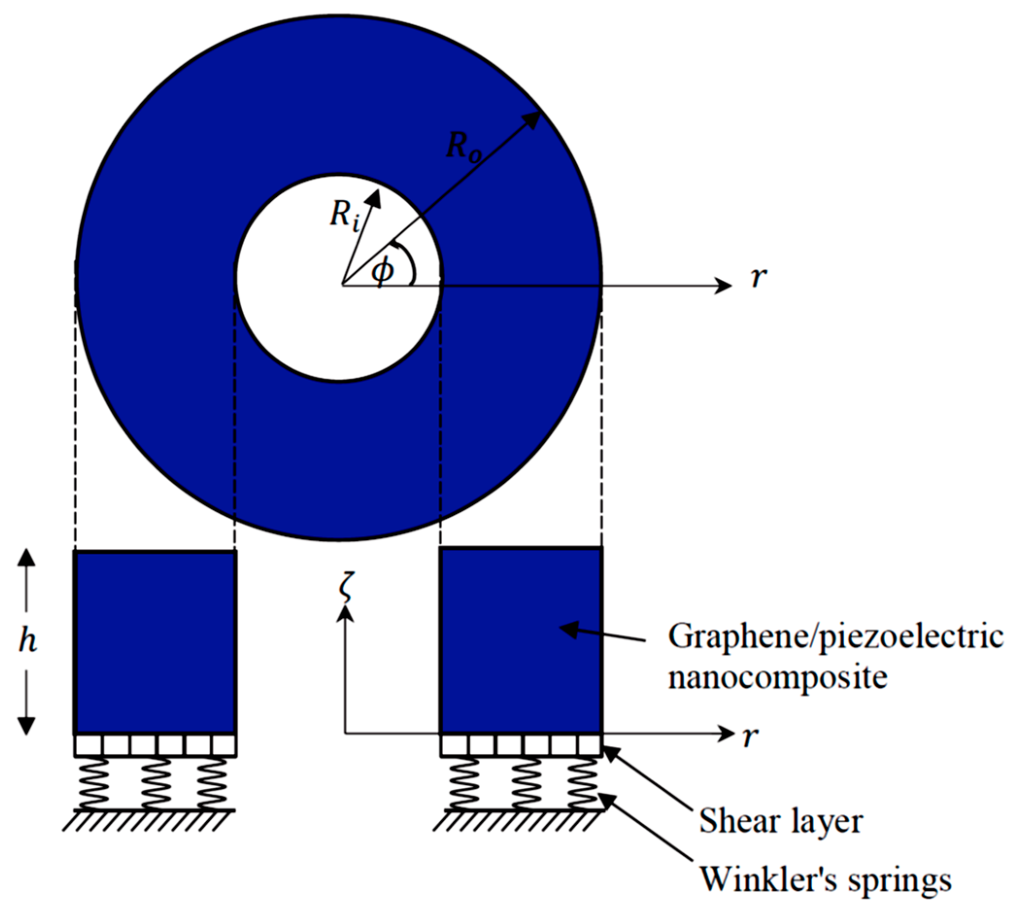
2. Nanoplate Configuration

Consider a circular flat nanoplate composed of a mixture of piezoelectric polymer (Polyvinylidene Fluoride) and graphene platelets (GPLs). The piezoelectric constituent of the structure represents a matrix, and the GPLs stand for the reinforced constituents. The GPLs are uniformly distributed through the thickness of the nanoplate. For an annular plate, the inner radius and outer one are R i and R o , respectively, while the plate thickness is h as shown in Figure 1. Polar coordinates ( r , ϕ , ζ ) are considered in the present analysis. The graphene volume fraction V g is expressed in terms of the weight fraction of graphene w g , and densities of graphene ρ g and piezoelectric polymer ρ p as [36]:
V g = w g ρ p w g ρ p + ρ g ( 1 w g ) .
The effective Young’s modulus of the nanocomposite plate can be calculated following the modified Halpin-Tsai model [37,38] as:
E c = 3 8 E L + 5 8 E T ,
where E L and E T are the longitudinal modulus and transverse modulus, respectively, that can be given as [37,38]:
E L = 1 + ξ a η 1 g V g 1 ξ a V g E p ,           E T = 1 + ξ b η 2 g V g 1 ξ b V g E p ,
where E p is Young’s modulus of the piezoelectric polymer, ξ a and ξ b are given as [38]:
ξ a = E g E p E g + η 1 g E p ,           ξ b = E g E p E g + η 2 g E p , η 1 g = 2 A g H g ,           η 2 g = 2 B g H g ,
where E g represents Young’s modulus of the GPLs, A g , B g and H g are, respectively, the length, width, and thickness of GPLs. In addition, Poisson’s ratio ν c , moisture expansion coefficient β c , thermal expansion coefficient α c , piezoelectric constants ϵ i k c and dielectric constants λ k c of the nanocomposite plate are given according to the rule of mixture [38] as:
ν c = V g ν g + V p ν p , β c = V g β g + V p β p , α c = V g α g + V p α p , ϵ i k c = V g ϵ i k g + V p ϵ i k p , λ k c = V g λ k g + V p λ k p , V p = 1 V g ,
where ν g ( ν p ) , β g ( β p ) , α g ( α p ) , ϵ i k g ( ϵ i k p ) and λ k g ( λ k p ) are Poisson’s ratio, moisture expansion coefficients, thermal expansion coefficients, piezoelectric constants, and dielectric constants of the GPLs (piezoelectric polymer), respectively.

3. Constitutive Equations

The nonlinear strain-displacement relations are introduced as [39]:
ε r r = 𝒰 , r + 1 2 ( 𝒲 , r ) 2 ,           ε ϕ ϕ = 1 r 𝒱 , ϕ + 𝒰 r + 1 2 ( 1 r 𝒲 , ϕ ) 2 , ε r ϕ = 1 r 𝒰 , ϕ + 𝒱 , r 𝒱 r + 1 r 𝒲 , r 𝒲 , ϕ , ε r ζ = 𝒰 , ζ + 𝒲 , r + 𝒲 , r 𝒲 , ζ ,             ε ϕ ζ = 𝒱 , ζ + 1 r 𝒲 , ϕ + 1 r 𝒲 , ϕ 𝒲 , ζ ,
where 𝒰 , 𝒱 , and 𝒲 indicate the components of the displacement field in the r , ϕ , and ζ directions, respectively, and X , s = X / s .
Following the classical plate theory, the displacement field is expressed as:
{ 𝒰 ( r , ϕ , ζ ) 𝒱 ( r , ϕ , ζ ) 𝒲 ( r , ϕ , ζ ) } = { u ( r , ϕ ) v ( r , ϕ ) w ( r , ϕ ) } ζ { w , r 1 r w , ϕ 0 } .
Inserting Equation (7) into the general strain relations (6) leads to the kinematic equations as:
{ ε r r ε ϕ ϕ ε r ϕ } = { ε r r ( 0 ) ε ϕ ϕ ( 0 ) ε r ϕ ( 0 ) } + ζ { ε r r ( 1 ) ε ϕ ϕ ( 1 ) ε r ϕ ( 1 ) } ,           ε ζ ζ = ε r ζ = ε ϕ ζ = 0 ,
where:
{ ε r r ( 0 ) ε ϕ ϕ ( 0 ) ε r ϕ ( 0 ) } = { u , r + 1 2 w , r 2 1 r v , ϕ + 1 r u + 1 2 r 2 w , ϕ 2 1 r u , ϕ + v , r 1 r v + 1 r w , r w , ϕ } ,           { ε r r ( 1 ) ε ϕ ϕ ( 1 ) ε r ϕ ( 1 ) } = { w , r r 1 r 2 w , ϕ ϕ + 1 r w , r 2 r w , r ϕ 2 r 2 w , ϕ } .
In the framework of the piezoelasticity theory [40] and the nonlocal strain gradient theory [41], the constitutive equations considering the hygrothermal effects can be given as:
Λ L σ i j = Λ S ( 𝒬 i j k l ε k l ϵ i j k E ¯ k α ¯ i j T β ¯ i j C ) , Λ L D j = Λ S ( ϵ j k l ε k l λ j k E ¯ k + p j T + q j C ) ,
where 𝒬 i j k l are the elastic constants, ϵ i j k are piezoelectric constants, λ j k are dielectric constants, α ¯ i j are thermal moduli, β ¯ i j are moisture moduli, ( p j , q j ) are pyroelectric constants and T and C are the applied temperature and moisture, respectively. While Λ L and Λ S are, respectively, the nonlocal and strain gradient operators, which are expressed as [41]:
Λ L = 1 μ 2 2 ,           Λ S = 1 γ 2 2 ,           2 = 2 r 2 + 1 r r + 1 r 2 2 ϕ 2 ,
where μ is the nonlocal coefficient and γ is the strain gradient coefficient. For isotropic plate, the nonlocal constitutive relations and electric displacement D k (Equation (10)) can be expressed as:
Λ L { σ r r σ ϕ ϕ σ r ϕ } = Λ S [ 𝒬 11 𝒬 12 0 𝒬 12 𝒬 22 0 0 0 𝒬 66 ] c { ε r r α c T β c C ε ϕ ϕ α c T β c C ε r ϕ } Λ S [ 0 0 ϵ 13 0 0 ϵ 13 0 0 0 ] c { E ¯ r E ¯ ϕ E ¯ ζ } ,
and:
Λ L { D r D ϕ D ζ } = Λ S [ 0 0 0 0 ϵ 15 0 0 0 ϵ 15 0 ϵ 13 ϵ 13 0 0 0 ] c { ε r r α j T β j C ε ϕ ϕ α j T β j C ε r ϕ ε ϕ ζ ε r ζ } + Λ S [ λ 1 0 0 0 λ 1 0 0 0 λ 3 ] c { E ¯ r E ¯ ϕ E ¯ ζ } ,
where the stiffness coefficients are given as:
𝒬 11 c = 𝒬 22 c = E c 1 ν c 2 ,             𝒬 12 c = ν c E c 1 ν c 2 ,           𝒬 66 c = E c 2 ( 1 + ν c ) ,
and E ¯ k ( k = r , ϕ , ζ ) are the electric field. It is assumed that the actuator is poled along the ζ direction. So, the applied electric field vector can be given as [42]:
E ¯ = ( 0 , 0 , E ζ h ) .

4. Stability Equations

For the circular plate resting on an elastic substrate and subjected to hygrothermal loads and external voltage, the principle of virtual work is defined as:
δ Υ S δ Υ F = 0 ,
where δ Υ S is the variation of the strain energy and δ Υ F is a variation of the work done by the elastic substrate. It reads:
δ Υ S = R i R o 0 2 π h / 2 h / 2 ( σ k l δ ε k l D k δ E k ) r d ζ d ϕ d r ,           k , l = r , ϕ , ζ ,
Inserting Equation (8) into Equation (17) gives the variation δ Υ S as:
δ Υ S = R i R o 0 2 π ( N r r δ ε r r ( 0 ) + M r r δ ε r r ( 1 ) + N ϕ ϕ δ ε ϕ ϕ ( 0 ) + M ϕ ϕ δ ε ϕ ϕ ( 1 ) + N r ϕ δ ε r ϕ ( 0 ) + M r ϕ δ ε r ϕ ( 1 ) ) r d ϕ d r ,
where:
{ N k l , M k l } = h 2 h 2 σ k l { 1 , ζ } d ζ ,           k ,   l = r , ϕ .
However, the variation of the work performed by the elastic substrate δ Υ F is defined as:
δ Υ F = R i R o 0 2 π Γ δ w r d ϕ d r ,
where Γ represents the elastic foundation reaction, which can be expressed as:
Γ = J w w J p ( 2 w r 2 + 1 r w r + 1 r 2 2 w ϕ 2 ) ,
where J w and J p are Winkler and Pasternak coefficients, respectively.
By incorporating Equations (18) and (20) into Equation (16) with the help of Equation (9), one can obtain the stability equations as follows:
N r r , r + 1 r ( N r ϕ , ϕ + N r r N ϕ ϕ ) = 0 , N r ϕ , r + 1 r ( 2 N r ϕ + N ϕ ϕ , ϕ ) = 0 , M r r , r r + 2 r M r r , r + 1 r 2 M ϕ ϕ , ϕ ϕ 1 r M ϕ ϕ , r + 2 r M r ϕ , r ϕ + 2 r 2 M r ϕ , ϕ + 1 r ( r N r r w , r ) , r + 1 r 2 ( N ϕ ϕ w , ϕ ) , ϕ + 1 r ( N r ϕ w , ϕ ) , r + 1 r ( N r ϕ w , r ) , ϕ J w w + J p 2 w = 0 .
The force and moment resultants N k l and M k l   ( k , l = r , ϕ ) are calculated by:
N r r M r r N ϕ ϕ M ϕ ϕ = O 11 O 12 L 11 L 12 O 12 O 22 L 12 L 22 L 11 L 12 O 11 O 12 L 12 L 22 O 12 O 22 ε r r ( 0 ) ε r r ( 1 ) ε ϕ ϕ ( 0 ) ε ϕ ϕ ( 1 ) + N r r T M r r T N ϕ ϕ T M ϕ ϕ T + N r r C M r r C N ϕ ϕ C M ϕ ϕ C + N r r E M r r E N ϕ ϕ E M ϕ ϕ E , { N r ϕ M r ϕ } = [ O ¯ 11 O ¯ 12 O ¯ 12 O ¯ 22 ] { ε r ϕ ( 0 ) ε r ϕ ( 1 ) } ,
where:
{ O 11 , O 12 , O 22 } = h / 2 h / 2 𝒬 11 c { 1 , ζ , ζ 2 } d ζ , { L 11 , L 12 , L 22 } = h / 2 h / 2 𝒬 12 c { 1 , ζ , ζ 2 } d ζ , { O ¯ 11 , O ¯ 12 , O ¯ 22 } = h 2 h 2 𝒬 66 c { 1 , ζ , ζ 2 } d ζ , { N r r T , M r r T } = { N ϕ ϕ T , M ϕ ϕ T } = h / 2 h / 2 α c E c 1 ν c T { 1 , ζ } d ζ , { N r r C , M r r C } = { N ϕ ϕ C , M ϕ ϕ C } = h 2 h 2 β c E c 1 ν c C { 1 , ζ } d ζ , { N r r E , M r r E } = { N ϕ ϕ E , M ϕ ϕ E } = h 2 h 2 ϵ 13 c E ζ h { 1 , ζ } d ζ .
In accordance with the virtual displacement concept [39,43,44,45,46], the displacement components of the circular nanocomposite plate are defined as:
u = u 0 + u 1 ,           v = v 0 + v 1 ,           w = w 0 + w 1 ,
where ( u 0 , v 0 , w 0 ) denote the displacements of the equilibrium state, ( u 1 , v 1 , w 1 ) denote the virtual displacement components of a neighboring stable state. In addition, the force and moment resultants associated with the virtual displacement of the neighboring stable state are also written as N k l 1 , M k l 1 . Based on the concept of virtual displacement and for the asymmetric circular plates, the equilibrium Equation (22) tend to the following linear stability equations:
N r r , r 1 + 1 r ( N r ϕ , ϕ 1 + N r r 1 N ϕ ϕ 1 ) = 0 ,           N r ϕ , r 1 + 1 r ( 2 N r ϕ 1 + N ϕ ϕ , ϕ 1 ) = 0 ,           M r r , r r 1 + 2 r M r r , r 1 + 1 r 2 M ϕ ϕ , ϕ ϕ 1 1 r M ϕ ϕ , r 1 + 2 r M r ϕ , r ϕ 1 + 2 r 2 M r ϕ , ϕ 1 + ( N r r 0 + J p ) 2 w 1 J w w 1 = 0 .
where N r r 0 = N r r T + N r r C + N r r E . The temperature field T and humid concentration C are derived from the heat conduction equation and moisture diffusion equation with the aid of the boundary conditions. They read:
d d ζ [ ϖ d Υ ( ζ ) d ζ ] = 0 ,           Υ = T , C , T ( h 2 ) = T 0 ,           T ( h 2 ) = T t ,           C ( h 2 ) = C 0 ,         C ( h 2 ) = C t ,
where ϖ represents the thermal conductivity and humid diffusivity, T 0 and C 0 are, respectively, the temperature and moisture of the bottom surface, T t and C t are, respectively, the temperature and moisture of the top surface. By solving Equation (27), one obtains the temperature and moisture as:
T ( ζ ) = Δ T 1 2 + ζ h + T 0 , Δ T = T t T 0 , C ( ζ ) = Δ C 1 2 + ζ h + C 0 , Δ C = C t C 0 .
By substituting Equation (28) into Equation (24), the hygro-thermo-electric force N r r 0 can be deduced as:
N r r 0 = α c E c 1 ν c h ( 1 2 Δ T + T 0 ) β c E c 1 ν c h ( 1 2 Δ C + C 0 ) + ϵ 13 c E ζ .
To consider the small-scale effects, we apply the nonlocal operator Δ L to the stability Equation (26) and then substitute Equation (23) into the resulting equations with the aid of Equations (9) and (12). Therefore, we get
1 γ 2 2 O 11 u , r r 1 + 1 r u , r 1 1 r 2 u 1 1 r 2 v , ϕ 1 + L 11 1 r v , r ϕ 1 + O 12 w , r r r 1 1 r w , r r 1 + 1 r 2 w , r 1 + 1 r 3 w , ϕ ϕ 1 + L 12 1 r 2 w , r ϕ ϕ 1 + 1 r 3 w , ϕ ϕ 1 + O ¯ 11 1 r v , r ϕ 1 1 r 2 v , ϕ 1 + 1 r 2 u , ϕ ϕ 1 + O ¯ 12 2 r 2 w , r ϕ ϕ 1 + 2 r 3 w , ϕ ϕ 1 = 0 ,
( 1 γ 2 2 ) [ O 11 ( 1 r 2 u , ϕ 1 + 1 r 2 v , ϕ ϕ 1 ) L 11 ( 1 r u , r ϕ 1 ) + O 12 ( 1 r 2 w , r ϕ 1 1 r 3 w , ϕ ϕ ϕ 1 ) + L 12 ( 1 r w , r r ϕ 1 ) + O ¯ 11 ( v , r r 1 + 1 r u , r ϕ 1 + 1 r v , r 1 + 1 r 2 u , ϕ 1 1 r 4 v 1 ) + O ¯ 12 ( 2 r   w , r r ϕ 1 ) ] = 0 ,
1 γ 2 2 O 12 u , r r r 1 + 2 r u , r r 1 1 r 2 u , r 1 1 r 2 v , r ϕ 1 + 1 r 3 u 1 + 1 r 3 v , ϕ 1 + 1 r 3 u , ϕ ϕ 1 + 1 r 3 v , ϕ ϕ ϕ 1 + L 12 1 r v , r r ϕ 1 + 1 r 2 u , r ϕ ϕ 1 + O 22 w , r r r r 1 2 r w , r r r 1 + 1 r 2 w , r r 1 1 r 3 w , r 1 2 r 4 w , ϕ ϕ 1 1 r 4 w , ϕ ϕ ϕ ϕ 1 + L 22 2 r 2 w , r r ϕ ϕ 1 + 2 r 3 w , r ϕ ϕ 1 2 r 4 w , ϕ ϕ 1 + O ¯ 12 2 r v , r r ϕ 1 + 2 r 2 u , r ϕ ϕ 1 + O ¯ 22 4 r 2 w , r r ϕ ϕ 1 + 4 r 3 w , r ϕ ϕ 1 4 r 4 w , ϕ ϕ 1 + 1 μ 2 2 ( N r r 0 + J p ) w , r r 1 + 1 r w , r 1 + 1 r 2 w , ϕ ϕ 1 J w w 1 = 0
Depending on the ensuing notations:
L i j = ν c O i j ,           O ¯ i j = 1 ν c 2 O i j ,         i , j = 1 , 2 ,
one can obtain an uncoupled equation in terms of the displacement w 1 according to the following steps:
  • Differentiate Equation (30) with respect to r ;
  • Multiply Equation (30) by 1 / r ;
  • Differentiate Equation (31) with respect to ϕ and then multiply by 1 / r ;
  • Add the obtained equations in the three above steps;
  • Multiply the obtained equation in step (4) by ( O 12 / O 11 ) and then add to Equation (32).
The uncoupled stability equation is obtained as:
O 11 O 22 O 12 2 O 11 w , r r r r r r 1 + 3 r w , r r r r r 1 2 v c + 1 r 2 w , r r r r 1 + 3 r 2 w , r r r r ϕ ϕ 1 + 4 v c + 2 r 3 w , r r r 1 6 r 3 w , r r r ϕ ϕ 1 + 3 r 4 w , r r ϕ ϕ ϕ ϕ 1 + 4 v c + 17 r 4 w , r r ϕ ϕ 1 6 v c + 3 r 4 w , r r 1 9 r 5 w , r ϕ ϕ ϕ ϕ 1 12 v c + 33 r 5 w , r ϕ ϕ 1 + 6 v c + 3 r 5 w , r 1 + 6 v c + 14 r 6 w , ϕ ϕ ϕ ϕ 1 + 24 v c + 40 r 6 w , ϕ ϕ 1 + 1 r 6 w , ϕ ϕ ϕ ϕ ϕ ϕ 1 γ 2 w , r r r r 1 2 r w , r r r 1 + 1 r 2 w , r r 1 2 r 2 w , r r ϕ ϕ 1 1 r 3 w , r 1 + 2 r 3 w , r ϕ ϕ 1 4 r 4 w , ϕ ϕ 1 1 r 4 w , ϕ ϕ ϕ ϕ 1 + N r r 0 + J p w , r r r r 1 2 r w , r r r 1 2 r 2 w , r r ϕ ϕ 1 + 1 r 2 w , r r 1 + 2 r 3 w , r ϕ ϕ 1 1 r 3 w , r 1 1 r 4 w , ϕ ϕ ϕ ϕ 1 4 r 4 w , ϕ ϕ 1 μ 2 + w , r r 1 + 1 r w , r 1 + 1 r 2 w , ϕ ϕ 1 + J w w , r r 1 + 1 r w , r 1 + 1 r 2 w , ϕ ϕ 1 μ 2 w 1 = 0 .
For asymmetric plate, the lateral displacement w 1 can be presented as [47]:
w 1 ( r , ϕ ) = W ( r ) cos ( κ ϕ ) ,
where κ is the number of nodal diameters. Note that, for κ = 0 , we obtain the axisymmetric buckling of circular nanoplates. While κ > 0 indicates an asymmetric case. Inserting Equation (35) into Equation (34) gives the stability equation as:
c 11 W , r r r r r r + c 21 r   W , r r r r r + ( c 31 r 2 + c 32 ) W , r r r r + ( c 41 r 3 + c 42 r ) W , r r r + ( c 51 r 4 + c 52 r 2 + c 53 ) W , r r + ( c 61 r 5 + c 62 r 3 + c 63 r ) W , r + ( c 71 r 6 + c 72 r 4 + c 73 r 2 + c 74 ) W = 0 ,
where:
c 11 = γ 2 𝒢 , c 21 = 3 γ 2 𝒢 , c 31 = 3 κ 2 + 2 v c + 1 γ 2 𝒢 , c 32 = N r r 0 + J p μ 2 𝒢 , c 41 = 2 c 31 , c 42 = 2 c 32 , c 51 = 3 κ 4 4 v c + 17 κ 2 3 2 v c + 1 γ 2 𝒢 , c 52 = 2 κ 2 + 1 N r r 0 + J p μ 2 + 𝒢 , c 53 = N r r 0 + J p + J w μ 2 , c 61 = 9 κ 4 3 4 v c + 11 κ 2 3 2 v c + 1 γ 2 𝒢 , c 62 = c 52 , c 63 = c 53 , c 71 = κ 4 2 3 v c + 7 κ 2 + 8 3 v c + 5 κ 2 γ 2 𝒢 , c 72 = κ 2 κ 2 4 N r r 0 + J p μ 2 + 𝒢 , c 73 = κ 2 c 53 , c 74 = J w , 𝒢 = o 11 o 22 O 12 2 o 11 .

5. Solution Procedure

In this section, we will employ the differential quadrature method (DQM) [48] to solve the stability Equation (36). The DQM is a common numerical method that has been employed to solve the initial and boundary value problems by many authors (see, e.g., [49,50]). The DQM predicts very accurate results using a considerably smaller number of grid points by comparing with the conventional low-order finite difference and FEM [48]. According to the DQM, the nanocomposite circular plate is discretized in the domain ( R i r R o ) by M mesh points. According to the Gauss-Chebyshev-Lobatto technique, the distributed grid points are expressed as follows:
r k = R o R i 2 [ 1 cos ( k 1 M 1 π ) ] + R i .
The i th derivatives of the displacement with respect to r are approximated as a weighted linear sum of function values at all of the discrete points as follows
d i w r j d r i = k = 1 M G j k ( i ) W r k = k = 1 M G j k ( i ) W k , j = 1 , 2 , 3 , , M ,
where G j k i represent the weighting coefficients for the i th derivative. For the first derivative, it is given as [48]:
G j k ( 1 ) = Ξ ( r j ) ( r j r k ) Ξ ( r k ) ,         j , k = 1 , 2 , 3 , , M ;   j k , G k k ( i ) = = 1 M G j k ( 1 ) ,         k = 1 , 2 , 3 , , M ;   k , Ξ ( r k ) = = 1 M ( r k r ) ,         k ,
while the weighting coefficients for the higher-order derivatives G j k i are estimated by:
G j k ( i ) = = 1 M G j ( 1 ) G k ( i 1 ) , j , k = 1 , 2 , 3 , , M .
In accordance with the DQM, the discretization form of the stability Equation (36) can be obtained as:
c 11 k = 1 M G j k ( 6 ) W k + c 21 r j k = 1 M G j k ( 5 ) W k + c 31 r j 2 + c 32 k = 1 M G j k ( 4 ) W k + c 41 r j 3 + c 42 r j k = 1 M G j k ( 3 ) W k + c 51 r j 4 + c 52 r j 2 + c 53 k = 1 M G j k ( 2 ) W k + c 61 r j 5 + c 62 r j 3 + c 63 r j k = 1 M G j k ( 1 ) W k + c 71 r j 6 + c 72 r j 4 + c c 3 r j 2 + c 74 W j = 0
Moreover, the boundary conditions are defined as:
Simply supported (S):
For r = R i , R o :
k = 1 M G 1 k 2 W k = 0 ,           k = 1 M G M k 2 W k = 0 .
Clamped (C):
For r = R i , R o :
W 1 = W M = 0 .
The conditions at the central point of a solid circular nanoplate can be defined as:
k = 1 M G 1 k 1 W k = 0 .
The stability Equation (42) can be written in the following eigenvalue system:
( [ B ] j Δ T [ B ^ ] j ) { W j } = { 0 } ,
where [ B ] and [ B ^ ] are the stiffness and geometrical matrices. By solving the above eigenvalue problem that appeared in Equation (46) with the help of the boundary conditions (43)–(45), the critical temperature change, which represents the lowest eigenvalue, is obtained using codes written in Maple software.

6. Numerical Results

In this section, the numerical results are introduced to illustrate the influences of different parameters on the critical buckling temperature Δ T c r = R o α p Δ T / D p , D p = h 3 E p / [ 12 ( 1 ν p 2 ) ] of annular and solid smart graphene/piezoelectric (SGP) with simply supported and clamped boundary conditions. The present model is assumed to be exposed to an elevated temperature and humid environments and resting on an elastic substrate with two coefficients (J1, J2), where ( J 1 = J w R o 4 / D p , J 2 = J p R o 2 / D p ). The thickness of the nanocomposite circular plate is taken as h = 100 nm. The properties of the piezoelectric matrix are given as [51]: Ep = 1.4 Gpa, vp = 0.29, ρ p = 1920 kg/m3, ϵ 13 p = 50.535 × 10 3 , ϵ 15 p = 15.93 × 10 3 , λ 1 p = 0.5385 × 10 9 , λ 3 p = 0.59571 × 10 9 , α p = 60 × 10 6 K, β p = 0.44   ( wt . %   H 2 O ) 1 . While the graphene properties are given as [51]: Eg = 1.01 Tpa, ρ g = 800   kg / m 3 , ν g = 0.186 , ϵ 13 g = e 0 ϵ 13 p , ϵ 15 g = e 0 ϵ 15 p , λ 1 g = e 0 λ 1 p , λ 3 g = e 0 λ 3 p , α g = 5 × 10 6 K , β g = 0.26 × 10 3   ( wt . %   H 2 O ) 1 where e 0 is called the piezoelectric multiple [51]. The dimensions of the graphene platelets are given as: Ag = 2.5 nm, B g = 1.5 nm, H g = 1.5 nm. The number of grid points is taken as M = 6 .
In order to demonstrate the validity and accuracy of the present results, the critical buckling temperature of clamped isotropic homogeneous annular plates for different values of the inner radius to outer radius ratio R i / R o and thickness to outer radius ratio h / R o are compared with that depicted by Kiani and Eslami [52] as shown in Table 1. It is noted that the present results have a great agreement with those reported in the literature.
The convergence of the differential quadrature method (DQM) is checked in Figure 2. Obviously, as shown in this figure, the results, with different values of mesh points and outer radius to thickness R o / h of nanocomposite circular plate, show a successful convergence.
It is observed that, as shown in Table 2, the critical buckling temperature Δ T c r for annular circular SGP plates with simply supported boundary conditions increases with increasing the Winkler coefficient J 1 and the Pasternak coefficient J 2 and decreasing the moisture concentration Δ C . A similar trend is observed for solid circular SGP plates where the critical buckling temperature increases with increasing the Winkler coefficient and the Pasternak coefficient and decreasing the moisture concentration. However, it is noticed that the trend is less steep in the case of solid SGP plates compared to the trend observed in annular SGP plates as the Winkler coefficient increases. The influences of the graphene weight fraction w g , electric field E ζ and moisture concentration Δ C on the critical buckling temperature Δ T c r are shown in Table 3 in which the results show, for annular and solid SGP plates, that a successive increase in the critical buckling temperature Δ T c r as the electric field E ζ increases and the moisture concentration Δ C decreases. However, it is observed that increasing the weight fraction w g leads to a decrease in the critical buckling temperature Δ T c r .
Figure 3, Figure 4, Figure 5 and Figure 6 illustrate the effect of outer radius to thickness ratio R o / h along with the effect of the graphene weight fraction w g , number of nodal diameter κ , moisture concentration Δ C , piezoelectric multiple e 0 , Winkler coefficient J 1 . It is observed that the critical buckling temperatures Δ T c r monotonically increase as the outer radius to thickness ratio R o / h increases. Additionally, it is noticed that for the same value of the outer radius to thickness ratio R o / h , the critical buckling temperature Δ T c r increases with increasing each of the graphene weight fraction wg (see Figure 3), number of nodal diameter κ (see Figure 4), Winkler coefficient J 1 (see Figure 6). However, as shown in Figure 5a, increasing the moisture concentration Δ C leads to a noticeable drop in the critical buckling temperature when the piezoelectric multiple e 0 = 10 , while the drop in the critical buckling temperature Δ T c r becomes small when e 0 = 100 (Figure 5b).
Now, the effect of the outer radius to thickness ratio R o / h and inner radius to outer radius ratio R i / R o in conjunction with the effect of the Pasternak coefficient J 2 and the electric field E ζ for simply supported and clamped boundary conditions are shown in Figure 7 and Figure 8. For the case of simply supported SGP annular plates, Figure 7b and Figure 8c show that a successful increase in the critical buckling temperature Δ T c r as the inner radius to outer radius ratio R i / R o increases up to the value of R i / R o = 0.4 , then the Δ T c r tends to be not highly dependent on the change in R i / R o . Figure 8d shows a small decrease in the inner radius to outer radius ratio R i / R o increases in the case of clamped SGP annular plates. Figure 7 and Figure 8 show that the critical buckling temperature Δ T c r is affected by the Pasternak coefficient J 2 and the electric field E ζ in which as they increase, the critical buckling temperature Δ T c r increases.
Figure 9 shows that the critical buckling temperature Δ T c r increases linearly as the piezoelectric multiple e 0 increases for different values of electric field Δ T c r . Furthermore, an increase in the critical buckling temperature Δ T c r is observed as the electric field E ζ increase for the same value of piezoelectric multiple e 0 .
Figure 10a,b show a monotonic decrease in the critical buckling temperature Δ T c r as the strain gradient coefficient γ increases for simply supported and clamped SGP annular plates. Moreover, it is noticed that for the same value of strain gradient coefficient γ , increasing the nonlocal coefficient μ tends to decrease for simply supported SGP annular plates and increase for the case of clamped SGP annular plates.

7. Conclusions

Nonlocal thermal buckling of circular smart graphene/piezoelectric annular and solid plates resting on an elastic substrate is investigated using the nonlocal strain gradient theory and DQM. The smart nanocomposite circular plates are made of a piezoelectric matrix reinforced with graphene platelets. These plates are exposed to an external electric field as well as moisture concentration. The nonlinear stability equations are deduced by employing the principle of virtual work and then numerically solved based on the DQM. The influences of several parameters on the critical buckling temperature are investigated in detail. The concluding remarks can be summarized as follows:
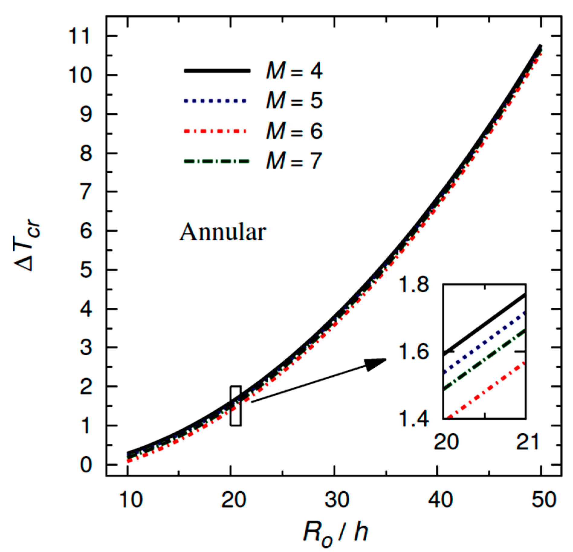
  • The differential quadrature method (DQM) showed a successful convergence;
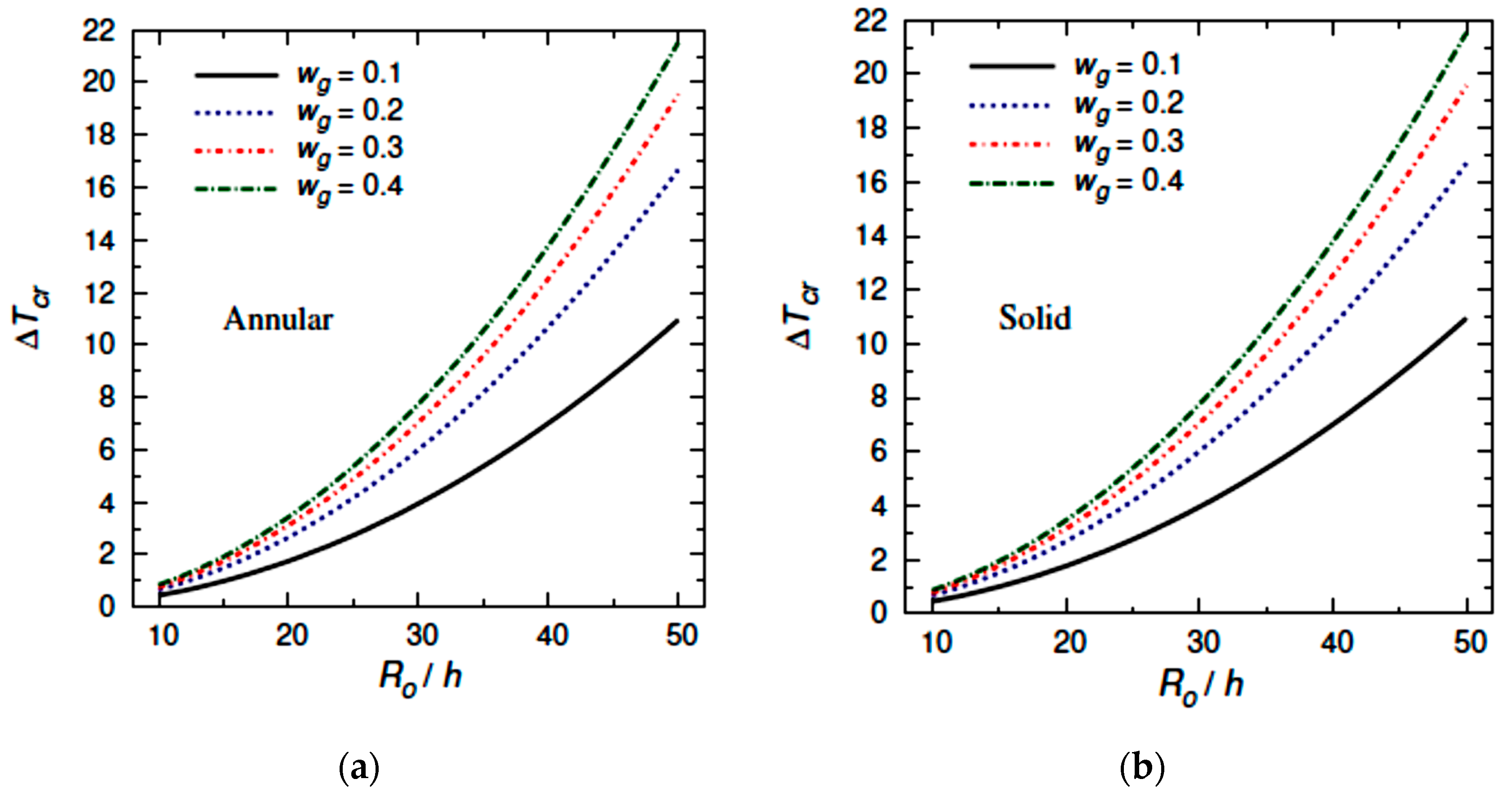
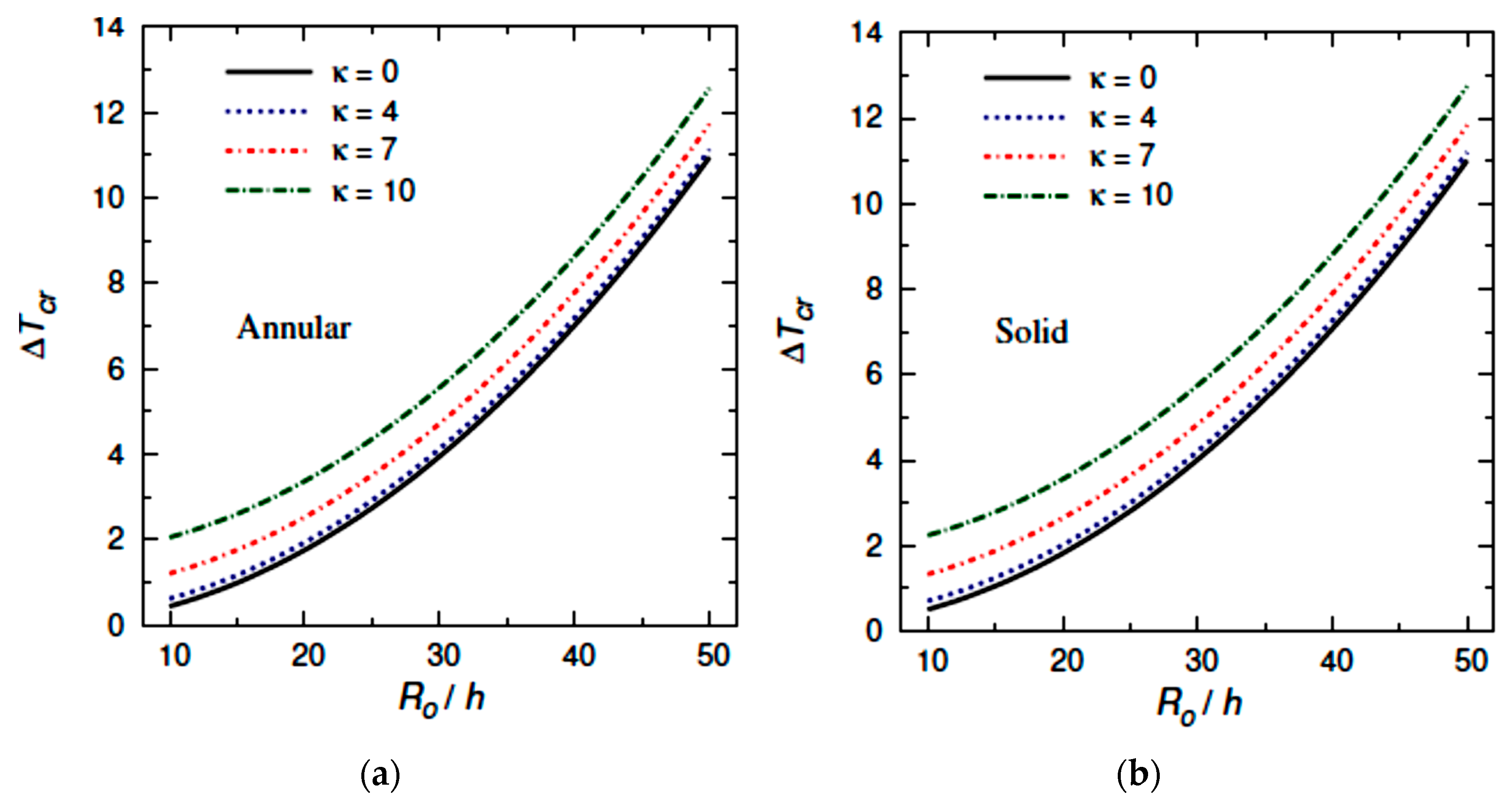
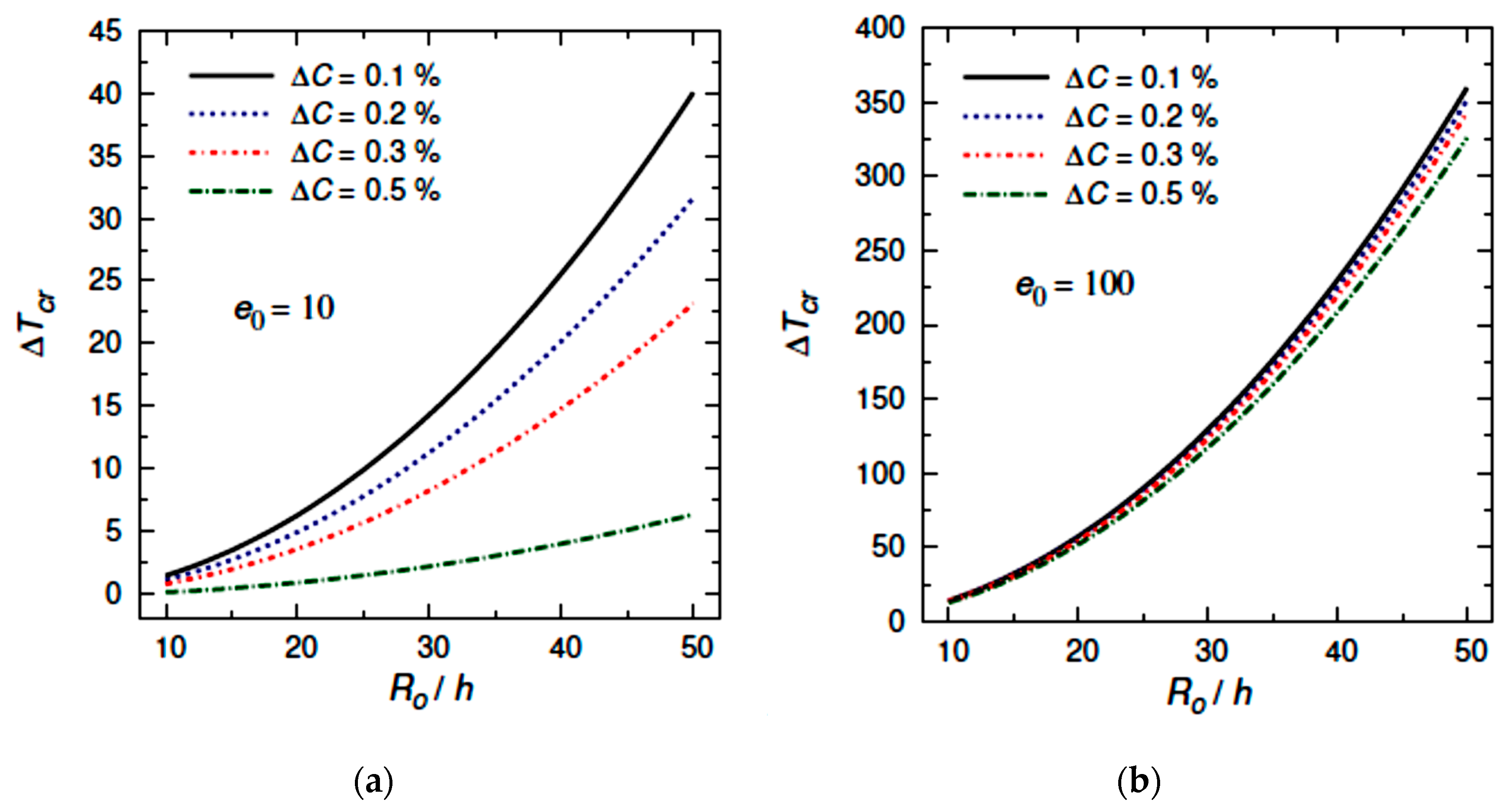
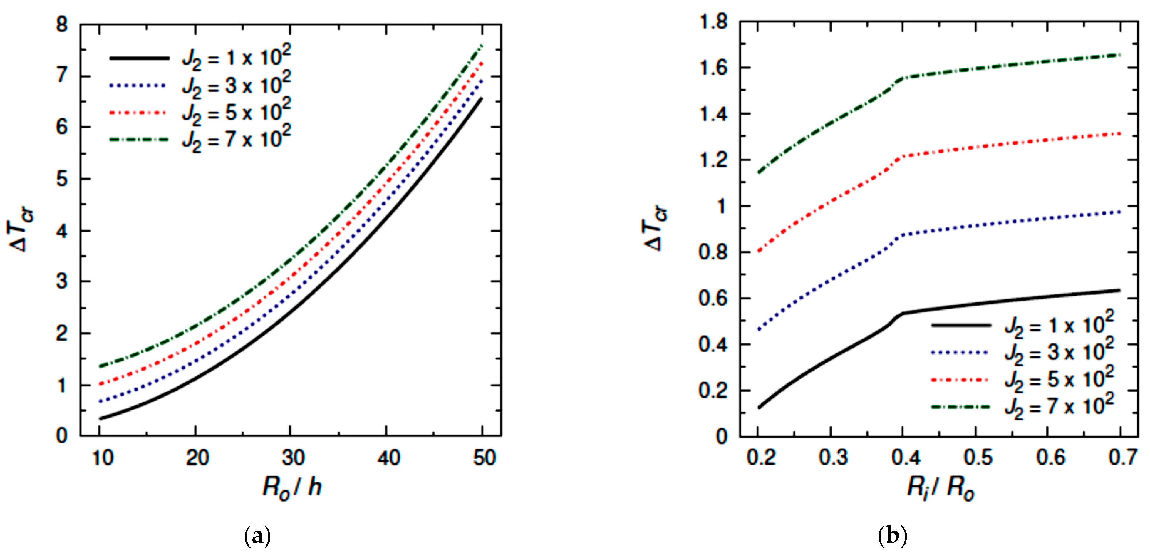
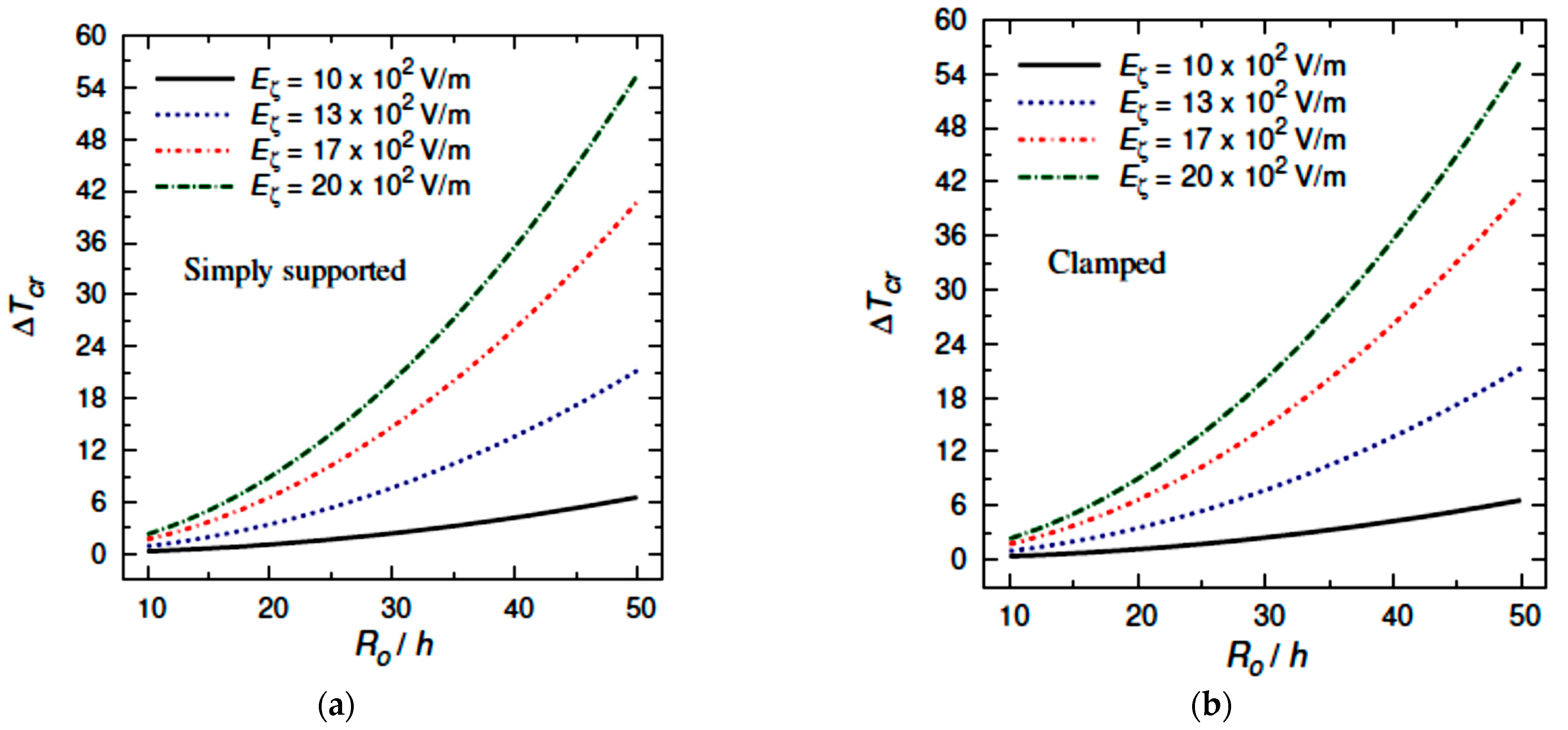
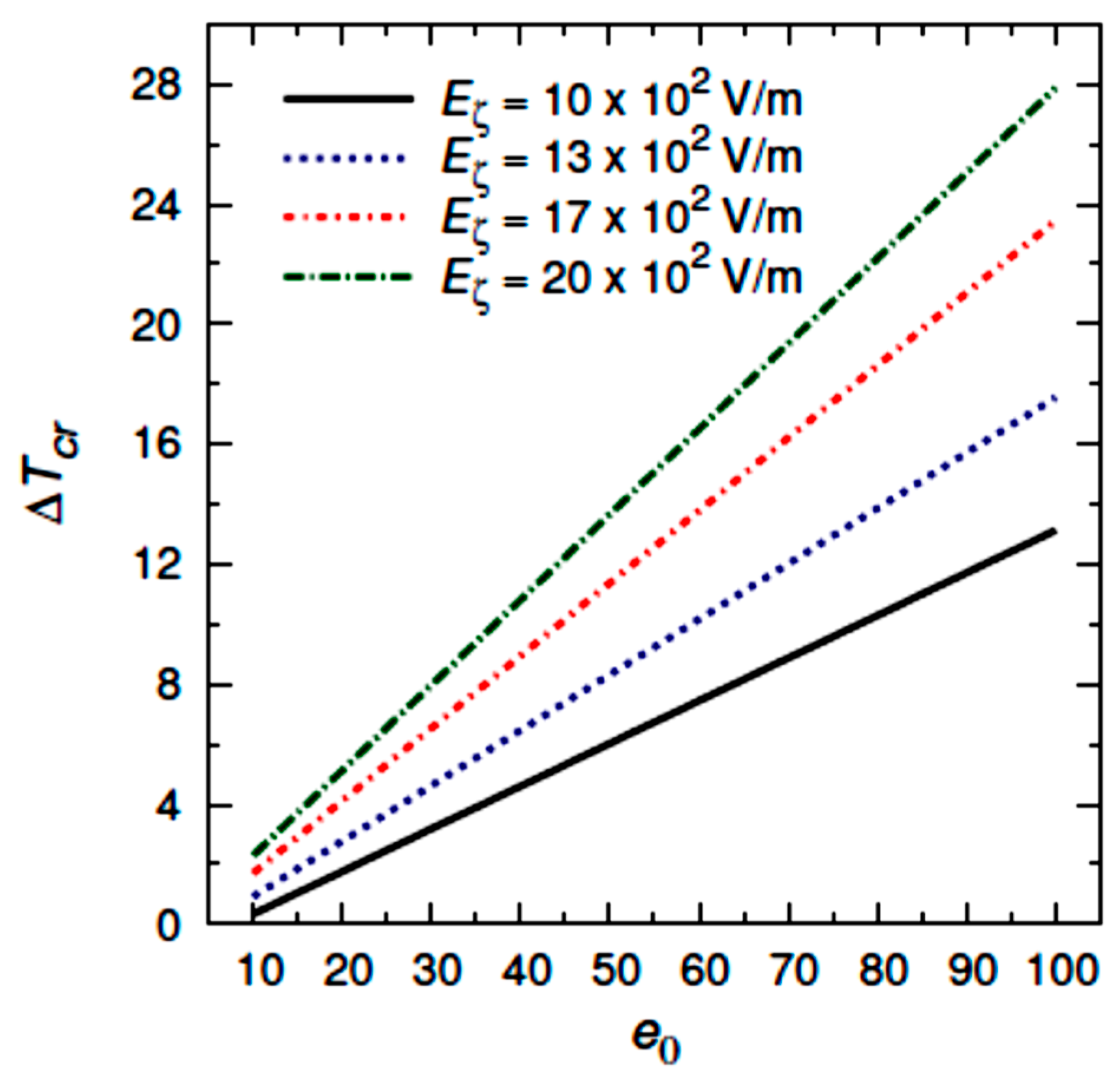
  • The critical buckling temperature increases monotonically with increasing the outer radius to thickness ratio for different values of graphene weight fraction, number of nodal diameters, moisture concentration, Winkler coefficient, Pasternak coefficient, and electric field;
  • The critical buckling temperature increases with a successful increase in graphene weight fraction, number of nodal diameters, Winkler coefficient, Pasternak coefficient, electric field, and piezoelectric multiple;
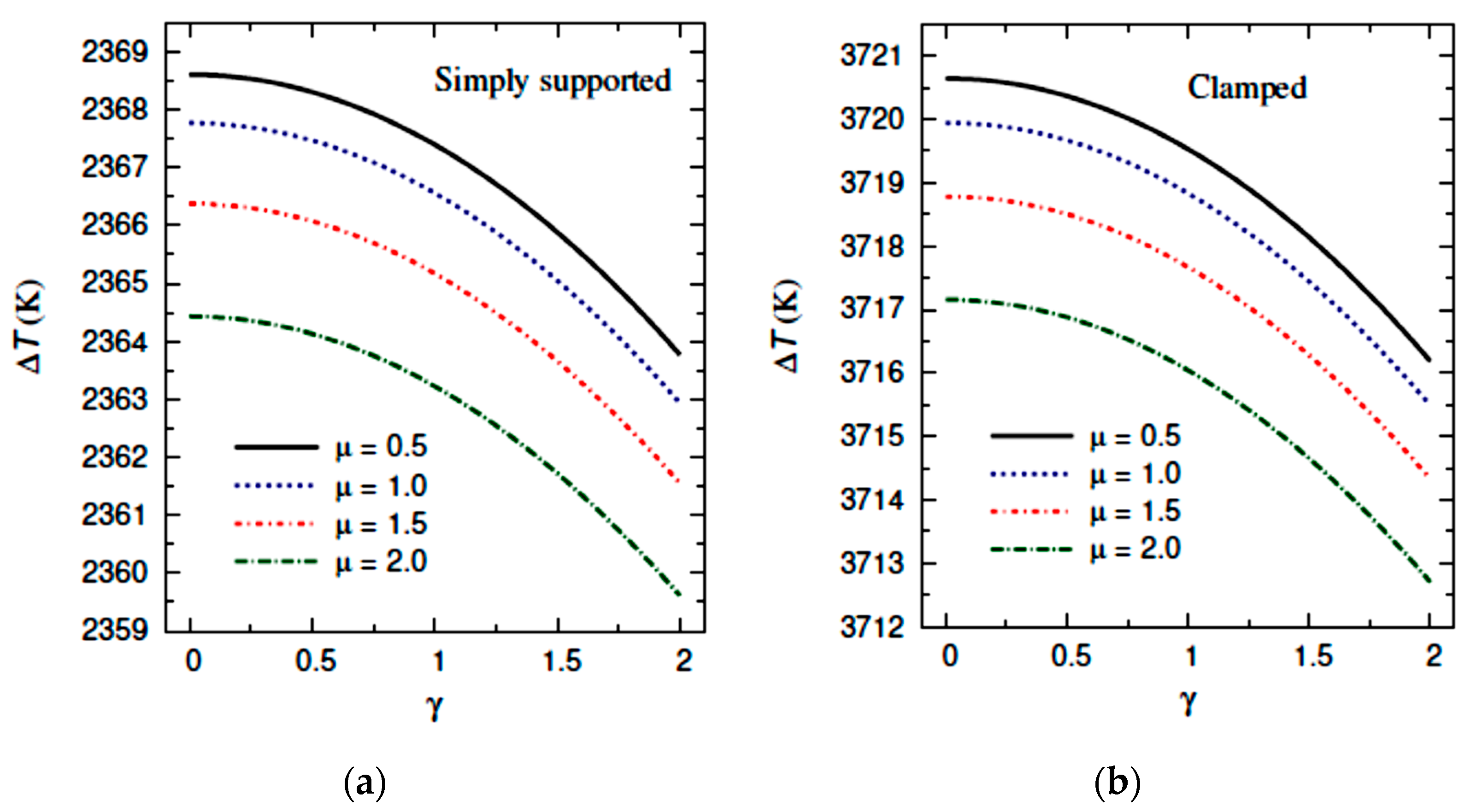
  • The critical buckling temperature increases when the nonlocal coefficient decreases for simply supported SGP plates, while it increases when the nonlocal coefficient increases in the case of clamped SGP plates;
  • The increment in graphene components and elastic foundation stiffness enhances the strength of the plates leading to an increment in the buckling temperature;
  • While the moisture conditions weaken the plate stiffness, therefore, the buckling temperature decreases as the moisture concentration increases;
  • Mechanical and thermal post-buckling analysis of sandwich circular smart graphene/piezoelectric annular plate with porous core may be considered for future work.

Author Contributions

Conceptualization, M.A.A., A.M.Z. and M.S.; data collection, M.A.A.; methodology, A.M.Z. and M.S.; software, A.M.Z. and M.S.; validation, A.M.Z. and M.S.; writing—original draft preparation, M.A.A., A.M.Z. and M.S.; writing—review and editing, M.A.A., A.M.Z. and M.S. All authors have read and agreed to the published version of the manuscript.

Funding

The authors extend their appreciation to the Deputyship for Research & Innovation, Ministry of Education in Saudi Arabia for funding this research work through the project number (IFPHI-034-135-2020) and King Abdulaziz University, DSR, Jeddah, Saudi Arabia.

Institutional Review Board Statement

Not applicable.

Informed Consent Statement

Not applicable.

Data Availability Statement

Not applicable.

Conflicts of Interest

The authors declare no conflict of interest.

References

  1. Sun, J.; Xu, X.; Lim, C.W.; Zhou, Z.; Xiao, S. Accurate thermo-electro-mechanical buckling of shear deformable piezoelectric fiber-reinforced composite cylindrical shells. Compos. Struct. 2016, 141, 221–231. [Google Scholar] [CrossRef]
  2. Wang, G.; Tan, J.; Zhao, Z.; Cui, S.; Wu, H. Mechanical and energetic characteristics of an energy harvesting type piezoelectric ultrasonic actuator. Mech. Syst. Signal Process. 2019, 128, 110–125. [Google Scholar] [CrossRef]
  3. Zhang, H.; Zhao, C.; Ning, X.; Huang, J.; Zhang, J. Harmonic excitation response performance and active regulation of the high-frequency piezoelectric ultrasonic transducer used in the thermosonic bonding for microelectronics. Sens. Actuators A Phys. 2020, 304, 111839. [Google Scholar] [CrossRef]
  4. Jia, H.; Li, H.; Lin, B.; Hu, Y.; Peng, L.; Xu, D.; Cheng, X. Fine scale 2-2 connectivity PZT/epoxy piezoelectric fiber composite for high frequency ultrasonic application. Sens. Actuators A Phys. 2021, 324, 112672. [Google Scholar] [CrossRef]
  5. Laasri, I.; Bybi, A.; Mouhat, O.; Jamal, M.; Hladky, A.C.; Ettahir, A.; Kettani, K. Investigation of the electrical limit conditions effects in piezoelectric transducer arrays utilized in medical imaging. Appl. Acoust. 2020, 170, 107509. [Google Scholar] [CrossRef]
  6. Bußmann, A.B.; Durasiewicz, C.P.; Kibler, S.H.A.; Wald, C.K. Piezoelectric titanium based microfluidic pump and valves for implantable medical applications. Sens. Actuators A Phys. 2020, 323, 112649. [Google Scholar] [CrossRef]
  7. Ederer, I.; Raetsch, P.; Schullerus, W.; Tille, C.; Zech, U. Piezoelectrically driven micropump for on-demand fuel-drop generation in an automobile heater with continuously adjustable power output. Sens. Actuators A Phys. 1997, 62, 752–755. [Google Scholar] [CrossRef]
  8. Kulkarni, H.; Zohaib, K.; Khusru, A.; Aiyappa, K.S. Application of piezoelectric technology in automotive systems. Mater. Today Proc. 2018, 5, 21299–21304. [Google Scholar] [CrossRef]
  9. Mason, W.P. Piezoelectricity, its history and applications. J. Acoust. Soc. Am. 1980, 68, S39. [Google Scholar] [CrossRef] [Green Version]
  10. Zhou, Y.; Zhu, J.; Liu, D. Dynamic analysis of laminated piezoelectric cylindrical shells. Eng. Struct. 2020, 209, 109945. [Google Scholar] [CrossRef]
  11. Moradi-Dastjerdi, R.; Behdinan, K.; Safaei, B.; Qin, Z. Buckling behavior of porous CNT-reinforced plates integrated between active piezoelectric layers. Eng. Struct. 2020, 222, 111141. [Google Scholar] [CrossRef]
  12. Abazid, M.A.; Sobhy, M. Thermo-electro-mechanical bending of FG piezoelectric microplates on Pasternak foundation based on a four-variable plate model and the modified couple stress theory. Microsyst. Technol. 2018, 24, 1227–1245. [Google Scholar] [CrossRef]
  13. Zenkour, A.M.; Sobhy, M. Nonlocal piezo-hygrothermal analysis for vibration characteristics of a piezoelectric Kelvin–Voigt viscoelastic nanoplate embedded in a viscoelastic medium. Acta Mech. 2018, 229, 3–19. [Google Scholar] [CrossRef]
  14. Napole, C.; Barambones, O.; Calvo, I.; Derbeli, M.; Silaa, M.Y.; Velasco, J. Advances in tracking control for piezoelectric actuators using fuzzy logic and hammerstein-wiener compensation. Mathematics 2020, 8, 2071. [Google Scholar] [CrossRef]
  15. Wang, G.; Wang, B.; Zhang, C. Fixed-time third-order super-twisting-like sliding mode motion control for piezoelectric nanopositioning stage. Mathematics 2021, 9, 1770. [Google Scholar] [CrossRef]
  16. Liu, T.; Li, C.; Wang, C.; Lai, J.W.; Cheong, K.H. A simple-FSDT-based isogeometric method for piezoelectric functionally graded plates. Mathematics 2020, 8, 2177. [Google Scholar] [CrossRef]
  17. Zenkour, A.M.; Aljadani, M.H. Buckling analysis of actuated functionally graded piezoelectric plates via a quasi-3D refined theory. Mech. Mater. 2020, 151, 103632. [Google Scholar] [CrossRef]
  18. Zenkour, A.M.; Alghanmi, R.A. Static response of sandwich plates with FG core and piezoelectric faces under thermo-electro-mechanical loads and resting on elastic foundations. Thin-Walled Struct. 2020, 157, 107025. [Google Scholar] [CrossRef]
  19. Novoselov, K.S.; Geim, A.K.; Morozov, S.V.; Jiang, D.; Zhang, Y.; Dubonos, S.V.; Grigorieva, I.V.; Firsov, A.A. Electric field effect in atomically thin carbon films. Science 2004, 306, 666–669. [Google Scholar] [CrossRef] [PubMed] [Green Version]
  20. Balandin, A.A.; Ghosh, S.; Bao, W.; Calizo, I.; Teweldebrhan, D.; Miao, F.; Lau, C.N. Superior thermal conductivity of single-layer graphene. Nano Lett. 2008, 8, 902–907. [Google Scholar] [CrossRef]
  21. Lee, C.; Wei, X.; Kysar, J.W.; Hone, J. Measurement of the elastic properties and intrinsic strength of monolayer graphene. Science 2008, 321, 385–388. [Google Scholar] [CrossRef]
  22. Frank, I.W.; Tanenbaum, D.M.; van der Zande, A.M.; McEuen, P.L. Mechanical properties of suspended graphene sheets. J. Vac. Sci. Technol. B Microelectron. Nanometer Struct. Process. Meas. Phenom. 2007, 25, 2558–2561. [Google Scholar] [CrossRef] [Green Version]
  23. Rafiee, M.A.; Rafiee, J.; Wang, Z.; Song, H.; Yu, Z.Z.; Koratkar, N. Enhanced mechanical properties of nanocomposites at low graphene content. ACS Nano 2009, 3, 3884–3890. [Google Scholar] [CrossRef]
  24. Sobhy, M. Magneto-electro-thermal bending of FG-graphene reinforced polymer doubly-curved shallow shells with piezoelectromagnetic faces. Compos. Struct. 2018, 203, 844–860. [Google Scholar] [CrossRef]
  25. Sobhy, M.; Zenkour, A.M. Vibration analysis of functionally graded graphene platelet-reinforced composite doubly-curved shallow shells on elastic foundations. Steel Compos. Struct. 2019, 33, 195–208. [Google Scholar]
  26. Arefi, M.; Bidgoli, E.M.R.; Rabczuk, T. Effect of various characteristics of graphene nanoplatelets on thermal buckling behavior of FGRC micro plate based on MCST. Eur. J. Mech.-A/Solids 2019, 77, 103802. [Google Scholar] [CrossRef]
  27. Thai, C.H.; Ferreira, A.J.M.; Tran, T.D.; Phung-Van, P. Free vibration, buckling and bending analyses of multilayer functionally graded graphene nanoplatelets reinforced composite plates using the NURBS formulation. Compos. Struct. 2019, 220, 749–759. [Google Scholar] [CrossRef]
  28. Zenkour, A.M.; Sobhy, M. Axial magnetic field effect on wave propagation in bi-layer FG graphene platelet-reinforced nanobeams. Eng. Comput. 2022, 38, 1313–1329. [Google Scholar] [CrossRef]
  29. Sobhy, M. 3-D elasticity numerical solution for magneto-hygrothermal bending of FG graphene/metal circular and annular plates on an elastic medium. Eur. J. Mech.-A/Solids 2021, 88, 104265. [Google Scholar] [CrossRef]
  30. Mao, J.J.; Lu, H.M.; Zhang, W.; Lai, S.K. Vibrations of graphene nanoplatelet reinforced functionally gradient piezoelectric composite microplate based on nonlocal theory. Compos. Struct. 2020, 236, 111813. [Google Scholar] [CrossRef]
  31. Kundalwal, S.I.; Shingare, K.B.; Gupta, M. Flexoelectric effect on electric potential in piezoelectric graphene-based composite nanowire: Analytical and numerical modelling. Eur. J. Mech.-A/Solids 2020, 84, 104050. [Google Scholar] [CrossRef]
  32. Wang, Y.; Feng, C.; Santiuste, C.; Zhao, Z.; Yang, J. Buckling and postbuckling of dielectric composite beam reinforced with Graphene Platelets (GPLs). Aerosp. Sci. Technol. 2019, 91, 208–218. [Google Scholar] [CrossRef]
  33. Wang, Y.; Feng, C.; Yang, J.; Zhou, D.; Liu, W. Static response of functionally graded graphene platelet–reinforced composite plate with dielectric property. J. Intell. Mater. Syst. Struct. 2020, 31, 2211–2228. [Google Scholar] [CrossRef]
  34. Wu, H.; Zhu, J.; Kitipornchai, S.; Wang, Q.; Ke, L.L.; Yang, J. Large amplitude vibration of functionally graded graphene nanocomposite annular plates in thermal environments. Compos. Struct. 2020, 239, 112047. [Google Scholar] [CrossRef]
  35. Zhao, S.; Zhao, Z.; Yang, Z.; Ke, L.; Kitipornchai, S.; Yang, J. Functionally graded graphene reinforced composite structures: A review. Eng. Struct. 2020, 210, 110339. [Google Scholar] [CrossRef]
  36. Feng, C.; Kitipornchai, S.; Yang, J. Nonlinear free vibration of functionally graded polymer composite beams reinforced with graphene nanoplatelets (GPLs). Eng. Struct. 2017, 140, 110–119. [Google Scholar] [CrossRef]
  37. Affdl, J.H.; Kardos, J.L. The Halpin-Tsai equations: A review. Polym. Eng. Sci. 1976, 16, 344–352. [Google Scholar] [CrossRef]
  38. Song, M.; Yang, J.; Kitipornchai, S. Bending and buckling analyses of functionally graded polymer composite plates reinforced with graphene nanoplatelets. Compos. Part B Eng. 2018, 134, 106–113. [Google Scholar] [CrossRef] [Green Version]
  39. Brush, D.O.; Almroth, B.O. Buckling of Bars, Plates, and Shells; McGraw-Hill: New York, NY, USA, 1975. [Google Scholar]
  40. Ke, L.L.; Liu, C.; Wang, Y.S. Free vibration of nonlocal piezoelectric nanoplates under various boundary conditions. Phys. E Low-Dimens. Syst. Nanostructures 2015, 66, 93–106. [Google Scholar] [CrossRef]
  41. Lim, C.W.; Zhang, G.; Reddy, J. A higher-order nonlocal elasticity and strain gradient theory and its applications in wave propagation. J. Mech. Phys. Solids 2015, 78, 298–313. [Google Scholar] [CrossRef]
  42. Khorshidvand, A.R.; Jabbari, M.; Eslami, M.R. Thermoelastic buckling analysis of functionally graded circular plates integrated with piezoelectric layers. J. Therm. Stresses 2012, 35, 695–717. [Google Scholar] [CrossRef]
  43. Meyers, C.A.; Hyer, M.W. Thermal buckling and postbuckling of symmetrically laminated composite plates. J. Therm. Stresses 1991, 14, 519–540. [Google Scholar] [CrossRef]
  44. Shariat, B.S.; Eslami, M.R. Buckling of thick functionally graded plates under mechanical and thermal loads. Compos. Struct. 2007, 78, 433–439. [Google Scholar] [CrossRef]
  45. Zenkour, A.M.; Sobhy, M. Thermal buckling of various types of FGM sandwich plates. Compos. Struct. 2010, 93, 93–102. [Google Scholar] [CrossRef]
  46. Sobhy, M. Size-dependent hygro-thermal buckling of porous FGM sandwich microplates and microbeams using a novel four-variable shear deformation theory. Int. J. Appl. Mech. 2020, 12, 2050017. [Google Scholar] [CrossRef]
  47. Wang, C.Y. On the buckling of a circular plate on an elastic foundation. Trans. -Am. Soc. Mech. Eng. J. Appl. Mech. 2005, 72, 795. [Google Scholar] [CrossRef]
  48. Shu, C. Differential Quadrature and Its Application in Engineering; Springer Science & Business Media: Berlin, Germany, 2012. [Google Scholar]
  49. Demir, O.; Balkan, D.; Peker, R.C.; Metin, M.; Arikoglu, A. Vibration analysis of curved composite sandwich beams with viscoelastic core by using differential quadrature method. J. Sandw. Struct. Mater. 2020, 22, 743–770. [Google Scholar] [CrossRef]
  50. Sobhy, M. Differential quadrature method for magneto-hygrothermal bending of functionally graded graphene/Al sandwich-curved beams with honeycomb core via a new higher-order theory. J. Sandw. Struct. Mater. 2021, 23, 1662–1700. [Google Scholar] [CrossRef]
  51. Mao, J.J.; Zhang, W. Buckling and post-buckling analyses of functionally graded graphene reinforced piezoelectric plate subjected to electric potential and axial forces. Compos. Struct. 2019, 216, 392–405. [Google Scholar] [CrossRef]
  52. Kiani, Y.; Eslami, M.R. An exact solution for thermal buckling of annular FGM plates on an elastic medium. Compos. Part B Eng. 2013, 45, 101–110. [Google Scholar] [CrossRef]
Figure 1. Configuration of a smart graphene/piezoelectric nanocomposite circular plate on an elastic substrate.
Mathematics 10 02638 g001
Figure 2. Convergence of the critical buckling temperature ΔTcr of simply supported SGP annular plates ( R i / R o = 0.3 , κ = 1, E ζ = 0.05   V / m , wg = 0.1%, μ = γ = 2   nm , Δ C = 0.5%, e0 = 3 × 10⁵, J 1 = 100 , J 2 = 10 ).
Mathematics 10 02638 g002
Figure 3. Effects of the outer radius to thickness ratio R o / h and graphene weight fraction w g on the critical buckling temperature Δ T c r of simply supported SGP (a) annular and (b) solid circular plates ( R i / R o = 0.7 , κ = 2 , E ζ = 0.05   V / m , μ = γ = 2   nm , Δ C = 0.5 % , e 0 = 3 × 10 5 , J 1 = 100 , J 2 = 10 ).
Mathematics 10 02638 g003
Figure 4. Effects of the outer radius to thickness ratio R o / h and number of nodal diameter κ on the critical buckling temperature Δ T c r   of simply supported SGP (a) annular and (b) solid circular plates ( R i / R o = 0.3 , E ζ = 0.05   V / m , w g = 0.1 % , μ = γ = 2   nm , Δ C = 0.5 % , e 0 = 3 × 10 5 , J 1 = 100 , J 2 = 10 ).
Mathematics 10 02638 g004
Figure 5. Effects of the outer radius to thickness ratio R o / h and moisture concentration Δ C on the critical buckling temperature Δ T c r of simply supported SGP annular plates for (a) e 0 = 10 and (b) e 0 = 100 ( R i / R o = 0.3 , κ = 1 , E ζ = 10 3   V / m , w g = 0.1 % , μ = γ = 2   nm , J 1 = 100 , J 2 = 10 ).
Mathematics 10 02638 g005
Figure 6. Effects of the Winkler coefficient J 1 on the critical buckling temperature Δ T c r of (a) simply supported and (b) clamped SGP annular plates ( R i / R o = 0.3 , κ = 1 , E ζ = 10 3   V / m , Δ C = 0.5 % , e 0 = 10 , w g = 0.1 % , μ = γ = 2   nm , J 2 = 10 ).
Mathematics 10 02638 g006
Figure 7. Critical buckling temperature Δ T c r of simply supported SGP annular plates versus (a) the outer radius to thickness ratio R o / h and (b) inner radius to outer radius ratio R i / R o for different values of Pasternak’s coefficient J 2 ( κ = 1 , E ζ = 10 3   V / m , Δ C = 0.5 % , e 0 = 10 , w g = 0.1 % , μ = γ = 2   nm , J 1 = 10 3 ).
Mathematics 10 02638 g007
Figure 8. Critical buckling temperature Δ T c r of (a) simply supported plates versus the ratio R o / h , (b) clamped plates versus the ratio R o / h , (c) simply supported plates versus the ratio R i / R o and (d) clamped plates versus the ratio R i / R o for different values of electric field ( κ = 1 , Δ C = 0.5 % , e 0 = 10 , w g = 0.1 % , μ = γ = 2   nm , J 1 = 1000 , J 2 = 100 ).
Mathematics 10 02638 g008aMathematics 10 02638 g008b
Figure 9. Effects of the piezoelectric multiple e 0 on the critical buckling temperature Δ T c r of simply supported SGP annular plates for different values of electric field E ζ ( R o / h = 10, R i / R o = 0.3, κ = 1 , Δ C = 0.5 % , w g = 0.1 % , J 1 = 10 3 , J 2 = 10 2 ).
Mathematics 10 02638 g009
Figure 10. Effects of the nonlocal coefficient μ and strain gradient coefficient γ on the critical buckling temperature Δ T c r of (a) simply supported and (b) clamped SGP annular plates ( R o / h = 3 , R i / R o = 0.3 , κ = 0 , E ζ = 5   V / m , Δ C = 1 % , e 0 = 10 , w g = 0.1 % , J 1 = 10 3 , J 2 = 10 2 ).
Mathematics 10 02638 g010
Table 1. Comparison of critical buckling temperature ΔTcr of isotropic homogeneous annular plates for different values of the inner radius to outer radius ratio R i R o and thickness to outer radius ratio R o / h ( ν = 0.3 ,   α = 7.4 × 10 6 K).
R i / R o Source κ h / R o = 0.010 h / R o = 0.015 h / R o = 0.020
0.10Ref. [52]139.00287.755156.009
Present139.04387.831156.436
0.15Ref. [52]243.22797.261172.908
Present243.37297.486173.091
Table 2. Critical buckling temperature Δ T c r of simply supported SGP annular and solid circular plates for different values of the moisture concentration Δ C , Winkler coefficient J 1 and Pasternak coefficient J 2 ( κ = 1 , E ζ = 10 3   V / m , e 0 = 10 , wg = 0.1%, μ = γ = 2   nm , R o / h = 10 , R i / R o = 0.4 ).
J 1 J 2 AnnularSolid
Δ C = 0.1 0.20.30.40.10.20.30.4
1 × 10 4 1002.413022.075051.737091.399122.326751.988781.650811.31284
3002.753372.415412.077441.739472.667102.329131.991161.65319
5003.093732.755762.417792.079823.007452.669482.331521.99355
7003.434083.096112.758142.420173.347803.009842.671872.33390
3 × 10 4 1003.508083.170112.832142.494172.879362.541392.203421.86545
3003.848433.510463.172492.834523.219712.881742.543772.20580
5004.188783.850813.512843.174873.560063.222092.884122.54615
7004.529134.191163.853203.515233.900413.562443.224472.88651
5 × 10 4 1004.603944.265973.928003.590033.425023.087052.749082.41111
3004.944294.606324.268353.930383.765373.427403.089432.75146
5005.284644.946674.608704.270734.105723.767753.429783.09182
7005.624995.287024.949054.611094.446074.108103.770143.43217
7 × 10 4 1005.699905.361935.023964.685993.969683.631713.293742.95577
3006.040255.702285.364315.026344.310033.972063.634093.29612
5006.380606.042635.704665.366694.650384.312413.974443.63647
7006.720956.382986.045015.707054.990734.652764.314793.97682
Table 3. Critical buckling temperature Δ T c r of simply supported SGP annular and solid circular plates for different values of the moisture concentration Δ C , graphene weight fraction w g and electric field E ζ ( κ = 1 , e 0 = 10 , J 1 = 10 3 , J 2 = 10 , μ = γ = 2   nm , R o / h = 10 , R i / R o = 0.4 ).
w g E ζ AnnularSolid
Δ C = 0.1 0.20.30.40.10.20.30.4
0.110001.731491.393521.055550.717581.766721.428751.090780.75281
12002.122361.784391.446421.108452.157591.819621.481651.14368
14002.513222.175251.837281.499322.548462.210491.872521.53455
16002.904092.566122.228151.890182.939322.601352.263391.92542
0.210001.428621.099530.770430.441341.485951.156860.827770.49868
12001.789091.460001.130900.801811.846421.517331.188240.85914
14002.149561.820461.491371.162282.206891.877801.548711.21961
16002.510022.180931.851841.522752.567362.238271.909171.58008
0.310001.286040.967700.649350.331001.320801.002450.684110.36576
12001.634081.315730.997390.679041.668841.350491.032140.71379
14001.982121.663771.345421.027072.016871.698531.380181.06183
16002.330162.011811.693461.375112.364912.046561.728221.40987
0.410001.169490.864420.559340.254271.164790.859720.554650.24957
12001.508241.203160.898090.593011.503541.198460.893390.58831
14001.846981.541911.236830.931761.842281.537211.232130.92706
16002.185731.880651.575581.270502.181031.875951.570881.26580
Publisher’s Note: MDPI stays neutral with regard to jurisdictional claims in published maps and institutional affiliations.

