Article

Numerical Study of MHD Natural Convection inside a Cubical Cavity Loaded with Copper-Water Nanofluid by Using a Non-Homogeneous Dynamic Mathematical Model

1
National School of Applied Sciences, Ibn Zohr University, Agadir 1136, Morocco
2
Mechanical Engineering Department, College of Engineering, University of Babylon, Hilla 51001, Iraq
3
Physics Department, College of Sciences Abha, King Khalid University, Abha 61321, Saudi Arabia
4
Research Laboratory of Metrology and Energy Systems, Energy Engineering Department, National Engineering School, Monastir University, Monastir 5033, Tunisia
5
Higher School of Sciences and Technology of Hammam Sousse, Sousse University, Hammam Sousse 4011, Tunisia
6
Department of Oil and Gas Engineering, Basrah University for Oil and Gas, Basrah 61019, Iraq
7
Department of Mathematics, National Institute of Technology Rourkela, Rourkela 769008, India
8
Faculty of Computer Science and Information Technology, Superior University, Lahore 54000, Pakistan
9
Department of Mechanical Engineering, College of Engineering, University of Hail, Hail 2440, Saudi Arabia
10
Laboratory of Metrology and Energy Systems, Department of Energy Engineering, University of Monastir, Monastir 5000, Tunisia
11
Department of Mechanical Engineering, College of Engineering at Wadi Addwaser, Prince Sattam Bin Abdulaziz University, Wadi Addwaser 11991, Saudi Arabia
12
Department of Mechanical Engineering, Faculty of Engineering, University of Khartoum, Khartoum 11111, Sudan
*
Author to whom correspondence should be addressed.
Mathematics 2022, 10(12), 2072; https://doi.org/10.3390/math10122072
Submission received: 14 May 2022 / Revised: 9 June 2022 / Accepted: 13 June 2022 / Published: 15 June 2022

Abstract

:
Free convective flow in a cubical cavity loaded with copper-water nanofluid was examined numerically by employing a non-homogeneous dynamic model, which is physically more realistic in representing nanofluids than homogenous ones. The cavity was introduced to a horizontal magnetic field from the left sidewall. Both the cavity’s vertical left and right sidewalls are preserved at an isothermal cold temperature (Tc). The cavity includes inside it four isothermal heating blocks in the middle of the top and bottom walls. The other cavity walls are assumed adiabatic. Simulations were performed for solid volume fraction ranging from (0 ≤ ϕ ≤ 0.06), Rayleigh number varied as (103 ≤ Ra ≤ 105), the Hartmann number varied as (0 ≤ Ha ≤ 60), and the diameter of nanoparticle varied as (10 nm ≤ dp ≤ 130 nm). It was found that at (dp = 10 nm), the average Nusselt number declines when Ha increases, whereas it increases as (Ra) and (ϕ) increase. Furthermore, the increasing impact of the magnetic field on the average Nusselt number is absent for (Ra = 103), and this can be seen for all values of (ϕ). However, when (dp) is considered variable, the average Nusselt number was directly proportional to (Ra) and (ϕ) and inversely proportional to (dp).

1. Introduction

The buoyancy-driven convection, sometimes called free convection, in an enclosed space, is one of the most studied phenomena in heat transfer. This traditional problem has attained increasable attention inside the research community [1]. This is not an instantaneous change, but it is due to the abundance of industrial applications of this problem in real life. Specimens of these applications cover the cooling of electronic equipment, nuclear reactor core, solar energy field, heat exchangers, drying and food technologies, and airplane cabin insulation [2,3,4,5]. Despite this enticing attention, the number of published papers concerned with the natural convection in a 3-D cavity is still few compared with their corresponding papers dealing with the two-dimensional one. This difference is due to the problem complexity and the long-running time to obtain suitable results. Samples of works that deal with the natural convection in a 3-D cavity loaded with water or air include Ghachem et al. [6], Onyango et al. [7], Hussein et al. [8], Al-Rashed et al. [9], and recently Alnaqi et al. [10].
From another perspective, the subject concerns the mixed influence of natural convection, and the magnetic field is magneto-hydrodynamic (MHD) natural convection. This subject has an important application in many fields such as geothermal energy, crystal growth in liquids, microelectronic equipment, plasma technology, hemodialysis, and metal casting [11,12,13].
On the other hand, the natural convection inside the cavities can be dramatically enhanced by replacing the traditional or base fluids (e.g., water) with another advanced fluid called the nanofluid [14]. The latter can be defined as a homogenous suspension of nanoparticles in a traditional fluid. The secret to this substitution is due to the high thermal conductivity of nanoparticles, which makes the nanofluid considerably better and more efficient as a result of their high thermal conductivity [15]. In the last ten years, the nanofluid has entered most medical, agricultural, industrial, and engineering applications such as solar energy, biological sciences, heat transfer equipment, environment, car, tractor radiators, transportation, water purification, and many others [16,17,18]. Some excellent literature surveys such as Hussein [19,20], Hussein et al. [21,22], Haddad et al. [23], Bahiraei and Hangi [24], and Kamel et al. [25] can be read for further background on the nanofluid and its applications.
However, few researchers have considered MHD natural convection of nanofluids inside cavities, such as Kolsi et al. [26,27,28], Al-Rashed et al. [29,30], and Sheikholeslami et al. [31,32].
Kolsi et al. [26] numerically simulated MHD free convection of CNT nanofluid in a cubical cavity having a cold inclined plate. The enclosure’s right sidewall was open, while the left was kept at an isothermal hot temperature. The rest walls were insulated. The results were displayed for the Hartmann number (0 ≤ Ha ≤ 100), Rayleigh number (103 ≤ Ra ≤ 105), the volumetric fraction (0 ≤ ϕ ≤ 0.05), and the inclination angle of the plate (0° ≤ θ ≤ 360°). They concluded that the influence of the inclined plate was substantial for the high Rayleigh number. Kolsi et al. [27] investigated free convection of MWCNT nanofluid in a differential heated cavity subjected to a periodic magnetic field. They examined the volumetric percentage, oscillation period, and Hartmann number at various values. The large Hartmann number reduced the heat transmission oscillation behavior. The impact of the horizontal or vertical magnetic field on the thermocapillary free convective flow of CNT nanofluid in a 3-D cavity was examined numerically by Kolsi et al. [28]. They modified the configuration of Kolsi et al. [27] by opening the upper wall. It was discovered that raising the solid volume fraction while reducing the Hartmann number increased the average Nusselt number.
Al-Rashed et al. [29] numerically analyzed MHD natural convection in a cubical enclosure filled with CNT-water nanofluid. Their study included two cases. The magnetic field was applied to the upper enclosure region in the first and the lower regions in the second. The enclosure was cooled from its right side and heated from the left side, whereas other walls were kept insulated. They concluded that the magnetic field’s position and strength influenced natural convection. Al-Rashed et al. [30] considered the same problem and the configuration by Al-Rashed et al. [29]. The sole difference was the enclosure was subjected to a tilted magnetic field. The authors presented the flow and thermal fields for different magnetic field orientation angles, Hartmann and Rayleigh numbers, and the solid volumetric fraction. The authors concluded that the orientation angle effect was dominant at (Ra = 105).
Sheikholeslami and Ellahi [31] studied the MHD natural convective flow in a 3-D cavity loaded with alumina-water nanofluid by means of numerical simulation. The upper and lower walls were kept at isothermal cold and hot temperatures, respectively, while the rest of the walls were insulated. The hydrothermal behavior of the natural convection was examined for various values of the solid volumetric fraction, Rayleigh, and Hartmann numbers. They deduced that the average Nusselt number declined by decreasing the solid volume fraction and Rayleigh number and increasing the Hartmann number. Sheikholeslami et al. [32] utilized the Lattice Boltzmann approach to examine the characteristics of the natural convection inside a 3-D enclosure subjected to the magnetic field effect. The cavity was loaded with water-based alumina nanofluid. Their results were illustrated for Hartmann number ranging from (0 ≤ Ha ≤ 100), Rayleigh number ranging from (103 ≤ Ra ≤ 105), and the solid volumetric fraction varied as (0 ≤ ϕ ≤ 0.04). They concluded that the nanofluid was more efficient for low Rayleigh and high Hartmann numbers.
In fact, the traditional homogeneous model of the nanofluid is based on the assumption that nanofluid is treated as usual fluid. Therefore, the governing equations of the mass, momentum, and energy are utilized, taking into account the effective constant properties of the nanofluid. On the other hand, the non-homogeneous dynamic model is a new model developed by Uddin et al. [33,34]. It is assumed that the transport of nanoparticles is due to the relative velocity between the base fluid and the nanoparticles. The model was named as non-homogeneous dynamic model due to the non-homogeneity of the nanofluid caused by the Brownian and thermophoresis diffusions. It includes the correlations of thermo-physical properties of nanofluids, the thermal diffusion coefficient equation, and the buoyancy effect. Moreover, it also includes the concentration equation of nanofluids so that their concentration effect can be taken into account. The reader can be referred to [35,36,37] for further information about this model.
The non-homogeneous dynamic model was used by different researchers to explore the free convection of nanofluids in square containers. Sheikhzadeh et al. [38] numerically researched the nanoparticles’ transport impacts on the natural convection in a differential heated square cavity loaded with water-based alumina nanofluid. They found that natural convection decreased with the nanoparticles’ size and bulk volumetric fraction increment. The natural convection in a differential heated square cavity loaded with CuO-water nanofluid was addressed by Choi et al. [39]. They deduced that the average Nusselt number was enhanced by decreasing the solid volumetric fraction for both considered models for the constant Rayleigh number. Alsabery et al. [40] explored the free convection of water-based alumina nanofluid inside a square enclosure containing a solid conducting block. The upper wall was cold, whereas an isothermal heater was located in the lower-left corner. The rest of the lower and right walls were assumed insulated. The findings were displayed for a broad variety of the solid block’s thermal conductivity, thickness, Rayleigh number, and solid volumetric fraction. They noticed that the block size variation influenced the natural convection. Al-Balushi et al. [41] explored the transient natural convection in a square enclosure loaded with various kinds of nanofluid-containing magnetic nanoparticles (i.e., Fe3O4, Co-Fe2O4, Mn-Zn Fe2O4, and SiO2). The top and bottom walls were kept at constant cold and hot temperatures, respectively, whereas the vertical sidewalls were adiabatic. The results were presented for various values of Rayleigh number, nanoparticles shape factor, and volumetric fraction. It was found that the average Nusselt number intensified as the solid volumetric fraction and Rayleigh number increased. In addition, it was improved when using blade-shaped nanoparticles.
Other researchers used the non-homogeneous dynamic model to examine the MHD natural convection of nanofluids inside different containers. Uddin et al. [42] numerically explored the natural convection in a quarter-circular enclosure loaded with various types of nanofluid. The left vertical sidewall of the enclosure was assumed adiabatic, and the bottom wall was heated under a variable thermal condition, while the round wall was kept cold. The enclosure was exposed to a magnetic field with an inclination. It was found that the average Nusselt number was enhanced by increasing the inclination angle of the magnetic field, Rayleigh number, and the solid volumetric fraction. The numerical analysis of the transient natural convection in a semi-circular enclosure loaded with various types of nanofluid was carried out by Uddin and Rahman [43]. They concluded that lowering the nanoparticle’s diameter increased the average Nusselt number. In addition, it was noted that the nanoparticles were uniformly suspended in the base fluid when the range of their diameter (1 ≤ dp ≤ 10 nm). Uddin and Rasel [44] numerically analyzed the natural convection of copper oxide-water nanofluid inside a trapezoidal vessel. The top and bottom walls were considered adiabatic and hot, respectively. Whereas its left and right inclined sidewalls were subjected to cold temperature. It was noted that the natural convection diminished when the nanoparticles diameter was in the range of (1 ≤ dp ≤ 10 nm).
Recently, Alsabery et al. [45] explored free convection in a tilted 3D wavy cavity loaded with alumina-water nanofluid by using the non-homogeneous equilibrium model. The left wall of the cavity was considered cooled, whereas its right wavy wall was kept heated. The remaining walls were considered thermally insulated. The characteristics of the flow and thermal fields were illustrated for various values of the orientation angle, solid volumetric fraction, number of undulations, and Rayleigh number. They noticed an augmentation in the average Nusselt number when the orientation angle was more than 90°. Other useful references can be found in Refs. [46,47,48,49].
According to the published literature review results and the best of the authors’ knowledge, no work has been conducted to date that studies the MHD natural convection in a cubical cavity filled with copper-water nanofluid using a non-homogeneous dynamic model of the fluid. This kind of problem is worth studying as it is of essential interest in practical engineering applications such as compact heat exchangers and nuclear reactors. Furthermore, the influence of four isothermal heating blocks inside the cavity was also considered. Therefore, the main purpose of the current endeavor is to examine this genuine problem in great depth and detail. The physical aspect of the present study is to analyze the effect of the magnetic field on the natural convection in a cubical cavity when the nanoparticle diameter is considered either fixed or variable from a physical engineering point of view.
In this study, a mathematical formulation of the problem is given in Section 2. Section 3 presents the numerical solution procedure and the validation of the model. Section 4 reports the obtained simulation results, while detailed discussions of the results are given in Section 5. Finally, the conclusions of the study are given in Section 6.

2. Mathematical Model

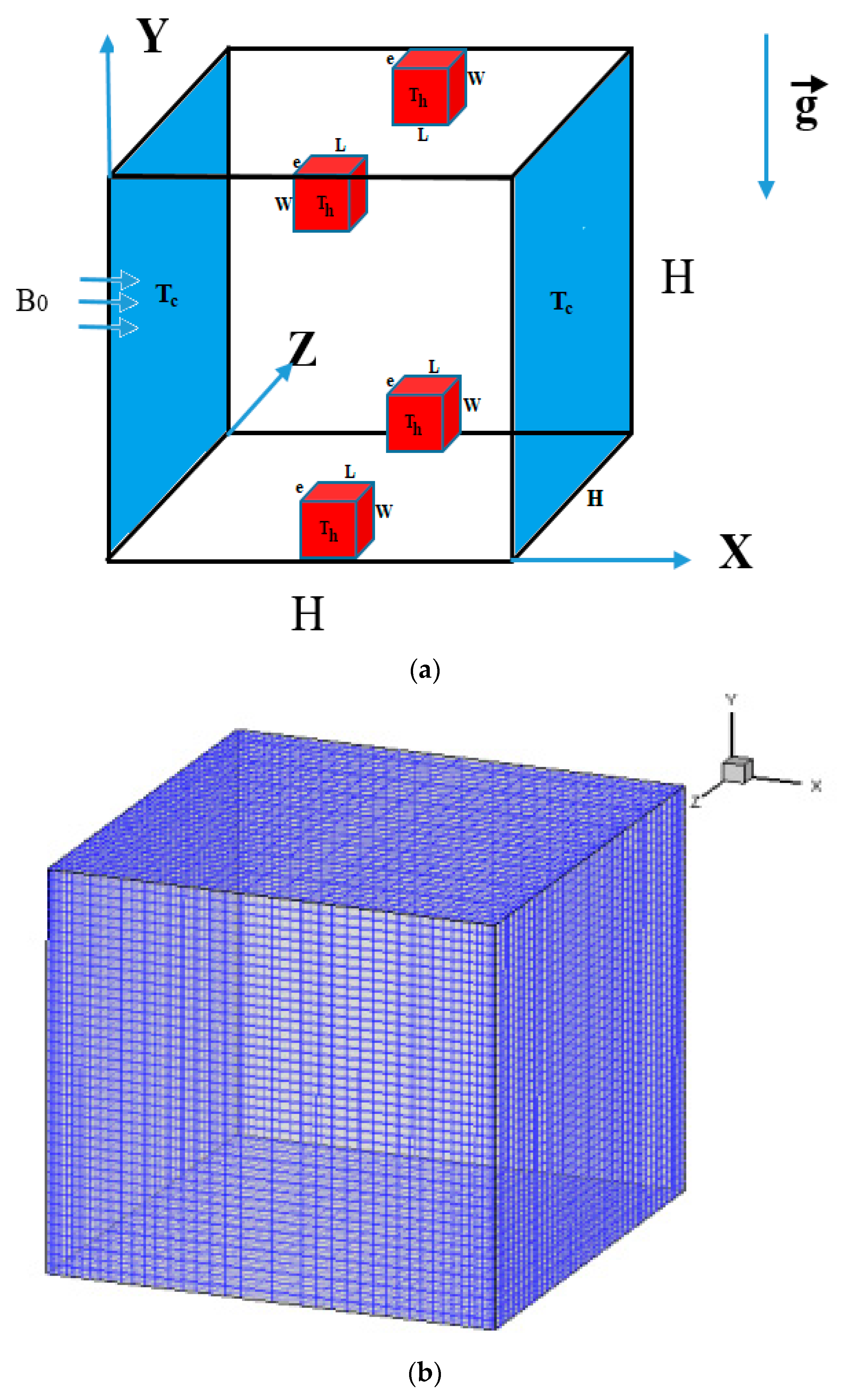
2.1. Problem Geometry, Assumptions, and Governing Equations

The present problem geometry with its Cartesian coordinate system is depicted in Figure 1. It consists of a 3-D cavity of equal height, width, and depth (H) and is exposed to a horizontal magnetic field (Bo) from its left sidewall. The cavity was loaded with copper-water nanofluid. The cavity’s vertical sidewalls were kept at an isothermal cold temperature (Tc). The cavity includes four isothermal heating blocks inside it positioned at the center of the top and bottom walls. Together with the remaining parts of the top and bottom walls, the other walls are assumed adiabatic. Table 1 includes the thermophysical characteristics of the water and copper nanoparticles.
To solve the governing equations, it is necessary to make the following assumptions:
  • The flow is assumed laminar, steady, Newtonian, 3D, and incompressible.
  • The viscous dissipation, chemical reaction, and thermal radiation effects are negligible.
  • Boussinesq approximation was adopted.
  • Non-homogeneous dynamic mathematical model was taken into account.
  • Brownian motion, nanofluid concentration, and thermophoresis are studied and considered.
  • The conduction heat transfer in walls was considered negligible.
When stated in their dimensionless form, the equations of continuity, momentum, and energy read [33,34]:
U U X + V U Y + W U Z = ρ f ρ n f P X + μ n f ν f ρ n f P r 2 U X 2 + 2 U Y 2 + 2 U Z 2
U V X + V V Y + W V Z = ρ f ρ n f P Y + μ n f ν f ρ n f P r 2 V X 2 + 2 V Y 2 + 2 V Z 2 + ρ β n f β f ρ n f R a T P r θ + R a C P r Φ H a P r V
U W X + V W Y + W W Z = ρ f ρ n f P Z + μ n f ν f ρ n f P r 2 W X 2 + 2 W Y 2 + 2 W Z 2
U θ X + V θ Y + W θ Z = α n f α f 2 θ X 2 + 2 θ Y 2 + 2 θ Z 2 + 1 L e Φ X θ X + Φ Y θ Y + Φ Z θ Z + P r N T B T S C θ X 2 + θ Y 2 + θ Z 2
U Φ X + V Φ Y + W Φ Z = P r S C 2 Φ X 2 + 2 Φ Y 2 + 2 Φ Z 2 + P r N T B T C S C 2 θ X 2 + 2 θ Y 2 + 2 θ Z 2 + P r N T B T S C Φ X θ X + Φ Y θ Y + Φ Z θ Z
It is possible to define the non-dimensional parameters that are present in Equations (1)–(6) as follows [41]:
U = u H α f ,   V = v H α f ,   W = w H α f ,   X = x H ,   Y = y H ,   Z = z H ,   Φ = C C C Δ C θ = T T C Δ T ,   P = p H 2 ρ f α f 2 P r = ν f α f ,   N T B T = D T D B Δ T T C ,   R a T = β f g H 3 Δ T ν f α f ,   R a C = ρ β f g H 3 Δ C ρ n f ν f α f N T B T C = D T D B Δ T Δ C C C T C ,   S C = μ f ρ f D B ,   L e = k f C C ρ C p f D B Δ C   and H a = B 0 H σ n f ρ n f ν f
where T C = T = 300   K , D B = k B T 3 π μ f d p and D T = 0.26 k f 2 k f + k p μ f ρ f T ϕ .
The following data are considered in the present work:
L e = 4.3713 × 10 5 ,   S C = 29,890 ,   D B = 3.3654 × 10 11 ,   D T = 3.9806 × 10 12 ,   N T B T C = 0.39429 ,   N T B T = 0.0039427 . P r = 6.8377 ,   Δ T = 10   K ,   Δ C = 0.01 ,   T C = T = 300 K ,   C C = 1   and   H a = 0 ,   30   and   60 .
dp = 10, 70 and 130 nm.
In the present work, the effective density ( ρ n f ), thermal expansion coefficient ( β ) n f , heat capacitance ( ρ C p ) n f , and thermal diffusivity ( α n f ) of the nanofluid are defined as [50,51,52]:
ρ n f = ( 1 ϕ ) ρ f + ϕ ρ n p
β n f = 1 ϕ β f + ϕ β n p
ρ C p n f = 1 ϕ ρ C p f + ϕ ρ C p n p
α n f = k n f ρ C p n f
The Brinkman model is used to calculate the viscosity of the nanofluid, which is regarded as a function of the solid volumetric fraction [53]:
μ n f = μ f ( 1 ϕ ) 2.5
Whilst Maxwell correlations of the nanofluid thermal conductivity are taken into account in the current work [54]:
k n f k f = ( k n p + 2 k f ) 2 ϕ ( k f k n p ) ( k n p + 2 k f ) + ϕ ( k f k n p )
The nanofluid thermal conductivity is also defined by including the shape factor of nanoparticles as follows [42]:
k n f k f = k n p + n 1 k f n 1 k f k n p ϕ k n p + n 1 k f + ϕ k f k n p
where n = 3 ψ . The symbol ( ψ ) is called the sphericity of the nanoparticle and represents the ratio of the sphere’s surface area to the real particle’s surface area with equal volumes.
The electrical conductivity of the nanofluid is defined by [55]:
σ n f = 1 ϕ σ f + ϕ σ n p
The local Nusselt number reads:
N u l Y , Z = k n f k f θ X
The average Nusselt number, Nua, is calculated as the integral of the temperature flux through the vertical right cold wall and is written as:
N u a = k n f k f S θ · e x d y d z

2.2. Boundary Conditions

The non-dimensional boundary conditions for the current work are given by the following expression:
For both left and right cold sidewalls,
U = V = W = 0 , θ = 0 and Φ = 0
At the four isothermal heating blocks,
U = V = W = 0 , θ = 1 and Φ = 1
For all adiabatic walls,
U = V = W = 0 and θ n = 0 .

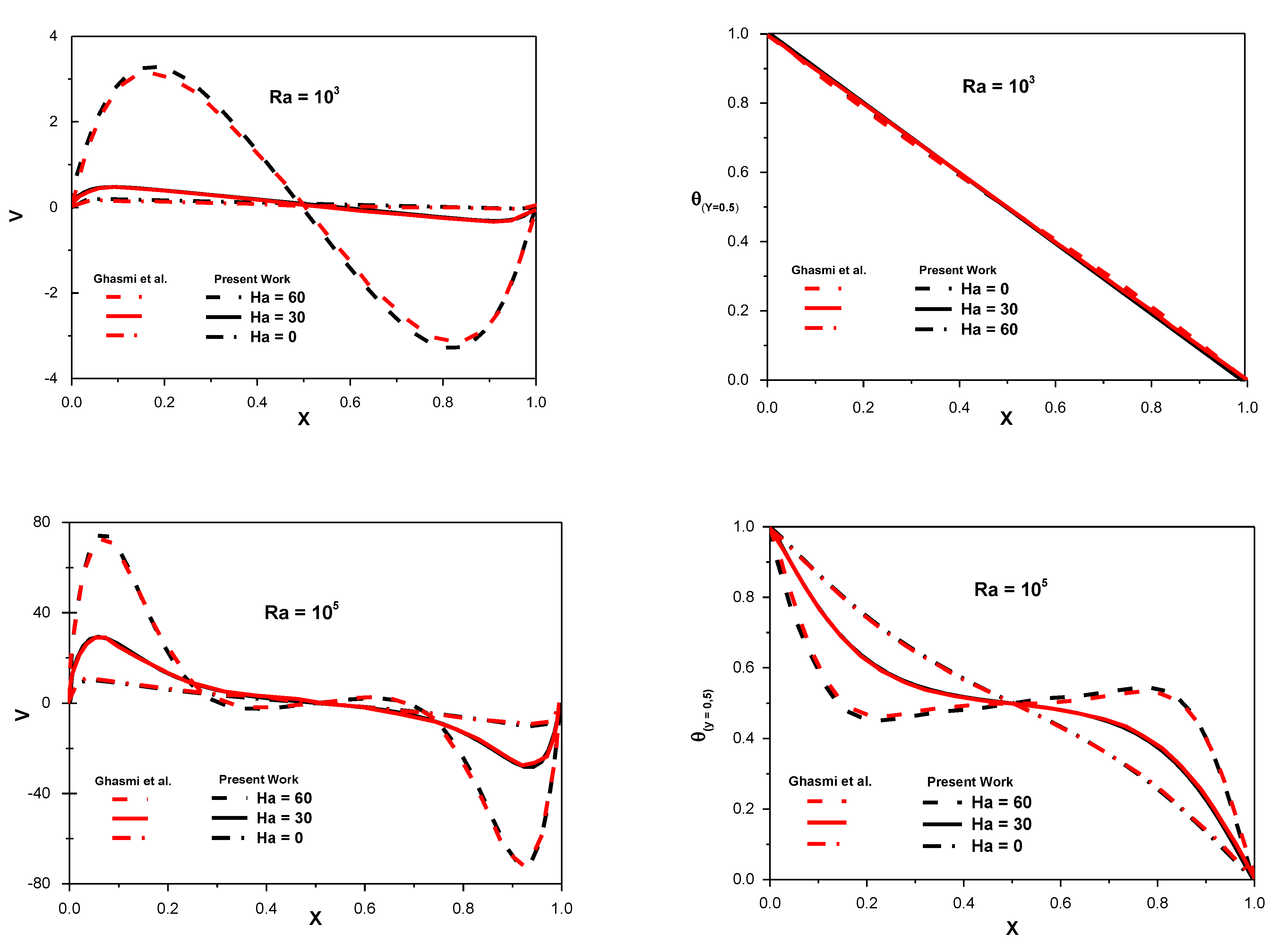
3. Numerical Solution, Validation and Grid-Independent Test

The mathematical model used in this work is based on the conservation of mass, momentum, and energy equations. The finite volume technique is employed to discretize these equations in conjunction with the power-law scheme. The SIMPLEC algorithm is used for solving the momentum equations in conjunction with the continuity equation. The generated discrete algebraic system is resolved using the Alternating Direction Implicit technique (ADI). For the purpose of solving the resulting system of algebraic equations as well as the boundary conditions, the Thomas Algorithm is employed. This numerical method is applied in this research as it is easy to implement and gives more accurate results compared to other methods.
To validate the numerical approach used in this study, the MHD natural convection in a differential heated square enclosure loaded with alumina-water nanofluid reported by Ghasemi et al. [54] is resolved using the same code used in this work. Excellent agreement was established for velocity, temperature, and isotherms between the two papers, as illustrated in Figure 2 and Figure 3.
Furthermore, various grid tests are carried out, and it is found that the grid (71 × 71 × 71) is enough to ensure that the computations are independent on the selected grid. Finally, a validation check is performed and presented in Table 2. This table disclosed that the current algorithm has an excellent agreement with the previously published data.

4. Results

This section presents the findings of the numerical analysis conducted in the present work. In the current study, the Hartmann number ranged as (0 ≤ Ha ≤ 60), the Rayleigh number is varied as (103 ≤ Ra ≤ 105), the volumetric fraction is varied as (0 ≤ ϕ ≤ 0.06), and the diameter of nanoparticle varied as (10 nm ≤ dp ≤ 130 nm).
Figure 4 presents the flow (top) and thermal (bottom) structures inside the cubical cavity filled with pure water [ϕ = 0 (solid line)] and Cu-water nanofluid [ϕ = 0.04 (dash line)] for various values of (Ha) and (Ra = 105). In this case, the nanoparticle diameter is considered fixed at (dp = 10 nm). The first row of Figure 4 represents a 2D pattern of streamlines drawn at the (Y-Z) plane, while the second and the third rows represent the three and two-dimensional pattern of isotherms, respectively.
Figure 5 depicts the fluctuation in temperature profiles along the X-axis for various Rayleigh number, Hartmann number, and solid volumetric fraction values. These profiles are drawn at the midsection of the vertical and axial axes (i.e., Y = Z = 0.5) and when the nanoparticle diameter is constant at (dp = 10 nm).
The impact of the Hartmann number and the solid volumetric fraction on the velocity profiles along the X-axis (left) and Y-axis (right) at three different values of (Ra) and (dp = 10 nm) was illustrated in Figure 6. These profiles are drawn at (Z = 0.5). With respect to the horizontal velocity profiles [U (X, 0.5, 0.5)].
The influence of the Rayleigh and Hartmann numbers on the local Nusselt number at the cavity’s left cold sidewalls (NuL) is seen in Figure 7 for (dp = 10 nm and ϕ = 0.02).
The link between the average Nusselt number and the solid volumetric fraction was depicted in Figure 8 for various Ra and Ha numbers and for (dp = 10 nm).
The flow structure at (Y-Z) plane and (X = 0.5) inside the cavity filled with pure water [ϕ = 0 (solid line)] and Cu-water nanofluid [ϕ = 0.04 (dash line)] for various values of (Ra) and (dp) was presented graphically at Figure 9. In this case, the Hartmann number is considered constant at (Ha = 30).
The temperature profiles variation along Y-axis for different values of (Ra) and (dp) at (Ha = 30 and ϕ = 0.04) were presented in Figure 10. All these profiles are displayed at (X = Z = 0.5).
The relationship between the maximum stream function and the solid volumetric fraction for various values of (Ra) and (dp) at (Ha = 30) were portrayed in Figure 11.
Figure 12 displays the variation of the velocity profiles along the Y-axis for different Ra and dp at (Ha = 30 and ϕ = 0.04). These profiles are drawn at (X = Z = 0.5).
The fluctuation in the average Nusselt number and the solid volumetric fraction for various values of (Ra) and (dp) at (Ha = 30) is depicted in Figure 13.

5. Discussion

Detailed analysis of the obtained numerical results, which were presented in Section 5, is discussed in this section.

5.1. When the Nanoparticle Diameter Is Considered Fixed at (dp = 10 nm)

Generally, Figure 4 shows that the flow field in the cavity is initiated at the bottom wall adjacent to the two isothermal heating blocks embedded inside it. After that, it begins to move parallel to the cavity’s cold left and right sidewalls until it reaches another two heating blocks in the top wall. The flow field can be observed from the 2D pattern drawn in the mid of the X-axis (X = 0.5), and its structure was displayed at the (Y-Z) plane. The reason for choosing the plane (X = 0.5, Y, Z) can be returned to its unique location, perpendicular to both the top and bottom walls containing the heating blocks. So, this plane is very useful to represent the fluid motion and the heat transfer inside the cavity distinctively. When the effect of the magnetic field is considered negligible (Ha = 0), the streamlines (first row) are accumulated intensely beside the heating blocks in the bottom wall. The shape of streamlines is seemed to be irregular, close to each other, and such as a curve, especially in the middle of the (Y-Z) plane. Both water and nanofluids exhibit this behavior. However, the effect of the water is better than nanofluid, especially near the top wall. The same pattern can also be noticed adjacent to the corresponding blocks in the top wall.
All these signals are due to the influential behavior of the natural convection at (Ha = 0). Now, when the magnetic field exists (30 ≤ Ha ≤ 60), a noticeable inflection in the flow field pattern is noticed inside the plane (X = 0.5, Y, Z). The streamlines begin to diverge from each other and become approximately linear and uniform, especially in the core of the (Y-Z) plane. When the Hartmann number rises to (Ha = 60), the intensity of the magnetic field increases, and this can be approved from the evident divergence between the streamlines as a result of the dominance of the Lorentz force generated by the magnetic field, which leads to slow the strength of the flow circulation inside the cavity. Both water and nanofluids exhibit this behavior.
In terms of the thermal field, the 3D pattern of isotherms (first row) clearly indicates that the temperature next to the heating blocks in the top and bottom walls drops as (Ha) grows from 0 to 100. The same decrease can be detected in the core of the cavity. For the 2D pattern of isotherms (second row), it was seen again that the temperature decreases faster inside the (Y-Z) plane as the Hartmann number increases. This can be confirmed by the rapid increase of the cold region inside this plane. In addition, the thermal plume, which can be observed around the heating blocks in the four corners of the (Y-Z) plane, begins to weaken and disappear gradually as (Ha) increases. As discussed previously, this is a normal reaction to the predominant effect of heat conduction with increasing (Ha).
As could be seen in Figure 5, for low Ra number (e.g., Ra = 103), for all studied values of (Ha) and (ϕ), there is a high agreement between the temperature profiles. In this case, the shape of the profiles is uniform, symmetrical, and seems similar to a semi-ellipse. Therefore, the rise in (Ha) and (ϕ) has no noticeable influence on the temperature profile in the cavity. This high similarity between the temperature profiles can be attributed to the weak influence of the convection at low Ra or when the conduction is dominant. The maximum temperature distribution is noticed at the midplane of the X-axis (X = 0.5). However, when the value of the Ra rises to Ra = 104 and 105, the simultaneous profiles which are noticed at (Ra = 103) begin to diverge from each other. The reason beyond this behavior is due to the increase in the buoyancy force and hence the natural convection in this case.
For (Ra = 104), as seen in Figure 5, the temperature reaches its highest value when the magnetic field is absent (Ha = 0). Since the influence of convection within the cavity is very strong in this scenario. However, as the Hartmann number rises to (Ha = 30 and 60), the temperature values gradually decrease and match each other. This is because the magnetic field effect increases, which results in a decrease in temperature as a result of convection damping. The impact of the solid volumetric fraction on the temperature profiles can be seen to decrease as the solid volumetric fraction increases from ϕ = 0 to 0.04. This action is exhibited when no magnetic field is present (Ha = 0). While for (Ha = 30 and 60), the increase of the solid volumetric fraction has very slight effects on the temperature profiles. Therefore, it can be concluded that the water (ϕ = 0) is better than the nanofluid (0.02 ≤ ϕ ≤ 0.04), when the magnetic field is removed, the difference between them becomes minor for (30 ≤ Ha ≤ 60). When the Rayleigh number increases further to (Ra = 105), a clear increase in the temperature distribution can be noticed. This is due to the increase in the natural convection for high values of (Ra).
Furthermore, evident confusion can also be seen in the temperature profiles. They begin to elongate along the X-axis, and their shape confuses significantly, especially at (Ha = 0). Again, it can be seen that the temperature distribution tends to collapse as the Ha and ϕ grow. Again, it is noticed that the temperature distribution attains its peak value at (X = 0.5). This behavior can be found at (30 ≤ Ha ≤ 60). However, at (Ha = 0), they begin to decline suddenly in this region while they increase on each side of their profiles. This is due to the large temperature differential within the cavity, which increases the strength of the buoyancy force impact compared to the gravity force.
It is noticed from Figure 6 that, the velocity profiles for low Ra (Ra = 103), they start from zero value at (X = 0) and then decrease gradually until (X = 0.1). They then proceed to rise in value until they reach their maximum at (X = 0.5). Then, a clear decrease in their values can be seen up to (X = 0.9), when they increase again until they reach zero value at (X = 1.0). This behavior can be observed clearly for no magnetic field (Ha = 0). However, as the magnetic field becomes significant (30 ≤ Ha ≤ 60), the variation in these profiles decreases strongly until they approach zero value for the severe magnetic field at (Ha = 60). This is owing to the magnetic field’s detrimental impact, which reduces the flow velocity and acts as a barrier to the flow circulation within the cavity.
With respect to the effect of the solid volume fraction on the horizontal velocity profiles, it can be observed that the maximum velocities can be found for water (ϕ = 0) and decrease gradually as (ϕ) increases. This suggests that adding Cu nanoparticles to the water causes the flow to slow down and the velocity to decrease. This tendency can be observed for any of the values of Ha that are considered in this study. Since for (Ra = 103), the conduction is dominant, and the effect of the nanofluid on the velocity profiles is not much attractive. When the Ra increases to (Ra = 104), a remarkable increase in the horizontal velocity profiles can be seen, this is because increasing (Ra) increases the buoyancy force and circulation of the flow, which results in an increase in velocity.
Again, it can be observed that U (X) decreases as (Ha) increases, especially at (X = 0.5). It is useful to mention that at (Ra = 104), the velocity of nanofluid exceeds those of water and reaches its peak value at (ϕ = 0.04). Now, for further increase of the Rayleigh number to (Ra = 105), a noticeable change in the behavior of the horizontal velocity profiles can be observed. At (Ha = 0), all the velocities can be noted below the zero value, and the peak of them can be found at (ϕ = 0.04). While, for (30 ≤ Ha ≤ 60), the velocity profiles at this range begin to diverge from each other compared with corresponding profiles at (103 ≤ Ra ≤ 104), Particularly along the cavity’s cool left and right sidewalls (i.e., X = 0 and X = 1). In addition, it is possible to deduce that the nanofluid outperforms water and that the greatest velocity is observed at (Ha = 60).
With respect to the vertical velocity profiles [V (0.5, Y, 0.5)], it can be observed that at (Ra = 103), they begin from zero value at (Y = 0) and then fall progressively at (0.01 ≤ Y ≤ 0.1). Then, they grow until they reach the zero value at the mid of the vertical axis (i.e., Y = 0.5). In contrast, an inverse trend was observed at (0.51 ≤ Y ≤ 1.0). This behavior can be noticed clearly at (Ha = 0) and begins to regress rapidly as (Ha) increases. For the solid volumetric fraction effect on the vertical velocity profiles, it was seen that they reach their peak value when the water is used, and this behavior is observed at all considered values of Ha. Now, as the Ra increases to (104 ≤ Ra ≤ 105), a high jump in the values of V (Y) can be observed. The maximum values of V (Y) decrease as (Ha) increases and (ϕ) decreases. Furthermore, it is useful to mention that the effect of (ϕ) on profiles of V (Y) becomes highly remarkable at (Ra = 105) compared with other values of (Ra). Since the deviation between them is very clear at this value.
From Figure 7, it can be noticed that for (Ra = 103), the local Nusselt number starts to decline gradually as the value of (Y) increases from (Y = 0) until it reaches the mid of the vertical axis (Y = 0.5). After that, it begins to increase gradually at (0.5 ≤ Y ≤ 1.0). This behavior can be noted for all values of the Hartmann number (0 ≤ Ha ≤ 60). In addition, it can be observed that in the upper region of the cavity (0.5 ≤ Y ≤ 1.0), the (NuL) decreases as values of (Ha) increase. This is due to the magnetic field’s dominating influence, which results in a drop in the (NuL) values due to the natural convection and buoyancy force impacts. While an opposite behavior can be noted at (0.5 ≤ Y ≤ 1.0).
When the Ra approaches (Ra = 104 and 105), a noticeable rise in (NuL) values may be noted, particularly at (Ra = 105), since the intensity in the buoyant flow is directly proportional to the increase in (Ra) values. Furthermore, when the magnetic field is absent (Ha = 0), the values of (NuL) increase rapidly and strongly along with the vertical axis values. However, this increase becomes slow and less severe when the magnetic field exists (i.e., 0 ≤ Ha ≤ 60). This is, of course, connected to the magnetic field’s suppressing impact, as previously described.
Figure 8 shows that as the Ra grows from Ra = 103 to 105, the average Nusselt number increases significantly. This is because natural convection rises significantly when (Ra) grows due to the large buoyancy force. For low Ra (Ra = 103), it is noticed that the increased effect in (Ha) number on the relation between the average Nusselt number and the solid volumetric fraction is missing. This can be confirmed by the symmetrical increase between (Nuav) and (ϕ) for various values of (Ha). Since, in this case, the conduction influence is more than the convection one inside the cavity.
Now, as the Rayleigh number increases further to (Ra = 104 and 105), the effect of the increase in (Ha) on the (Nuav) becomes more remarkable. The convection impact becomes evident in this scenario. Therefore, any increase in the magnetic field can be seen easily. In general, the increase in (Ha) leads to a decrease in the (Nuav), and this decrease becomes very high at (Ra = 105). This decrease can be observed for various values of (ϕ). It may be traced back to the magnetic field’s dampening effect. Since the last produces an opposite force to the buoyancy force, called the Lorentz force. This hampers the flow circulation and declines the average Nusselt number, especially for severe magnetic fields (i.e., Ha = 60). Therefore, it can be determined that (Nuav) achieves its greatest value in the absence of a magnetic field (Ha = 0), which is true for all examined ranges of (ϕ) and (104 ≤ Ra ≤ 105).

5.2. When the Nanoparticle Diameter Is Considered Variable at (10 nm ≤ dp ≤ 130 nm)

As it is clear from Figure 9, the flow field pattern is uniform and symmetrical for low Ra (i.e., Ra = 103). Since the influence of the free convection in the cavity is weak. The results also indicated that there is no difference between the water and the nanofluid in this case. This behavior can be confirmed by the perfect matching between the flow fields of both.
Moreover, it is noticed that at Ra = 103, increasing dp has no impact on the flow field pattern. A striking shift in the flow pattern may be observed as the Rayleigh number approaches Ra = 104 or 105. The uniform pattern seen at (Ra = 103) begins to break down, and switches to a confuse one, especially at (Ra = 105). This is because of the significant influence of natural convection as Ra grows. In addition, it is useful to mention that the effect between the water and nanofluid on the flow field becomes clearer at (104 ≤ Ra ≤ 105). Moreover, it is noticed that the impact of increasing dp on the flow pattern becomes clear to some extent at (104 ≤ Ra ≤ 105), especially in the middle of the upper region of the (Y-Z) plane.
The results depicted in Figure 10 showed that the temperature profiles increase as (Ra) increases until they reach their maximum value at (Ra = 105). It can also be seen that for (103 ≤ Ra ≤ 104), the profiles begin to decrease along Y-axis until they reach (Y = 0.5) and then increase after that. Moreover, the effect of the increase in (dp) on these profiles is little in this range of (Ra). In an opposite manner, When the Ra is increased to (Ra = 105), a noticeable shift in the temperature profiles occurs. They increase continuously along the Y-axis, and the effect (dp) on them becomes clearly visible. It was seen that at (0 ≤ Y ≤ 0.4), the profiles increase as (dp) decreases, whereas an opposite behavior beyond this range was noted.
The findings of Figure 11 demonstrated that the maximum stream function is inversely proportional to (ϕ). Since an increase in (ϕ) results in an increase in viscosity and a reduction in surface velocities. Therefore, the maximum stream function decreases. While it increases as (Ra) increases. Concerning the impact of (dp) on the stream function values, it can be seen that they decline as (dp) increases for (Ra = 103). In contrast, an opposite behavior can be found at (104 ≤ Ra ≤ 105). Furthermore, it can be observed that the effect of (dp) on the relationship between the maximum stream function and the solid volumetric fraction begins to fall dramatically as the Ra increases from (Ra = 103 to 105).
Figure 12 indicated that the effect of increasing (dp) on the velocity profiles is slight at (103 ≤ Ra ≤ 104). This can be confirmed from the symmetrical behavior of velocity profiles for all selected values of (dp). However, as Ra increases to (Ra = 105), the impact of (dp) on the velocity profiles becomes more visible, and the maximum value of these profiles corresponds to the lowest value of the diameter of the nanoparticle (i.e., dp = 10). On another side, it is noticed that these profiles increase as (Ra) increases and attain their peak value at (Ra = 105).
It is noticed from Figure 13 that (Nuavg) increases as (Ra) and (ϕ) increase. The cause for this increase was previously discussed. From the opposite side, a clear decrease in (Nuavg) can be seen when the diameter of the nanoparticle increases from (dp = 10) to (dp = 130). In fact, the nanoparticle’s diameter determines the concentration level of the nanofluid. Therefore, when (dp) increases, it leads to a decrease in the concentration level of the nanofluid and causes this decrease in (Nuavg). Therefore, it can be concluded that the nanofluid with a small diameter enhances the convection heat transfer more than the large one. Furthermore, it can be noticed from Figure 13 that the variation between (Nuavg) and (ϕ) becomes very slight and approximately linear for high Ra and dp (i.e., Ra = 105 and dp = 130 nm).

6. Conclusions

The following findings may be concluded from the current work:

6.1. When the Diameter of the Nanoparticle Is Considered Fixed at (dp = 10 nm)

  • For (Ra = 103), the temperature distribution is uniform, symmetrical, and seems similar to a semi-ellipse. In this case, the increase in (Ha) and (ϕ) on the temperature profiles are absent, and the conduction effect is predominant.
  • For (Ra = 104 and 105), the temperature profiles begin to diverge from each other, and clear confusion can be seen in their shape, especially at (Ra = 105).
  • The temperature distribution begins to decrease as the Hartmann number and the solid volumetric fraction increase, especially at (Ra = 105).
  • For (Ra = 103 and 104), the maximum temperature distribution can be found in the middle of the x-axis (X = 0.5). For (Ra = 105), this behavior can be found at (30 ≤ Ha ≤ 60). However, at (Ha = 0), they begin to decline suddenly in this region, while they increase on each side of their profiles.
  • The temperature distribution increases as Ra increases.
  • For (Ra = 103 and 104), the variation of the horizontal velocity profiles decreases strongly as Ha increases. In contrast, an opposite behavior can be found at (Ra = 105).
  • For (Ra = 103), the vertical velocity reaches its maximum value when the pure water is used, while it decreases as (ϕ) increases.
  • For (Ra = 104 and 105), the use of the nanofluid enhances the horizontal velocity profiles better than water.
  • The horizontal velocity profiles increase as the Ra increases up to (Ra = 105).
  • For (Ra = 103), the maximum vertical velocity can be found at (Ha = 0) and when the water is used (ϕ = 0).
  • For (104 ≤ Ra ≤ 105), the maximum values of vertical velocities increase by increasing (Ra) and decreasing (Ha). While they increase as (ϕ) increases.
  • Hartmann number impact on the (NuL) profiles becomes more observable at higher values of Ra (Ra = 105).
  • When Ha grows, the average Nusselt number drops; however, when Ra and the solid volumetric fraction increase, the average Nusselt number increases.
  • The increasing impact of the magnetic field on the average Nusselt number is absent for (Ra = 103), and this can be seen for all values of (ϕ).

6.2. When the Nanoparticle Diameter Is Considered Variable at (10 nm ≤ dp ≤ 130 nm)

15.
The effect of (dp) and (ϕ) on the flow pattern becomes more clear at (104 ≤ Ra ≤ 105).
16.
The velocity profiles are affected by increasing the nanoparticle diameter when Ra is high (Ra = 105).
17.
The temperature profiles increase as (Ra) increases. They increase continuously along the Y-axis for (Ra = 105), and the effect (dp) on them becomes clearly visible.
18.
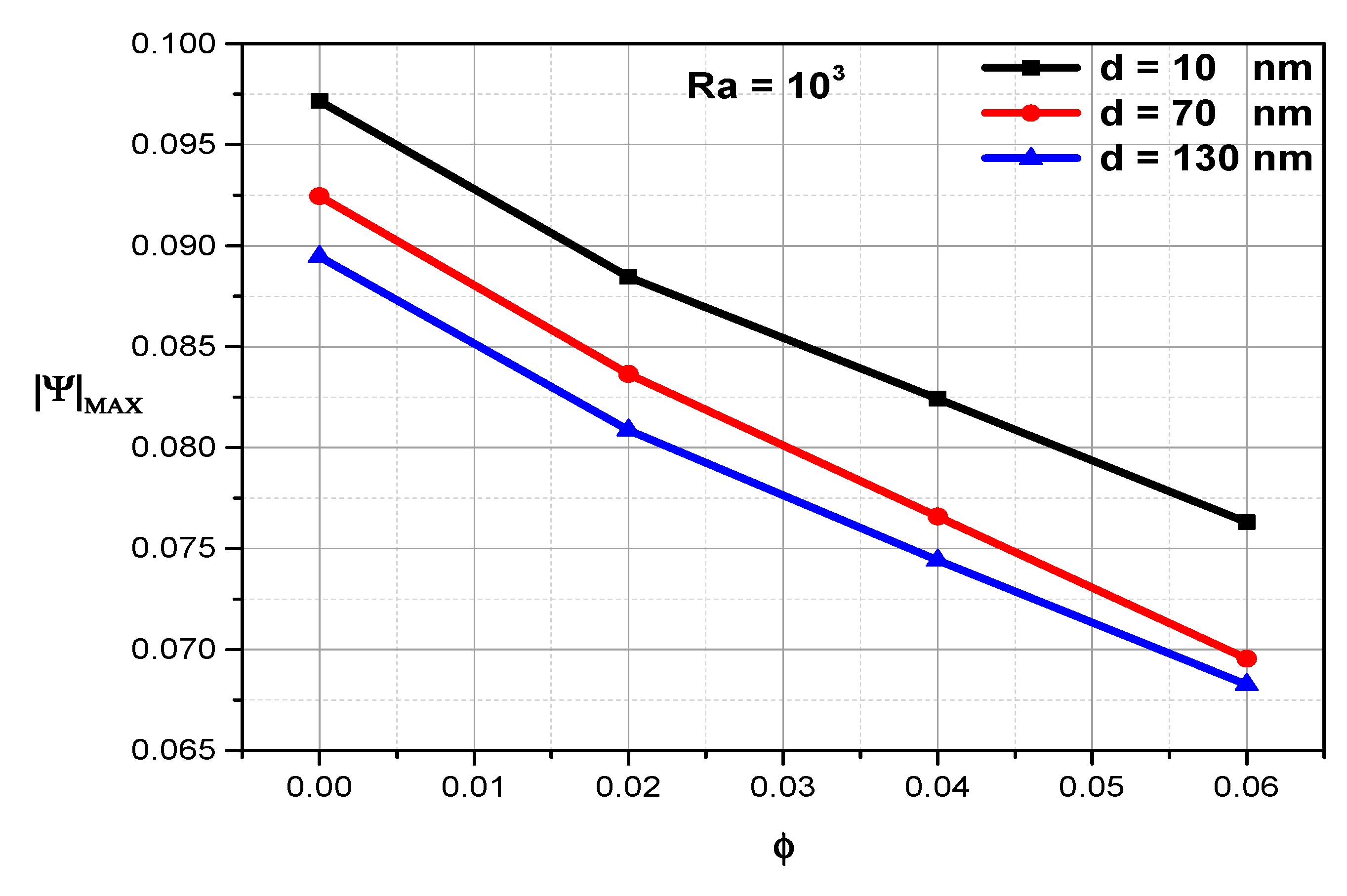
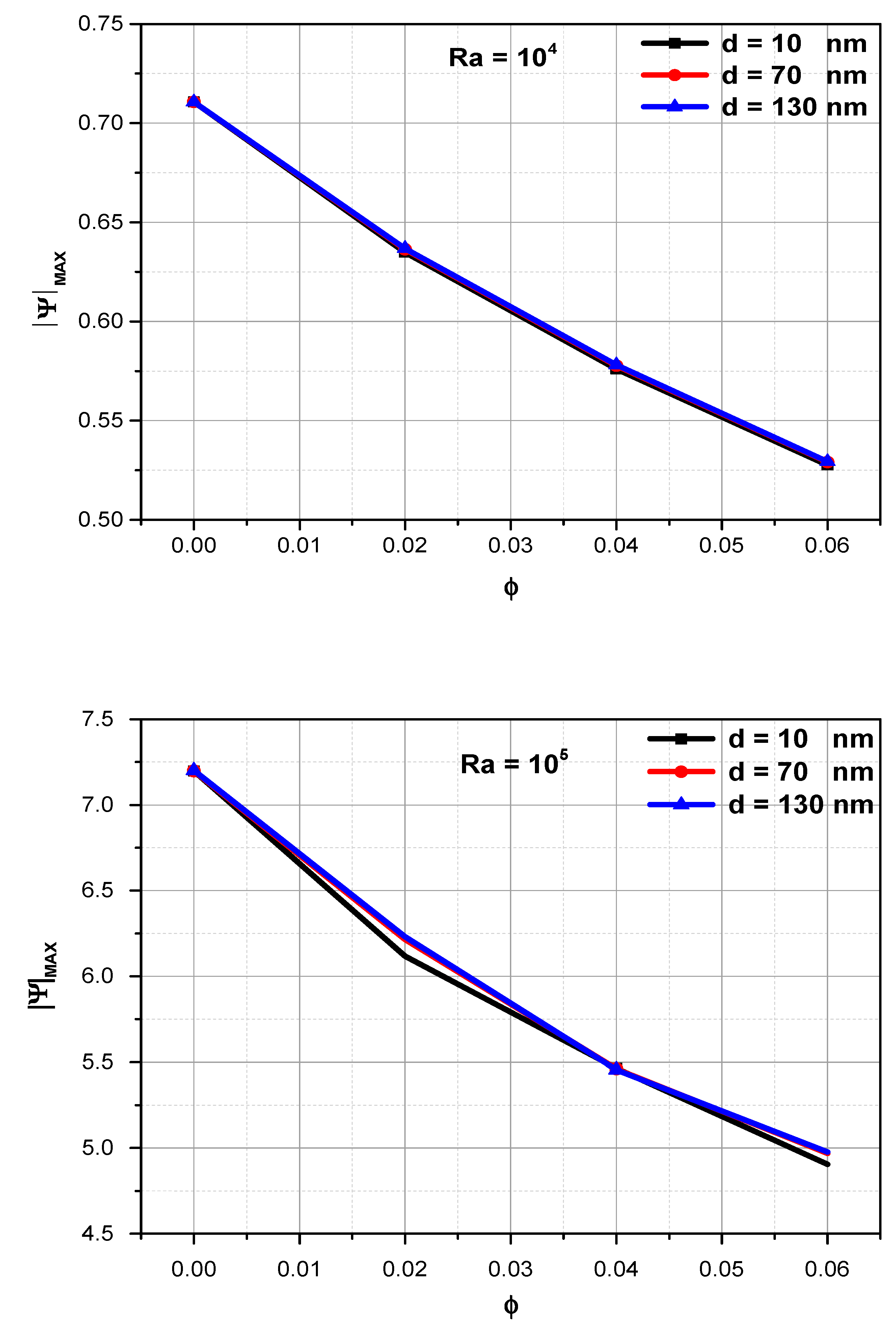
The maximum stream function decreases as (ϕ) increases, while it increases as (Ra) increases. On the other side, the effect of (dp) on the relationship between the maximum stream function and the solid volume fraction begins to decrease significantly as Ra increases from 103 to 105.
19.
The average Nusselt is directly proportional to (Ra) and (ϕ) and inversely proportional to (dp).
Finally, the physical aspect of the present study was performed by testing the effect of the magnetic field on the natural convection in a cubical cavity when the nanoparticle diameter is considered either fixed or variable from a physical engineering point of view. As future extension to this research, the influence of porous media and radiation parameter may be investigated.

Author Contributions

Conceptualization, A.K.H. and L.K.; Data curation, M.S., A.K.H. and R.Z.H.; Formal analysis, M.S., A.A., U.B. and B.A.; Funding acquisition, O.Y.; Investigation, M.S. and R.Z.H.; Methodology, A.A. and L.K.; Project administration, A.K.H., L.K. and O.Y.; Resources, O.Y.; Software, M.S.; Validation, M.S. and U.B.; Visualization, M.S.; Writing—original draft, M.S., A.K.H., A.A., R.Z.H. and U.B.; Writing—review & editing, B.A. and O.Y. All authors have read and agreed to the published version of the manuscript.

Funding

This research was funded by Deanship of scientific Research at King Khalid University in Abha, Saudi Arabia, grant number (R.G.P.2/55/43).

Institutional Review Board Statement

Not applicable.

Informed Consent Statement

Not applicable.

Data Availability Statement

The datasets generated during and/or analyzed during the current study are available from the corresponding author on reasonable request.

Acknowledgments

The authors want to express their gratitude to the Deanship of Scientific Research at King Khalid University in Abha, Saudi Arabia, for sponsoring this work via the Large Groups Project under grant number (R.G.P.2/55/43).

Conflicts of Interest

The authors declare no conflict of interest.

Nomenclature

BoMagnetic field (Tesla)
CConcentration
CCReference or low concentration (mole/m3)
CpSpecific heat at constant pressure (J/kg·K)
DBBrownian diffusion coefficient (m2/s)
DTThermal diffusion coefficient (m2/s)
dpDiameter of nanoparticle (nm)
gAcceleration due to gravity (m/s2)
HHeight or width or depth of the cavity (m)
HaHartmann number
kThermal conductivity (W/m·°C)
kBBoltzmann constant (J/K)
LeModified Lewis number
N T B T Dynamic thermo-diffusion parameter
N T B T c Dynamic diffusion parameter
NuNusselt number
NEmpirical nanoparticle shape factor
PDimensionless Pressure
pPressure (N/m2)
PrPrandtl number
RaTThermal Rayleigh number
RaCSolutal Rayleigh number
ScSchmidt number
TTemperature (K)
TCReference temperature (K)
UDimensionless velocity component in X-direction
uVelocity component in x-direction (m/s)
VDimensionless velocity component in Y-direction
vVelocity component in y-direction (m/s)
WDimensionless velocity component in Z-direction
wVelocity component in z-direction (m/s)
XDimensionless coordinate in the horizontal direction
YDimensionless coordinate in the vertical direction
ZDimensionless coordinate in the axial direction
x, y, zCartesian coordinates (m)
Greek symbols
α Thermal diffusivity (m2/s)
ρDensity (kg/m3)
β Thermal expansion coefficient (1/K)
μ Dynamic viscosity (kg/m·s)
ϕ Solid volume fraction
ψ Sphericity of the nanoparticle
ν Kinematic viscosity (m2/s)
θDimensionless temperature
Φ Dimensionless concentration
σElectrical conductivity (W/m·K)
Δ C Concentration drop (mole/m3)
Δ T Temperature drop (K)
Subscripts
avAverage
CConcentration
cCold
fFluid
hHot
nfNanofluid
npNanoparticle

References

  1. Mehryan, S.A.M.; Ghalambaz, M.; Gargari, L.S.; Hajjar, A.; Sheremet, M. Natural convection flow of a suspension containing nano-encapsulated phase change particles in an eccentric annulus. J. Energy Storage 2020, 28, 101236. [Google Scholar] [CrossRef]
  2. Hajjar, A.; Mehryan, S.; Ghalambaz, M. Time periodic natural convection heat transfer in a nano-encapsulated phase-change suspension. Int. J. Mech. Sci. 2020, 166, 105243. [Google Scholar] [CrossRef]
  3. Ghalambaz, M.; Mehryan, S.M.A.; Hajjar, A.; Veisimoradi, A. Unsteady natural convection flow of a suspension comprising Nano-Encapsulated Phase Change Materials (NEPCMs) in a porous medium. Adv. Powder Technol. 2020, 31, 954–966. [Google Scholar] [CrossRef]
  4. El-Gendi, M. Numerical simulation of unsteady natural convection flow inside a pattern of connected open square cavities. Int. J. Therm. Sci. 2018, 127, 373–383. [Google Scholar] [CrossRef]
  5. Kefayati, G. Effect of a magnetic field on natural convection in an open cavity subjugated to water/alumina nanofluid using Lattice Boltzmann method. Int. Commun. Heat Mass Transf. 2013, 40, 67–77. [Google Scholar] [CrossRef]
  6. Ghachem, K.; Kolsi, L.; Mâatki, C.; Hussein, A.K.; Borjini, M. Numerical simulation of three-dimensional double diffusive free convection flow and irreversibility studies in a solar distiller. Int. Commun. Heat Mass Transf. 2012, 39, 869–876. [Google Scholar] [CrossRef]
  7. Onyango, O.; Sigey, J.; Okelo, J.; Okwoyo, J. Enhancement of natural convection heat transfer in a square enclosure with localized heating from below. Int. J. Sci. Res. 2013, 2, 82–87. [Google Scholar]
  8. Hussein, A.K.; Lioua, K.; Chand, R.; Sivasankaran, S.; Nikbakhti, R.; Li, D.; Naceur, B.M.; Habib, B.A. Three-dimensional unsteady natural convection and entropy generation in an inclined cubical trapezoidal cavity with an isothermal bottom wall. Alex. Eng. J. 2016, 55, 741–755. [Google Scholar] [CrossRef] [Green Version]
  9. Al-Rashed, A.A.; Kolsi, L.; Hussein, A.K.; Hassen, W.; Aichouni, M.; Borjini, M.N. Numerical study of three-dimensional natural convection and entropy generation in a cubical cavity with partially active vertical walls. Case Stud. Therm. Eng. 2017, 10, 100–110. [Google Scholar] [CrossRef]
  10. Alnaqi, A.; Hussein, A.K.; Kolsi, L.; Al-Rashed, A.; Li, D.; Ali, H. Computational study of natural convection and entropy generation in 3-D cavity with active lateral walls. Therm. Sci. 2020, 24, 2089–2100. [Google Scholar] [CrossRef]
  11. Ghachem, K.; Hussein, A.K.; Kolsi, L.; Younis, O. CNT-water nanofluid magneto-convective heat transfer in a cubical cavity equipped with perforated partition. Eur. Phys. J. Plus 2021, 136, 377. [Google Scholar] [CrossRef]
  12. AbdulHussein, W.A.; Abed, A.M.; Mohammed, D.B.; Smaisim, G.F.; Baghaei, S. Investigation of boiling process of different fluids in microchannels and nanochannels in the presence of external electric field and external magnetic field using molecular dynamics simulation. Case Stud. Therm. Eng. 2022, 35, 102105. [Google Scholar] [CrossRef]
  13. Gangawane, K.M. Effect of angle of applied magnetic field on natural convection in an open ended cavity with partially active walls. Chem. Eng. Res. Des. 2017, 127, 22–34. [Google Scholar] [CrossRef]
  14. Bakier, M. Flow in open C-shaped cavities : How far does the change in boundaries affect nanofluid ? Eng. Sci. Technol. Int. J. 2014, 17, 116–130. [Google Scholar] [CrossRef] [Green Version]
  15. Ghoben, Z.; Hussein, A.K. The natural convection inside a 3D triangular cross section cavity filled with nanofluid and included cylinder with different arrangements. Diagnostyka 2022, 23, 2022205. [Google Scholar] [CrossRef]
  16. Miroshnichenko, I.V.; Sheremet, M.A.; Oztop, H.F.; Al-Salem, K. MHD natural convection in a partially open trapezoidal cavity filled with a nanofluid. Int. J. Mech. Sci. 2016, 119, 294–302. [Google Scholar] [CrossRef]
  17. Bhuvaneswari, M.; Eswaramoorthi, S.; Sivasankaran, S.; Hussein, A.K. Cross-diffusion effects on MHD mixed convection over a stretching surface in a porous medium with chemical reaction and convective condition. Eng. Trans. 2019, 67, 3–19. [Google Scholar]
  18. Zarei, M.S.; Abad, A.T.K.; Hekmatifar, M.; Toghraie, D. Heat transfer in a square cavity filled by nanofluid with sinusoidal wavy walls at different wavelengths and amplitudes. Case Stud. Therm. Eng. 2022, 34, 101970. [Google Scholar] [CrossRef]
  19. Hussein, A.K. Applications of nanotechnology in renewable energies—A comprehensive overview and understanding. Renew Sustain. Energy Rev. 2015, 42, 460–476. [Google Scholar] [CrossRef]
  20. Hussein, A.K. Applications of nanotechnology to improve the performance of solar collectors—Recent advances and overview. Renew. Sustain. Energy Rev. 2016, 62, 767–792. [Google Scholar] [CrossRef]
  21. Hussein, A.K.; Li, D.; Kolsi, L.; Kata, S.; Sahoo, B. A review of nanofluid role to improve the performance of the heat pipe solar collectors. Energy Procedia 2017, 109, 417–424. [Google Scholar] [CrossRef]
  22. Hussein, A.K.; Walunj, A.; Kolsi, L. Applications of nanotechnology to enhance the performance of the direct absorption solar collectors. J. Therm. Eng. 2016, 2, 529–540. [Google Scholar] [CrossRef]
  23. Haddad, Z.; Abid, C.; Oztop, H.F.; Mataoui, A. A review on how the researchers prepare their nanofluids. Int. J. Therm. Sci. 2014, 76, 168–189. [Google Scholar] [CrossRef]
  24. Bahiraei, M.; Hangi, M. Flow and heat transfer characteristics of magnetic nanofluids-a review. J. Magn. Magn. Mater. 2015, 374, 125–138. [Google Scholar] [CrossRef]
  25. Kamel, M.; Lezsovits, F.; Hussein, A.K. Experimental studies of flow boiling heat transfer by using nanofluids: A recent critical review. J. Therm. Anal. Calorim. 2019, 138, 4019–4043. [Google Scholar] [CrossRef] [Green Version]
  26. Kolsi, L.; Alrashed, A.A.; Al-Salem, K.; Oztop, H.F.; Borjini, M.N. Control of natural convection via an inclined plate of CNT-water nanofluid in an open-sided cubical enclosure under magnetic field. Int. J. Heat Mass Transf. 2017, 111, 1007–1018. [Google Scholar] [CrossRef]
  27. Kolsi, L.; Oztop, H.; Ghachem, K.; Al-Meshaal, M.; Mohammed, H.; Babazadeh, H.; Abu-Hamden, N. Numerical study of periodic magnetic field effect on 3D natural convection of MWCNT-water/nanofluid with consideration of aggregation. Processes 2019, 7, 957. [Google Scholar] [CrossRef] [Green Version]
  28. Kolsi, L.; Algarni, S.; Mohammed, H.A.; Hassen, W.; Lajnef, E.; Aich, W.; Almeshaal, M.A. 3D magneto-buoyancy-thermocapillary convection of CNT-water nanofluid in the presence of a magnetic field. Processes 2020, 8, 258. [Google Scholar] [CrossRef] [Green Version]
  29. Al-Rashed, A.A.; Kolsi, L.; Oztop, H.F.; Aydi, A.; Malekshah, E.H.; Abu-Hamdeh, N.; Borjini, M.N. 3D magneto-convective heat transfer in CNT-nanofluid filled cavity under partially active magnetic field. Phys. E Low-Dimens. Syst. Nanostruct. 2018, 99, 294–303. [Google Scholar] [CrossRef]
  30. Al-Rashed, A.A.; Kalidasan, K.; Kolsi, L.; Aydi, A.; Malekshah, E.H.; Hussein, A.K.; Kanna, R. Three-dimensional investigation of the effects of external magnetic field inclination on laminar natural convection heat transfer in CNT-water nanofluid filled cavity. J. Mol. Liq. 2018, 252, 454–468. [Google Scholar] [CrossRef]
  31. Sheikholeslami, M.; Ellahi, R. Three-dimensional mesoscopic simulation of magnetic field effect on natural convection of nanofluid. Int. J. Heat Mass Transf. 2015, 89, 799–808. [Google Scholar] [CrossRef]
  32. Sheikholeslami, M.; Bandpy, M.; Ashorynejad, H. Lattice Boltzmann method for simulation of magnetic field effect on hydrothermal behavior of nanofluid in a cubic cavity. Physica A 2015, 432, 58–70. [Google Scholar] [CrossRef]
  33. Uddin, M.; Alam, M.; Al-Salti, N.; Rahman, M. Investigations of natural convection heat transfer in nanofluids filled horizontal semicircular-annulus using non-homogeneous dynamic model. Am. J. Heat Mass Transf. 2016, 3, 425–452. [Google Scholar]
  34. Uddin, M.; Rahman, M.; Alam, M. Analysis of natural convective heat transport in homocentric annuli containing nanofluids with an oriented magnetic field using non-homogeneous dynamic model. Neural Comput. Appl. 2018, 30, 3189–3208. [Google Scholar] [CrossRef]
  35. Uddin, M.; Fazlul Hoque, A.; Rahman, M.; Vajravelu, K. Numerical simulation of convective heat transport within the nanofluid filled vertical tube of plain and uneven sidewalls. Int. J. Thermofluid Sci. Technol. 2019, 6, 19060101. [Google Scholar]
  36. Al-Balushi, L.; Rahman, M. Natural convective heat transfer in the presence of a sloping magnetic field inside a square enclosure with different wall temperature distributions utilizing magnetic nanoparticles following non-homogeneous dynamic model. J. Therm. Sci. Eng. Appl. 2019, 11, 041013. [Google Scholar] [CrossRef]
  37. Alhashash, A. Natural convection of nano liquid from a cylinder in square porous enclosure using Buongiorno’s two-phase model. Sci. Rep. 2020, 10, 143. [Google Scholar] [CrossRef]
  38. Sheikhzadeh, G.; Dastmalchi, M.; Khorasanizadeh, H. Effects of nanoparticles transport mechanisms on Al2O3-water nanofluid natural convection in a square enclosure. Int. J. Therm. Sci. 2019, 66, 51–62. [Google Scholar] [CrossRef]
  39. Choi, S.; Kim, S.; Lee, T.; Hahn, D. Computation of the natural convection of nanofluid in a square cavity with homogeneous and non-homogeneous models. Numer. Heat Transf. Part A 2014, 65, 287–301. [Google Scholar] [CrossRef]
  40. Alsabery, A.I.; Tayebi, T.; Chamkha, A.J.; Hashim, I. Effects of non-homogeneous nanofluid model on natural convection in a square cavity in the presence of conducting solid block and corner heater. Energies 2018, 11, 2507. [Google Scholar] [CrossRef] [Green Version]
  41. Al-Balushi, L.; Uddin, M.; Rahman, M. Natural convective heat transfer in a square enclosure utilizing magnetic nanoparticles. Propuls. Power Res. 2019, 8, 194–209. [Google Scholar] [CrossRef]
  42. Uddin, M.; Alam, M.; Rahman, M. Natural convective heat transfer flow of nanofluids inside a quarter-circular enclosure using non-homogeneous dynamic model. Arab. J. Sci. Eng. 2017, 42, 1883–1901. [Google Scholar] [CrossRef]
  43. Uddin, M.; Rahman, M. Numerical computation of natural convective heat transport within nanofluids filled semi-circular shaped enclosure using non-homogeneous dynamic model. Therm. Sci. Eng. Prog. 2017, 1, 25–38. [Google Scholar] [CrossRef]
  44. Uddin, M.; Rasel, S. Numerical analysis of natural convective heat transport of copper oxide-water nanofluid flow inside a quadrilateral vessel. Heliyon 2019, 5, e01757. [Google Scholar] [CrossRef] [Green Version]
  45. Alsabery, A.; Ayaal, A.; Hashim, I. Impacts of non-homogeneous nanofluid approach and orientation angle on convection heat transfer within a 3D wavy cavity. IOP Conf. Ser. Mater. Sci. Eng. 2020, 765, 012035. [Google Scholar]
  46. Suresh Reddy, E.; Panda, S.; Nayak, M.; Makinde, O. Crossflow on transient double-diffusive natural convection in inclined porous trapezoidal enclosures. Heat Transf.-Asian Res. 2021, 50, 849–875. [Google Scholar]
  47. Ushachew, E.; Sharma, M.; Makinde, O. Heat convection in micropolar nanofluid through porous medium-filled rectangular open enclosure: Effect of an embedded heated object with different geometries. Therm. Anal. Calorim. 2021, 146, 1865–1881. [Google Scholar] [CrossRef]
  48. Khan, Z.; Makinde, O.; Hamid, M.; Haq, R.; Khan, A. Hydromagnetic flow of ferrofluid in an enclosed partially heated trapezoidal cavity filled with a porous medium. J. Magn. Magn. Mater. 2020, 499, 166241. [Google Scholar] [CrossRef]
  49. Girish, N.; Sankar, M.; Makinde, O. Developing buoyant convection in vertical porous annuli with unheated entry and exit. Heat Transf.-Asian Res. 2020, 49, 2551–2576. [Google Scholar]
  50. Hussain, S.; Hussein, A.K. Natural convection heat transfer enhancement in a differentially heated parallelogrammic enclosure filled with copper-water nanofluid. J. Heat Transf.-Trans. ASME 2014, 136, 082502. [Google Scholar] [CrossRef]
  51. Hussein, A.K.; Hussain, S. Heatline visualization of natural convection heat transfer in an inclined wavy cavities filled with nanofluids and subjected to a discrete isoflux heating from its left sidewall. Alex. Eng. J. 2016, 55, 169–186. [Google Scholar] [CrossRef] [Green Version]
  52. Hussein, A.K.; Mustafa, A. Natural convection in fully open parallelogrammic cavity filled with Cu-water nanofluid and heated locally from its bottom wall. Therm. Sci. Eng. Prog. 2017, 1, 66–77. [Google Scholar] [CrossRef]
  53. Hussein, A.K.; Bakier, M.; Ben Hamida, M.; Sivasankaran, S. Magneto-hydrodynamic natural convection in an inclined T-shaped enclosure for different nanofluids and subjected to a uniform heat source. Alex. Eng. J. 2016, 55, 2157–2169. [Google Scholar] [CrossRef] [Green Version]
  54. Ghasemi, B.; Aminossadati, S.; Raisi, A. Magnetic field effect on natural convection in a nanofluid-filled square enclosure. Int. J. Therm. Sci. 2011, 50, 1748–1756. [Google Scholar] [CrossRef]
  55. Al-Farhany, K.; Abdulkadhim, A.; Hamzah, H.K.; Ali, F.H.; Chamkha, A. MHD effects on natural convection in a U-shaped enclosure filled with nanofluid-saturated porous media with two baffles. Prog. Nucl. Energy 2022, 145, 104136. [Google Scholar] [CrossRef]
Figure 1. Physical domain (a) and the mesh generation (b) of the considered problem.
Mathematics 10 02072 g001
Figure 2. Comparison of y-velocity (left) and temperature (right) along the mid-span of a two–dimensional cavity between the present work and (Ghasemi et al., 2018 for various values of Hartmann and Rayleigh numbers at (ϕ = 0.03).
Mathematics 10 02072 g002
Figure 3. Comparison of isotherms between the present work and Ghasemi et al. [54] for various values of Hartmann and Rayleigh numbers at (ϕ = 0.03).
Mathematics 10 02072 g003aMathematics 10 02072 g003b
Figure 4. Flow (top) and thermal (bottom) structures inside the cavity for various values of the Hartmann number at [ϕ = 0 (solid line), ϕ = 0.04 (dash line) and Ra = 105] and (dp = 10 nm).
Mathematics 10 02072 g004
Figure 5. The variation of the temperature distribution along the X-axis for different Rayleigh numbers, Hartmann numbers, and the solid volume fractions at (dp = 10 nm).
Mathematics 10 02072 g005aMathematics 10 02072 g005b
Figure 6. The variation of the velocity profiles along the X-axis (left) and Y-axis (right) for different Rayleigh numbers, Hartmann numbers, and the solid volume fractions at (dp = 10 nm).
Mathematics 10 02072 g006aMathematics 10 02072 g006b
Figure 7. The variation of the local Nusselt number along the vertical axis for various values of the Rayleigh and Hartmann numbers at (dp = 10 nm and ϕ = 0.02).
Mathematics 10 02072 g007aMathematics 10 02072 g007b
Figure 8. The variation between the average Nusselt number and the solid volume fraction for various values of the Rayleigh number at (dp = 10 nm).
Mathematics 10 02072 g008aMathematics 10 02072 g008b
Figure 9. Flow structures inside the cavity for various values of Rayleigh number and diameter of nanoparticle at [ϕ = 0 (solid line), ϕ = 0.04 (dash line)] and Ha = 30.
Mathematics 10 02072 g009
Figure 10. Variation of the temperature profiles on the Y-axis for different Rayleigh numbers and nanoparticle diameters at (Ha = 30 and ϕ = 0.04).
Mathematics 10 02072 g010aMathematics 10 02072 g010b
Figure 11. The variation between the stream function and the solid volume fraction for various values of the Rayleigh number and nanoparticle diameter at (Ha = 30).
Mathematics 10 02072 g011aMathematics 10 02072 g011b
Figure 12. Variation of the velocity profiles on the Y-axis for different Rayleigh numbers and nanoparticle diameters at (Ha = 30 and ϕ = 0.04).
Mathematics 10 02072 g012aMathematics 10 02072 g012b
Figure 13. The variation between the average Nusselt number and the solid volume fraction for various values of the Rayleigh number and nanoparticle diameter at (Ha = 30).
Mathematics 10 02072 g013aMathematics 10 02072 g013b
Table 1. Thermo-physical characteristics of pure water and nanoparticles [50].
ρ (kg·m−3)β (K−1)k (W·m−1·K−1)Cp (J·kg−1·K−1)
Pure Water997.121 × 10−50.6134179
Cu89331.67 × 10−5400385
Table 2. Sensitivity to the mesh of the average Nusselt number at different numbers of grids for (Ra = 105, ϕ = 0.02 and d = 1).
41 × 41 × 4151 × 51 × 5161 × 61 × 6171 × 71 × 7181 × 81 × 81
Nuav5.7486855.7215635.6984855.6952355.692066
Publisher’s Note: MDPI stays neutral with regard to jurisdictional claims in published maps and institutional affiliations.

