
Optimum Design of Reinforced Concrete Folded Plate Structures to ACI 318-11 Using Soft Computing Algorithm


Abstract
:1. Introduction
2. Materials and Methods
2.1. Mathematical Modeling
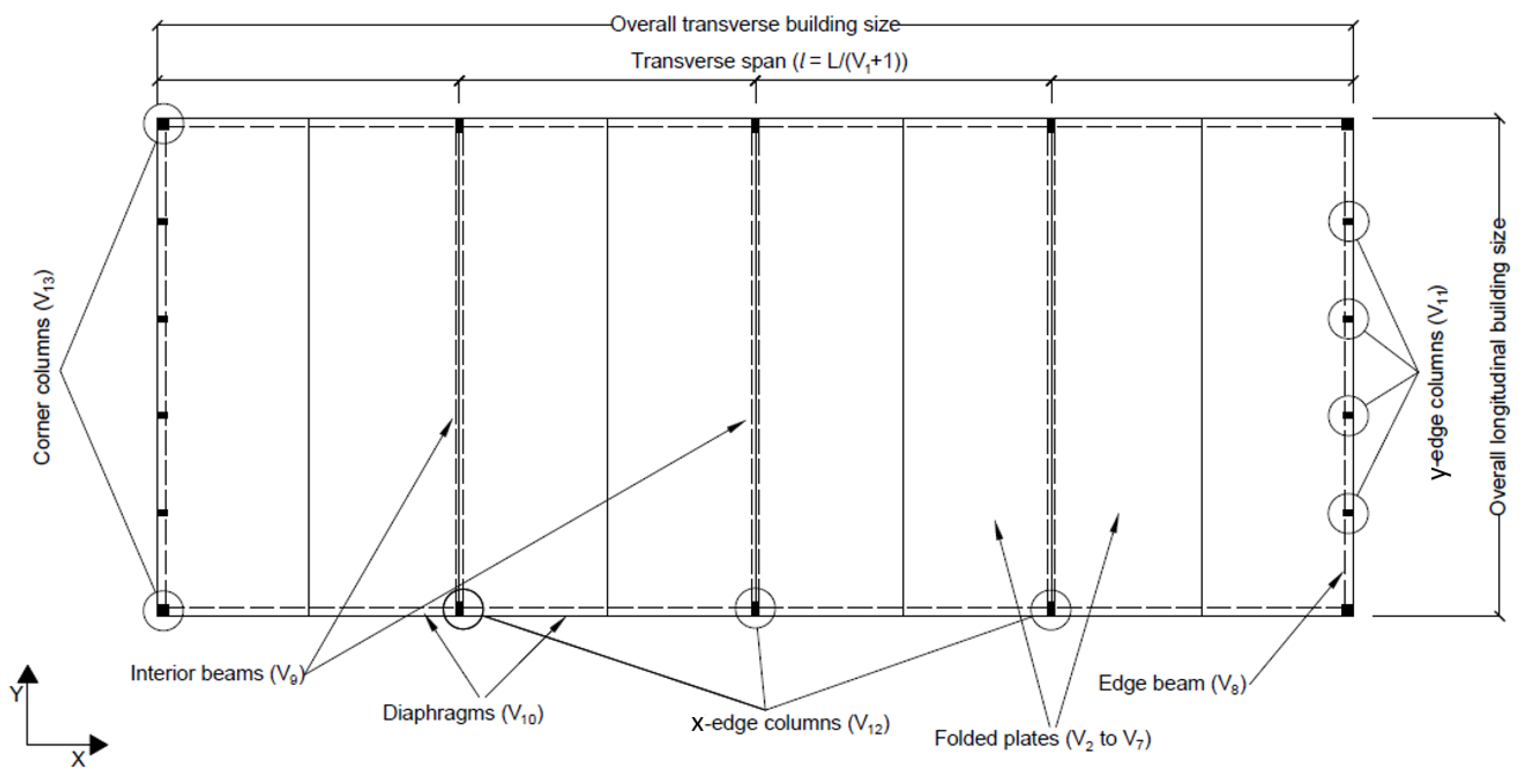
2.1.1. Design Variables
Folded Plate Variables
Auxiliary Members’ Variables
Supporting Columns Variables
Variable Pool
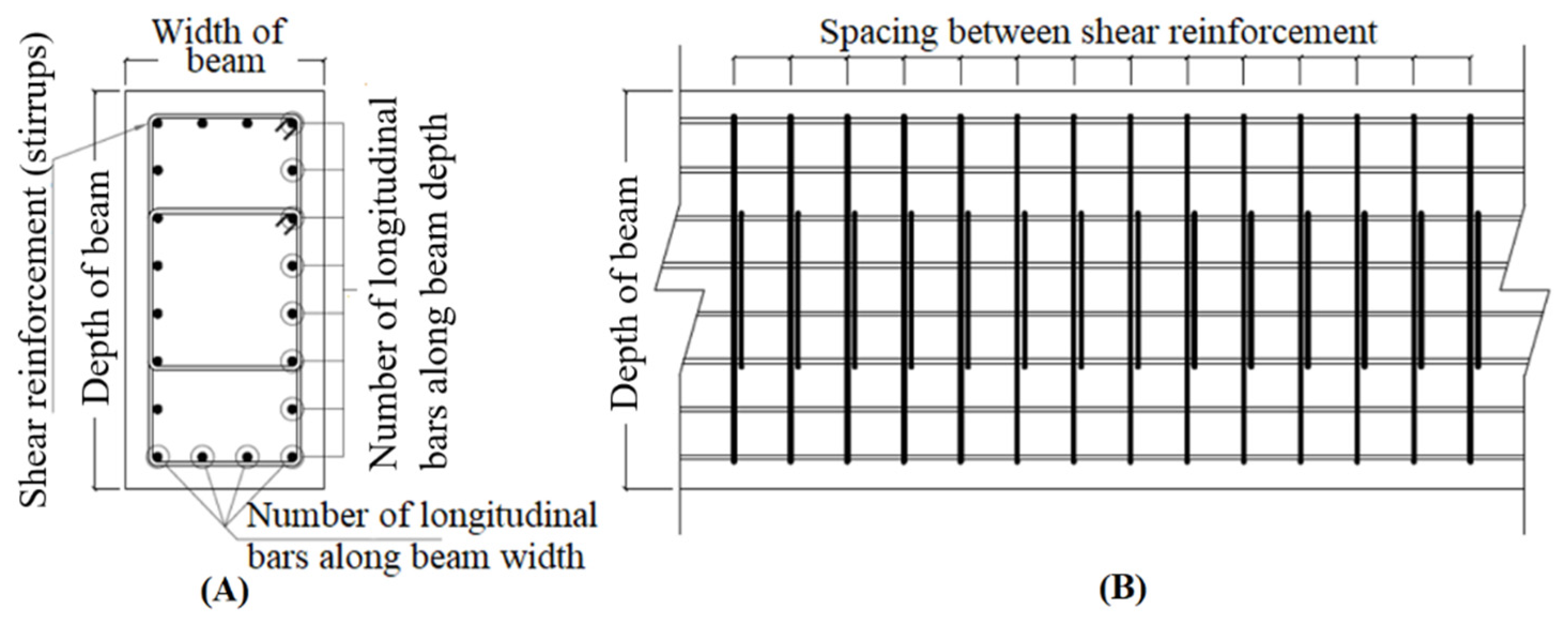
2.1.2. Objective Function
2.1.3. Design Constraints
Plate Constraints
Auxiliary Members’ Constraints
Column’s Constraints
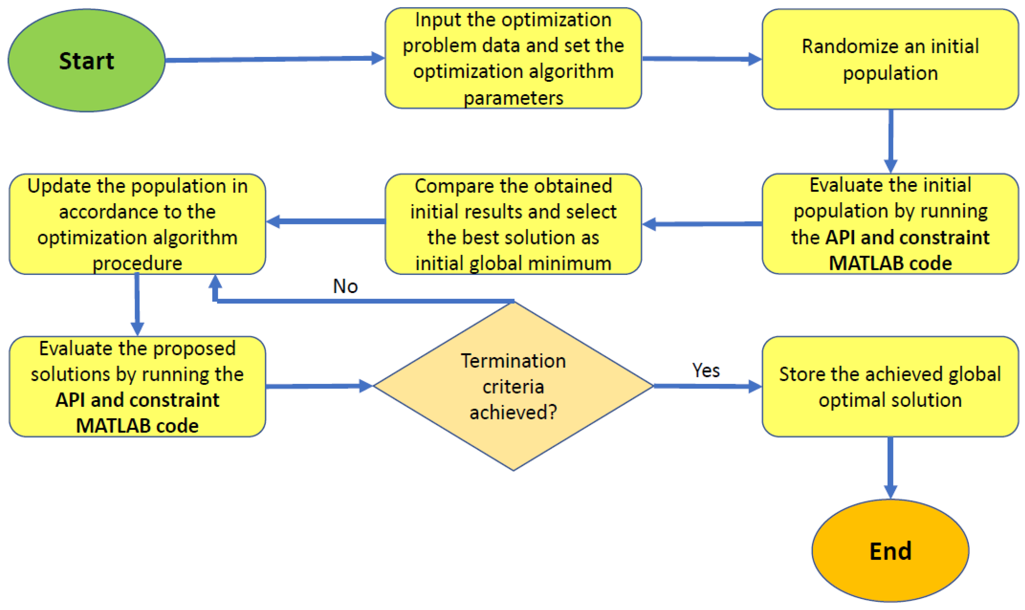
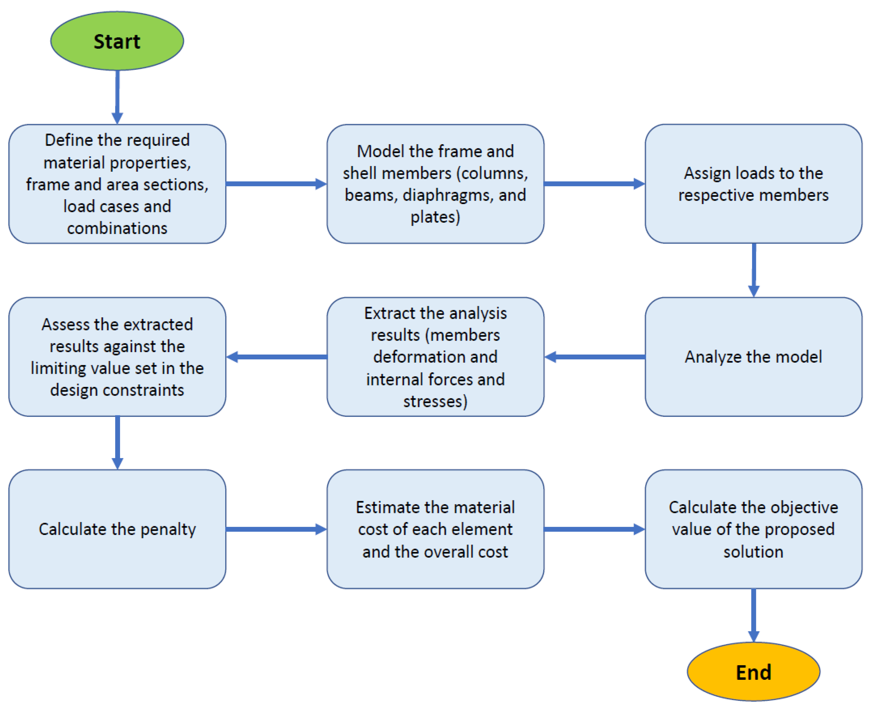
2.2. Soft Computing Techniques
2.2.1. Artificial Bee Colony (ABC) Algorithm
2.2.2. Differential Evolution (DE) Algorithm
- 1.
- Initial population is generated randomly in the search space which consists of m number of agents x, each of which comprises n design variables.
- 2.
- For each agent xj where j = 1,…, n the following is carried out:
- Three agents xa, xb, and xc which are distinctly different from each other and that of xj are selected randomly from the population.
- Index k, which is between 1 to n is selected randomly.
- The agent’s trial vector xt is computed by iterating over each as follows:
- ❖
- Select a random number ri ~
- ❖
- Compute the trial vector as if i = k or ri ≤ CR otherwise xt = xj where CR is the crossover rate and F is the scaling (weighting) factor defined by users.
- The trial vector is updated considering the lower and upper bound vectors as if , if . If then xt is replaced by the agent xj.
- 3.
- The agent xo from the population having the lowest fitness is the best-found solution within this generation.
- 4.
- Continue the generation until stopping criteria is satisfied.
2.2.3. Beetle Antennae Search (BAS) Algorithm
2.2.4. Population Based Beetle Antenna Search (pbBAS) Algorithm
3. Results
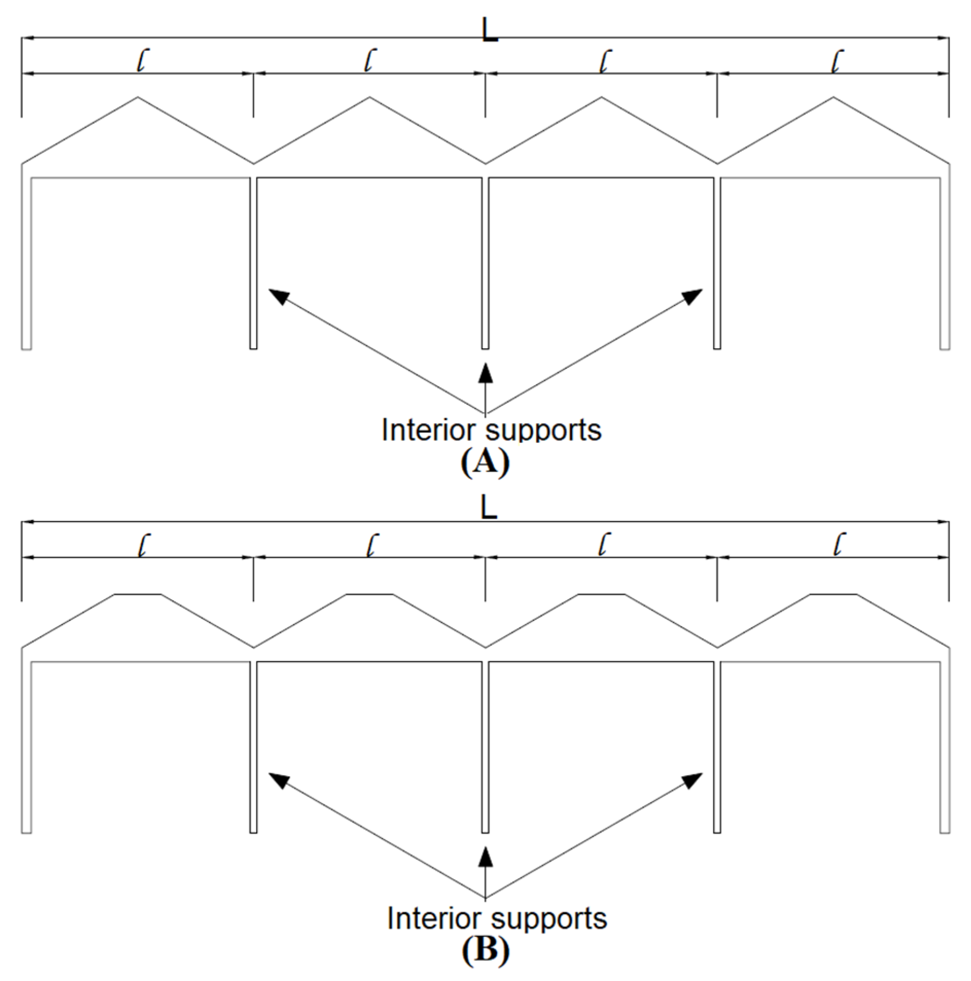
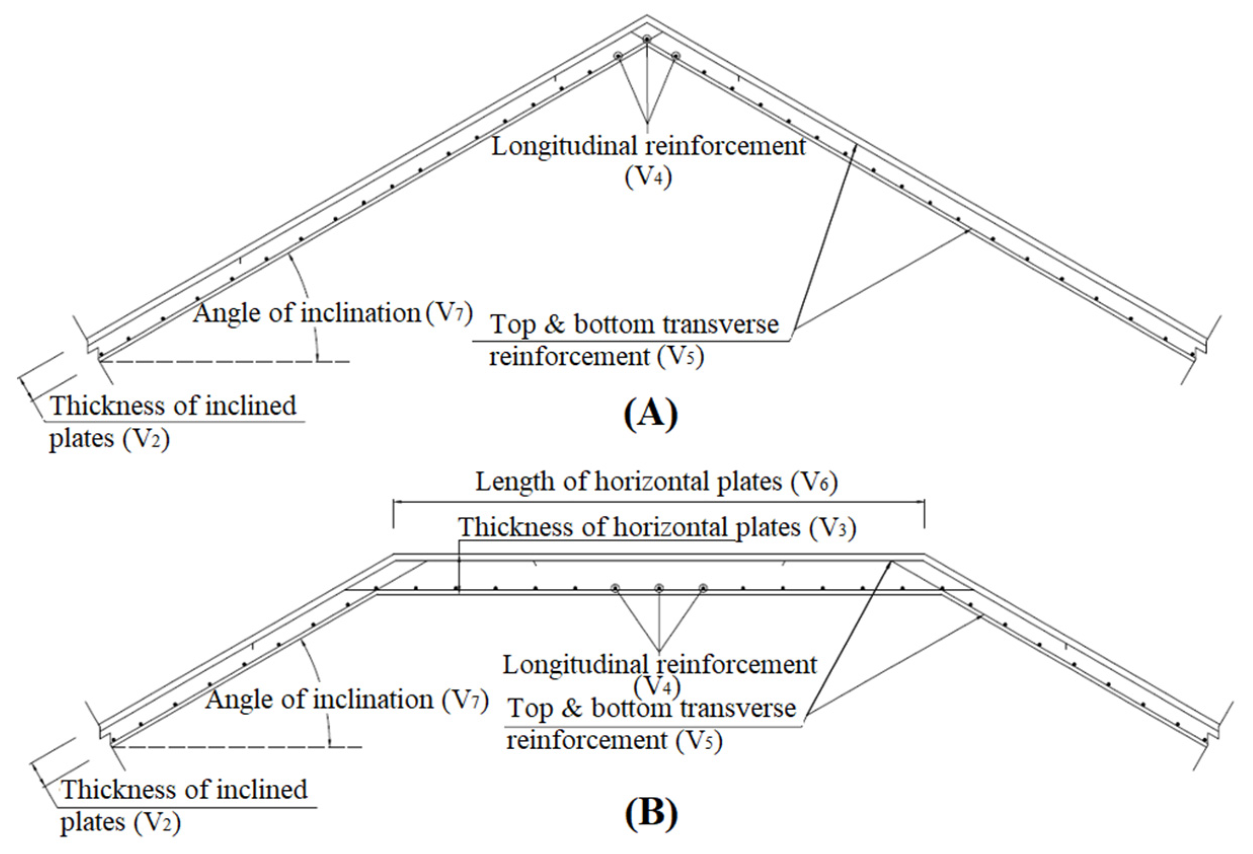
3.1. V-Type Folded Plate Roof Problem
3.2. Three-Segment Type Folded Plate Roof Problem
4. Discussion
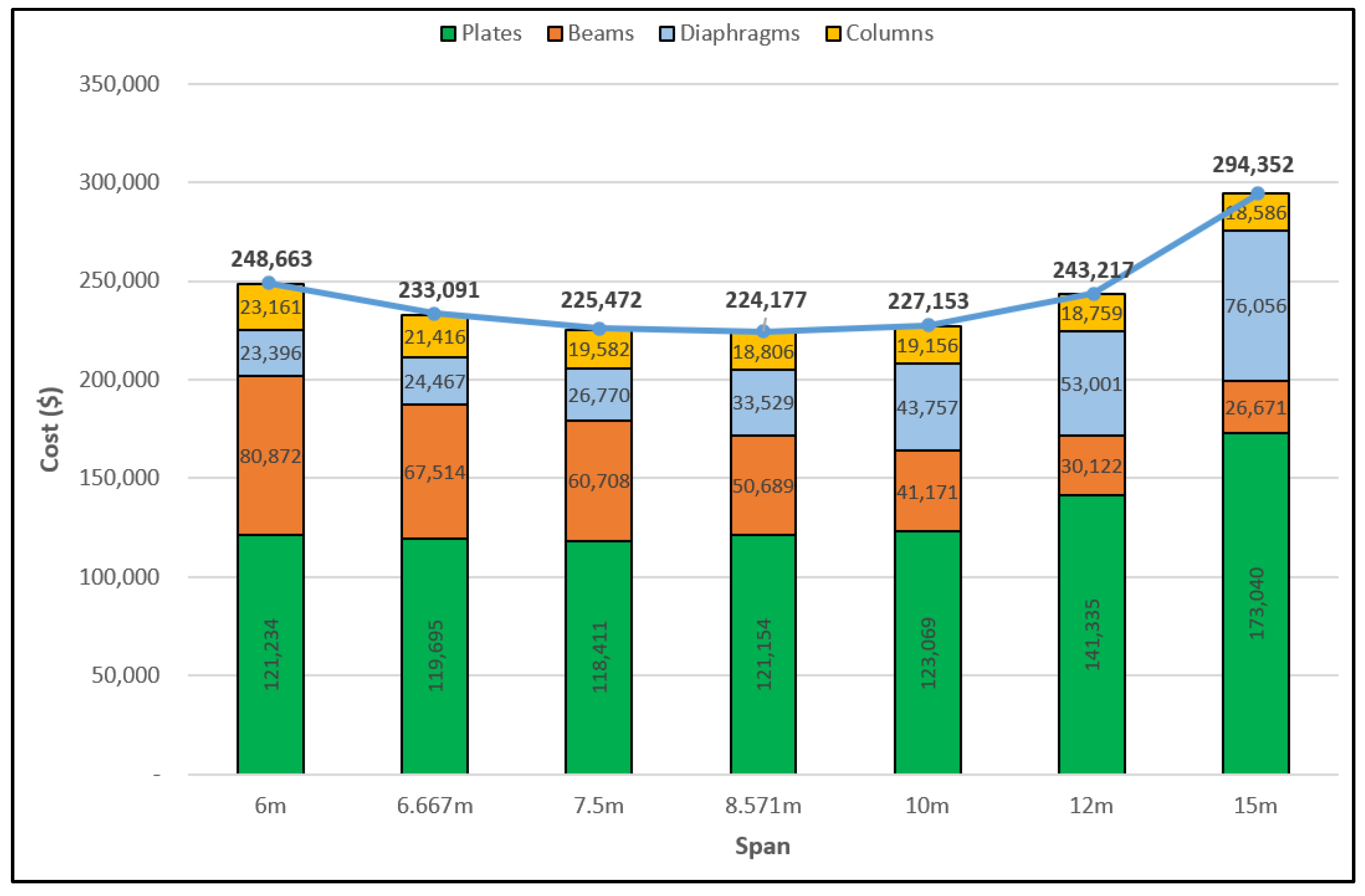
4.1. V-Type Folded Plate Roof Problem
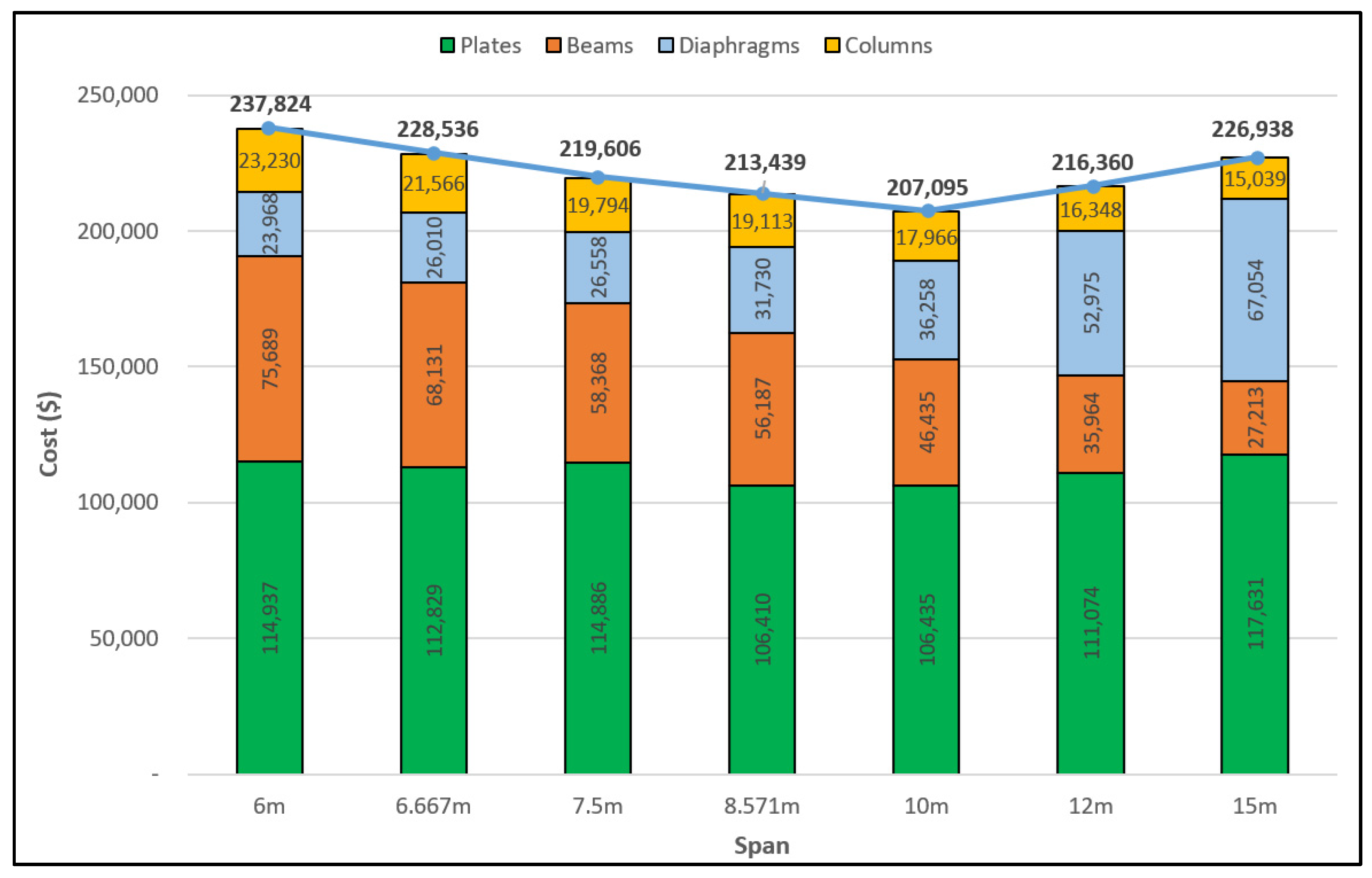
4.2. Three-Segment Type Folded Plate Roof Problem
5. Conclusions
Author Contributions
Funding
Institutional Review Board Statement
Informed Consent Statement
Data Availability Statement
Conflicts of Interest
References
- Bar-Yoseph, P.; Hersckovitz, I. Analysis of folded plate structures. Thin-Walled Struct. 1989, 7, 139–158. [Google Scholar] [CrossRef]
- Wilby, C.B. Concrete Folded Plate Roofs; Elsevier-Butterworth-Heinemann: Oxford, UK, 2005; ISBN 0-340-66266-2. [Google Scholar]
- Varghese, P.C. Design of Reinforced Concrete Shells and Folded Plates; PHI Learning Private Ltd.: New Delhi, India, 2010; ISBN 978-81-203-4111-1. [Google Scholar]
- Gomez, R.A. Design of Folded Plates, PDH Online Course S275 (5PDH), PDH Center. 2013. Available online: https://pdhonline.com/courses/s275/s275content.pdf (accessed on 14 April 2022).
- Sarma, K.C.; Adeli, H. Cost optimization of concrete structures. J. Struct. Eng. 1998, 124, 570–578. [Google Scholar] [CrossRef]
- Kostem, C.N. Optimization of folded plate roofs. Comput. Struct. 1973, 3, 125–132. [Google Scholar] [CrossRef]
- ACI 318-11; Building Code Requirements for Structural Concrete and Commentary. American Concrete Institute Committee: Farmington Hills, MI, USA, 2011; ISBN 978-0-87031-744-6.
- ACI.318.2-14; Building Code Requirements for Concrete Thin Shells and Commentary. American Concrete Institute Committee: Farmington Hills, MI, USA, 2014; ISBN 978-0-87031-934-1.
- Mathworks. Available online: https://www.mathworks.com/products/matlab.html (accessed on 25 April 2021).
- Computers & Structures, Inc. Available online: https://www.csiamerica.com/products/sap2000 (accessed on 25 April 2021).
- ASCE/SEI 7-05; Minimum Design Loads for Buildings and Other Structures. American Society of Civil Engineers: Farmington Hills, MI, USA, 2005; ISBN 0-7844-0831-9.
- Kaveh, A. Advances in Metaheuristic Algorithms for Optimal Design of Structures; Springer: Berlin/Heidelberg, Germany, 2017. [Google Scholar] [CrossRef]
- Latif, M.A.; Saka, M.P. Optimum design of tied-arch bridges under code requirements using enhanced artificial bee colony algorithm. Adv. Eng. Softw. 2019, 135, 102685. [Google Scholar] [CrossRef]
- Yousif, S.; Saka, M.P. Optimum design of post-tensioned flat slabs with its columns to ACI 318-11 using population-based beetle antenna search algorithm. Comput. Struct. Int. J. 2021, 256, 106520. [Google Scholar] [CrossRef]
- Wang, Z.; Tang, H.; Li, P. Optimum design of truss structures based on differential evolution strategy. In Proceedings of the International Conference on Information Engineering and Computer Science, Wuhan, China, 1–5 December 2009. [Google Scholar] [CrossRef]
- Saka, M.P.; Geem, Z.W. Mathematical and metaheuristic applications in design optimization of steel frame structures: An extensive review. Math. Probl. Eng. 2012, 2013, 271031. [Google Scholar] [CrossRef] [Green Version]
- Saka, M.P. Design code optimization of steel structures using adaptive harmony search algorithm. In Harmony Search Algorithms for Structural Design Optimization; Series: Studies in Computational Intelligence; Geem, Z.W., Ed.; Springer: Berlin/Heidelberg, Germany, 2009; Volume 239. [Google Scholar] [CrossRef]
- Saka, M.P.; Dogan, E.; Aydogdu, I. Review and analysis of swarm-intelligence based algorithms. In Swarm Intelligence and Bio-Inspired Computation; Yang, X.S., Cui, Z., Xiao, R., Gandomi, A.H., Karamanoglu, M., Eds.; Elsevier: Amsterdam, The Netherlands, 2013; pp. 25–47. [Google Scholar] [CrossRef]
- Kaveh, A.; Ghazaan, M.A.I. Metaheuristic Algorithms for Optimal Design of Real-Size Structures; Springer: Berlin/Heidelberg, Germany, 2018. [Google Scholar] [CrossRef]
- Kaveh, A.; Eslamlu, A.D. Metaheuristic Optimization Algorithms in Civil Engineering: New Applications; Springer: Berlin/Heidelberg, Germany, 2017. [Google Scholar] [CrossRef]
- Jiang, X.; Li, S. BAS: Beetle Antennae Search Algorithm for Optimization Problems. Int. J. Robot. Control. 2018, 1, 1. [Google Scholar] [CrossRef]
- Yousif, S.; Saka, M.P. Enhanced beetle antenna search: A swarm intelligence algorithm. Asian J. Civ. Eng. 2021, 22, 73–91. [Google Scholar] [CrossRef]
- Karaboga, D. An Idea Based on Honeybee Swarm for Numerical Optimization Technical Report-TR06; Computer Engineering Department, Engineering Faculty, Erciyes University: Kayseri, Turkey, 2005. [Google Scholar]
- Karaboga, D.; Basturk, B. A powerful and efficient algorithm for numerical function optimization: Artificial bee colony (ABC) algorithm. J. Glob. Optim. 2007, 39, 459–471. [Google Scholar] [CrossRef]
- Karaboga, D.; Basturk, B. On the performance of artificial bee colony (ABC) algorithm. Appl. Soft Comput. 2008, 8, 687–697. [Google Scholar] [CrossRef]
- Karaboga, D.; Akay, B. A modified artificial bee colony (ABC) algorithm for constrained optimization problems. Appl. Soft Comput. 2011, 11, 3021–3031. [Google Scholar] [CrossRef]
- Storn, R.; Price, K. Differential evolution- A simple and efficient heuristic for global optimization over continuous spaces. J. Glob. Optim. 1997, 11, 341–359. [Google Scholar] [CrossRef]


| Design Variables | Description | List of Details Grouped in the Design Variable | Number of Variables in Problem | |
|---|---|---|---|---|
| 1 | 2 | |||
| V1 | Number of internal intermediate supports | No grouping | 1 | 1 |
| V2 & V3 | Plate thickness I | No grouping | 1 | 2 |
| V4 & V5 | Plate’s reinforcement configuration in each direction II | Two grouped details:
| 2 | 2 |
| V6 | Length of horizontal plate III | No grouping | 0 | 1 |
| V7 | Angle of plate’s inclination IV | No grouping | 1 | 1 |
| V8 & V9 | Beams sectional details V | Seven grouped details:
| 2 | 2 |
| V10 | Diaphragm sectional details VI | Seven grouped details:
| 1 | 1 |
| V11–V13 | Columns sectional details VII | Seven grouped details:
| 3 | 3 |
| Total | 11 | 13 | ||
| Details | Pool | ||
|---|---|---|---|
| Number of interior supports (Nos.) | 3:1:9 | ||
| Thickness (mm) | 70:10:200 | ||
| Longitudinal and Transverse reinforcement | Diameter (mm) | {8, 10, 12, 16, 20} | |
| Spacing (mm) | For 8 mm diameter | {200, 250, 300} | |
| For 10 mm diameter | {200, 250} | ||
| For 12 mm diameter | {150, 200, 250} | ||
| For 16 mm diameter | {150, 200} | ||
| For 20 mm diameter | {100, 150, 200} | ||
| Angle of plates inclination (for inclined plates measured from the horizontal axis in degrees) | 5:1:40 | ||
| Length of horizontal plates (mm) | 500:500:5000 | ||
| Details | Pool | |||
|---|---|---|---|---|
| Size | Depth (mm) | 500:100:1200 | ||
| Width (mm) | For depth of 500 mm | {200} | ||
| For depth of 600 mm | {200, 250} | |||
| For depth of 700 mm | {250, 300} | |||
| For depth of 800 mm | {300, 350} | |||
| For depth of 900 mm | {350} | |||
| For depth of 1000 mm | {350, 400} | |||
| For depth of 1100 mm and 1200 mm | {400} | |||
| Longitudinal reinforcement | Diameter (mm) | For 200 × 500 beams | {12, 16} | |
| For 200 × 600 beams | {16, 20} | |||
| For 250 × 600 beams | {20} | |||
| For 250 × 700 beams | {16, 20} | |||
| For 300 × 700 beams | {20} | |||
| For 300 × 800 or larger beams | {20, 25} | |||
| Number of bars along (Nos.) | Minor axis | For 200 mm wide | {2} | |
| For 250 mm and 300 mm width | {3} | |||
| For 350 mm and 400 mm width | {4} | |||
| Major axis | For 500 mm depth | {5, 6} | ||
| For 600 mm depth | {5, 6, 7} | |||
| For 700 mm depth | {6, 7, 8} | |||
| For 800 mm depth | {7, 8, 9} | |||
| For 900 mm depth | {8, 9, 10} | |||
| For 1000 mm depth | {9, 10, 11} | |||
| For 1100 mm and 1200 mm depth | {10, 11, 12} | |||
| Shear reinforcement | Diameter (mm) | {8, 10, 12} | ||
| Spacing (mm) | For 8 mm diameter | {250, 300} | ||
| For 10 mm diameter | {200, 250} | |||
| For 12 mm diameter | {100, 150, 200} | |||
| Details | Pool | ||
|---|---|---|---|
| Size | Depth below inclined plates bottom level (mm) | 500:100:1000 | |
| Thickness (mm) | For depth of 500 mm | {200, 250} | |
| For depth of 600 mm | {250, 300} | ||
| For depth of 700 mm | {300, 350} | ||
| For depth of 800 mm | {350} | ||
| For depth of 900 mm | {350, 400} | ||
| For depth of 1000 mm | {400} | ||
| Horizontal (longitudinal) reinforcement | Diameter (mm) | For 200 mm thickness | {12, 16} |
| For 250 mm and 300 mm thickness | {16, 20} | ||
| For 350 mm thickness | {20, 25} | ||
| For 400 mm thickness | {25} | ||
| Number of bars along minor axis (Nos.) | For 200 mm thickness | {2} | |
| For 250 mm thickness | {2, 3} | ||
| For 300 mm thickness | {3} | ||
| For 350 mm thickness | {4} | ||
| For 400 mm thickness | {5} | ||
| Spacing along Major axis (mm) | {100, 150, 200} | ||
| Vertical (transverse) reinforcement | Diameter (mm) | {10, 12, 16} | |
| Spacing (mm) | For 10 mm diameter | {250, 300} | |
| For 12 mm diameter | {200, 250} | ||
| For 16 mm diameter | {100, 150, 200} | ||
| Details | Pool | |||
|---|---|---|---|---|
| Size | x-edge columns | Along x-direction (mm) | 400:100:700 | |
| Along y-direction (mm) | For 400 mm and 500 mm depths | {200} | ||
| For 600 mm depths | {250, 300} | |||
| For 700 mm depths | {300} | |||
| y-edge columns | Along y-direction (mm) | 400:100:700 | ||
| Along x-direction (mm) | For 400 mm and 500 mm deep | {200} | ||
| For 600 mm depths | {250, 300} | |||
| For 700 mm depths | {300} | |||
| Corner columns | Both directions (mm) | {400, 450, 500} | ||
| Longitudinal reinforcement | Diameter (mm) | x and y-edge columns | For 200 mm widths | {12, 16} |
| For 250 mm widths | {16, 20} | |||
| For 300 mm widths | {20, 25} | |||
| Corner columns | {16, 20} | |||
| x and y-edge columns number of bars along | minor axis (Nos.) | For 200 mm and 250 mm widths | {2} | |
| For 300 mm widths | {3} | |||
| Major axis (Nos.) | For 400 mm depths | {4} | ||
| For 500 mm depths | {5} | |||
| For 600 mm depths | {6} | |||
| For 700 mm depths | {7} | |||
| Corner columns number of bars along both directions (Nos.) | For 400 mm sizes | {4} | ||
| For 450 mm and 500 mm sizes | {4, 5} | |||
| Shear reinforcement | Diameter (mm) | {8, 10, 12} | ||
| Spacing (mm) | For 8 mm diameter | {200, 250, 300} | ||
| For 10 mm diameter | {150, 200, 250} | |||
| For 12 mm diameter | {100, 150, 200} | |||
| Element | Equation | Terms Definition |
|---|---|---|
| Penalized Objective function | Ctotal: total cost of materials (actual objective function). Penalty: the value of constraints violation. ε: penalty exponent (taken as 1 for all algorithms) | |
| Penalty | nc: total number of constraints. gi: ith constraint violation value. | |
| Overall cost | Cc: total cost of concrete. Cfw: total cost of formwork. Crs: total cost of reinforcing steel. | |
| Concrete | Uc: unit cost of concrete. Vcp: volume of plates concrete. Vcb: volume of beams concrete. Vcd: volume of diaphragms concrete. Vcc: volume of columns concrete. | |
| Formwork | Ufwh: unit cost of horizontal and vertical formworks. Ufwi: unit cost of inclined formworks. Afwhp: area of horizontal plates formworks. Afwip: area of inclined plates formworks. Afwb: area of beams formworks. Afwd: area of diaphragms formworks. Afwc: area of columns formworks. | |
| Reinforcement | Urs: unit cost of reinforcing steel. Wrsp: total weight of reinforcement used in plates. Wrsb: total weight of reinforcement used in beams. Wrsd: total weight of reinforcement used in diaphragms. Wrsc: total weight of reinforcement used in columns. |
| Const. | Description | Constraint Equation | Term’s Definition | Remarks |
|---|---|---|---|---|
| Membrane compression | fc(actual): plates ultimate compressive stress. fc(allowable): compression stress capacity. Ø: compression strength reduction factor (0.65). fcu: ultimate compressive strength of concrete. | |||
| Membrane tension | ft(actual): plates ultimate tensile stress. ft(allowable): tension stress capacity. Ø: tensile strength reduction factor (0.9). fy: reinforcement yield strength. As: area of reinforcement. | |||
| Transverse bending moment | Mu: ultimate transverse bending moment. Mn: nominal bending moment capacity. Ø: bending moment capacity reduction factor (ranges between 0.65 to 0.9). | ACI318-11 Clause 18.7 | ||
| Transverse shear | Vu: ultimate transverse shear force at plates interface. Vc: shear capacity of plate section. Ø: shear strength reduction factor (0.75). | ACI318-11 Clause 11.11 | ||
| Immediate deflection | δi(actual): actual immediate deflection. δi(allowable): immediate deflection limiting value. l: minimum span of plates. | |||
| Long-term deflection | δu(actual): actual long-term deflection. δu(allowable): long-term deflection limiting value. | |||
| Maximum reinforcement spacing | S(Provided): provided reinforcement spacing. S(max): maximum allowed reinforcement spacing. | Otherwise: | ||
| Minimum thickness | h: actual plates thickness. h(min): minimum allowed plate thickness. Øt: diameter of transverse reinforcement. Øl: diameter of longitudinal reinforcement. Cb: bottom face cover (15 mm). Ct: top face cover (25 mm). | |||
| Minimum reinforcement area | As: provided area of reinforcement. As(min): minimum allowable area of reinforcement. b: width of plate strip. | |||
| Maximum reinforcement area | As(max): maximum allowable area of reinforcement. |
| Const. | Description | Constraint Equation | Terms Definition | Remarks |
|---|---|---|---|---|
| Flexural strength | (1) Axial capacity: (2) Moment capacity: (3) Combined flexural capacity: | Pu: ultimate axial load acting on the section. Mu: ultimate bending moment acting on the section. Pn: axial force capacity of the section under the given ultimate loads. Mn: bending moment capacity of the section under the given ultimate loads. Ø: capacity reduction factor (ranges between 0.65 to 0.9). b: perpendicular section dimension to the bending moment. h: parallel section dimension to the bending moment. | According to the interaction diagram shown in Figure 7. | |
| Shear strength | Vu: ultimate shear force acting on the section. Vc: shear capacity of the section. Ø: shear strength reduction factor (0.75). | ACI318-11 Clause 11.11 | ||
| Minimum reinforcement spacing | S(provided): provided reinforcement spacing. S(min): minimum allowed reinforcement spacing for the section. | = 40 mm | ||
| Maximum reinforcement spacing | S(max): maximum allowed reinforcement spacing for the section. | = 300 mm | ||
| Minimum reinforcement area | As: provided reinforcement area in the section. As(min): minimum allowed reinforcement area for the section. dt: effective depth of furthest layer of reinforcement in tensile face. | |||
| Maximum reinforcement area | As(max): maximum allowed reinforcement area for the section. | |||
| Maximum shear reinforcement spacing | Sv: provided shear reinforcement spacing along the member length. Sv(max): maximum allowed shear reinforcement spacing for the section. Vs: required shear reinforcement capacity to safely allow the section capacity to reach the ultimate shear force. | Otherwise: | ||
| Minimum shear reinforcement area | Av: provided shear reinforcement area per unit length. Av(min): minimum allowed shear reinforcement area for the section. |
| Const. | Description | Constraint Equation | Terms Definition | Remarks |
|---|---|---|---|---|
| Flexural strength | (1) Axial capacity: (2) Moment capacity: (3) Combined flexural capacity: | Pu: ultimate axial load acting on the column. Mu: ultimate bending moment acting on the column. Pn: axial force capacity of the column under the given ultimate loads. Mn: bending moment capacity of the column under the given ultimate loads. Ø: capacity reduction factor (ranges between 0.65 to 0.9). b: perpendicular section dimension to the bending moment. h: parallel section dimension to the bending moment. | According to the interaction diagram shown in Figure 7 with the exclusion of the tension part (the part below the x-axis). | |
| Shear strength | Vu: ultimate shear force acting on the column. Vc: shear capacity of the column section. Ø: shear strength reduction factor (0.75). | ACI318-11 Clause 11.11 | ||
| Minimum reinforcement spacing | S(provided): provided reinforcement spacing. S(min): minimum allowed reinforcement spacing for the column section. | = 50 mm | ||
| Maximum reinforcement spacing | S(max): maximum allowed reinforcement spacing for the column section. | = 300 mm | ||
| Minimum reinforcement area | As: provided reinforcement area in the column section. As(min): minimum allowed reinforcement area for the column section. | |||
| Maximum reinforcement area | As(max): maximum allowed reinforcement area for the column section. | |||
| Maximum shear reinforcement spacing | Sv: provided shear reinforcement spacing along the column length. Sv(max): maximum allowed shear reinforcement spacing for the column section. Øl: diameter of longitudinal reinforcement. Øv: diameter of shear reinforcement. | |||
| Minimum shear reinforcement area | Av: provided shear reinforcement area per unit length. Av(min): minimum allowed shear reinforcement area for the column section. |
| Parameters | Description |
|---|---|
| Number of Working Beetles | The working population size of beetles |
| Maximum Number of Evaluations | The maximum number of objective function evaluations |
| P | Probability value for beetle parameter changes (ranges between zero and one) |
| Load Combination | DL | LL | WL | Members Checked against Combination | |
|---|---|---|---|---|---|
| Type | Name | ||||
| Ultimate | 1 | 1.4 | - | - | All members |
| 2 | 1.2 | 0.5 | - | All members | |
| 3 | 1.2 | 1.6 | - | All members | |
| 4~27 | 1.2 | 1.6 | ±0.5 | Columns only | |
| 28~51 | 1.2 | 0.5 | ±1.0 | Columns only | |
| 52~75 | 0.9 | - | ±1.0 | Columns only | |
| Service | Immediate deflection | - | 1.0 | - | Plates only |
| Long-term deflection | 1.835 | 1.20875 | - | Plates only | |
| Detail | Value | Unit | |||
|---|---|---|---|---|---|
| Material Properties | Concrete ultimate cylindrical strength | 30 | MPa | ||
| Reinforcement | Yield stress | 420 (Grade 60) | MPa | ||
| Modulus of elasticity | 200 | GPa | |||
| Model | Building overall dimensions | Along x-direction | 25,000 | mm | |
| Along y-direction | 60,000 | mm | |||
| Meshing size | Along x-direction | 1000 | mm | ||
| Along y-direction | 500 | mm | |||
| Number of column lines | Along x-direction | 2 + V1 (variable) | Nos. | ||
| Along y-direction | 6 | Nos. | |||
| Total number of columns | 12 + 2V1 (variable) | Nos. | |||
| Transverse span of plates (l) | mm | ||||
| Longitudinal span of plates | 25,000 | mm | |||
| Building height | To the bottom level of inclined plates | 8000 | mm | ||
| To the top level of inclined plates | mm | ||||
| Load Assignments | Plates superimposed dead load | 1.5 | kPa | ||
| Plates live load (acting on the planer area) | 0.75 | kPa | |||
| Wind load | Basic gust wind speed | 160 | kmh | ||
| Exposure Category | “C” | - | |||
| Importance factor | 1 | - | |||
| Topography factor | 1 | - | |||
| Directional factor | 0.85 | - | |||
| Gust factor | 0.85 | - | |||
| Pressure coefficient | Windward face | +0.8 | - | ||
| Leeward face | −0.5 | - | |||
| Unit Cost * | Concrete | 125 | $/m3 | ||
| Reinforcement | 0.95 | $/kg | |||
| Formwork | Vertical and horizontal | 40 | $/m2 | ||
| Inclined | 50 | $/m2 | |||
| Algorithm | Parameter | Value | |
|---|---|---|---|
| ABC | Number of bees (colony size) | 30 | |
| Number of food sources | 15 | ||
| Maximum number of iterations | 300 | ||
| Trial limit | 300 | ||
| DE | Population size | 20 | |
| Crossover probability | 0.2 | ||
| Maximum number of iterations | 450 | ||
| Scaling factor | Lower bound | 0 | |
| Upper bound | 1 | ||
| pbBAS | Number of beetles | 10 | |
| Probability of beetle movement | 0.1 | ||
| Maximum number of iterations | 450 | ||
| Metaheuristic Algorithms | Traditional Design ($) | ||||
|---|---|---|---|---|---|
| ABC ($) | pbBAS ($) | DE ($) | |||
| The optimum results in ascending order | 1 | 225,826.80 | 227,366.24 | 224,177.14 | 283,817.05 |
| 2 | 227,186.97 | 228,635.54 | 224,196.82 | ||
| 3 | 227,980.34 | 228,706.35 | 224,462.70 | ||
| 4 | 228,697.83 | 228,756.96 | 224,556.83 | ||
| 5 | 229,019.23 | 229,861.84 | 225,736.41 | ||
| 6 | 229,376.60 | 230,242.71 | 226,510.54 | ||
| 7 | 229,552.96 | 232,715.97 | 226,538.59 | ||
| 8 | 229,653.36 | 233,123.04 | 226,690.03 | ||
| 9 | 230,138.80 | 233,725.44 | 228,018.30 | ||
| 10 | 231,598.06 | 234,348.75 | 229,249.29 | ||
| Minimum | 225,826.80 | 227,366.24 | 224,177.14 | ||
| Q1 | 227,980.34 | 228,706.35 | 224,462.70 | ||
| Q2 (Median) | 229,197.91 | 230,052.27 | 226,123.48 | ||
| Average | 228,903.09 | 230,748.28 | 226,013.66 | ||
| Q3 | 229,653.36 | 233,123.04 | 226,690.03 | ||
| Maximum | 231,598.06 | 234,348.75 | 229,249.29 | ||
| Standard dev. | 1609.5193 | 2503.6906 | 1723.8909 | ||
| Design Variable | Detail | Best Optimum Designs | Traditional Design | ||
|---|---|---|---|---|---|
| ABC | pbBAS | DE | |||
| V1 | Number of interior supports | = 8.571 m) | = 8.571 m) | = 8.571 m) | = 12 m) |
| V2 | Thickness of inclined plates | 90 mm | 80 mm | 80 mm | 110 mm |
| V4 | Longitudinal reinforcement configuration | T12@250 mm | T10@200 mm | T10@250 mm | T12@200 mm |
| V5 | Transverse reinforcement configuration | T12@250 mm | T12@200 mm | T12@250 mm | T12@150 mm |
| V7 | Angle of inclination | 30° | 30° | 29° | 40° |
| Design Variable | Member | Detail | Best Optimum Designs | Traditional Design | ||
|---|---|---|---|---|---|---|
| ABC | pbBAS | DE | ||||
| V8 | Edge beams | Width | 300 mm | 350 mm | 350 mm | 300 mm |
| Depth | 800 mm | 900 mm | 900 mm | 700 mm | ||
| Diameter of longitudinal reinforcement | 20 mm | 20 mm | 20 mm | 20 mm | ||
| Number of longitudinal rebars along minor axis | 3 Nos. | 4 Nos. | 4 Nos. | 3 Nos. | ||
| Number of longitudinal rebars along major axis | 7 Nos. | 8 Nos. | 8 Nos. | 6 Nos. | ||
| Shear reinforcement configuration | T8@300 mm | T10@250 mm | T8@250 mm | T10@250 mm | ||
| V9 | Interior beams | Width | 350 mm | 350 mm | 400 mm | 400 mm |
| Depth | 1000 mm | 1000 mm | 1100 mm | 1200 mm | ||
| Diameter of longitudinal reinforcement | 25 mm | 25 mm | 25 mm | 20 mm | ||
| Number of longitudinal rebars along minor axis | 4 Nos. | 4 Nos. | 4 Nos. | 4 Nos. | ||
| Number of longitudinal rebars along major axis | 11 Nos. | 11 Nos. | 11 Nos. | 10 Nos. | ||
| Shear reinforcement configuration | T10@200 mm | T10@250 mm | T10@250 mm | T10@250 mm | ||
| V10 | Diaphragms | Thickness | 250 mm | 250 mm | 250 mm | 350 mm |
| Depth of diaphragm below lower level of plates | 500 mm | 500 mm | 500 mm | 800 mm | ||
| Diameter of horizontal reinforcement | 16 mm | 16 mm | 16 mm | 20 mm | ||
| Number of horizontal rebars along minor axis | 3 Nos. | 3 Nos. | 3 Nos. | 4 Nos. | ||
| Spacing between horizontal rebars along major axis | 200 mm | 200 mm | 200 mm | 200 mm | ||
| Vertical reinforcement configuration | T16@200 mm | T16@200 mm | T16@200 mm | T16@150 mm | ||
| Design Variable | Member | Detail | Best Optimum Designs | Traditional Design | ||
|---|---|---|---|---|---|---|
| ABC | pbBAS | DE | ||||
| V11 | x-edge columns | Size in x-direction | 400 mm | 400 mm | 400 mm | 400 mm |
| Size in y-direction | 200 mm | 200 mm | 200 mm | 200 mm | ||
| Diameter of longitudinal reinforcement | 12 mm | 16 mm | 16 mm | 16 mm | ||
| Number of longitudinal rebars along x-direction | 4 Nos. | 4 Nos. | 4 Nos. | 4 Nos. | ||
| Number of longitudinal rebars along y-direction | 2 Nos. | 2 Nos. | 2 Nos. | 2 Nos. | ||
| Shear reinforcement configuration | T10@150 mm | T10@150 mm | T8@200 mm | T10@200 mm | ||
| V12 | y-edge columns | Size in x-direction | 250 mm | 250 mm | 250 mm | 300 mm |
| Size in y-direction | 600 mm | 600 mm | 600 mm | 700 mm | ||
| Diameter of longitudinal reinforcement | 16 mm | 16 mm | 16 mm | 20 mm | ||
| Number of longitudinal rebars along x-direction | 2 Nos. | 2 Nos. | 2 Nos. | 3 Nos. | ||
| Number of longitudinal rebars along y-direction | 6 Nos. | 6 Nos. | 6 Nos. | 7 Nos. | ||
| Shear reinforcement configuration | T8@200 mm | T8@200 mm | T8@200 mm | T10@250 mm | ||
| V13 | Corner columns | Size in x-direction | 450 mm | 400 mm | 450 mm | 450 mm |
| Size in y-direction | 450 mm | 400 mm | 450 mm | 450 mm | ||
| Diameter of longitudinal reinforcement | 16 mm | 20 mm | 16 mm | 16 mm | ||
| Number of longitudinal rebars along x-direction | 5 Nos. | 4 Nos. | 5 Nos. | 5 Nos. | ||
| Number of longitudinal rebars along y-direction | 5 Nos. | 4 Nos. | 5 Nos. | 5 Nos. | ||
| Shear reinforcement configuration | T8@250 mm | T8@200 mm | T8@250 mm | T12@150 mm | ||
| Const. No. | Description | Best Optimum Designs | Traditional Design | ||
|---|---|---|---|---|---|
| ABC | pbBAS | DE | |||
| R1 | Membrane compression | 0.788 | 0.822 | 0.808 | 0.437 |
| R2 | Membrane tension | 0.971 | 0.917 | 0.942 | 0.916 |
| R3 | Transverse bending moment | 0.964 | 0.804 | 0.988 | 0.929 |
| R4 | Transverse shear force | 0.860 | 0.940 | 0.942 | 0.923 |
| R5 | Immediate deflection | 0.084 | 0.099 | 0.095 | 0.083 |
| R6 | Long-term deflection | 0.748 | 0.825 | 0.805 | 0.843 |
| R7 | Maximum reinforcement spacing | 0.926 | 0.833 | 0.625 | 0.606 |
| R8 | Minimum plates thickness | 0.844 | 0.925 | 0.925 | 0.691 |
| R9 | Minimum reinforcement area | 0.358 | 0.367 | 0.458 | 0.350 |
| R10 | Maximum reinforcement area | 0.126 | 0.123 | 0.098 | 0.129 |
| Member | Const. No. | Description | Best Optimum Designs | Traditional Design | ||
|---|---|---|---|---|---|---|
| ABC | pbBAS | DE | ||||
| Edge beams | R11 | Flexural strength | 0.685 | 0.446 | 0.430 | 0.850 |
| R12 | Shear strength | 0.336 | 0.190 | 0.255 | 0.362 | |
| R13 | Minimum longitudinal reinforcement spacing | 0.556 | 0.706 | 0.690 | 0.571 | |
| R14 | Maximum longitudinal reinforcement spacing | 0.313 | 0.305 | 0.307 | 0.320 | |
| R15 | Minimum longitudinal reinforcement area | 0.148 | 0.156 | 0.156 | 0.146 | |
| R16 | Maximum longitudinal reinforcement area | 0.524 | 0.499 | 0.499 | 0.524 | |
| R17 | Maximum shear reinforcement spacing | 0.809 | 0.595 | 0.594 | 0.781 | |
| R18 | Minimum shear reinforcement area | 0.995 | 0.597 | 0.933 | 0.464 | |
| Interior beams | R19 | Flexural strength | 0.970 | 0.969 | 0.972 | 0.968 |
| R20 | Shear strength | 0.623 | 0.704 | 0.601 | 0.519 | |
| R21 | Minimum longitudinal reinforcement spacing | 0.800 | 0.800 | 0.600 | 0.545 | |
| R22 | Maximum longitudinal reinforcement spacing | 0.208 | 0.208 | 0.242 | 0.333 | |
| R23 | Minimum longitudinal reinforcement area | 0.086 | 0.086 | 0.108 | 0.202 | |
| R24 | Maximum longitudinal reinforcement area | 0.912 | 0.912 | 0.725 | 0.393 | |
| R25 | Maximum shear reinforcement spacing | 0.427 | 0.533 | 0.482 | 0.439 | |
| R26 | Minimum shear reinforcement area | 0.531 | 0.663 | 0.729 | 0.796 | |
| Diaph-ragms | R27 | Flexural strength | 0.995 | 0.977 | 0.991 | 0.790 |
| R28 | Shear strength | 0.330 | 0.321 | 0.321 | 0.266 | |
| R29 | Minimum horizontal reinforcement spacing | 0.889 | 0.889 | 0.889 | 0.759 | |
| R30 | Maximum horizontal reinforcement spacing | 0.603 | 0.603 | 0.575 | 0.589 | |
| R31 | Minimum horizontal reinforcement area | 0.335 | 0.335 | 0.343 | 0.327 | |
| R32 | Maximum vertical reinforcement area | 0.402 | 0.402 | 0.402 | 0.393 | |
| R33 | Maximum vertical reinforcement spacing | 0.917 | 0.917 | 0.917 | 0.409 | |
| R34 | Minimum shear reinforcement area | 0.616 | 0.616 | 0.596 | 0.907 | |
| Const. No. | Description | Best Optimum Designs | Traditional Design | ||
|---|---|---|---|---|---|
| ABC | pbBAS | DE | |||
| R35 | Flexural strength | 0.999 | 0.999 | 0.991 | 0.886 |
| R36 | Shear strength | 0.421 | 0.434 | 0.424 | 0.388 |
| R37 | Minimum longitudinal reinforcement spacing | 0.730 | 0.735 | 0.730 | 0.752 |
| R38 | Maximum longitudinal reinforcement spacing | 0.407 | 0.407 | 0.407 | 0.262 |
| R39 | Minimum longitudinal reinforcement area | 0.884 | 0.622 | 0.629 | 0.629 |
| R40 | Maximum longitudinal reinforcement area | 0.201 | 0.295 | 0.251 | 0.299 |
| R41 | Maximum shear reinforcement spacing | 0.977 | 0.800 | 1.000 | 1.000 |
| R42 | Minimum shear reinforcement area | 0.995 | 0.995 | 0.995 | 0.928 |
| Material | Sum | |||||
|---|---|---|---|---|---|---|
| Member | Concrete | Formwork | Reinforcement | Amount | Percentage | |
| Plates | 17,151.45 | 86,356.35 | 17,645.97 | 121,153.77 | 54% | |
| Beams | 9688.88 | 18,858.80 | 22,141.53 | 50,689.20 | 23% | |
| Diaphragms | 6254.99 | 17,164.85 | 10,108.75 | 33,528.59 | 15% | |
| Columns | 3250.00 | 11,380.00 | 4175.58 | 18,805.58 | 8% | |
| Sum | Amount | 36,345.32 | 133,760.00 | 54,071.83 | 224,177.14 | 100% |
| Percentage | 16% | 60% | 24% | 100% | ||
| Details | Value | Unit | |||
|---|---|---|---|---|---|
| Material Properties | Concrete ultimate cylindrical strength | 30 | MPa | ||
| Reinforcement | Yield stress | 420 (Grade 60) | MPa | ||
| Modulus of elasticity | 200 | GPa | |||
| Model | Building overall dimensions | Along x-direction | 25,000 | mm | |
| Along y-direction | 60,000 | mm | |||
| Meshing size | Along x-direction | 1000 | mm | ||
| Along y-direction | 500 | mm | |||
| Number of supporting columns | Along x-direction | 2 + V1 (variable) | Nos. | ||
| Along y-direction | 6 | Nos. | |||
| Total number of columns | 12 + 2V1 (variable) | Nos. | |||
| Transverse span of plates (l) | mm | ||||
| Longitudinal span of plates | 25,000 | mm | |||
| Length of inclined plates (linc) | mm | ||||
| Building height | To the bottom level of inclined plates | 8000 | mm | ||
| To the top level of inclined plates | mm | ||||
| Load Assignments | Plates superimposed dead load | 1.5 | kPa | ||
| Plates live load (acting on the planer area) | 0.75 | kPa | |||
| Wind load | Basic gust wind speed | 160 | kmh | ||
| Exposure Category | “C” | - | |||
| Importance factor | 1 | - | |||
| Topography factor | 1 | - | |||
| Directional factor | 0.85 | - | |||
| Gust factor | 0.85 | - | |||
| Pressure coefficient | Windward face | +0.8 | - | ||
| Leeward face | -0.5 | - | |||
| Unit Cost * | Concrete | 125 | $/m3 | ||
| Reinforcement | 0.95 | $/kg | |||
| Formwork | Vertical and horizontal | 40 | $/m2 | ||
| Inclined | 50 | $/m2 | |||
| Metaheuristic Algorithms | Traditional Design ($) | ||||
|---|---|---|---|---|---|
| ABC ($) | pbBAS ($) | DE ($) | |||
| The optimum results in ascending order | 1 | 210,656.56 | 208,478.29 | 207,220.00 | 283,817.05 |
| 2 | 210,707.69 | 209,755.98 | 207,622.50 | ||
| 3 | 210,872.94 | 211,992.57 | 207,751.13 | ||
| 4 | 214,388.27 | 212,312.85 | 208,035.78 | ||
| 5 | 214,733.15 | 212,497.28 | 208,800.37 | ||
| 6 | 215,135.04 | 212,676.13 | 209,294.18 | ||
| 7 | 215,235.31 | 213,042.65 | 209,564.31 | ||
| 8 | 215,235.71 | 214,883.12 | 210,200.58 | ||
| 9 | 216,562.97 | 215,122.33 | 210,463.83 | ||
| 10 | 217,985.42 | 217,211.59 | 213,178.85 | ||
| Minimum | 210,656.56 | 208,478.29 | 207,220.00 | ||
| Q1 | 210,872.94 | 211,992.57 | 207,751.13 | ||
| Q2 (Median) | 214,934.09 | 212,586.71 | 209,047.28 | ||
| Average | 214,151.31 | 212,797.28 | 209,213.15 | ||
| Q3 | 215,235.71 | 214,883.12 | 210,200.58 | ||
| Maximum | 217,985.42 | 217,211.59 | 213,178.85 | ||
| Standard dev. | 2561.4537 | 2542.8093 | 1782.4083 | ||
| Design Variable | Detail | Optimum Designs | Traditional Design | ||
|---|---|---|---|---|---|
| ABC | pbBAS | DE | |||
| V1 | Number of interior supports | (l = 10 m) | (l = 10 m) | (l = 10 m) | (l = 12.5 m) |
| V2 | Thickness of inclined plates | 70 mm | 70 mm | 70 mm | 100 mm |
| V3 | Thickness of horizontal plates | 70 mm | 70 mm | 70 mm | 160 mm |
| V4 | Longitudinal reinforcement configuration | T10@200 mm | T8@200 mm | T8@200 mm | T16@200 mm |
| V5 | Transverse reinforcement configuration | T10@200 mm | T10@250 mm | T10@250 mm | T12@200 mm |
| V6 | Length of horizontal plates | 3500 mm | 3500 mm | 3500 mm | 1500 mm |
| V7 | Angle of inclination | 31° | 31° | 31° | 37° |
| Design Variable | Member | Detail | Best Optimum Designs | Traditional Design | ||
|---|---|---|---|---|---|---|
| ABC | pbBAS | DE | ||||
| V8 | Edge beams | Width | 300 mm | 400 mm | 400 mm | 300 mm |
| Depth | 800 mm | 1000 mm | 1000 mm | 700 mm | ||
| Diameter of longitudinal reinforcement | 20 mm | 20 mm | 20 mm | 20 mm | ||
| Number of longitudinal rebars along minor axis | 3 Nos. | 4 Nos. | 4 Nos. | 3 Nos. | ||
| Number of longitudinal rebars along major axis | 8 Nos. | 9 Nos. | 9 Nos. | 6 Nos. | ||
| Shear reinforcement configuration | T8@300 mm | T12@200 mm | T10@200 mm | T8@300 mm | ||
| V9 | Interior beams | Width | 400 mm | 400 mm | 400 mm | 250 mm |
| Depth | 1200 mm | 1200 mm | 1200 mm | 700 mm | ||
| Diameter of longitudinal reinforcement | 25 mm | 25 mm | 25 mm | 20 mm | ||
| Number of longitudinal rebars along minor axis | 4 Nos. | 4 Nos. | 4 Nos. | 3 Nos. | ||
| Number of longitudinal rebars along major axis | 11 Nos. | 12 Nos. | 11 Nos. | 8 Nos. | ||
| Shear reinforcement configuration | T10@200 mm | T10@200 mm | T10@250 mm | T10@200 mm | ||
| V10 | Diaphragms | Thickness | 250 mm | 250 mm | 250 mm | 350 mm |
| Depth of diaphragm below lower level of plates | 600 mm | 500 mm | 600 mm | 700 mm | ||
| Diameter of horizontal reinforcement | 20 mm | 16 mm | 20 mm | 20 mm | ||
| Number of horizontal rebars along minor axis | 2 Nos. | 3 Nos. | 2 Nos. | 4 Nos. | ||
| Spacing between horizontal rebars along major axis | 200 mm | 100 mm | 200 mm | 150 mm | ||
| Vertical reinforcement configuration | T12@200 mm | T12@200 mm | T12@250 mm | T16@200 mm | ||
| Design Variable | Member | Detail | Best Optimum Designs | Traditional Design | ||
|---|---|---|---|---|---|---|
| ABC | pbBAS | DE | ||||
| V11 | x-edge columns | Size in x-direction | 600 mm | 400 mm | 400 mm | 400 mm |
| Size in y-direction | 250 mm | 200 mm | 200 mm | 200 mm | ||
| Diameter of longitudinal reinforcement | 16 mm | 16 mm | 16 mm | 16 mm | ||
| Number of longitudinal rebars along x-direction | 6 Nos. | 4 Nos. | 4 Nos. | 4 Nos. | ||
| Number of longitudinal rebars along y-direction | 2 Nos. | 2 Nos. | 2 Nos. | 2 Nos. | ||
| Shear reinforcement configuration | T8@200 mm | T8@200 mm | T8@200 mm | T10@200 mm | ||
| V12 | y-edge columns | Size in x-direction | 250 mm | 250 mm | 250 mm | 300 mm |
| Size in y-direction | 600 mm | 600 mm | 600 mm | 600 mm | ||
| Diameter of longitudinal reinforcement | 16 mm | 20 mm | 20 mm | 20 mm | ||
| Number of longitudinal rebars along x-direction | 2 Nos. | 2 Nos. | 2 Nos. | 3 Nos. | ||
| Number of longitudinal rebars along y-direction | 6 Nos. | 6 Nos. | 6 Nos. | 6 Nos. | ||
| Shear reinforcement configuration | T10@250 mm | T10@200 mm | T8@200 mm | T10@250 mm | ||
| V13 | Corner columns | Size in x-direction | 450 mm | 400 mm | 400 mm | 450 mm |
| Size in y-direction | 450 mm | 400 mm | 400 mm | 450 mm | ||
| Diameter of longitudinal reinforcement | 16 mm | 16 mm | 20 mm | 16 mm | ||
| Number of longitudinal rebars along x-direction | 5 Nos. | 4 Nos. | 4 Nos. | 5 Nos. | ||
| Number of longitudinal rebars along y-direction | 5 Nos. | 4 Nos. | 4 Nos. | 5 Nos. | ||
| Shear reinforcement configuration | T8@250 mm | T8@250 mm | T8@300 mm | T10@250 mm | ||
| Const. No. | Description | Best Optimum Designs | Traditional Design | ||
|---|---|---|---|---|---|
| ABC | pbBAS | DE | |||
| R1 | Membrane compression | 0.618 | 0.612 | 0.611 | 0.584 |
| R2 | Membrane tension | 0.921 | 0.998 | 0.998 | 0.860 |
| R3 | Transverse bending moment | 0.833 | 0.948 | 0.944 | 0.995 |
| R4 | Transverse shear force | 0.801 | 0.801 | 0.801 | 0.861 |
| R5 | Immediate deflection | 0.098 | 0.096 | 0.096 | 0.087 |
| R6 | Long-term deflection | 0.718 | 0.712 | 0.710 | 0.800 |
| R7 | Maximum reinforcement spacing | 0.952 | 0.714 | 0.714 | 0.667 |
| R8 | Minimum plates thickness | 1.000 | 0.971 | 0.971 | 0.800 |
| R9 | Minimum reinforcement area | 0.321 | 0.501 | 0.501 | 0.509 |
| R10 | Maximum reinforcement area | 0.140 | 0.090 | 0.090 | 0.141 |
| Member | Const. No. | Description | Best Optimum Designs | Traditional Design | ||
|---|---|---|---|---|---|---|
| ABC | pbBAS | DE | ||||
| Edge beams | R11 | Flexural strength | 0.705 | 0.412 | 0.411 | 0.827 |
| R12 | Shear strength | 0.346 | 0.125 | 0.160 | 0.541 | |
| R13 | Minimum longitudinal reinforcement spacing | 0.556 | 0.556 | 0.545 | 0.556 | |
| R14 | Maximum longitudinal reinforcement spacing | 0.259 | 0.298 | 0.300 | 0.323 | |
| R15 | Minimum longitudinal reinforcement area | 0.131 | 0.181 | 0.181 | 0.146 | |
| R16 | Maximum longitudinal reinforcement area | 0.589 | 0.432 | 0.432 | 0.524 | |
| R17 | Maximum shear reinforcement spacing | 0.809 | 0.426 | 0.426 | 0.935 | |
| R18 | Minimum shear reinforcement area | 0.995 | 0.368 | 0.531 | 0.870 | |
| Interior beams | R19 | Flexural strength | 0.994 | 0.934 | 0.992 | 0.982 |
| R20 | Shear strength | 0.484 | 0.485 | 0.551 | 0.882 | |
| R21 | Minimum longitudinal reinforcement spacing | 0.600 | 0.600 | 0.600 | 0.889 | |
| R22 | Maximum longitudinal reinforcement spacing | 0.275 | 0.242 | 0.275 | 0.210 | |
| R23 | Minimum longitudinal reinforcement area | 0.119 | 0.110 | 0.119 | 0.094 | |
| R24 | Maximum longitudinal reinforcement area | 0.665 | 0.716 | 0.665 | 0.808 | |
| R25 | Maximum shear reinforcement spacing | 0.352 | 0.352 | 0.440 | 0.625 | |
| R26 | Minimum shear reinforcement area | 0.637 | 0.637 | 0.796 | 0.371 | |
| Diaph-ragms | R27 | Flexural strength | 0.903 | 1.000 | 0.937 | 0.818 |
| R28 | Shear strength | 0.388 | 0.496 | 0.395 | 0.397 | |
| R29 | Minimum horizontal reinforcement spacing | 0.377 | 0.816 | 0.377 | 0.759 | |
| R30 | Maximum horizontal reinforcement spacing | 0.547 | 0.270 | 0.547 | 0.426 | |
| R31 | Minimum horizontal reinforcement area | 0.231 | 0.186 | 0.231 | 0.248 | |
| R32 | Maximum vertical reinforcement area | 0.419 | 0.563 | 0.419 | 0.513 | |
| R33 | Maximum vertical reinforcement spacing | 0.743 | 0.909 | 0.743 | 0.631 | |
| R34 | Minimum shear reinforcement area | 0.940 | 0.904 | 0.940 | 0.965 | |
| Const. No. | Description | Best Optimum Designs | Traditional Design | ||
|---|---|---|---|---|---|
| ABC | pbBAS | DE | |||
| R35 | Flexural strength | 1.000 | 0.970 | 0.965 | 0.941 |
| R36 | Shear strength | 0.428 | 0.383 | 0.464 | 0.370 |
| R37 | Minimum longitudinal reinforcement spacing | 0.730 | 0.694 | 0.694 | 0.741 |
| R38 | Maximum longitudinal reinforcement spacing | 0.407 | 0.367 | 0.380 | 0.262 |
| R39 | Minimum longitudinal reinforcement area | 0.629 | 0.663 | 0.497 | 0.629 |
| R40 | Maximum longitudinal reinforcement area | 0.201 | 0.314 | 0.314 | 0.305 |
| R41 | Maximum shear reinforcement spacing | 0.977 | 1.000 | 1.000 | 1.000 |
| R42 | Minimum shear reinforcement area | 0.995 | 0.829 | 0.995 | 0.796 |
| Material | Sum | |||||
|---|---|---|---|---|---|---|
| Member | Concrete | Formwork | Reinforcement | Amount | Percentage | |
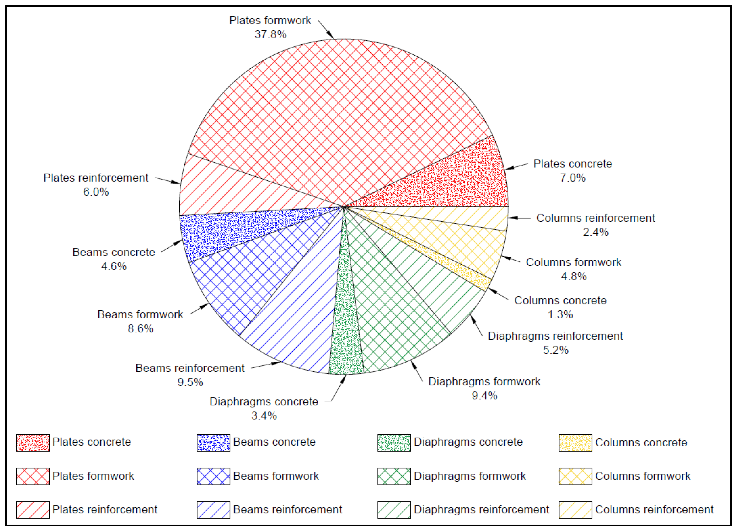
| Plates | 14,546.59 | 78,385.77 | 12,370.22 | 105,302.59 | 50.8% | |
| Beams | 9480.00 | 17,820.80 | 19,669.39 | 46,970.19 | 22.7% | |
| Diaphragms | 7116.14 | 19,376.32 | 10,770.65 | 37,263.12 | 18.0% | |
| Columns | 2780.00 | 9976.00 | 4928.10 | 17,684.10 | 8.5% | |
| Sum | Amount | 33,922.73 | 125,558.90 | 47,738.37 | 207,220.00 | 100.0% |
| Percentage | 16.4% | 60.6% | 23.0% | 100.0% | ||
Publisher’s Note: MDPI stays neutral with regard to jurisdictional claims in published maps and institutional affiliations. |
© 2022 by the authors. Licensee MDPI, Basel, Switzerland. This article is an open access article distributed under the terms and conditions of the Creative Commons Attribution (CC BY) license (https://creativecommons.org/licenses/by/4.0/).
Share and Cite
Yousif, S.; Saka, M.P.; Kim, S.; Geem, Z.W. Optimum Design of Reinforced Concrete Folded Plate Structures to ACI 318-11 Using Soft Computing Algorithm. Mathematics 2022, 10, 1668. https://doi.org/10.3390/math10101668
Yousif S, Saka MP, Kim S, Geem ZW. Optimum Design of Reinforced Concrete Folded Plate Structures to ACI 318-11 Using Soft Computing Algorithm. Mathematics. 2022; 10(10):1668. https://doi.org/10.3390/math10101668
Chicago/Turabian StyleYousif, Sayed, Mehmet Polat Saka, Sanghun Kim, and Zong Woo Geem. 2022. "Optimum Design of Reinforced Concrete Folded Plate Structures to ACI 318-11 Using Soft Computing Algorithm" Mathematics 10, no. 10: 1668. https://doi.org/10.3390/math10101668