1. Introduction
Manufacturing is a wealth-generating activity, and, thereby helps ensure the economic well-being of a country. Nowadays, computer-aided hardware devices (e.g., Computer Numerically Controlled (CNC) machine tools, three-dimensional (3D) printers, robots, programmable logic controller, 3D scanners, Coordinate Measuring Machines, computerized assembly lines, and alike) and software packages for solid modeling (e.g., 3D Computer-Aided Design (CAD) and Computer-Aided Manufacturing (CAM) packages) are extensively used to perform the activities related to product life cycle (conceptualize, design, manufacture, assemble, distribute, use, maintain, and recycle). Therefore, the individuals who can design, analyze, use, and maintain the hardware devices and software packages mentioned above are essential for the economic growth of a country (in this article, the above-mentioned devices and software packages are collectively referred to as CAD/CAM). As such, higher education institutes all over the world need to educate students with the knowledge and skills of CAD/CAM and other relevant issues for meeting industry needs [
1,
2,
3]. Thus, engineering degree programs all over the world offer courses related to CAD/CAM [
4]. Similar to the courses where the students learn engineering science (e.g., [
5]), a technology-oriented course also needs customized methods and tools for the educational effectiveness and outcomes assessment (e.g., see the tools developed for the courses related to CAD [
6] and courses related to the Internet of Things (IoT) [
7]). This is true for the education of CAD/CAM in the academia. Some of the selected articles that deal with the educational aspects of CAD/CAM in academia are described below. Araki [
8] and Zhao et al. [
9] described the contents to educate learners to use the CAD/CAM packages, which are made available through the multimedia network. deWeck et al. [
10] described the students’ activities and their performances while using commercially available CAD/CAM systems and other relevant software packages. The purpose is to provide students with the opportunity to materialize a conceptual design. Ishitsuka et al. [
11] described the methodology to teach CAD/CAM using an exercise for creating the CNC program from a given solid model prepared by using the CAD system. Lin et al. [
12] described the teaching methodology to integrate CAD with CAM for undergraduate students. Alemzadeh [
13] described how to introduce CAD/CAM from the perspective of concurrent design for senior-level engineering students. Kaneko and Kashimoto [
14] developed a customized computer-aided tool for educating students with the knowledge and skills of CAD/CAM. Abouelala et al. [
15] described a methodology for selecting a CAM package for educating students with the knowledge and skills of CAD/CAM, considering the opinions of the stakeholders. Moschonissiotis and Vosniakos [
16] developed a methodology to train individuals with the knowledge and skills of CAD/CAM where a set of structured rules and utilization of these rules in process planning are emphasized for achieving tangible results.
However, consider the issue of the assessment of students’ performance. In this regard, Main and Staines [
17] reported that the practical examinations are a more informative and efficacious method for assessing the students’ performance in CAD/CAM. Hamade et al. [
18] reported how to evaluate the skills of the senior-level students while building solid models using commercially available CAD packages. In both cases, the learners are the mere users of the available technology. Whether or not the students are aware of how the systems work and why the systems can produce the desired shape or product has not been the issue of the assessments mentioned above. This is perhaps not the goal of the outcomes-oriented education programs recommended by the accreditation bodies (e.g., ABET,
http://www.abet.org). The reason is that the educational activities underlie three aspects: namely, idealism, realism, and pragmatism. The idealism and realism prepare an individual to be a “knower”, whereas pragmatism prepares an individual to be “doer” only. Therefore, several outcomes are set so that the student becomes a “knower” and “doer” simultaneously. As far as the ABET-recommended outcomes are concerned, the content of a course (or a series of courses) regarding CAD/CAM should help students attain at least the following four outcomes: (1) an ability to apply the knowledge of mathematics, science, and engineering; (2) an ability to design a system, component, or process to meet the desired needs; (3) an ability to identify, formulate, and solve engineering problems; and (4) an ability to use the techniques, skills, and modern engineering tools necessary for engineering practice. At the same time, the contents must be derived from the fundamental aspects of CAD/CAM, as schematically illustrated in
Figure 1. In particular, the region defined by the dotted box in
Figure 1 illustrates the central issues underlying CAM. As shown in
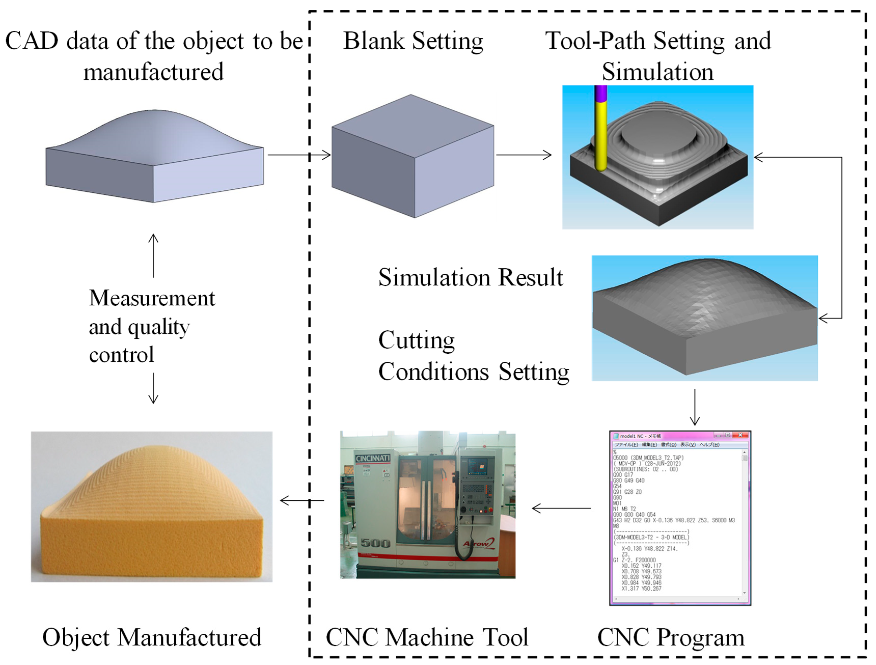
Figure 1, in CAD/CAM, the CAD data of the object to be manufactured becomes the main input. Based on this input, the user sets the blank and the cutting tool to be used. The user then selects the appropriate tool-paths (morphing, zigzag, and/or contour parallel), the cutting tool parameters (number of cutting edges, tool nose radius, tool length, and/or tool diameter), and cutting operation (rough-cut and or finish cut). Based on the selections that the user made, the CAD/CAM package simulates the tool-paths, showing their effects on the blank. When the simulation result satisfies the user (i.e., a simulation result produces the desired shape), the CAD/CAM package creates the CNC program, i.e., it formats (i.e., post-processes) the cutter locations given by the tool-paths and the cutting conditions (feed rate, cutting velocity, depth of cut, and alike) in a way so that the controller of the CNC machine tool can understand and execute the program. Once the user is satisfied with the program, it can be executed to produce the desired shape or product, as schematically illustrated in
Figure 1. The digital measurement technology can be used to report the dimensional and form accuracies, as well as the surface roughness for the sake of quality control.
Based on the above-mentioned description of the educational aspects of CAD/CAM, this article presents three tutorials. Thus, the remainder of this article is organized as follows:
Section 2 describes the first tutorial for calculating the tool-path for machining a 2D shape given by a parametric curve.
Section 3 describes the second tutorial for determining 3D tool-path for machining a freeform surface, which is given by a parametric surface.
Section 4 describes the last tutorial, where one integrates the advanced machine tools (e.g., hexapod-based machine tools) and geometric modeling of freeform surfaces.
Section 5 provides the concluding remarks of this study.
2. Tutorial for 2D Tool-Path Generation
As shown in
Figure 1, one of the major tasks of CAD/CAM is to create the tool-paths. How do the CAD/CAM packages generate the tool-paths? The tutorial that helps a student understand the process of creating the tool-paths can also help achieve the outcomes (1)–(4) as mentioned above. According, this section describes a tutorial for generating a two-dimensional (2D) tool-path. For the sake of better understanding, the parametric curve-based tool offsetting method is used in the tutorial. The description is as follows:
Parametric curves are extensively used to represent a large variety of engineering shapes and parts [
19,
20]. The following equation defines a parametric curve denoted as
C(
t).
In Equation (1), Pi is the i-th control point, Bi (t) is the blending function associated with Pi, and t is the parameter so that t ∈ [0,1]. As such, the matrix that is denoted as [t], which is a row matrix, is called the parameter matrix. The matrix that is denoted as [M], which is an n × n matrix, is called the shape matrix. The matrix that is denoted as [G], which is a column matrix, is called the control point, vertex, or geometric matrix.
When one models a shape using a parametric curve as defined in Equation (1), the user must decide the number of control points (
n), the set of control points {
Pi |
i = 1,...,
n}, and the blending functions {
Bi |
i = 1,...,
n}. The blending functions depend on both the number of control points and the type of parametric curve (e.g., Bezier curve, B-spline, and alike). The number of control points and the type of the parametric curve decide [
M] and [
t]. For example, consider the case of a parametric curve called the quadratic B-spline (
CQB(
t)). The coordinates of the three arbitrary control points (
Pp1,
Pp2, and
Pp3) are needed to construct the [
G] for
CQB(
t). Here, the subscript “
p” denotes one of the coordinates out of
x,
y, and
z, i.e.,
p ∈ {
x,
y,
z}. The equation of a coordinate of
CQBp(
t) is as follows:
As such, for a quadratic B-spline, [t] = [t2 t 1], [G] = [Pp1 Pp2 Pp3]T, and [M] is a 3 × 3 matrix, as shown in Equation (2) between [t] and [G].
If one needs to find out the tangent of
CQBp(
t), denoted as
C′QBp(
t), [
t] is replaced by a matrix denoted as [
t]′. The elements of [
t]′ are the first derivative of the elements of [
t]. Thus,
C′QBp(
t) is given as follows:
An instructor can assign students to construct the equations of other B-spline curves using the concept of shape matrices as well as the tangent vectors. This way, the students learn more intensely how to apply the knowledge of mathematics and science to an engineering problem.
Sometimes, a single quadratic B-spline curve is not good enough to model the entire object (or any other parametric curves in this matter). In this case, the modeling is carried out by using several curves. Suppose that one models a shape using a finite set of B-spline curves that are denoted as
,
j = 1, 2, .... As such, all of the possible pairs of two consecutive curves denoted as
and
are connected in a piecewise manner, fulfilling the
C0 and
C1 continuity [
19,
20]. This means that the last point of a curve is equal to the first point of the next curve (
C0 continuity), and the slope at the last point of a curve equal to the slope at the last point of the next curve (
C1 continuity). Thus, the following proposition must be true in the modeling process:
The assignments based on the formulation defined in Equation (4) help students achieve the outcomes (2) and (3), i.e., an ability to design a system, component, or process to meet the desired need, and an ability to identify, formulate, and solve engineering problems. It is worth mentioning that the students have the choices of using other parametric curves (e.g., Bezier curves) to model the given object or shape. However, basic concept remains the same, as described above.
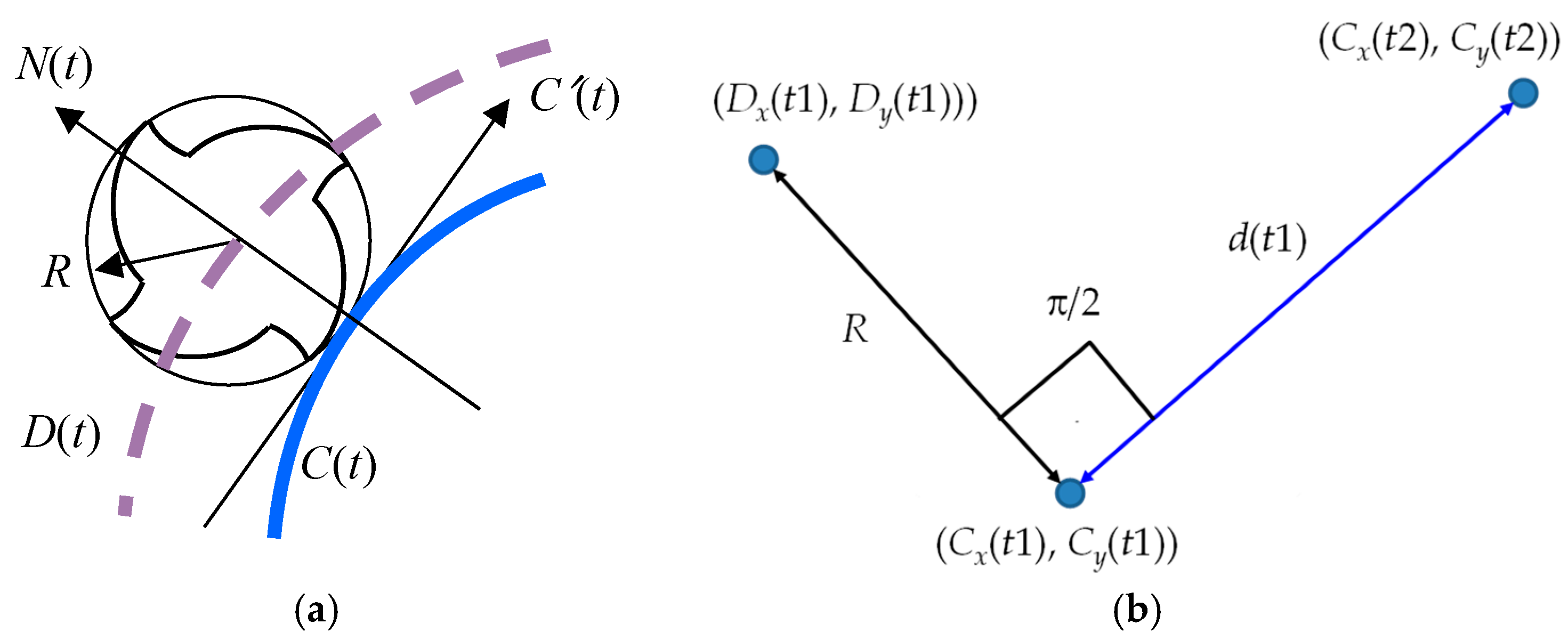
In addition, given a 2D parametric curve, as defined by Equation (1), the students can be assigned to derive an offset curve denoted as
D(
t), as schematically illustrated in
Figure 2a. The offset curve becomes the tool-path for machining the shape (i.e.,
C(
t)). The CNC program ensures that the center of the cutting tool follows
D(
t). Thus, this information is taken as the cutter locations for constructing a CNC program (
Figure 1).
Now, for determining
D(
t), one first needs to determine the normal vector
N(
t) for each set of two consecutive points on
C(
t). The distance between
C(
t) and
D(
t) is equal to the radius of the cutting tool that is denoted as
R. Thus, the expression of the offset curve
D(
t) is as follows:
Figure 2b schematically illustrates how one can calculate a point denoted as
D(
t1) = (
Dx(
t1),
Dy(
t1))) on the offset curve
D(
t) using two points denoted as
C(
t1) = (
Cx(
t1),
Cy(
t1)) and
C(
t2) = (
Cx(
t2),
Cy(
t2)) so that
t1,
t2 ∈ [0,1] and
t2 =
t1 +Δ
t, where Δ
t is a very small positive number (e.g., 0.01). Since the line passing through the points
D(
t1) and
C(
t1) and the line passing through the points
C(
t1) and
C(
t2) are orthogonal to each other, the coordinates of
D(
t1) can be calculated as follows:
In Equation (6),
d(
t1) denotes the distance between the points
C(
t1) and
C(
t2), which is calculated as follows:
It is worth mentioning that the students need to decide the combinations of the signs (plus–minus or minus–plus) to use the Equation (6). The combination depends on the orientations of the points denoted as
C(
t1) and
C(
t2) (i.e., clockwise or anticlockwise direction). The case shown in
Figure 2b results in a clockwise direction. For this case, the combination of signs is minus and plus for calculating
Dx(
t1) and
Dy(
t1), respectively. At the same time, the student may recall the vector algebra while validating Equation (6), particularly the concepts of unit vector, vector dot product, direction cosine, and alike.
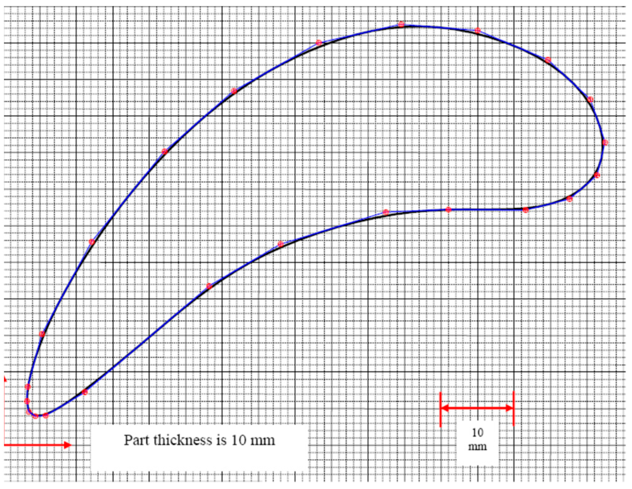
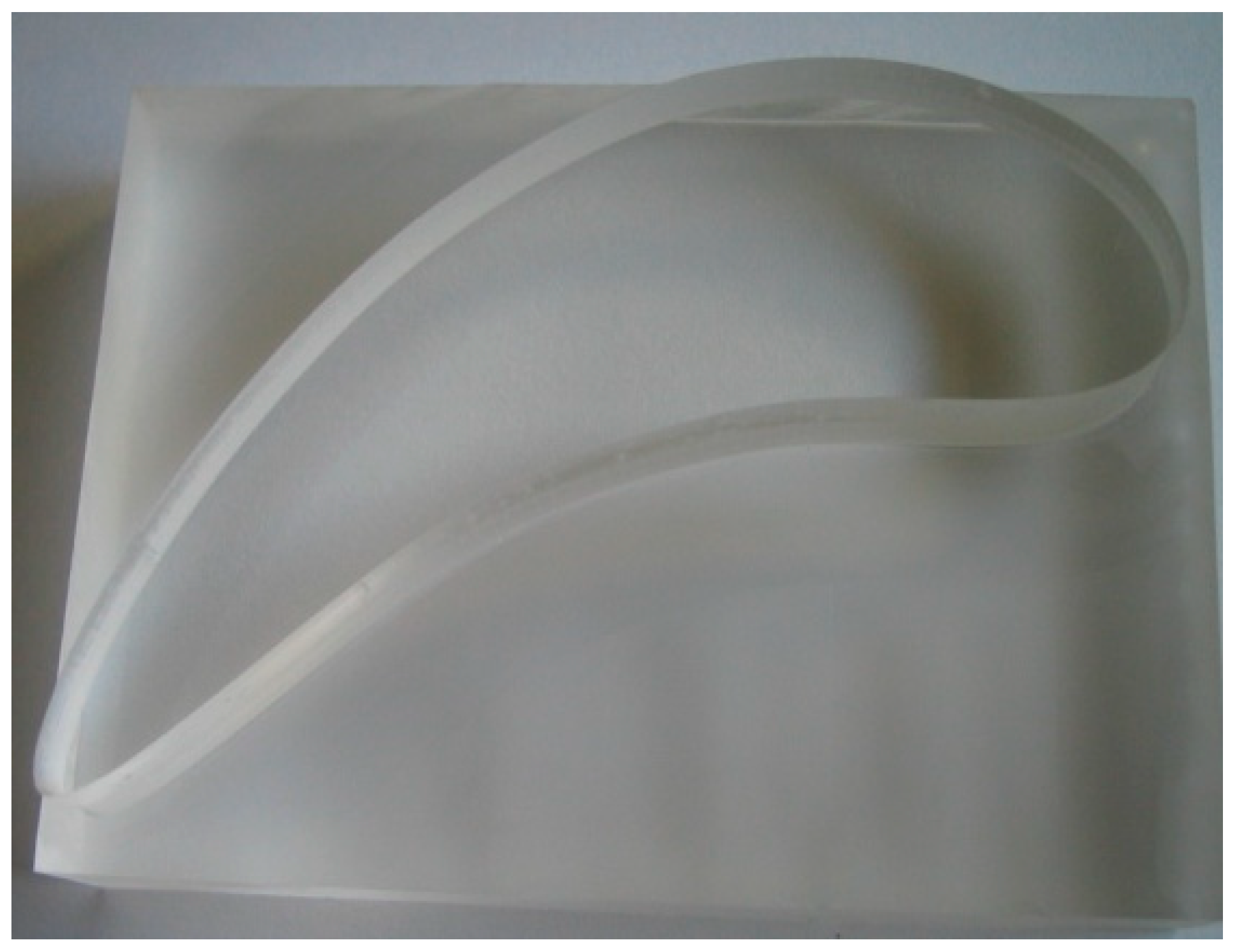
As an exercise, the students can consider the airfoil shape shown in
Figure 3. The instructor can introduce the shape to the students by plotting it on a graph paper, as shown in
Figure 3. Later, the students can manufacture the part, as shown in
Figure 4. In this case, the students first create the CNC program and use it for machining the part using a CNC machine tool (
Figure 1). The students can be given two options to do this, as described below.
In the first option, the students reconstruct the shape shown in
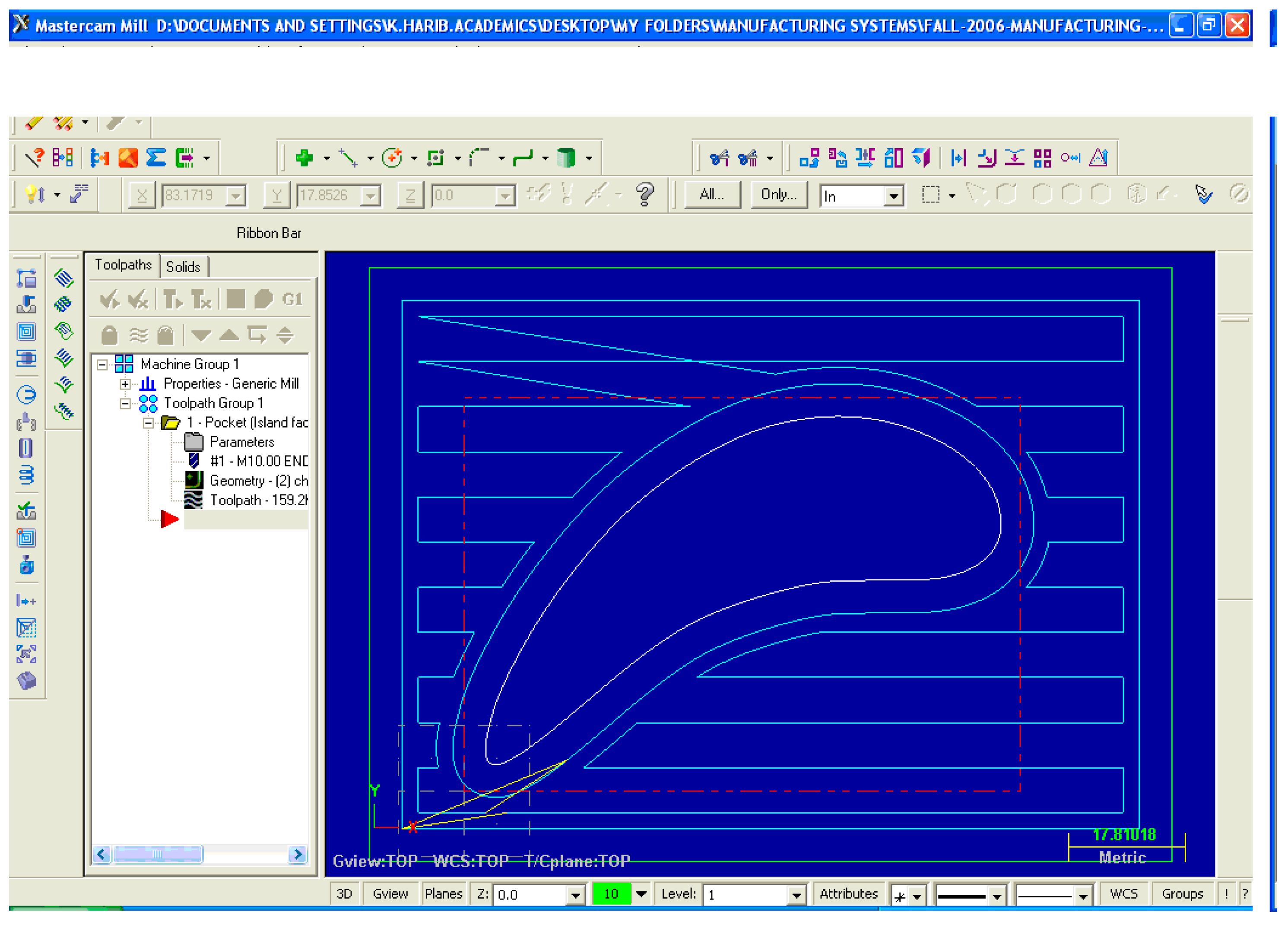
Figure 3 using a CAD software and input the CAD data to a CAD/CAM software for generating the CNC program. In this case, the performance of the students can be determined by an output, as shown in
Figure 5. This is the screenprint of the tool-path generated by commercially available software (MasterCAM
TM) from the CAD data of the shape that is shown in
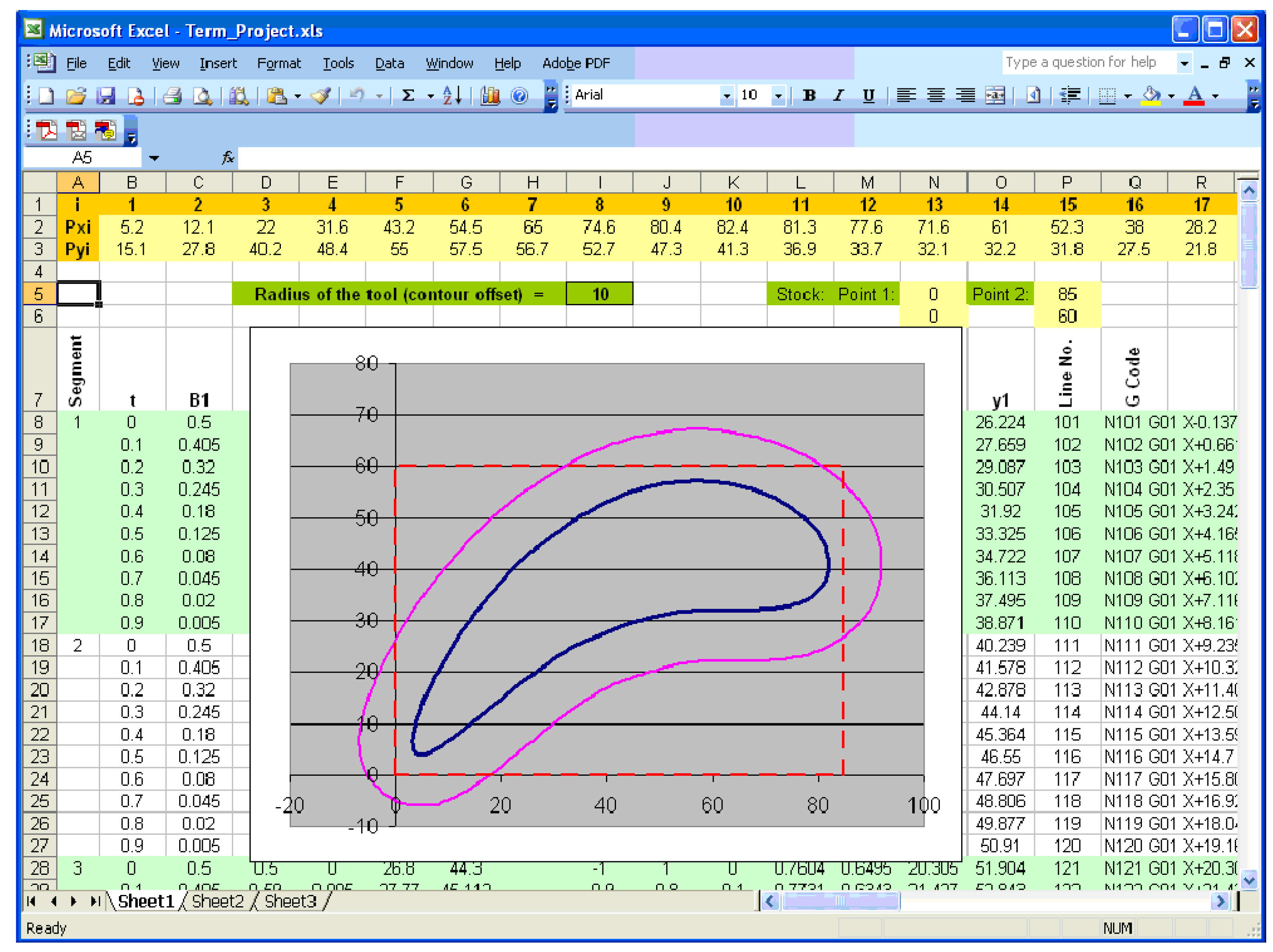
Figure 3. This type of learning ensures that the students can use the techniques, skills, and modern engineering tools that are necessary for engineering practice. However, the students’ ability to apply the mathematical and engineering science knowledge gained in other courses cannot be tested or enhanced by using such an exercise. Thus, the students should be given the other option to create the tool-path by applying Equations (1)–(7). The emphasis should be given to both how to model the shapes using some piecewise B-spline curves, and then to create the offset curve
D(
t). The students should create the CNC program, too, using the information of offset curve
D(
t). The screenprint shown in
Figure 6 shows one of the expected achievements of the students. The CNC program can be observed in
Figure 6. Comparing the results obtained from the commercial CAD/CAM package (
Figure 5) and the spreadsheet-based analytical approach (
Figure 6), the instructor can evaluate the performance of the students and explain other issues (e.g., how the tool should approach the blank for the first time, how the tool should exit once the countering is done, how to optimize the cutting conditions, how to select the optimal cutting tool, and alike).
3. Tutorial for 3D Tool-Path Generation
This section describes a tutorial for 3D tool-path generation. This is an advanced topic compared to the previous one. The 3D tool-paths are an integral part of modern manufacturing, because freeform parametric surfaces are extensively used to model a large variety of shapes [
19,
20]. For constructing a freeform surface, a surface patch is generated from the product of two sets of parametric curves for two parameters,
u and
v. Therefore, the equation of a freeform parametric surface denoted as
C(
u,
v) is as follows:
In Equation (8),
Pik are the control points or vertices, and
Bik(
u) and
Bik(
v) are the blending functions. The expression of
C(
u,
v) in matrix form is as follows:
In Equation (9), [u] is a row vector having n elements, [M] is an n × m shape vector, [P] is an n × m vector of one of the coordinates of the control points, and [v] is a column vector having m elements.
For a cubic Bezier surface [
19,
20], the freeform surface denoted as
is given by the following equation:
In Equation (10), the shape matrix
is given as follows:
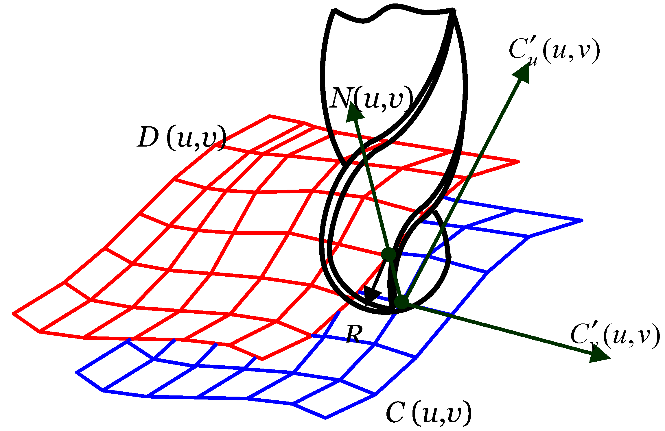
Now, the question is: how to create the tool-path to machine a surface similar to the one defined in Equation (10)? The machining of the surfaces similar to the one defined in Equation (10) is often done by using a ball-nose end-mill cutter, as schematically illustrated in
Figure 7. The center of the ball-nose moves along an offset surface denoted as
D(
u,
v) (
Figure 7). As shown in
Figure 7, generating the offset surface
D(
u,
v) means that each point on
C(
u,
v) is mapped into its corresponding point on
D(
u,
v) by shifting it along the normal direction of
N(
u,
v). This requires two tangential vectors that intersect at the point, as shown in
Figure 7. Thus, the expressions of the tangent vectors in the
u and
v directions, respectively, are as follows:
The normal vector
N(
u,
v) is thus obtained from the cross-product of the two tangential vectors resulting in the following expression:
Once the normal direction is determined, the offset surface is determined similarly to the previous case, which is as follows:
In Equation (15), R is the radius of the ball-nose of the end-mill cutter.
To exercise the above-mentioned offsetting technique for freeform surfaces, the students can use a programming tool to generate the codes required for the CNC program.
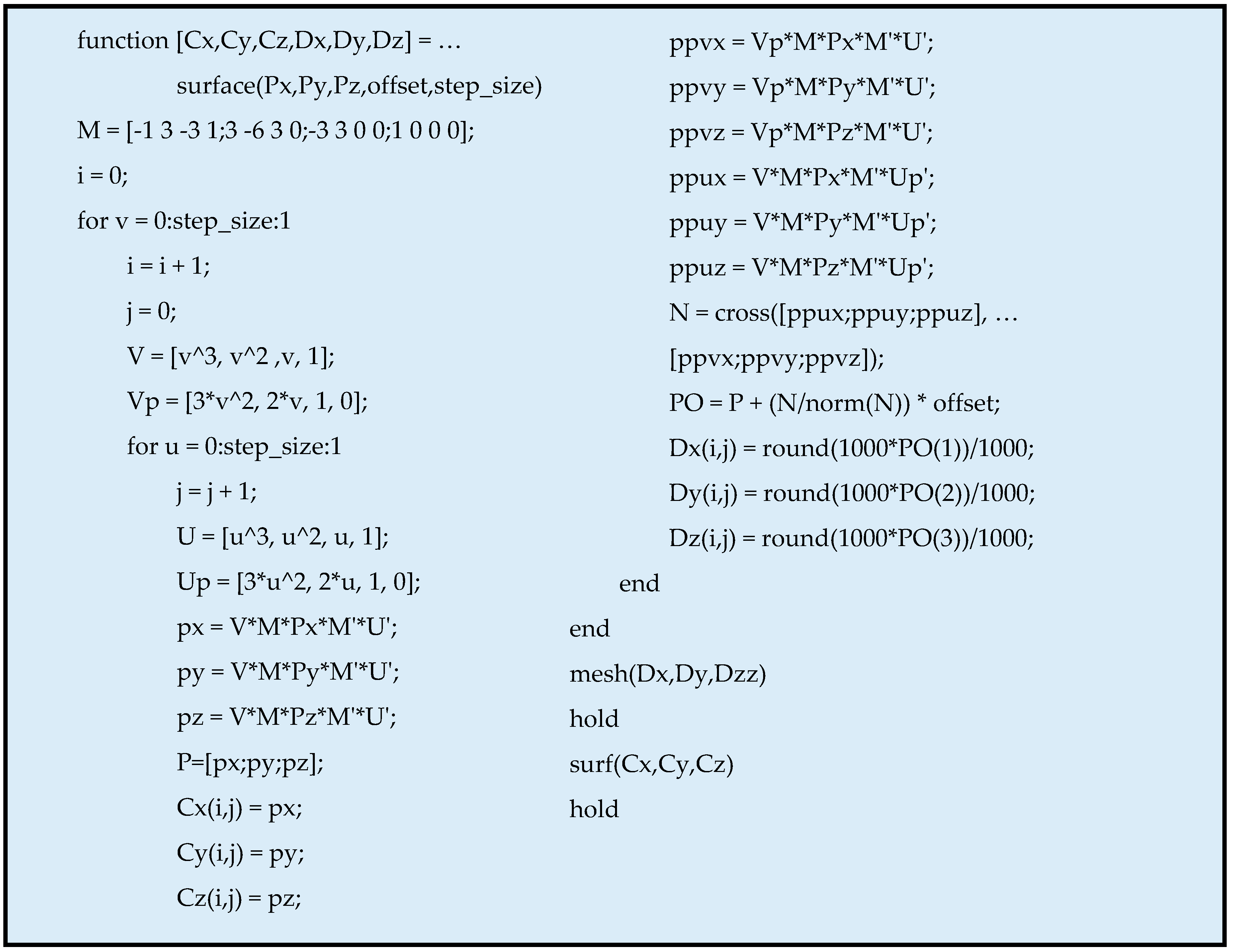
Appendix A shows the required program written in MATLAB
TM in terms of two functions. The function shown in
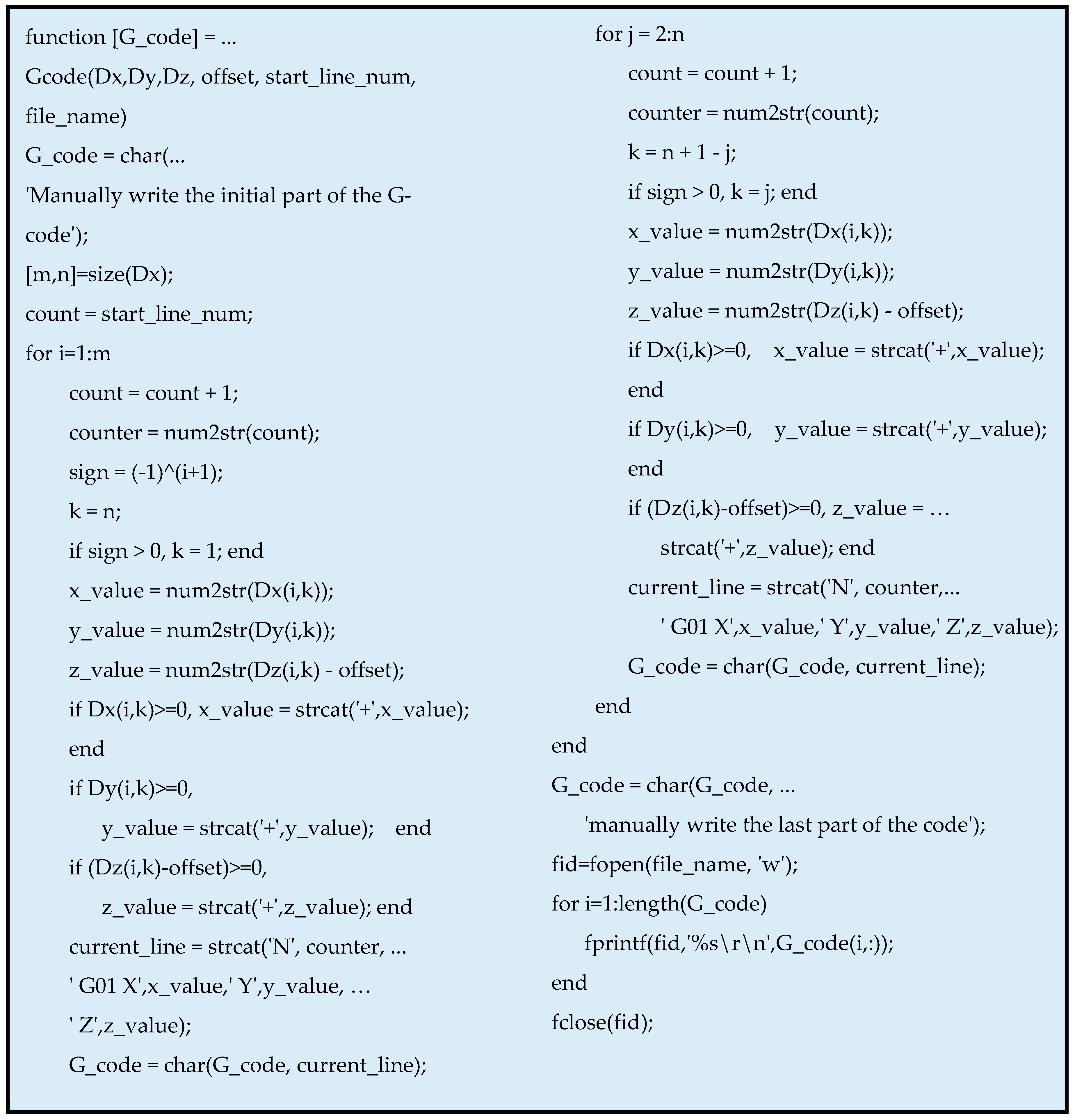
Figure A1 creates the offset surface from the given Bezier surface in accordance with Equations (10)–(15). It also plots the Bezier and offset surfaces. On the other hand, the function shown in
Figure A2 is used for generating the codes (G-codes) for the CNC programming. It writes the code to a text file, which can be edited based on the requirement of the given CNC controller. Needless to say, the function shown in
Figure A2 takes the necessary outputs from the function shown in
Figure A1.
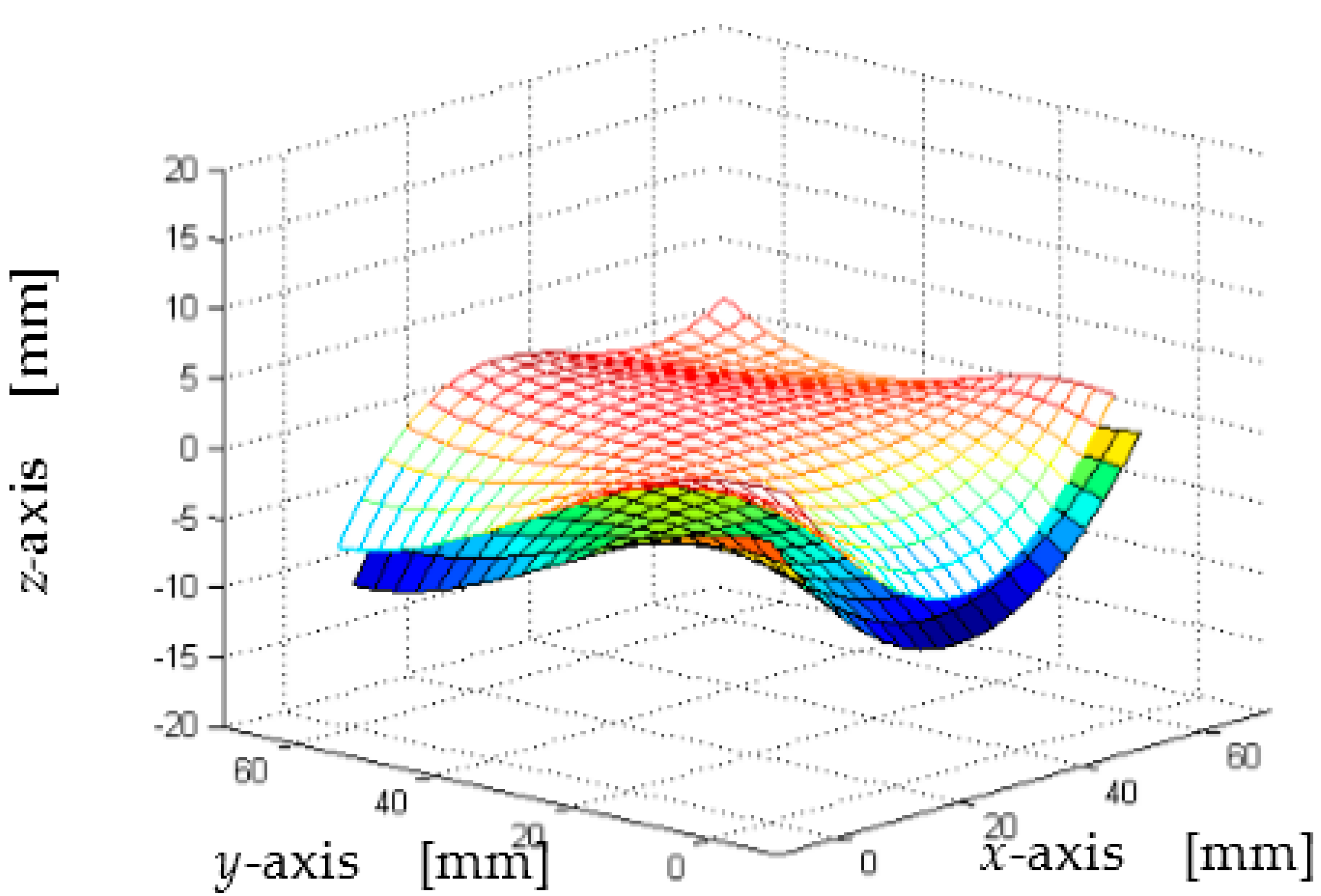
Figure 8 and
Figure 9 show the expected outcomes of the tutorial. In particular,
Figure 8 shows the given and offset surfaces, which is the output of the function shown in
Figure A1. For this case, the coordinates of the control points are shown below in the form of matrices.
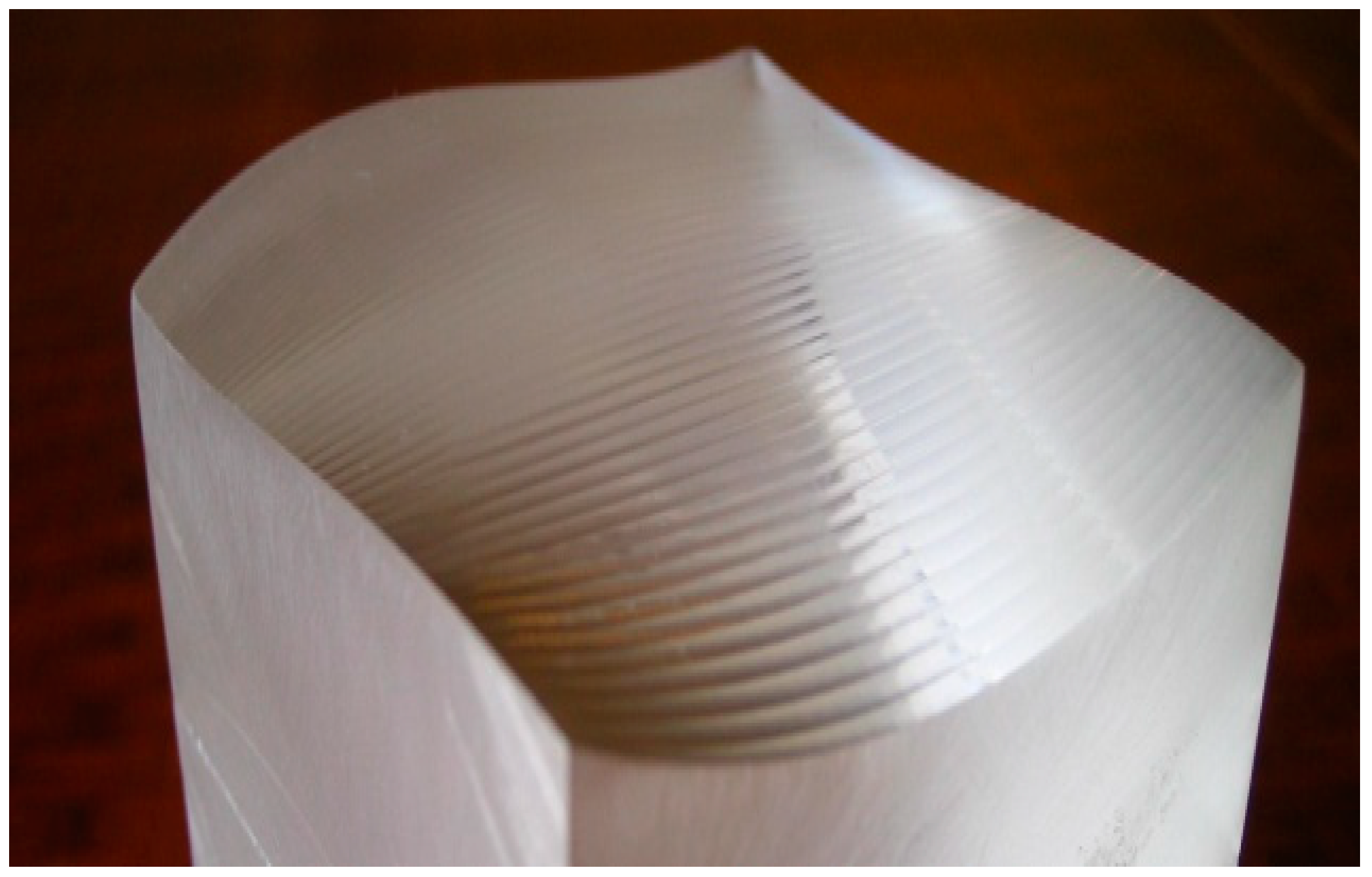
Figure 9 shows the freeform surface manufactured by using a three-axis CNC machine tool (
Figure 1). The sharp marks seen on the manufactured freeform surface are the tool-path marks. This is due to the coarseness of the increment of
u and
v (the increment was 0.05) and tool diameter (offsetting for a 4-mm radius of the ball-nose end-mill cutter). The students can be assigned to make necessary changes in the formulation to reduce the sharpness of the marks. Similar to the previous tutorial, the students can achieve all of the outcomes (the outcomes denoted as (1)–(4)) mentioned above by solving the problems underlying this assignment.
4. Programming Advanced Machine Tools
The previous two tutorials are meant for educating students with the knowledge and skills of CAD/CAM technology using conventional machine tools with a serial kinematics structure. This is not the end. The field is evolving very fast. From this perspective, the advances in the CNC machine tools can be considered. In particular, as a replacement of the conventional CNC machine tools (having a serial kinematics structure), researchers have been studying the CNC machine tools that have parallel and hybrid kinematics structures [
21,
22]. These machine tools are more economical, light, and functional compared to the conventional ones. Moreover, in the near future, these machine tools are expected to play their role in manufacturing.
The previous two tutorials are meant for educating students with the knowledge and skills of CAD/CAM technology that can be implemented using the conventional machine tools. Note that the conventional machine tools have a serial kinematics structure. These machine tools are by nature heavy and less economical. However, researchers have been studying a new type of CNC machine tools that have parallel or hybrid kinematics structures [
21,
22]. These machine tools are more economical, light (portable), and functional compared to the conventional ones, and thereby are expected to play their roles in the near future. Therefore, the students majoring in manufacturing, mechatronics, and robotics are likely to engage in scholarly activities where the parallel and hybrid kinematics’ structure-driven machine tools are conceptualized, analyzed, designed, and implemented. As a result, the relevant senior-level undergraduate and graduate-level courses must prepare the students with the knowledge and skills of parallel and hybrid kinematics structures. Based on this contemplation, this section presents a tutorial that is meant for educating interested students with the knowledge of how to program a parallel kinematics machine tools for machining a 3D shape. The description of the tutorial is as follows:
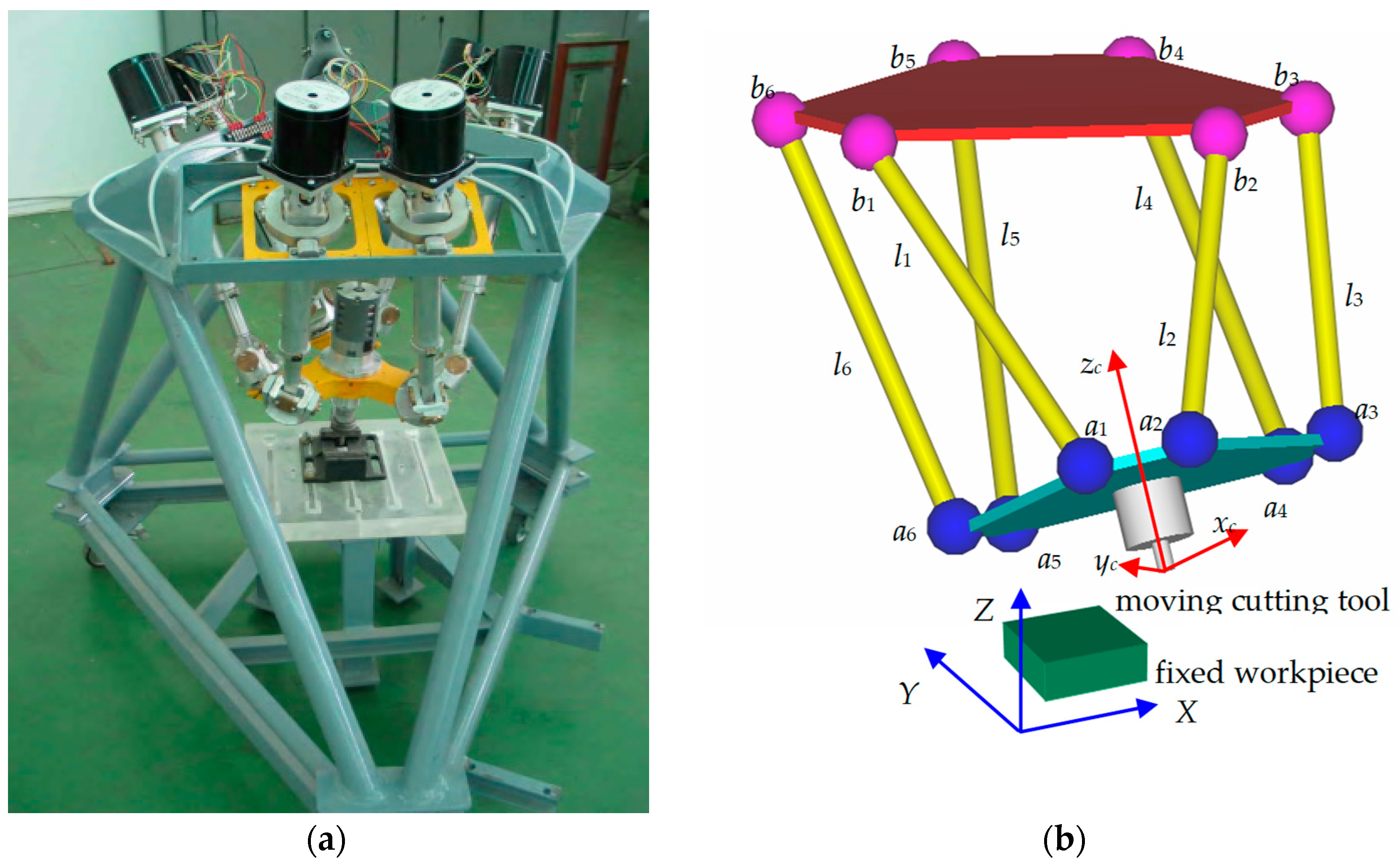
Consider CNC machine tools [
21] that have parallel kinematics structures, as shown in
Figure 10. As seen in
Figure 10, the cutting motion is controlled by six extendable linear actuators that carry the cutting tool platform. See Harib et al. [
21] for more detail on the kinematics analysis and the trajectory planning. However, for the
i-th actuator, the extension
li is computed as follows:
In Equation (16), s and c denote the sine and cosine functions, respectively; (Xbi, Ybi, Zbi)T is the constant position vector of the i-th attachment point bi with respect to the world coordinate frame W; (xai, yai, zai)T is the constant position vector of the i-th attachment point ai with respect to the cutting tool coordinate frame C; (X, Y, Z)T is the position vector of the tip of the cutting tool with respect to W; and A and B are the angles that define the orientation of the cutting tool with respect to W; A is the horizontal rotation of the vertical plane that contains the cutting tool axis, and B is the tilting angle of the cutting tool inside that plane.
To machine a freeform surface similar to the one described in the previous section, the following procedure can be used.
Step 1: Calculate X, Y, and Z from the three coordinates of the parametric surface C(u,v).
Step 2: Calculate the normal vector N(u,v) according to Equation (14).
Step 3: Calculate the unit vector along the cutting tool
n(
u,
v) as follows:
The third column of the rotation matrix in Equation (16) is the unit vector along the axis of the cutting tool. This means that:
Step 4: Determine
A and
B, as follows:
It is worth mentioning that if the students use a package of five-axis milling, they will be able to determine (X,Y,Z,A,B) without any effort provided that a flat-end mill is used in the programming. However, if the students follow the above steps, they realize the whole process without any support of a commercial package. This way, the students having more advanced analytical abilities in CAD/CAM can be nurtured.
5. Concluding Remarks
The authors have been offering CAD/CAM and related courses for a long time for both undergraduate and graduate students of engineering degree programs. The authors have been observing that if the commercial packages are used for creating the tool-paths automatically, the students can gain the application ability, but they fail to gain the analytical ability, i.e., they become doers, but not knowers. On the contrary, the students can achieve the same using the presented tutorials where they do not need to use any dedicated CAD/CAM packages. This means that the presented tutorials contribute positively to the objective of strengthening students’ ability to apply the knowledge of mathematics and engineering science, making students both doers and knowers together. Students also learn that designing a shape using CAD software is not everything. If the design is not converged to a CNC program, the materialization of the shape does not occur. This way, the students become aware of the activities of a product life cycle more intensely, which should be the case from the perspective of their future employers. In the presented tutorials, the students are introduced to the concept of parametric curves and surfaces. This improves their knowledge of dealing with the shapes having complex geometry. In addition, the students are exposed to hexapod-based machine tools. This makes the students aware of the CNC technology advancing rapidly. Therefore, it is essential for the students to understand which module of a system of CAM (or CAD) affects the operations of such machine tools from the perspective of the structure of a machine tool, as well as from the perspective of the shapes of the parts to be manufactured. Moreover, in the presented tutorials, the students get the opportunity to use standard computing and visualizing tools (e.g., ExcelTM and MATLABTM). This makes them competent enough while using these tools in other courses, too. However, the instructors or the students have the freedom to use any computing platform and programming languages they prefer, although the descriptions here show the usages of spreadsheet and MATLABTM coding. Having said that, it is not meant that the mathematical formulations presented in this article should not be obeyed. The first two tutorials can be offered to the senior-level undergraduate students enrolled in mechanical, manufacturing, and industrial engineering degree programs, whereas the other tutorial is recommended for the students who want to design mechatronics devices. While offering the tutorials, the authors recommend the approach called thematic integration or problem-based learning (PBL). In the case of thematic integration, the instructor may offer the tutorial in line with the contents of other courses (e.g., engineering design or mechanics course), so that the geometric shapes used in the other relevant course can be used in the proposed tutorials. While offering the tutorials as PBL, the students should be given a chance to form a team. The team then sets the objectives and outcomes based on the contents of the tutorials. Finally, the students present their teamwork for the evaluation.
Nevertheless, the presented tutorials can be modified by incorporating more outcomes (e.g., contemporary issues, teamwork, ethics, and alike) and the contents that are needed for mastering the digital manufacturing technology. Particularly, the issue of functioning effectively in a multidisciplinary team, and being aware of the professional and ethical responsibility, can also easily be accommodated more explicitly with the presented tutorials if the relevant degree program needs it. Similarly, the tutorials can easily be modified to accommodate the issues of sustainability and sustainable manufacturing [
23], reverse engineering [
24], design for additive manufacturing of complex shapes [
25], and e-making [
26]. At the same time, the issues of meaningful learning using a set of concept maps [
27] can be considered. It is worth mentioning that concept maps [
27] can represent the contents of the tutorials described in the article, and the students can even access them using their cell phones [
4]. Since the concepts underlying any topic of manufacturing are ultimately linked to the universal concept maps, namely, the sustainability universe, the control universe, the material universe, the precision universe, and the process universe [
4], one must be careful about this linkage while representing the tutorials using a set of concept maps. Otherwise, the desired learning objectives may not be materialized.


