1. Introduction
Advances in quantum technology have led educators to introduce students to quantum principles and phenomena at the earliest levels of education (
Ghimire et al., 2025;
Holincheck et al., 2024). The basic principles of quantization, indeterminism, and measurement can easily be introduced without much mathematical context. The technique of quantum key distribution (QKD) represents a situation that provides a tangible application of quantum principles. It is useful to introduce it as a way of giving a sense of purpose to the intriguing theory and to make quantum physics more relevant to our daily life.
QKD involves the use of quantum physics to generate a secure encryption key and ensure its secrecy (see
Raymer (
2017) for a general introduction). The technique is used to generate a one-time encryption key of binary numbers for use in secure communications. Setting the key involves sending single photons prepared in suitable quantum states between a sender (Alice) and a receiver (Bob). Because photons cannot be cloned, an eavesdropper (Eve) must destroy the photon in order to measure its state, and must subsequently resend it to avoid being discovered. The act of measurement by Eve will, depending on the circumstance, change the state of the light, and therefore introduce errors in the key-determining communication. These errors can be detected by the sender and receiver, who do checks as part of the communication.
QKD is governed by the indeterminism of quantum physics. It is easily implemented with photons. The binary choices for encoding data, 0 and 1, are conveyed by the polarization state of the light. The sending and detecting apparatuses have two (or more) possible bases in which the photon state is encoded. Bases are reference frames from which the state of the photon can be defined. In the context of polarization of light, one basis can be horizontal–vertical (HV). A polarization splitter channels photons based on their polarization and is used to detect the state of the light. If the photon is in a state that is one of the basis states of the measuring device, such as a horizontal or vertical state of polarization, then at the detection end, if the splitter is in the HV basis, the photon will
always exit the correct (H or V) splitter output. That is, the state will be measured with unit probability. Another basis is diagonal–antidiagonal (DA) (
with respect to horizontal). A polarization splitter rotated
would split photons that are diagonally or antidiagonally polarized with unit efficiency. In the Bennett–Brassard protocol (BB84)
Bennett and Brassard (
2014), the sender may send the photon in either the HV basis, or the DA basis. If the photon prepared in one basis (e.g., horizontal–vertical) is measured (split at the detection end) in the diagonal–antidiagonal basis (with a rotated splitter), then the photon will exit either output of the splitter with a 0.5 probability. That is, there will be full uncertainty on the outcome of the measurement (which port of the splitter the photon will exit). Moreover, an aspect of quantum physics is that the individual measurement outcome is inherently unpredictable. In this situation, Bob will not always measure Alice’s photon correctly. Therefore, the sender and receiver can exchange data with full certainty as long as they use the same basis (HV or DA) to encode and decode the state of the photon. To avoid eavesdropping, Alice can send photons randomly encoded in either the HV or DA bases. Bob would then also randomly use HV and DA detection (splitter) bases. After the communication, Alice and Bob would share their bases and discard the cases where they used different bases. They can do this without revealing the exchanged data.
If Eve intercepts and measures the state of the photon, she must also pick a basis, HV or DA, and resend the photon in the state in which it was measured. If Eve uses a basis that is not the same as Alice and Bob, then she will send the photon in a state that is not in the same basis as Alice. As a consequence, there will be a probability of 0.5 that Bob will not detect the state that Alice sent. This will introduce errors in the communication. To check for these errors, Alice and Bob can share a subset of their data and discard the communications if sufficient errors are found. The strength of the method is that eavesdropping can be detected via the communication errors. Thus, quantum physics can provide a mechanism for secure communications.
Hands-on experiences are vital for engaging students and challenging them to grapple with physical phenomena. Several QKD tutorials have been proposed (
Akdemir et al., 2021;
Bloom et al., 2022;
DeVore & Singh, 2020;
Kohnle & Rizzoli, 2017;
Utama et al., 2020). They focus on teaching the encryption technique using the Bennett–Brassard protocol (
Bennett & Brassard, 2014). QKD relies on the quantum properties of single photons. In an ideal real scenario, a single photon is sent from Alice to Bob. The use of single photons for demonstrating QKD requires sophisticated technology and equipment (
Bista et al., 2021). Simpler and lower-cost possibilities involve using lasers or LEDs that mimic the role of single photons (
Neto Mendes et al., 2025;
Thorlabs, n.d.). These still contain expensive materials that are hard to scale up. The University of Waterloo lists a 3D printing kit that has the elements of a scalable demo (
IQC, 2024). Such a demo aligns with the intent of this contribution. However, the outcomes are not optimal due to a mismatch between the light source wavelength and the inexpensive commercial waveplates used. In this contribution, I present an alternative set of components and methods.
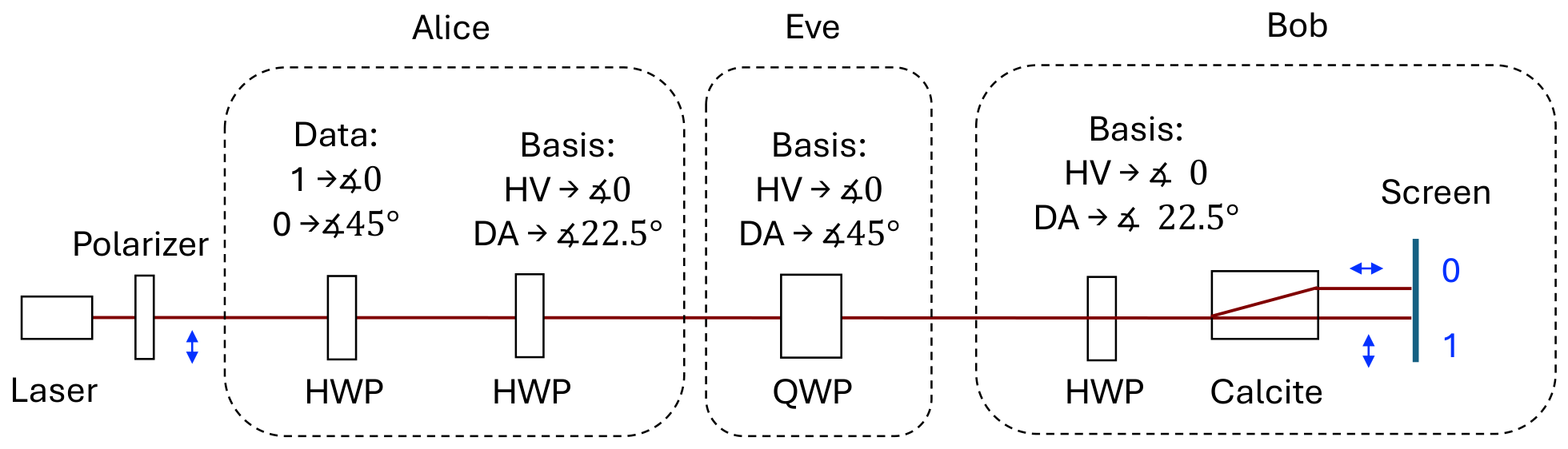
The demo presented here involves a diode laser for Alice, inexpensive polarization optics (polarizers and waveplates), including one to mimic Eve, and a polarization splitter and screen for Bob. The demo consists of a low-cost apparatus shown schematically in
Figure 1. It includes a laser, a fixed polarizer, four cellophane waveplates on swivel mounts, a calcite crystal, and a screen. In
Appendix A we list the components and their cost.
The laser just needs to be mounted so it sends the light in a particular direction at about 4 inches (∼10 cm) above the table plane. The laser is polarized, with its polarization oriented vertically. Laser power should be less than 5 mW (laser should be class 2 or 3R). The optics’ mounts are standard but adapted to this low-cost arrangement. The calcite crystal needs to be mounted in a specific orientation, which can be achieved using hardware at hand in the lab or by 3D printing.
2. Materials and Methods
2.1. Cellophane Waveplates
The demo uses three half-wave plates (HWPs). They are birefringent optical elements that impart a phase of between the polarization components along the fast and slow axes of the waveplate. As a consequence, they “flip” the polarization by twice the angle that the waveplate axis forms with the input polarization.
Because our laser source is an inexpensive diode laser lasing at 670 nm (nominally), we seek waveplates at that wavelength. Unfortunately, there are no inexpensive commercial waveplates that work well at this wavelength. Instead, we decided to investigate cellophane film, since previous studies report using it as a half-wave plate (
Beléndez et al., 2010;
Iizuka, 2003;
Kinyua et al., 2013;
Ortiz-Gutiérrez et al., 2001). Cellophane can be acquired commercially in rolls. Alternatively, inexpensive commercial items are usually packaged in cellophane. Cellophane wrappers make a practical enclosure for inexpensive articles and as a result are widely available at stores selling items such as novelties, office supplies, or food. We tested a number of USD 1 items from the “dollar store” (store in the U.S. selling only USD 1 items) and found wrappers with thickness ranging from 32
m (1.25 mil) to 41
m (1.6 mil). We found the best results with two sheets of cellophane stacked together. Cellophane sheets are birefringent due to the way they are manufactured. The optic axis is in the plane of the sheet and normally parallel to the edge. Conveniently, wrapped items already come in a cellophane pouch folded along an optical axis.
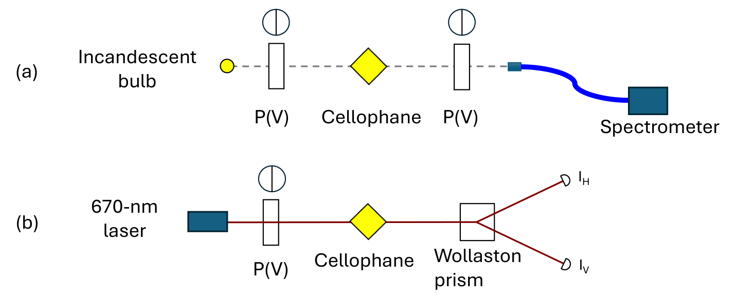
We tested the degree to which cellophane double-sheets behaved as HWPs at specific wavelengths. An HWP with its axis at 45 degrees to the input polarization (vertical or horizontal) changes the polarization to the orthogonal orientation. Our approach to test the cellophane sheets is shown schematically in
Figure 2a. We used an incandescent broad-spectrum light bulb as a source of light (LEDs do not work well because of their narrow spectrum). The cellophane sheet(s) were placed between two polarizers with the transmission axis vertical. We then measured the spectrum of the output light when the cellophane axis was oriented at
to the polarizers’ axes. We tested cellophane double sheets of different thicknesses (from different products).
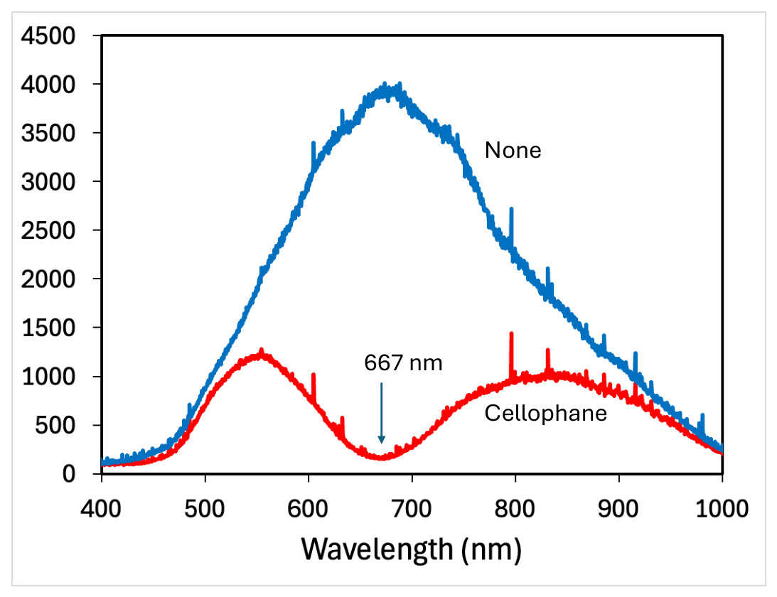
Figure 3 shows the result for a double-layer thickness of 64
m. Two products had wrappings with this thickness (plastic silverware and mini posterboard).
Other wrappers had other thicknesses. They produced a spectrum similar to the one in
Figure 3 but with other minima at other wavelengths: plastic cups (76
m, 690 nm), plastic cutlery (72
m, 726 nm), and paper cutouts (78
m, 815 nm).
It was straightforward to measure the retardance with the apparatus of
Figure 2b. We sent the laser through a vertical polarizer, keeping the cellophane double-sheet at 45 degrees. Then, with a good-quality polarization splitter (we used a Wollaston prism), we measured the intensity at the two outputs. The retardance angle is given by the following equation
Iizuka (
2003):
The retardance for the sample (double-ply) was measured to be
, which is close enough to
for our purpose. The uncertainty is the standard deviation of the measurements. Because Eve needs a quarter-wave plate, a single sheet suffices. We measured its retardance to be
, which is also good enough for our purposes. Uncertainties are based on propagated fluctuations in the power readings.
2.2. Swivel Mounts
2.2.1. Setting the Input State: 1 or 0
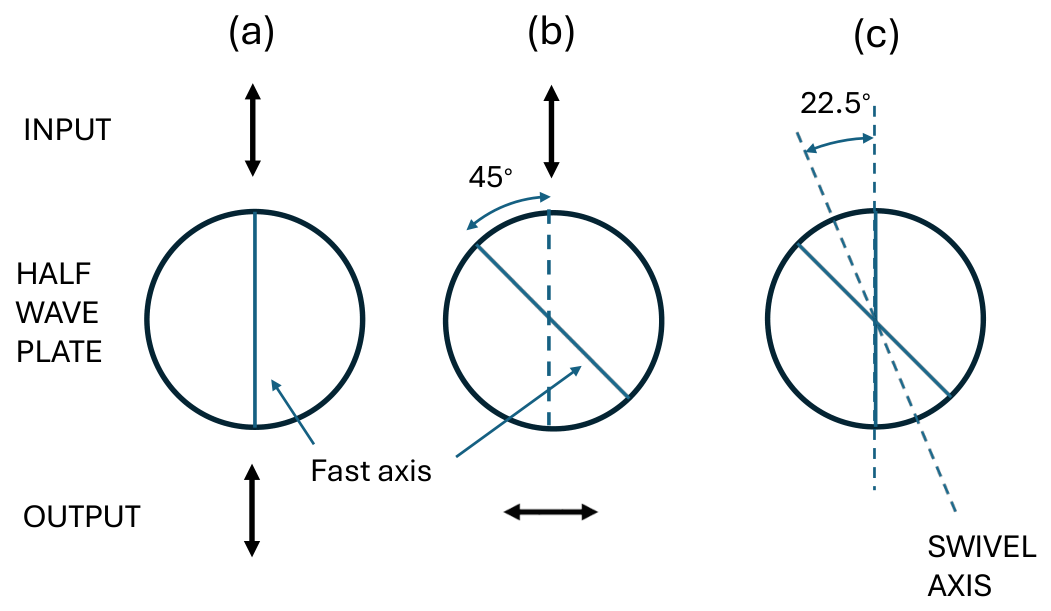
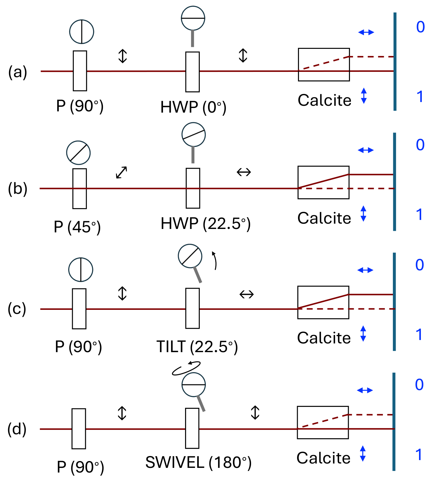
In implementing the BB84 protocol, Alice needs to provide a photon in state 0 and 1 in two different bases: horizontal–vertical (HV) and diagonal–antidiagonal (DA). We first encode the polarization state in the HV basis. Consider starting with a linearly polarized photon in the vertical orientation, which corresponds to state 1. We then pass it through an HWP. The HWP has fast and slow axes that are orthogonal to each other. For our application, it does not matter which axis we use. The results are the same with either one. If the angle of the HWP “axis” is 0 or
, the transmitted photon remains vertically polarized, as shown in
Figure 4a. If the HWP axis is set to
from vertical, the transmitted polarization is horizontal, and the photon is in state 0, as shown in
Figure 4b.
To flip from 0 to 1, we need to rotate the waveplate by
from the horizontal or vertical position. An HWP flips the polarization by twice the angle that its axis forms with the input polarization. A simple way to make this change is to swivel the mount about an axis forming
with the vertical, flipping the axis between two positions: 0 and
, as shown in
Figure 4c. Using the swivel mount is easy and avoids the need to set waveplates to the proper angle using (not inexpensive) rotational mounts, which could distract students from understanding the situation, because of the half-angles involved.
There are a couple of details in this implementation. The 3D-print files for the mount were available online (
PrintedLabs, n.d.), but the mount had a 1/2–13 tapped hole for attaching a post. Ideally, we want a 1/4–20 hole for attaching a 1/2-inch diameter post. We solved this by obtaining an adapter for the two threads. Implementation of the tilting action requires a base plate that, in principle, has only two 1/4–20 (or M6) tapped screw holes (through the full thickness). One at the center for attaching the post holder, and the other for a long screw. We used a set of plates that we had, but in their absence, we would have made our own from a 1/4-inch aluminum plate or 3D printed them. See
Appendix A for cost details.
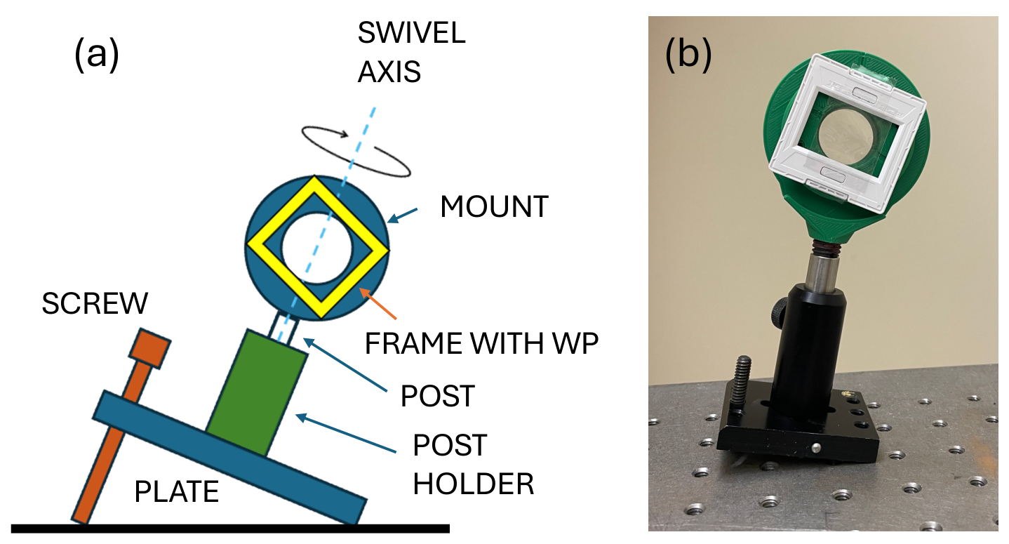
The swivel mount is easy to set up. As mentioned earlier, we used a 3D-printed mount that needed only one initial adjustment. We mounted it to a 0.5 in diameter post (with 1/4–20 set screws) to a post holder, but kept it loose on the post holder, so it could swivel. The post holder sits on a plate that can be tilted by adjustment of a screw located at one end of the base plate, as shown in
Figure 5.
The cellophane was mounted on a 35 mm slide frame, which was attached to the mount by double-sticky tape.
Figure 5 shows one of the waveplates on the tilted mount.
Appendix B.1 gives a step-by-step procedure to set up and orient the flip mount.
The point of the swivel mounts is to provide an easy way to switch between the binary settings of the optical elements. The use of tilted posts is our way to implement such a system, but other approaches using creative 3D printing elements
Haverkamp et al. (
2022) and
IQC (
2024) could also be adapted with this concept.
2.2.2. Setting the Basis: HV or DA
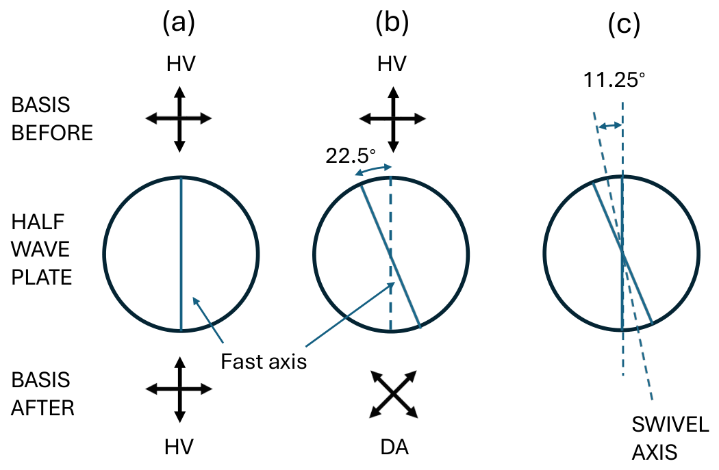
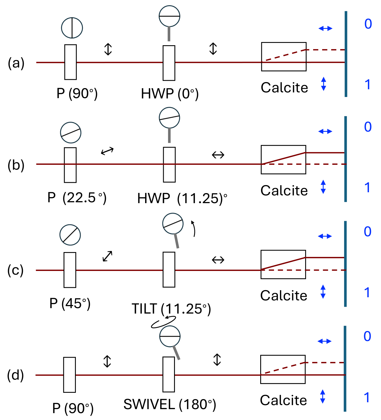
There are two basis adjustments. One is for Alice, and the other one is for Bob. Both are controlled by a tilted HWP. In the case of Alice, the basis waveplate is located after the first (state) HWP. If the axis of the HWP is
or
, the input polarizations, horizontal or vertical, are unchanged as shown in
Figure 6a. This is the HV-basis setting. If the axis of the HWP is set to
, then the horizontal state becomes diagonal, and the vertical becomes antidiagonal. This sets the polarization coding to the DA basis setting, as shown in
Figure 6b. By swiveling the HWP with fast axis vertical about a swivel axis tilted by
, as shown in
Figure 6c, we can switch the polarization between the HV and DA bases.
Appendix B.2 gives a step-by-step procedure to set up and orient the flip mount.
2.3. Mimicking Eve
As mentioned earlier, in a real situation with single photons, Eve must detect (destroy) Alice’s photon and resend a new one in the orientation found. So Eve has to pick a basis to detect Alice’s photon. If the base is the same as Alice’s, Bob gets a photon with the same orientation as Alice’s. A birefringent optical element with axis (fast or slow) aligned with the photon’s polarization will produce the same effect.
If Eve detects Alice’s photon with the wrong basis (i.e., at from Alice’s photon polarization), it will result in communication errors. Because Eve resends the photon in the state that is intercepted, it will result in sending Bob a photon polarized at to Alice’s polarization. However, the same outcome would be obtained with an optical element that transforms Alice’s polarization into one that, on average, produces an equal number of detections in Bob’s detectors (and therefore introducing errors the same way). We note that this only mimics Eve’s action, because in a real scenario with single photons, Bob would get a photon with either or from Alice’s photon orientation, due to the randomness of photon detections by Eve. However, for a demo that does not use single photons, Eve’s intrusion with the wrong basis produces equal intensities in Bob’s splitter.
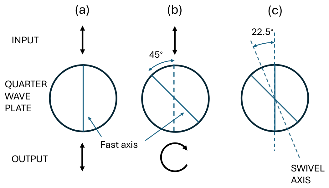
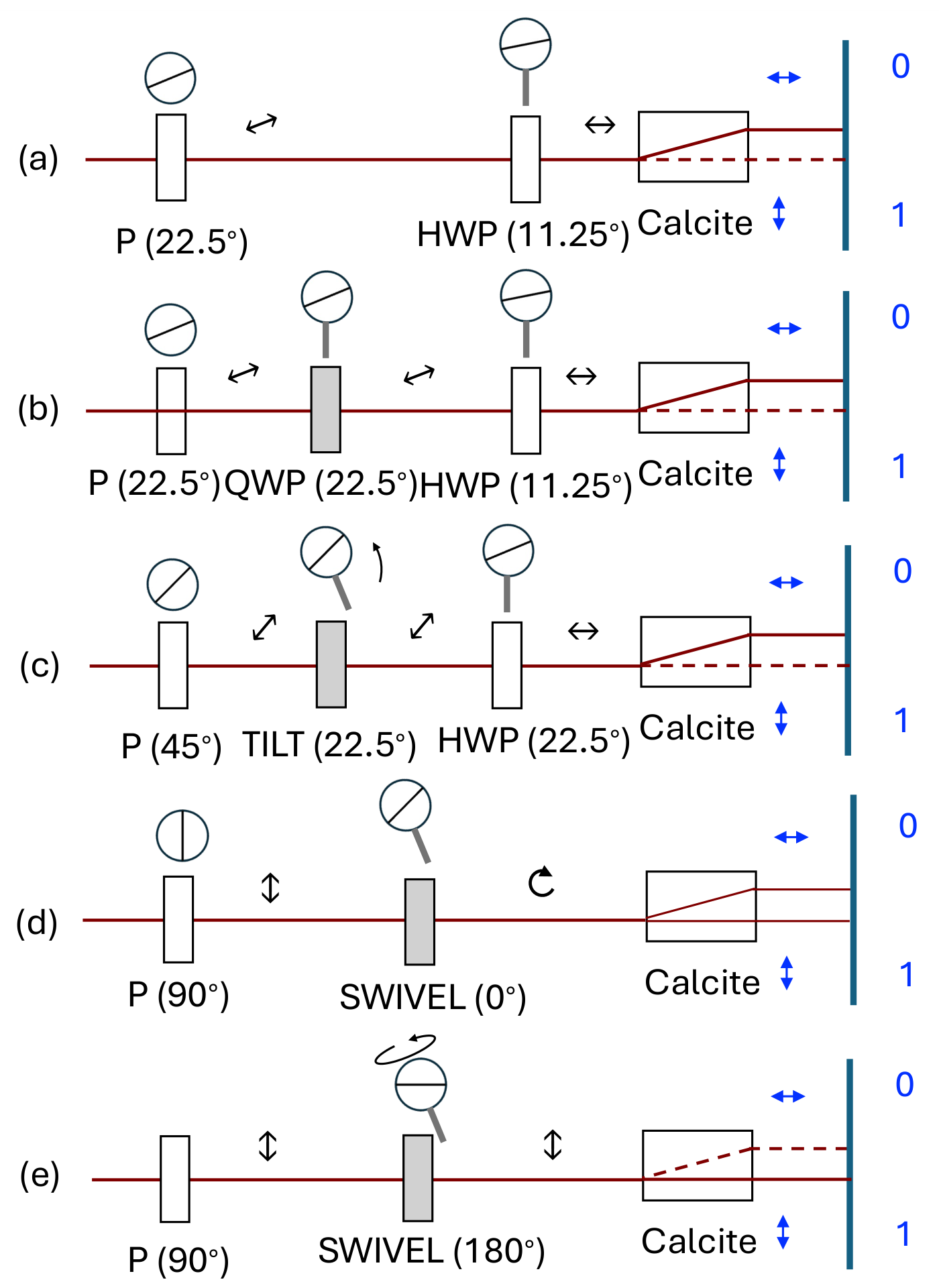
An optical element that would mimic Eve is a quarter-wave plate (QWP). When the axis of the QWP is aligned with Alice’s basis, it preserves Alice’s photon state (polarization). When it is at 45° to Alice’s basis, it converts the state into a circularly polarized state, producing equal detections on Bob’s detectors. This is shown in
Figure 7. A tilted QWP set up exactly as with Alice’s state encoder will do. This is shown in
Figure 7: in one position, it is aligned with either vertical or horizontal, and in the other swivel position, it is aligned with diagonal or antidiagonal. Because the cellophane HWP’s are double-ply, a single-ply works as a QWP.
Appendix B.3 gives a step-by-step procedure to set up and orient the flip mount.
3. Results
In the implementation of this protocol, we have four components with binary settings: Alice’s input state (0 or 1), and Alice’s, Bob’s, and Eve’s bases, horizontal–vertical (HV = +) and diagonal–antidiagonal (DA = ×). This entails 16 combinations total, which are summarized in
Table 1. The outcomes measured by Bob are listed as “0” (all the light leaving the 0 port), “1” (all the light leaving the 1 port), and “0/1” (half the light leaving through each port).
In possibilities 1–8, Alice and Bob have the same basis. In 1–4, Eve has the same basis as well, so Bob gets the same state as Alice, while Eve stealthily obtains the transmitted code. Cases 5–8 simulate Eve guessing incorrectly, measuring in a basis different from Alice and Bob’s. In this case, there is an equal chance that Bob will get a 0 or a 1. In possibilities 9–16, Alice and Bob have different bases, so regardless of Eve’s setting, Bob can get a 0 or a 1 with equal probability. In a real implementation, situations (9–16) get discarded after Alice and Bob compare their bases (but not the data) on a subset of transmissions. So we are left with possibilities 5-8, which are uncertain. Because there is equal probability for each outcome, on average, half the time the outcomes will agree with Alice, and half the time they will introduce errors. That is, two out of eight decodings will not agree with the input state, yielding a 25% error rate.
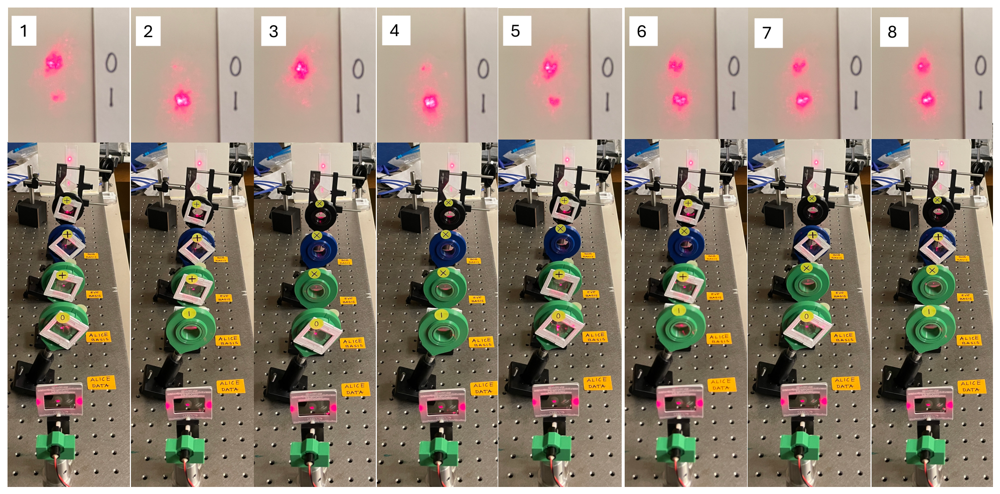
Figure 8 shows the visual outcomes of the first 8 cases of the table. The laser (<USD 20) is mounted on a 3D-printed mount atop pedestal mounts. It is followed by two stacked film polarizers to ensure that photons are vertically polarized. Next are four tilted swivel mounts holding the cellophane waveplates. The order of the waveplates is as specified in
Figure 1. The swiveled positions are indicated by the yellow labels and the position of the frame carrying the cellophane waveplate. A clear calcite crystal split the light by polarization, as shown on the screen.
In the demo, a “0” or “1 outcome will show a strong beam coming out of one port and zero or very little coming off the other port. When the outcome is labeled as “0/1”, the same amount of light will come out of both ports. If the HWP departs from ideal, the polarization transformation that it imparts will be imperfect. So, only in the case where the polarization remains unaltered by the HWP will the outcome be the cleanest. With our setup, where the input polarization is vertical (state 1), this situation corresponds to case 2. When the input state is 0, Alice’s state HWP rotates the polarization from vertical to horizontal. So, in case 1, the first HWP transforms the polarization, while the other three waveplates preserve the polarization orientation. Bob’s splitter does so in the HV basis, so when measuring in the HV basis, the HWP just preserves the polarization. This corresponds to cases 1 and 2. For cases 3 and 4, Bob’s HWP must rotate the polarization by
. Therefore, cases 3 and 4 will involve three and two transformations, respectively. As the state is modified by consecutive transformations, imperfections in the waveplate will accumulate error in the photon state, and increasingly reduce the contrast between 0 and 1. This can be seen in
Figure 8.
When Eve’s basis differs from Alice’s and Bob’s, Eve’s waveplate transforms the linear polarization into nearly circular polarization. Cases 6, 5 and 8, and 7 involve, respectively, 2, 3, and 4 transformations. Deviations from the intended transformation result in an unequal balance of intensities when the expectation is of an equal balance. As can be appreciated from the figure, despite imperfections, the visual output is consistent enough with the expectations, providing a simple demonstration of the quantum effect.
4. Implementation
What approach should we take to introduce students to this application? Quantum physics is abstract and counterintuitive, so a hands-on visual demo is a tangible reinforcement method. What is the context? In our case, it is an introductory college course for a general student audience with minimal mathematical preparation (algebra/trig) and no advanced knowledge. As such, it can easily be adapted to a K-12 activity teaching quantum physics. In our case, the course needs a scaffolding of concepts and mathematical artifacts to introduce students to quantum physics. Here, we will give a brief description within the context of the demo.
4.1. Preliminaries
The first level has to be a mathematical scaffolding that introduces the language of physics, such as numbers, units, symbols, etc. There has to be a discussion of classical vs. quantum. We did so by introducing atoms, light, and quantization. There are lots of demos related to light, and the line spectra of discharge lamps go a long way to illustrate quantization in atoms. Photons are introduced with the photoelectric effect. Although this topic has a number of subtleties, we only used it to connect it to detectors, such as cameras and solar cells. We did not discuss the photoelectric formula, as it introduced too many other concepts (voltage, current, work function, etc.) that would deviate from the central discussion.
Because the demo uses polarization, we introduced polarization via hands-on demos with polarizers and calcite crystals. This also served to introduce the types of polarization used: horizontal, vertical, diagonal, and antidiagonal. Once this was completed, we introduced the indeterminism of quantum physics. How do we predict which way the photon goes as it enters a calcite crystal? Here, we introduce probability, with exercises on classical probabilities (coin toss, etc.), but also introduce the inherent probability expounded by quantum physics. Many general texts introduce these ideas at an appropriate introductory level (
Raymer, 2017). We finished this section by adding the concept of no-cloning, which states that quantum states cannot be cloned. This starts to set up the application of QKD.
There is another preliminary that we embarked on before QKD: encryption. Although this is an unfamiliar topic for students, they find it fascinating. Thus, you can have students do an exercise on Caesar’s cipher and others (
Loepp & Wootters, 2006). At this point, we introduce the one-time pad with binary data and a key. Pairs of students are asked to come up with a random key. A sender creates a message and encodes it, he/she gives it to the partner, who then decodes it using the key. The method is simple: the message bits are added modulo-2 to the key bits one by one (also the exclusive-OR operation), and in decoding, the process is repeated, with the encryption key added bit-by-bit to the key, resulting in the original message.
4.2. Lab Activity 1: Photons and Calcite
A first activity with this demo is to use the setup of
Figure 1 with only the first and last components (Alice’s data HWP and Bob’s calcite and screen). In this activity, students recognize the clear outcomes for horizontal and vertical polarization, the same as outcomes #1 and #2 in
Table 1 and
Figure 8.
Following, Alice’s basis HWP is added. In one setting (+), it preserves the H and V polarizations; in the other (×), it flips them to D and A, respectively. When selecting the + basis, outcomes are the same, but when selecting the × basis, the outcomes are different: equal intensities on both spots on the screen (the outcomes are consistent with rows # 9 and # 10 of
Table 1). Here, we must introduce how such an outcome is related to polarization. Since the initial intensity is
, where
is the number of photons in the beam, then the final intensity at each port is
, where
P is the corresponding probability. HV photons are detected in the × basis with
, so
.
A third step is to add Bob’s basis selector and repeat the exercise with Alice sending photons in the + basis and Bob detecting in the × basis (for which case ). A fourth step would be to let students figure out that when Alice and Bob have the same basis, the outcomes are clear.
4.3. Lab Activity 2: Simulating Communications
In the context of sending and receiving information, students could be asked to develop a communication system using 0’s and 1’s (we need to let students do something for themselves). They may associate the binary data with polarization in different ways than done here, but that is okay. The convention is up to the users. At this point, students will realize that communication is transmitted without errors only when Alice and Bob share the same basis. Students can be challenged to generate a key using this system.
4.4. Lab Activity 3: Introducing Eve
Eve uses the detect and resend approach in an attack on the communication. Because Eve resends the state she measured, if her basis differs from Alice’s or Bob’s, the data she sends contains errors in 50% of the detections. The use of the quarter-wave plate only mimics the consequence of Eve’s intrusion. However, it is a simple way to do so. The final step in this demo is for students to verify
Table 1. Students can be challenged to determine whether Eve is present in the communication (by concealing Eve behind a box or screen).
5. Conclusions
This project grew out of the desire to offer a hands-on experience to illustrate QKD to a general population of first-year college students taking a first-year seminar on quantum physics at Colgate University. With students having no prior experience with optical equipment or hardware, the demo had to be easy to use and simple to understand, without distracting them with the equipment’s details. The desire to set up several demos required the use of inexpensive parts. The 3D-printed parts and cellophane waveplates made such objectives possible. The design and testing of the apparatus took too long for the demo, as presented here, to be implemented in the course. Students were still exposed to the indeterminism of quantum physics via polarizers and calcite crystals. The section on QKD, which was part of the course, gave students a new perspective on quantum physics. Their preconception was that the topic could be esoteric, difficult, and unapplicable. In the end, they found the material interesting, understandable, and relatable to their everyday lives: students use cards and phones to make purchases, which require encryption to protect against hacking or theft.
The design of the equipment for this project aimed to be simple and inexpensive enough to be feasible to implement in the high-school setting, where budgetary constraints are high. The student population should not be too distinct from the college group for which this demo was aimed. The main components of this demonstration are all inexpensive, with a red laser pointer as the source, cellophane from wrappers, calcite crystals from museum shops, and 3D-printed hardware, only needing instructor time to put the parts together and set them appropriately as described in this article.
We also tested the apparatus with two other sets of waveplates. One was a set of film half-wave plates that, unfortunately, are no longer commercially available, which worked well at 670 nm. A second test involved using a HeNe laser with four commercial zero-order waveplates corresponding to the laser wavelength, which worked very well and served as a proof of principle for our scheme.
The demo illustrates a fundamental principle of quantum physics. Even if we do not use single photons, many photons yield a statistical outcome consistent with the main physics principle. When the detection probability is 0.5, we detect light beams at half intensity. The demo is not intended to demonstrate a single-photon event. Lasers are in a coherent superposition of photon states, so quantum rules still apply. Conversely, by showing intense beams of light following the quantum principles and QKD arguments, the demo constitutes a vivid display of quantum physics in action.