Article

Automatized Evaluation of Students’ CAD Models

Faculty of Mechanical Engineering and Naval Architecture, University of Zagreb, 10000 Zagreb, Croatia
*
Author to whom correspondence should be addressed.
Educ. Sci. 2021, 11(4), 145; https://doi.org/10.3390/educsci11040145
Submission received: 15 February 2021 / Revised: 11 March 2021 / Accepted: 22 March 2021 / Published: 24 March 2021
(This article belongs to the Section Technology Enhanced Education)

Abstract

:
The article describes an attempt to address the automatized evaluation of student three-dimensional (3D) computer-aided design (CAD) models. The driving idea was conceptualized under the restraints of the COVID pandemic, driven by the problem of evaluating a large number of student 3D CAD models. The described computer solution can be implemented using any CAD computer application that supports customization. Test cases showed that the proposed solution was valid and could be used to evaluate many students’ 3D CAD models. The computer solution can also be used to help students to better understand how to create a 3D CAD model, thereby complying with the requirements of particular teachers.

1. Introduction

One of the essential tools in any mechanical engineer’s arsenal of knowledge is using a computer-aided design (CAD) software application. In recent years, we have observed the increasing prevalence of mass education and the growing relevance of geometric modeling and CAD skills and competencies for graduates of technical and engineering colleges [1,2,3], pushing CAD courses into the undergraduate programs of many universities. Traditionally, CAD instruction has focused on teaching students the skills they need to build a particular geometrical model in a particular CAD package. Dutta and Haubold [4] noted that “introductory courses are imperative for first-year engineering students to become interested in engineering. These courses must be designed to accommodate students with diverse interests and technical backgrounds while introducing students to engineering design related to their educational careers. This is important because basic design skills are important to all areas of engineering design”. On the other hand, Carberry and McKenna [5] reported, in a preliminary study including but not limited to CAD models, that engineering students do not develop a comprehensive understanding of the capabilities and benefits of modeling.
The theme described in this article can also be used in other fields of engineering such as electrical engineering [6], architecture [7], cartography [8], or geography [9]. The basic requirement is the usage of a feature-based design (FBD [10]) approach. In some cases, the proposed data model should be adopted to specific needs.
In the Faculty of Mechanical Engineering and Naval Architecture at the University of Zagreb, one of the first-year courses involves computer-aided design. This course teaches students the basics of working in the SolidWorks CAD environment and the theoretical principles needed to understand how CAD applications work (with particular emphasis on feature-based design). The one-semester course enrolls approximately 600 students (each year) divided into 40 groups of 15 students. A total of 25 teaching assistants teach the tutorials. The aim of this course is for students to learn the fundamentals of creating parts and assemblies, as well as the technical documentation.
There has been a rising tendency in teaching CAD modeling to shift the perspective from procedural knowledge to strategic knowledge when teaching students how to build FBD CAD models [11]. Indeed, from a pedagogical perspective, researchers agree that strategic knowledge should be a fundamental part of teaching solid modeling [12,13]. Unfortunately, due to the number of students and limited time for tutorials, our curriculum focuses on procedural knowledge. Of course, this does not mean that students are left with only the procedural knowledge they have acquired. Developing strategic knowledge and modeling students’ skills within the CAD competency are a part of the senior year curriculum.
Most students start learning and exercising shortly before the examination; however, such an approach leads to inadequate preparation between the tutorials. To encourage them to work continuously, we introduced a short test to be administered at the beginning of each tutorial. In these short tests, students must show that they have mastered the matter from the previous tutorials. Each short test is graded by the teaching assistant immediately following the end of the test. Teachers have approximately 10 to 15 min to assess and grade all students’ work. This can lead to the teacher overlooking some good or poor student solutions due to insufficient grading time. Other researchers have also recognized this problem. Otto et al. [14] stated that “in the context of CAD mechanical engineering education (MCAD), the assessment of CAD models is a rather delicate and very time-consuming activity that requires, among many other competencies, the ability to distinguish between trivial errors efficiently, i.e., errors committed by students due to carelessness and inattention during the execution of the exercise, and more serious errors, i.e., errors that occurred due to a lack of knowledge and understanding of the subject”. To help both students and teachers, we started developing a computer program solution to automatically evaluate student CAD models.
The automatized evaluation of model files has long been a goal to decrease teachers’ overall time when evaluating a large number of student models, thus shortening the time until students receive feedback after they submit their work, as well as allowing a quantitative evaluation of model quality.

2. Literature Overview

At engineering universities worldwide, the use of at least one 3D CAD program application is one of the basic skills that all students majoring in engineering, design and related subjects must master. CAD skills are obtained at multiple levels, from grasping the commands and how the CAD application works (procedural knowledge) to understanding the design intent and the ways to create 3D models (strategic knowledge). Regardless of which level of instruction is introduced, one problem remains: assessing student work objectively. Hamade, Retail, and Jaber [15] proposed an indirect measurement method that measured the time spent constructing the model (including time spent undoing and redoing actions). The number of construction feature measurements was based on the number of features used. In this context, using the least number of features would be considered the best performance. They suggested that, if students could complete the model with the fewest number of features and in the shortest possible time, this would be a demonstration of their knowledge.
On the other hand, Otto et al. [14] stated that the emphasis when teaching parametric associative feature-based CAD software is on model construction strategies that combine a reasonable number of features with a fast completion time, rather than aiming for the smallest possible number of features. Some efforts to address the problem of assessing student work have focused on building computer program solutions. To evaluate SolidWorks files, Baxter and Guerci [16] developed a computer program to automate the process. Their program compares crucial data from student files against the correct ones. Their published work did not reveal any information about grading algorithms or findings [17].
In his paper, Kirstukas [17] outlined computer programs for automatic grading of geometry and the ability to remain correct if the solid model is changed. The main feature of the program (Figure 1) is that it is written primarily for Simens NX and can be executed within the CAD application. The graphical user interface (GUI) shows 12 different deduction categories, and the teacher can set the ones they want to be checked. The “gold standard” model is used as a basis for comparison against student model files.
According to the author, some problems were encountered during testing. The method is most useful at distinguishing decent and good models from the best models. Student models with significant problems may get lower scores than a blank model if they have sufficient unconstrained sketches, unwanted/repeated/missing dimensions, and so on. The author’s approach also changed some feature dimensions to better assess the model’s integrated “design intent”. Ault and Fraser [18] described a program to automate the evaluation of CREO (PTC Parametric Technology Corporation). The teacher’s file is used as the reference for comparison against the student file. The information compared is the model volume, as well as the overall number of extrusions, holes, and patterns, focusing on the presence or lack of important dimensions. The main difference with Kirstukas’s approach is the absence of an evaluation of the model’s changeability.
A very different but interesting approach—that of rubrics (Company et al. [19,20])—has also been used to evaluate student CAD models. The main disadvantage of using rubrics in assessing student work is the very long time it takes to return an answer when there are many students. Teachers must open and interpret each student model and complete the rubric sheet, which takes time. Even if the implementation of rubrics is well thought out, a quick assessment of CAD models is not possible. This approach is more appropriate when there is a smaller number of students, and when the assessment does not need to be completed in a short period. However, for student self-assessment, this is a very good method.
The most recent research in addressing the problem of evaluation or assessment of student work includes the studies by Garland and Grigg [21] and Ambiyar et al. [22]. Garland and Grigg, in their work, compared grading done by the teacher and grading done by the computer program. The computer program used in their research was a commercially available program called Graderworks (which can be downloaded free of charge for noncommercial purposes). Graderworks was developed specifically for SolidWorks, and a data model is not available. Graderworks implements rubrics and reads the native SolidWorks file format. However, the teacher has limited options in terms of configuring how the program will work and cannot extend rubrics or any other part of the program. Although this approach looks promising, it lacks the ability to be implemented with any commercially or non-commercially available CAD program application, and the rules (rubrics) used for evaluation can’t be easily tailored for a specific purpose. Ambiyar et al. used rubrics for student work assessment, but they focused on two-dimensional (2D) CAD models. Students do not use features (FBD) in these cases; thus, the assessment is done using the “assessment for learning” approach through observations (two cycles) and meetings at the end of each cycle. Specifically, the teachers observe student learning activities through inspection sheets, while student learning results are graded using objective test tools.

3. Automatized CAD Models Evaluation Program Solution

A review of current approaches to evaluation of student CAD work showed that existing approaches and models are not adequate to address the problem of rapidly evaluating a large number of CAD models. However, valuable insights can be drawn from them. To better understand the actual steps of the evaluation process and learn about teachers’ expectations for such a program, several interviews were conducted. The interviews (Table 1) were conducted with teachers who teach CAD modeling to students. The interviews each consisted of two questions and were conducted with seven teachers. During the interviews, teachers were asked to describe how they evaluate student work and what they think a computer program should do to help them.
After analyzing their responses, it became clear that teachers examine the model down to the sketch level when evaluating it. They do not check all the coordinates, but they check the overall size of the model (the envelope) and “standard” model properties such as the material, volume, units, and sometimes the center of inertia. They emphasized that, depending on the modeling lesson, certain features must be used in the model, but they generally do not insist on their order. The teachers stated that the computer application must use its own rules for evaluation and that they must be able to create different sets of rules for different lesson outcomes, even when the same model assignment is used. They also require the computer program to be capable of bulk evaluation and student self-evaluation. From the authors’ experience and teacher responses, the following requirements for the computer program were defined:
  • The computer program solution must assist teachers in evaluating student CAD models, both individually and in bulk.
  • The computer program solution must be suitable for implementation in various CAD applications.
  • The computer program solution must support students in self-evaluation of CAD models.
  • The computer program solution must allow teachers to define their evaluation criteria.
  • The computer program solution must be simple enough for students to use.

4. Scenarios

The analysis of teacher interviews led to several scenarios. The basic scenarios are described below.
  • From the teacher’s point of view:
    First, the teacher creates a 3D FDB model that is given to the students as an assignment.
    The teacher exports the 3D FDB model to an XML-structured file.
    This exported XML file is used as a basis for the creation of the rules that are used to evaluate the student models.
    During rule creation, the teacher can select which elements of the FBD model must be present in the student model and the number of points to be assigned if the condition is met. The teacher has several options to define the condition evaluation:
    EXACT—the value of the element from the student model must exactly match the default.
    DISCRETE—the value of the student model element can match any of the predefined values.
    TOLERANCE—the value of the student model element may vary within specified tolerance values.
    RANGE—the value of the student model element can take any value within a specified range.
  • From the student’s point of view:
    The student creates a 3D FBD model of the product (Figure 2), and then selects the command to evaluate their work (the command is a part of the CAD application interface or a macro).
    In the command initialization, the student can select the teacher’s reference model to evaluate their model.
    After the command is initiated, the CAD module exports the 3D FBD model to an XML-formatted file and sends it to the evaluation engine.
    The evaluation engine evaluates the XML file using the teacher’s reference model and generates a report file for the student to read.
    Lastly, the report file is displayed to the student.

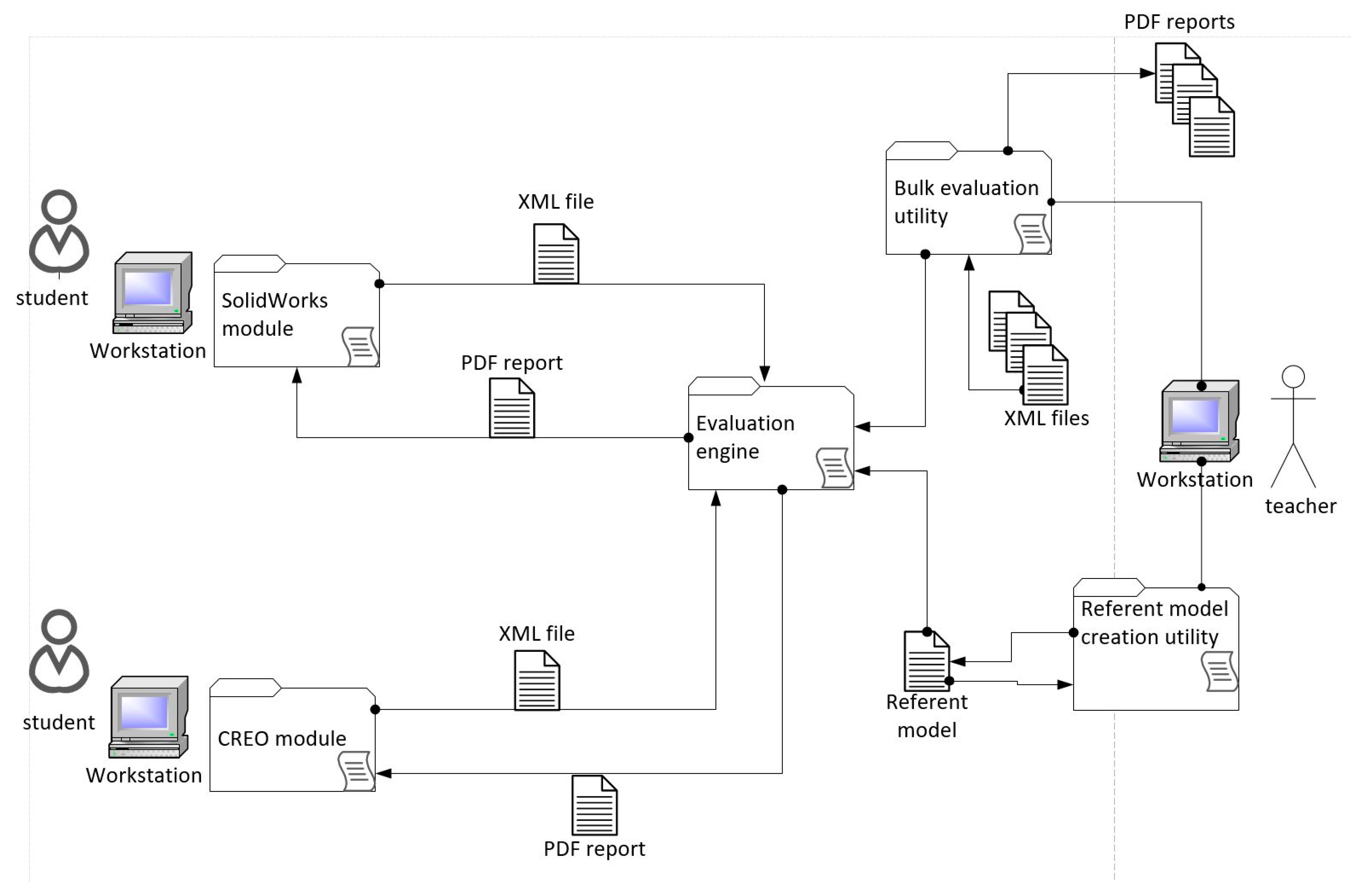
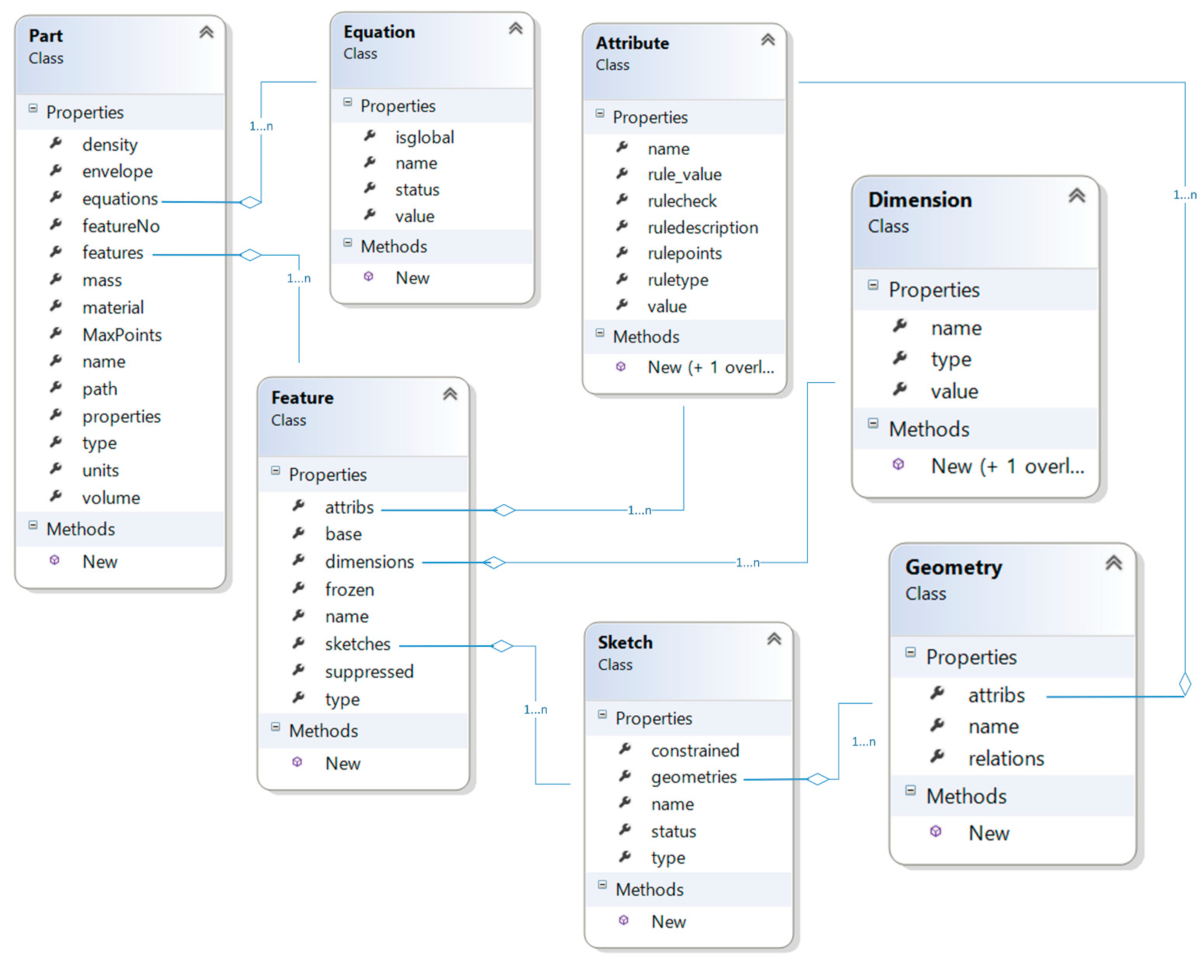
5. Basic Concept and Data Model

Based on the data described in the previous section, the basic architecture for the computer program solution was designed. The computer program solution (Figure 3) consisted of multiple parts, as outlined below.
  • Computer program solution modules:
    CAD model export module.
    Evaluation engine.
  • Additional utilities:
    Bulk CAD model export utility.
    Bulk CAD model evaluation utility.
    Reference model creation utility.
CAD modules are native to the CAD application used for model generation, and they are written in an application programming interface (API) available for the particular CAD application. For our prototype implementation, we used the SolidWorks application and its API. The developed CAD module can be executed from the SolidWorks toolbar like any other command. The evaluation engine reads the CAD module data and generates a student report based on the evaluation results. The referent model creation utility creates rules for the evaluation of the student model. When teachers want to simultaneously evaluate many student models, the bulk utility can be used.
After analyzing the 3D CAD FBD model information and the aspects identified as those that the teachers examine in each model to better understand what students have done, the data model was created (Figure 4).
From the class diagram in Figure 4, it is clear that the data model does not capture all the information available in the FBD model, but only the information that is sufficient to reflect what teachers are looking for and evaluating in the student model. A challenge when designing the data model was that different CAD applications define the FBD element using different sets of information. That is why what can be achieved using the CAD FBD model depends on the available API. Almost all APIs for CAD applications give the user the ability to extract a basic dataset from the model. For extensive data mining, a commercial API license should be purchased.
The user input screens of the computer program for general data and feature data are shown in Figure 5 and Figure 6, respectively.

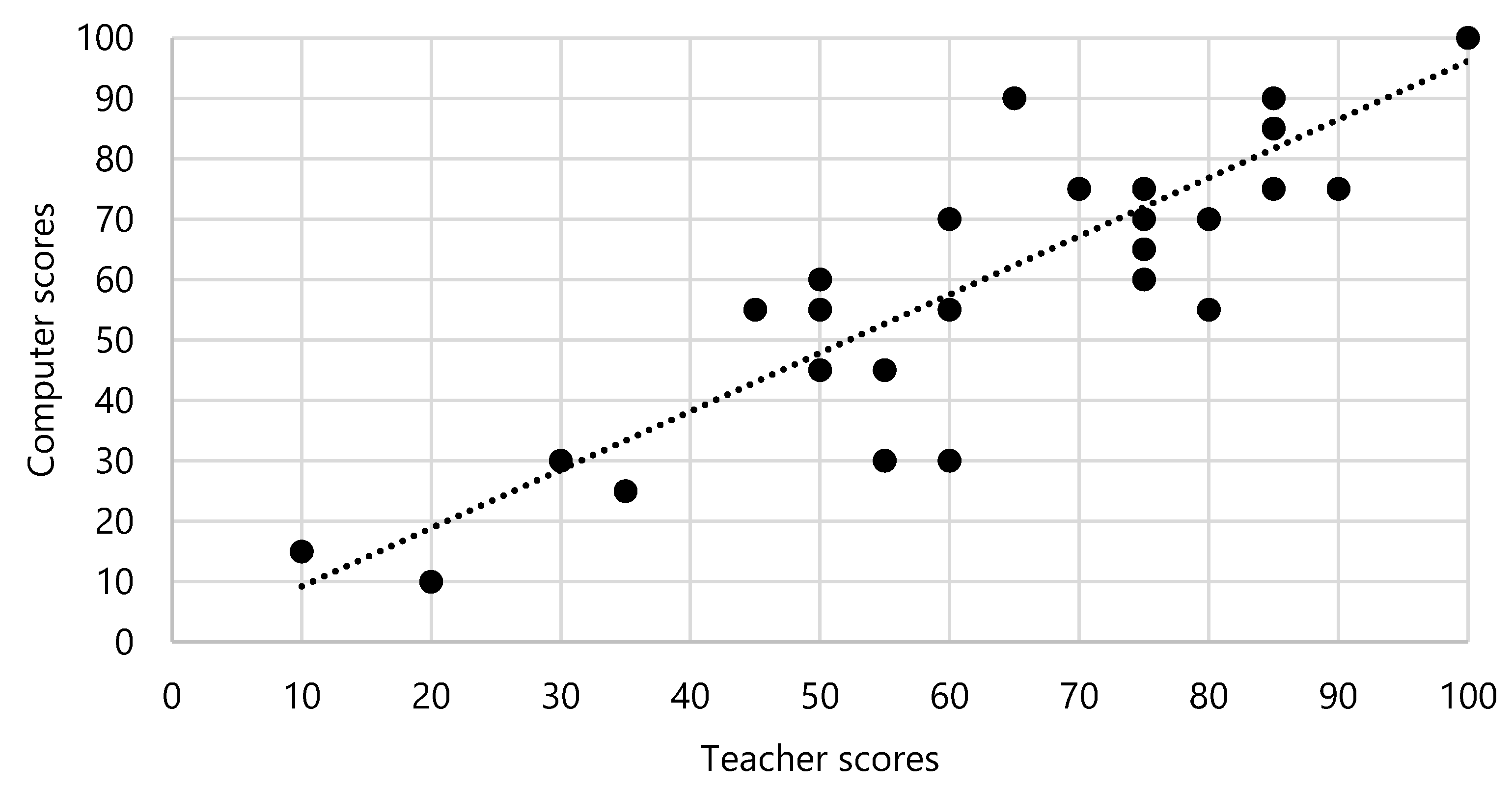
6. Preliminary Testing Results

Before discussing the evaluation process and the results, it should be noted that this is a work in progress. What is described in this paper is a prototype computer program and not a final product. After the prototype computer program has been evaluated, the professional programmers will create the final product. The prototype computer program was evaluated in two parts. The first part involved evaluating the students’ models, which teachers have traditionally evaluated. The second part involved giving a group of students the task of evaluating their models themselves and providing feedback.
For the first part, the students’ models were sampled from a pool of models created by two groups of students that attended an introductory CAD course in the previous academic year. Throughout the semester, each group had been given a total of 12 modeling assignments. With an average of 15 models per group (14 student models and one teacher model as a reference), the model database used in this preliminary study consisted of approximately 360 models. However, only two assignments were tested as part of the preliminary testing. These testing results are shown below.
It should also be noted that both groups had the same teacher. The teacher was asked to pick only those rules that they would evaluate in the traditional approach and assign an appropriate number of points. The same teacher evaluated the corresponding models in the previous academic year. The model created by the teacher was used as a reference model to verify that the tool could correctly identify all selected attributes. Hence, the teacher’s models (reference models) were also included in the analysis.
The comparison of the evaluation data performed by the teacher (during the previous academic year) and the computer program (based on the teacher’s criteria) is shown in Table 2. A more detailed presentation of the test cases is shown in the Appendix A.
A more detailed insight into the data can be given by analyzing the correlation between the scores provided by the teacher and the scores calculated by the computer application. A scattered plot of all the scores from Table 2 is shown in Figure 7.
Pearson’s test was used to quantify the correlation between the two sets of scores, since the normality, the homoscedasticity, and the linear relationship can be assumed for this type of data. The Shapiro–Wilk test was used to test the data for normality, and the normality assumption was not rejected at the significance level of 0.05. Therefore, Pearson’s test was selected as the most appropriate tool for this specific purpose.
A very strong positive correlation (r = 0.867) was found between the teacher and computer scores at the significance level of 0.05. Such a result suggests that, according to the preliminary tests, the computer application has a strong potential to support, or even replace, the human evaluator.
The second computer program assessment involved five students. Their task was to create a model based on a given drawing. After the students completed their tasks, they were interviewed and asked about their observation of the evaluation process and the resulting report. Overall, all the students appreciated the computer application for self-evaluation. They indicated that the computer application helped them better under-stand how the models were evaluated and how to improve their models. The students also stated that the current evaluation process was somewhat confusing because students had to download the rules file from Moodle, set up the computer application, and then launch the application and find the PDF file to review the result. These problems will be addressed in the final computer program version.
The teachers who were asked to create rules for the computer application had some suggestions to improve the computer application. The suggestions were:
  • The teacher needs to be able to define grading levels. For some student tasks, it is enough to score the model at the feature level; for others, it would be useful to score the model at the sketch geometry or geometry property level (coordinate level).
  • It would be a good option to have some visual aids when assigning points to elements so that the teacher has a preview of the assigned points.

7. Discussion

The presented approach for automated evaluation of students’ CAD models builds on existing ideas of using a computer program coupled with a CAD application to evaluate CAD models [13] in comparison to a reference model [14] created by a teacher, with the addition of grading rules based on that particular reference model. The proposed approach was conceptualized for fast evaluation of student CAD models during teaching sessions. It enables repeatable and objective evaluation, which reduces the time needed for grading and leaves more time for the teacher to spend on teaching [16]. The developed prototype and its preliminary testing have demonstrated several of the benefits of using the proposed evaluation approach, but also a few problems that need to be addressed in future work.
The results of the conducted experiment evaluation can be compared with the results of existing approaches [13], and a similar correlation between teacher and computer assessment can be observed (Figure 7). The very strong correlation of assessment indicates the approach’s potential as a suitable tool for the automated evaluation of students’ CAD models. The students can also use the proposed approach for self-assessment in preparation before lectures or exams. In future development, the approach can be used for a distance learning (i.e., online) CAD modeling course, similarly to the approach proposed by Jaakma and Kiviluoma [23]. Another benefit of the approach is the reduced subjectivity in evaluation. While teachers typically do not consider and score all the correct aspects of the model, nor can they always detect all the mistakes, the computer program consistently awards or subtracts points for each item according to the reference model rules. From the data analysis, it is evident that, for some students, the final score was off by more than 20%, which might have been due to the subjective nature of the evaluation process when conducted by a teacher. In most cases, the difference was no more than 10%, which is acceptable at this stage of development.
On the other hand, the proposed approach and developed prototype had certain drawbacks that need to be addressed. The method was developed to evaluate FBD CAD models with a prototype developed for Dassault’s SolidWorks part models. While the method can be transferred to other areas of CAD design, the prototype would need to be recreated for each specific software. Another potential issue is the problem of evaluating the student’s design intent. Currently, the approach evaluates the correctness of features and dimensions based on the reference model and rules created by the evaluator. Thus, a student can recreate the correct geometry but use different feature types (e.g., instead of using the sweep feature to create geometry, using a revolve or loft feature) or they can use a different number of features to get to the same final geometry. The design intent of using one feature instead of another could not be evaluated at the present stage, and students could thus score lower if the feature set up by the grading rule was not used. In the conducted experiment, the problem was not significant as the modeling task was short, utilizing only a few features, mostly from the previous tutorial, and students were told to use certain types of features. Nevertheless, the design intent differences could be significant in more complex models. The same issue was reported by Baxter and Guerci [16] who specified the grading criteria in a given task to reduce the number of incorrect grades. Additionally, they reported the side benefit of students’ clearer understanding of what is expected of them in the modeling task when given these supplement descriptions. Similar grading criteria could be applied in the proposed approach as well.
Similarly, the application could assign points to the student even if they received a poor grade overall. For example, if the student created the correct model type, assigned the correct file name, selected the right material but did not create any features, the application would award them points, whereas the teacher would most often not. Furthermore, the program could detect sketches that were not fully defined but cannot deduce whether the problem stemmed from the construction geometry—that is, the secondary geometry used only for more efficient use of the sketching tool. Hence, grades may have been lower even when a minor mistake was made (e.g., student did not define the length of the symmetry line).
Another problem encountered during the testing was the teacher’s need to do several iterations to create rules that best reflect their own scoring process when evaluating the students’ models. While this is a time-consuming process during setup, it reduces the time needed for evaluation. Also, it is expected that the evaluators (teachers) will be more efficient at setting up the automatic evaluation once they familiarize themselves with the overall approach and the computer application. Nevertheless, additional visual aids for setting rules are planned to be implemented.

8. Conclusions

Achieving fast and objective evaluation of student CAD models was the driving motivation for creating the computer program presented in this article. The described approach showed its flexibility in integrating with different CAD applications and in preserving the teacher’s approach in the evaluation of student assignments. The major problem during the evaluation by the computer program prototype was the way in which teachers traditionally evaluate student work. The level of subjectivity that was involved in each case could not be determined. Furthermore, the granularity of the available information related to the parts, features, and sketches could lead the teachers to change their views when evaluating CAD models. The described computer program prototype showed objectivity in evaluating student CAD models, as well as rigidity in deciding whether to reward a student with points when they fulfilled a particular rule. For the next phase of computer program evaluation, the teachers suggested using the application as a guideline for the evaluation, but not as a final solution. As pointed out by the teachers, an issue that has to be addressed in the future development of the computer application is the problem with mentally connecting a rule to the particular element of a part, feature, or sketch. Some visual aids should be introduced.

Author Contributions

Conceptualization, N.B. and D.Z.; methodology, T.M. and F.V.; software, N.B.; investigation, N.B.; validation, T.M. and F.V.; resources, D.Z.; data curation, T.M.; writing—review and editing, N.B. and T.M.; visualization, T.M.; project administration, N.B. All authors have read and agreed to the published version of the manuscript.

Funding

This research received no external funding.

Institutional Review Board Statement

Ethical review and approval were waived for this study, due to anonymity of the subjects.

Informed Consent Statement

Subject consent was waived due to the omission of their names so the involved persons are anonymous.

Data Availability Statement

Conflicts of Interest

The authors declare no conflict of interest.

Appendix A. Test Cases

Appendix A.1. CASE 1

Computer program criteria:
  • Length, width, and height (tolerance ±10%).
  • Volume (tolerance ±10%).
  • One extrude feature (exact).
  • One cut extrude feature (exact).
  • One sweep feature (exact).
  • One mirror feature (exact).
  • Three fully constrained sketches (exact).
Table A1. First case—simple part.
Model CreatorScore by TeacherScore by Computer ProgramModel View
Teacher100100 Education 11 00145 i001
Student 15545 Education 11 00145 i002
Student 23525 Education 11 00145 i003
Student 35045 Education 11 00145 i004
Student 49075 Education 11 00145 i005
Student 58590 Education 11 00145 i006
Student 67565 Education 11 00145 i007
Student 77570 Education 11 00145 i008
Student 85530 Education 11 00145 i009
Student 96590 Education 11 00145 i010
Student 106030 Education 11 00145 i011
Student 113030 Education 11 00145 i012
Student 126590 Education 11 00145 i013
Student 132010 Education 11 00145 i014
Student 148575 Education 11 00145 i015

Appendix A.2. CASE 2

Computer program criteria:
  • Length, width, and height (tolerance ±10%).
  • Volume (tolerance ±10%).
  • Two extrude features (exact).
  • Three cut extrude features (exact).
  • One rib feature (exact).
  • One circular pattern feature (exact).
  • One chamfer feature (exact).
  • One fully constrained sketch (exact).
Table A2. Second case—complex part.
Model CreatorScore by TeacherScore by Computer ProgramModel View
Teacher100100 Education 11 00145 i016
Student 16070 Education 11 00145 i017
Student 24555 Education 11 00145 i018
Student 38070 Education 11 00145 i019
Student 48590 Education 11 00145 i020
Student 58585 Education 11 00145 i021
Student 67575 Education 11 00145 i022
Student 77560 Education 11 00145 i023
Student 88055 Education 11 00145 i024
Student 95060 Education 11 00145 i025
Student 107075 Education 11 00145 i026
Student 115055 Education 11 00145 i027
Student 126055 Education 11 00145 i028
Student 131015 Education 11 00145 i029
Student 14100100 Education 11 00145 i030

References

  1. Adnan, M.F.; Daud, M.F.; Saud, M.S. Contextual Knowledge in Three Dimensional Computer Aided Design (3D CAD) Modeling: A Literature Review and Conceptual Framework. In Proceedings of the International Conference on Teaching and Learning in Computing and Engineering, Kuching, Malaysia, 11–12 April 2014; pp. 176–181. [Google Scholar] [CrossRef]
  2. Chester, I. 3D-CAD: Modern technology—Outdated pedagogy? Des. Technol. Educ. Int. J. 2007, 12, 7–9. [Google Scholar]
  3. Hartman, N.W. Integrating surface modeling into the engineering design graphics curriculum. Eng. Des. Graph. J. 2006, 70, 16–22. [Google Scholar]
  4. Dutta, P.; Haubold, A. Case studies of two projects pertaining to information technology and assistive devices. In Proceedings of the 37th Annual Frontiers In Education Conference—Global Engineering: Knowledge Without Borders, Opportunities Without Passports, Milwaukee, WI, USA, 10–13 October 2007; pp. T2J9–T2J14. [Google Scholar] [CrossRef]
  5. Carberry, A.R.; McKenna, A.F. Analyzing engineering student conceptions of modeling in design. In Proceedings of the 2011 Frontiers in Education Conference (FIE), Rapid City, SD, USA, 12–15 October 2011; pp. S4F1–S4F2. [Google Scholar] [CrossRef]
  6. Shah, J.J.; Mäntylä, M. Parametric and Feature-Based CAD/CAM: Concepts, Techniques, and Applications; John Wiley & Sons: New York, NY, USA, 1995. [Google Scholar]
  7. Bullingham, P.J.M. Computer-aided design (CAD) in an electrical and electronic engineering degree course. In CADCAM: Training and Education through the ’80s; J.B. Metzler: Stuttgart, Germany, 1985; pp. 69–75. [Google Scholar]
  8. Aouad, G.; Wu, S.; Lee, A.; Onyenobi, T. Computer Aided Design Guide for Architecture, Engineering and Construction; Routledge: London, UK, 2013. [Google Scholar] [CrossRef]
  9. Edler, D.; Keil, J.; Wiedenlübbert, T.; Sossna, M.; Kühne, O.; Dickmann, F. Immersive VR Experience of Redeveloped Post-industrial Sites: The Example of “Zeche Holland” in Bochum-Wattenscheid. KN J. Cartogr. Geogr. Inf. 2019, 69, 267–284. [Google Scholar] [CrossRef] [Green Version]
  10. Smaczyński, M.; Horbiński, T. Creating a 3D Model of the Existing Historical Topographic Object Based on Low-Level Aerial Imagery. KN J. Cartogr. Geogr. Inf. 2020, 1–11. [Google Scholar] [CrossRef]
  11. Ault, H.K.; Bu, L.; Liu, K. Solid Modeling Strategies—Analyzing Student Choices. In Proceedings of the 2014 ASEE Annual Conference & Exposition, Indianapolis, IN, USA, 15–18 June 2014. [Google Scholar] [CrossRef]
  12. Menary, G.H.; Robinson, T.T. Novel approaches for teaching and assessing CAD. In Proceedings of the International Conference on Engineering Education ICEE2011, Madinah, South Arabia, 25–27 December 2011; pp. 21–26. [Google Scholar]
  13. Rynne, A.; Gaughran, W. Cognitive modeling strategies for optimum design intent in parametric modeling (PM). Comput. Educ. J. 2008, 18, 55–68. [Google Scholar] [CrossRef]
  14. Otto, H.; Mandorli, F. Surface Model Deficiency Identification to Support Learning Outcomes Assessment in CAD Education. Comput. Des. Appl. 2018, 16, 429–451. [Google Scholar] [CrossRef]
  15. Hamade, R.; Artail, H.; Jaber, M.Y. Evaluating the learning process of mechanical CAD students. Comput. Educ. 2007, 49, 640–661. [Google Scholar] [CrossRef]
  16. Guerci, M.; Baxter, D. Automating an Introductory Computer Aided Design Course To Improve Student Evaluation. In Proceedings of the ASEE Annual Conference, Nashwille, TN, USA, 22–25 June 2003. [Google Scholar] [CrossRef]
  17. Kirstukas, S.J. Development and evaluation of a computer program to assess student CAD models. In Proceedings of the ASEE Annual Conference and Exposition, New Orleans, LA, USA, 26–28 June 2016; Volume 2016. [Google Scholar] [CrossRef] [Green Version]
  18. Ault, H.K.; Fraser, A. A comparison of manual vs. Online grading for solid models. In Proceedings of the ASEE Annual Conference and Exposition, Atlanta, GA, USA, 23–26 June 2013. [Google Scholar] [CrossRef]
  19. Company, P.; Contero, M.; Salvador-Herranz, G. Testing rubrics for assessment of quality in CAD modelling. In Proceedings of the Research in Engineering Education Symposium, REES 2013, Putrajaya, Malaysia, 4–6 July 2013; pp. 107–112. [Google Scholar]
  20. Company, P.; Contero, M.; Otey, J.; Plumed, R. Approach for developing coordinated rubrics to convey quality criteria in MCAD training. Comput. Des. 2015, 63, 101–117. [Google Scholar] [CrossRef]
  21. Garland, A.P.; Grigg, S.J. Evaluation of humans and software for grading in an engineering 3D CAD course. In Proceedings of the ASEE Annual Conference and Exposition, Tampa, FL, USA, 15–19 June 2019. [Google Scholar] [CrossRef]
  22. Ambiyar, A.; Refdinal, R.; Waskito, W.; Rizal, F.; Nurdin, H. Application of Assessment for Learning to Improve Student Learning Outcomes in Engineering Drawing Using CaD. In Proceedings of the 5th UPI International Conference on Technical and Vocational Education and Training (ICTVET 2018), Bandung, Indonesia, 11–12 September 2019. [Google Scholar] [CrossRef]
  23. Jaakma, K.; Kiviluoma, P. Auto-assessment tools for mechanical computer aided design education. Heliyon 2019, 5, e02622. [Google Scholar] [CrossRef] [PubMed]
Figure 1. The user interface of the Kirstukas [17] computer program.
Education 11 00145 g001
Figure 2. Example of student assignment (on the left) and actual model (on the right) with picture of output during bulk export (below).
Education 11 00145 g002
Figure 3. Computer program solution overview.
Education 11 00145 g003
Figure 4. Data model (definition of program solution base classes).
Education 11 00145 g004
Figure 5. Window where teacher can input general data.
Education 11 00145 g005
Figure 6. Window where teacher can input feature-level data.
Education 11 00145 g006
Figure 7. Scatterplot of teacher vs. computer scores for the two evaluation cases.
Education 11 00145 g007
Table 1. Teachers’ responses to the questions during interviews.
TeacherQuestion 1: Can You Describe Your Process When Evaluating Student Three-Dimensional (3D) Models?Question 2: What Would You Expect from a Computer Program to Help You in the Process of Evaluating Student 3D Models?
Teacher 1Check coordinate system.
Check model envelope.
Check number of features.
Check model dimensions randomly.
Open feature that is focus of the exercise and check if sketch is fully constrained.
I expect the computer program to lighten the workload during the evaluation of student models and to assist me during this task.
Teacher 2First, I check the model envelope and volume. Then, I check how many features are in the model tree, not counting default ones. Then, I rotate the model to do a visual check from all sides. Then, I open each sketch, and I check if the sketch is fully constrained in terms of geometry (this depend on the time I have).I expect the computer program to read the student’s model, to give me suggestions regarding what I need to investigate more closely, and to give me hints with respect to what was done correctly according to my rules.
Teacher 3For me, the most important point is that the model is correctly oriented; thus, I check the coordinate system and model orientation, before checking the envelope and volume. To be fast, I just check the overall number of features, not including the coordinate system and the top, front, and right planes. After that, I open one or two sketches and check if they are fully constrained. I also check a couple of the most significant model dimensions.I expect the computer program to shorten the time of evaluation and to give me control over what will be evaluated and how (how many points for the correct feature or geometry). I also expect to be able to easily evaluate many models simultaneously.
Teacher 4I check the envelope and the number of features. If there are more features, I deduct points. Then, I check every sketch (number of geometry elements, constraints).The computer program should follow my rules for checking a student’s work, as well as give me control over how the work will be evaluated.
Teacher 5First, I check the envelope and model position with respect to the coordinate system. Then, I check all the main dimensions, the number of features, and the main sketch. In the sketch, I check if it is constrained fully, partially, or not at all and if the student used dimensions to constrain the geometry.It would be nice if the program allows checking the main geometrical features of the model to indicate trivial errors. Combined with a few random sketch checks, it would increase the speed of evaluation, and I could provide students with much faster feedback.
Teacher 6My main concern is that the model is correctly positioned with respect to the coordinate system and that the student is using the correct plane for the first feature. Then, I check the envelope and all model dimensions. Next, I open each sketch and check if it is fully constrained and which geometry objects were used in sketch creation.I would like to have a tool for the automated checking of the generic characteristics of the model because, for me, that is the most time-consuming task. That would leave me more time for checking the rest of the model.
Teacher 7I check the volume, envelope, orientation, number of features, feature dimensions, and each sketch (geometry and constraints).I would want the program to free me from repetitive manual work that can be automated and allow me to focus on more important issues.
Table 2. Comparison of student grades given by the teacher and by the computer program.
Model
Creator
Case 1Case 2
Teacher
Score
Computer
Score
Teacher
Score
Computer
Score
Teacher100100100100
Student 155456070
Student 235254555
Student 350458070
Student 490758590
Student 585908585
Student 675657575
Student 775707560
Student 855308055
Student 965905060
Student 1060307075
Student 1130305055
Student 1265906055
Student 1320101015
Student 148575100100
Publisher’s Note: MDPI stays neutral with regard to jurisdictional claims in published maps and institutional affiliations.

