Article

Incremental Lagrangian Relaxation Based Discrete Gate Sizing and Threshold Voltage Assignment †

by
Dimitrios Mangiras
* and
Giorgos Dimitrakopoulos
*
Electrical and Computer Engineering, Democritus University of Thrace, 67100 Xanthi, Greece
*
Authors to whom correspondence should be addressed.
This paper is an extended version of our paper published in 10th International Conference on Modern Circuits and Systems Technologies (MOCAST), Thessaloniki, Greece, 5–7 July 2021.
Technologies 2021, 9(4), 92; https://doi.org/10.3390/technologies9040092
Submission received: 3 November 2021 / Revised: 22 November 2021 / Accepted: 24 November 2021 / Published: 26 November 2021
(This article belongs to the Special Issue MOCAST 2021)

Abstract

:
Timing closure remains one of the most critical challenges of a physical synthesis flow, especially when the design operates under multiple operating conditions. Even if timing is almost closed at the end of the flow, last-mile placement and routing congestion optimizations may introduce new timing violations. Correcting such violations needs minimally disruptive techniques such as threshold voltage reassignment and gate sizing that affect only marginally the placement and routing of the almost finalized design. To this end, we transform a powerful Lagrangian-relaxation-based optimizer, used for global timing optimization early in the design flow, into a practical incremental timing optimizer that corrects small timing violations with fast runtime and without increasing the area/power of the design. The proposed approach was applied to already optimized designs of the ISPD 2013 benchmarks assuming that they experience new timing violations due to local wire rerouting. Experimental results show that in single corner designs, timing is improved by more than 36% on average, using 45% less runtime. Correspondingly, in a multicorner context, timing is improved by 39% when compared to the fully-fledged version of the timing optimizer.

1. Introduction

Physical synthesis refers to the process of placing and routing the logic netlist of a design, while concurrently optimizing for multiple objectives given a set of area, power, timing, and routability constraints [1]. To achieve these goals, besides the main physical synthesis steps, we need several incremental optimizers for logic restructuring (addition, removal of logic cells) and logic tuning (selecting for each gate an appropriate size and threshold voltage from a discrete set of library cells). Considering that chip designs usually operate under many different operating conditions (e.g., different temperatures and voltages) with different electrical properties, the timing constraints of more than one mode/corner should be satisfied simultaneously [2,3]. Trying to remove a timing violation from one timing scenario could easily create a new violation in another. This behavior of the multimode multicorner (MMMC) timing analysis, makes the physical process even more challenging.
At the end of the design flow, the design should satisfy all timing constraints of all the timing scenarios and be free of any design rule violations such as maximum allowed capacitance and transition time. Large timing and design rule violations are analyzed and removed at the first steps of the design flow using efficient global optimization engines [4]. Still, a small set of remaining violations always exist close to the end of the flow. Repairing such violations requires incremental operations that are nondisruptive and execute as fast as possible. For instance, after routing, we do not want cells’ placement to change for improving timing, since this would cause rerouting a large part of the design thus possibly introducing new violations.
The problem becomes harder to solve when considering that the introduced timing violations may involve multiple corners that may need significantly different actions to remove them.
The least disruptive operations for improving design’s characteristics during physical synthesis involve threshold voltage ( V T ) reassignment and gate sizing [4,5]. V T reassignment tradeoffs smaller delay with increased leakage power and does not perturb routing nor it requires a new parasitics extraction after the change. Gate resizing, even if not as simple as V T reassignment, is still considered a fairly noninvasive operation. In the worst case, increasing cell’s size (possibly avoiding exceedingly large changes) may require an additional local legalization step [6,7] and local rerouting of certain nets [8].
Inserting buffers is still an option at this step [9,10,11]. However, buffer insertion may ruin local placement and routing, which may be hard to fix later in highly congested designs. Other highly powerful optimization steps such as useful clock skewing are also considered hard to apply at the end of the flow, unless there is no other practical way to solve the remaining timing violations [10,12,13].
Gate sizing and V T assignment algorithms have a long history in physical synthesis flows. Initial works assumed continuous sizes for the gates [14] but these approaches had delay inaccuracies compared to that of the real discrete gate sizes [15]. Coudert et al. [16] was from the first ones that proposed a gate sizing method that handles such discrete sizes. Many different methods were studied to solve the size selection problem effectively. For example, linear programming (LP) was used widely in the literature [17,18,19,20]. Simulated annealing was also used to solve the gate sizing problem because it can be applied on circuits containing million gates [21]. Daboul et al. [22] used the formulation of resource sharing to select gate sizes. Other approaches proposed to apply dynamic programming (DP) [23,24,25,26]. Alternative works use sensitivity functions, and from the available sizes, select the size that maximizes the power reduction with the minimal timing degradation [27,28]. Some of these works were extended to handle multiple timing corners and scenarios for more realistic designs [3,29]; even machine learning was used for gate sizing. The latest work of [30] uses deep reinforcement learning to change the sizes and shows high-quality final results.
Among the large set of available solutions, those that rely on Lagrangian Relaxation (LR) achieve significantly better result [15,31,32,33,34,35]. However, when applied incrementally they need many iterations to converge even if the number of timing violators is small. Most LR-based sizers assume that they are allowed to initialize every cell of the design to a chosen initial state, e.g., initialize all cells to their minimum size [36], before beginning the optimization. This design disruption may seem reasonable at the early steps of the flow but is not allowed close to the the end.
In this work, we propose a novel initialization strategy for multicorner LR-based timing/power optimizers across multiple operating conditions that combines two useful benefits: on one hand, we enjoy the optimization efficiency of an LR-based gate sizer and on the other hand we enjoy fast runtimes and true incremental operation, i.e., the optimized design is only marginally different from the original design, but with the timing violations of multiple corners repaired.
The proposed approach was compared to a fully-fledged LR-based gate sizer on optimized versions of the benchmarks of the ISPD2013 contest [37] across single and multiple corners by enhancing the work in [38]. The used benchmarks experience small timing violations due to local changes of their routed wires. In both single and multicorner cases, the proposed initialization strategy successfully optimizes the timing with reduced runtime. Each design has 37% better timing performance on average with reduced leakage power and the runtime is reduced by more than 43% on average, since it simplifies the convergence of the algorithm.

2. Basics of LR-Based Gate Sizing

A timing-driven optimizer tries to minimize the power (or area) of the design given a set of timing constraints.
minimize i l e a k a g e i
subject to a i + d i j a j i j a k r k endpoints k
Variable a i denotes the arrival time at the output pin of cell i while d i , j is the sum of wire and cell delay of the timing arc i j which is defined from the output pin of the gate i to the output pin of the gate j. Figure 1 depicts the delays involved in the computation of d i j for different cases. For combinational gates in the middle of a logic netlist, as shown in Figure 1a, d i j is the summation of the wire delay and the gate delay from output of gate i to the output pin of gate j.
Pin j may represent also a timing endpoint. Timing endpoints can be the primary outputs (POs) of a design or the inputs of flip-flops. When pin j belongs to the set of primary outputs (POs), as highlighted in Figure 1b, delay d i j is equal to the wire delay connecting the output pin of driver i and primary output j. Similarly, when pin j is a flip-flop input, shown in Figure 1c, delay d i j involves only the wire delay from driver i to the input D-pin of the flip-flop j. Parameter r k is the required arrival time at any timing endpoint k [39].
Associating the constraint for each timing arc with a non-negative Lagrange Multiplier (LM) λ i j , that acts as a penalty factor when the respective constraint gets violated, and computing the KKT optimality conditions [15,40,41], allows us to simplify the constrained minimization problem (1) to the equivalent unconstrained minimization problem (2).
minimize i l e a k a g e i + i j λ i j d i j
The KKT optimality conditions with respect to the values of LMs impose that Equation (3) should hold during optimization for all pins of the design
i j λ i j = j k λ j k
For the example shown in Figure 2, Equation (3) for gate 6 implies that λ 36 + λ 46 = λ 67 + λ 68 .
State-of-the-art LR-based optimizers [15,31,32,33,34] try to minimize the global cost function (2) using many iterations of local gate resizing and V T reassignment steps. The overall optimization flow is depicted in Figure 3.
Initially, all gates are downsized to their least leakage power option (lowest size and highest V T ) [36,42] that does not violate any design rule constraint. Solving design-rule violations early, simplifies the following local logic tuning steps. In the following, all LMs are set to a starting value, usually to 1, and the main LR optimization loop starts. Each iteration of LR-based gate sizing begins with a full incremental timing update and then evolves in two phases. In the first phase, the LMs are updated and propagated to all gates to reflect the new criticality of the corresponding timing arcs. In the second phase, for each gate, examined in topological order, all possible discrete cell sizes and threshold voltages are tried, assuming constant LMs. The new version selected for the resized gate is the one that minimizes the cost function (2) and does not introduce any design-rule violations.
At each iteration, a full incremental timing update on all examined corners is needed to reflect the new timing violations. From all the available corners, the most critical corner is identified [10] for the current iteration. When there aren’t any timing violations in any corner, we name critical the timing corner that gives the lowest total slack.
With the new timing information updated, the LMs should be updated too. The update may take different forms and can be either additive ( λ new = γ + δ λ old ) or multiplicative ( λ new = γ λ old ) [43]. Following the proposal of [31] we use a multiplicative LM update depicted in (4):
λ i j = λ i j 1 + a j r j T 1 / M timing arc i j with a j r j λ i j = λ i j 1 + r j a j T M timing arc i j with a j < r j
Once the LMs were updated, LMs must be propagated from output to input following a reverse topological order. In this way, the timing criticality measured at the timing endpoints should be transferred gradually to the internals gates of the design. LM propagation updates the LM values of internal timing arcs while still respecting KKT conditions (3).
The value of each LM reflects the timing criticality of each timing arc. LMs increase fast for critical timing arcs and reduce for noncritical timing arcs to favor power reduction. Implicitly, LMs keep also historic information (for the lifetime of an optimization run) with respect to the criticality of each timing arc. If a timing arc remained critical for multiple iterations it is still assumed critical by keeping a high value of LM, even if the slack at its output becomes positive in a certain iteration. In this way, drastic oscillations between critical and noncritical timing arcs are avoided and the optimization evolves smoothly reducing power while satisfying timing constraints.
Later on, and assuming constant LMs, all gates are visited in topological order and for each gate the best size is selected using the same procedure described in Algorithm 1. Firstly, the initial size of the gate is stored and then, each equivalent size of the gate is tried. If the new tried size violates any design rule constraint, this size is rejected. Otherwise, the timing is updated locally, recomputing the new delays and slews of all nets that the examined gate is connected to. To avoid timing degradation, sizes that violate timing constraints are also rejected. If not, the local cost is calculated as the summation of the leakage power of the new size and the neighbor arc delays multiplied by their corresponding LMs.
In the local cost, only the arcs whose delay may have changed are included. These are the arcs of the immediate fanin and fanout cells of the examined gate and the arcs of cells driven by the gates fanin cells. Referring to Figure 2, changing the size of the highlighted gate 6, the local cost consists of the arcs of its immediate fanin cells ( 1 3 , 2 3 , 2 4 ), its immediate fanout cells ( 6 7 , 6 8 ) and the arcs of gates driven by the fanin cells of gate 6 ( 3 5 , 3 6 , 4 6 ). After trying all the equivalent sizes, the size that minimizes the local cost is selected.
The iterative optimization flow stops when the maximum number of iterations is reached or when the Total Negative Slack (TNS) and total leakage power are assumed unchanged. Some timing violations may still remain, if the gate sizing exchanged some marginally positive slack to further reduce the power. The timing recovery step that follows will solve these violations resizing only specific gates that affect many timing endpoints. For these gates, only the next bigger size is tried and full incremental timing update is performed. Once the timing is closed, the final power recovery step will try to save leakage power without creating new timing violations. Again, each gate is resized only to its either next smaller size or exact higher V T and an incremental timing update is performed after each try, to have the accurate timing information.
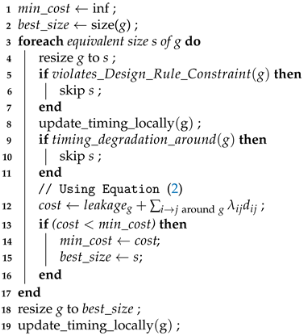
Algorithm 1: Find best size for gate g.
Technologies 09 00092 i001

3. Incremental LR-Based Gate Sizing

The overall effectiveness of an LM-based gate sizer is the combined result of the initialization of gate sizes, the strength of the local optimization, and the appropriate update of LMs.
Initializing all cells to their minimum size simplifies the removal of any design rule violations and also may alleviate the design from timing violations because some gates are faster due to the less output load. After initialization, the total leakage power in cost function (2) assumes its minimum value. Thus, the sum of λ i j d i j products determine which cell should be selected for each gate. This conclusion holds even if leakage and delay participate normalized to the cost function. Increasing fast the LMs of critical timing arcs guides the optimization to reduce their corresponding delay to minimize their λ i j d i j product. As long as timing constraints are not satisfied, LMs keep increasing thus leading to cells with improved delay.

3.1. What Is the Problem?

In an incremental optimization scenario, which is the focus of this work, the first step of the state-of-the-art LR-based gate sizing flow as depicted in Figure 3 cannot be applied. Since the design is almost finalized, the gate sizer is not allowed to “reset” the state of the design and initialize every gate to its minimum size. Therefore, since all gates keep their already decided size the sum of leakage power in (2) may possibly dominate the cost function. The LMs that fit to this occasion are unknown and initializing all of them to an a priori value, e.g., 1, may not be the best choice.
Inevitably, at the first iterations of LR-based gate sizing, lower power cells would be preferred for each gate since they would minimize local cost at the expense of timing. Once timing would starting getting much worse and the corresponding LMs start to take higher values, only then the λ i j d i j products would favor the selection of the delay-optimal cells. Due to improper initialization, state-of-the-art LR-based gate sizers exhibit a counterproductive behavior. The less timing critical is the initial state of the design, the more time an LR-based gate sizer would need to optimize it, when resetting the state of the design is not allowed.
To highlight this behavior, we performed an experiment using the pci_bridge32_fast design of the ISPD13 benchmark set. Figure 4 depicts the evolution of the design’s Total Negative Slack (TNS) during LR-based gate sizing for three different cases. When the design suffers from many timing violations (case A), the LR-based gate sizer is able to find fast the way to improve timing, leading to almost closed timing after the first six iterations. The remaining iterations are used to improve leakage power without degrading timing in the meantime.
On the other hand, if the design had initially less TNS (case B), LR-based gate sizer prefers to improve power by degrading timing in the first six iterations before it starts solving timing violations and achieving timing closure in iteration eleven. Similarly, if LR-based gate sizing is applied on an already optimized design with only few timing violations (case C), it will first convert many nontiming critical paths to critical before actually reducing TNS to almost zero.
Regardless of the initial TNS, LR-based gate sizing is powerful enough to solve all timing violations. However, due to improper initialization, it fails to do this fast in cases that it should have. Therefore, for the case of partially optimized designs with a small set of timing violations, like case C of Figure 4, we need to derive an incremental version of the LR-based gate sizer that would achieve high quality-of-results and fast convergence.

3.2. What Can We Do about It?

To improve the applicability of the LR-based discrete gate sizer in an incremental optimization context, we propose an efficient method for initializing the values of the LMs so that the value of each LM is adaptive to the initial design state. In this way, the LMs are not set to an a priori chosen value but the values of the LMs would reflect the proper timing criticality of each gate relative to its already selected size, as seen near the end of the physical synthesis flow. The proposed approach is nonintrusive, since it deals only with the initialization of the LMs, and can be used with any LR-based gate sizer [15,31,32].
Determining the initial values of the LMs should not be based solely on the criticality of the corresponding timing arcs. Assume, for instance, that the design contains a very large gate that contributes a lot to its leakage power and currently has zero timing violations. In fact, we may assume that its output pin has a small positive slack. If we assign to this gate a small initial LM due to its positive slack, we would lead the optimizer to downsize it in the first iterations to save power. This choice may seem reasonable but it fails to answer one critical question: why this gate has not been downsized earlier by the multiple optimization steps that preceded? The most probable answer is that this gate originally belonged to a set of critical timing paths. Optimizing those paths in the first steps of the flow, resulted in selecting for this gate a fast (with small delay) but large cell. Thus, any trial to reduce its size at the end of the flow would directly translate to new timing violations.
Based on this intuition, we choose to initialize the LMs following a balanced approach. We assign increased LMs to timing arcs that are either critical at the moment or belong to high-power cells assuming that those cells may were timing critical in the past. This approach may lead to a temporary power overhead to cells that are indeed not critical but remained large for the wrong reasons (e.g., a previously applied optimization skipped them to save runtime). However, the first iterations of LR-based gate sizer would identify this by gradually reducing their corresponding LMs thus turning them to good candidates for power reduction.
The initial value for the LM of timing arc i j is set to:
λ i j = a i + d i j a j P ( g ) min P ( g ) K arc i j of gate g
Gate g refers to the gate where the timing arc i j belongs. The starting value for each LM is the product of two ratios. The first ratio reveals the timing criticality of the arc i j . If the corresponding timing arc is responsible for the late arrival time at the output pin of gate j, the sum of a i and the delay d i , j will be equal to a j thus setting the ratio to 1. In any other case, a j will be greater than the numerator and thus the ratio will result to a value less than 1 signifying the non criticality of the arc. The second ratio describes how much more power the current version of the cell spends P ( g ) relative to the minimum possible leakage power that it can spend using any compatible library cell for gate g. Overall, when timing critical arcs are coupled with high power cells will get much greater LM values. The exponent K helps to make faster the assigned LMs’ values, and we empirically set it to K = 2 .
Similarly, for the LMs that correspond to the timing arcs i k , where k is a timing endpoint:
λ i k = a k r k g a t e s P ( g ) g a t e s min P ( g ) K timing endpoint k
If the signal arrives at the timing endpoint k earlier than its required time r k , i.e., a k < r k , signaling that there is no timing violation, the first ratio will result in a value less than one. On the contrary, in cases that late timing is violated, with a k > r k , the first ratio will be as big as the actual violation. For the power ratio in the case of timing endpoints, we suggest that it should consider the design as a whole. For this reason, the power ratio that is multiplied to the the timing ratio, divides the current total leakage power of the design relative to the minimum leakage power that the design can achieve after replacing each gate with a minimum leakage power cell. This ratio actually quantifies how far the design is from its virtually minimum leakage power.
Once the LMs were initialized, they need to be scaled to respect the KKT conditions as described in (3). Following (3) the sum of LMs of the output timing arcs of a gate should be equal to the timing arcs at its input. For instance, for the gate 6 shown in Figure 2, we should guarantee that λ 67 + λ 68 = λ 36 + λ 46 .
To achieve this, each one of the input LMs λ 36 and λ 46 receive a percentage of the sum of output LMs λ 67 + λ 68 . How much of the sum of output LMs would flow to each input LM is determined by the initial values λ 36 init and λ 46 init of timing arcs 3 6 and 4 6 , respectively.
λ 36 = λ 36 init λ 36 init + λ 46 init λ 67 + λ 68 λ 46 = λ 46 init λ 36 init + λ 46 init λ 67 + λ 68
The initial values of λ 36 init and λ 46 init are derived using Equation (5). When all gates were visited in reverse topological order and the LMs of the timing endpoints are propagated internally, the optimization can start.

4. Results

The proposed method was implemented in C++ inside the open-source RSyn physical design framework [44] after extending it for multicorner timing analysis. The evaluation involves already optimized benchmarks with only few timing violations. For this purpose, we used the fully optimized versions of the benchmarks of the ISPD 2013 gate sizing contest [37]. Those designs exhibit closed timing and minimized leakage power. To introduce additional timing violations, we randomly changed the resistance and capacitance of each net by ± 10 % , thus mimicking local rerouting operation at the end of the physical synthesis flow.
Our approach is experimentally validated using the benchmarks of the ISPD 2013 gate sizing contest considering a single and a multiple-corner scenario. For the case of multiple corners, we created two artificial (but realistic) timing libraries representing the fast (timing derate 1.05) and the slow version (timing derate 0.95) of the main typical library used in the single-corner case. Each cell in timing library has 10 sizes available at 3 Vth, with a total of 30 sizes per cell.

4.1. Quality-of-Results and Runtime Comparisons

Initially, we report the quality-of-results achieved for the proposed method (New) relative a state-of-the-art LR-gate sizer [31] (called Base) without allowing it to reset the state of the design. In other words, the optimization flow is the same as depicted in Figure 3 without performing the initial sizing step. Both cases actually utilize the same LR-based gate sizer. Their only difference is on how they initialize the value of the LMs. The obtained results are shown in Table 1 for single corner designs and in Table 2 for multicorner designs. Columns initially correspond to the design produced after randomly perturbing the resistance and capacitance of the wires. In all cases, the optimization stops if the improvement in terms of timing and leakage power across two iterations is less than 1 % . Table 1 and Table 2 report the late Worst Negative Slack (WNS), the late TNS and the total leakage power of each design under single and multiple corners, respectively. The final reported timing results are validated by OpenTimer [45]. ISPD2013 benchmarks do not exhibit early timing violations, and thus, early timing information is omitted.
The first noticeable result is that “New” offers better timing results than “Base” in the majority of the designs. With the proposed LM initialization, WNS is further decreased by 24 % on average, while TNS is improved by more than 36 % on average compared to the corresponding results of “Base” with only one corner. In multicorner designs, “New” helps improve WNS by a further 27 % on average, while TNS improves by more 39 % . In these cases, when timing slack reported is zero it means that timing constraints are satisfied in all corners. In all other cases, timing refers to the negative slack of the most critical corner.
“New” also achieves slightly better leakage power than “Base”. For fair comparison, we take into account only the leakage power savings from designs where both the “Base” and the “New” flow succeeded to resolve all timing violations. In those cases, in single corner designs “New” is 2% better on average, and 1 % better on average in multicorner designs. The reason for choosing only the timing closed designs is that whenever there are timing violations, the design’s power is lower than the power of the design with closed timing.
Figure 5 compares the two approaches in terms of runtime when the designs have one corner. All experiments were performed on the same Linux-based workstation using a 3.6 GHz Intel Core i7-4790 with four cores and 32 GB of RAM. “New” is able to save up to 45% of runtime on average achieving also better quality-of-results. In terms of absolute runtime, the single corner “Base” finishes optimizing all designs in 9 h, while the proposed flow needs 5 h for the same task. The runtime of “Base” and “New” methods for designs usb_phy (slow and fast) is similar due to their small size of the designs.
Similarly, Figure 6, reveals the runtime savings of the proposed approach in a multicorner timing scenario. The runtime of “New” is by 42 % on average less than the average runtime of “Base”. Multi-corner “Base” finishes optimizing all designs in 12 h. When the proposed initialization method is used, the total execution time is reduced to 6hrs. The overall increased execution time of multicorner optimization relative to the single corner scenario is due to the increased runtime of performing timing analysis on all corners.

4.2. Exploring in Depth the Proposed LM Initialization

Additional experimental results reveal that the way the LMs are initialized is crucial for the fast convergence and the overall timing QoR. Figure 7 compares the normalized late TNS of fft_fast design with one corner for different exponents K of the proposed Equations (5) and (6). As the value of exponent K increases, higher LMs are initialized to the timing critical arcs of the design. This means that the timing improves faster with better overall QoR. For all our experiments, we selected K = 2 because exponent values above K = 2 does not improve any further the QoR.
To observe more clearly how the proposed LM initialization helps the convergence of an LR-based gate sizer, we monitor the evolution of TNS across consecutive iterations initializing the LMs to different values. For the des_perf_fast design, shown in Figure 8, “Base” starts degrading the timing until iteration four where the TNS reaches 80 ns. From this point, the actual optimization starts and the timing closure is achieved in iteration ten. Applying the proposed Equations (5) and (6) (“New”), the optimizer starts reducing the timing violations immediately without degrading the initial state of the design and the timing constraints are met in iteration five. To further evaluate our work, we also tried to initialize the LMs to different values where the starting value of each LM was randomly selected (“Random”). In this case, the peak of the TNS is increased compared to the “Base” run. More specifically, the TNS in iteration four is increased from 80 ns to 110 ns, and thus, 3 more iterations were needed, compared to that of “Base”, to close the timing. Finally, we tested the performance of the LR-based gate sizer adopting the initialization method of work [31], in which the authors start all the LMs from 12. Even though this modification could slightly decrease the highest value of the TNS (compared to “Base”), the optimization showed slower convergence. The TNS improvement delayed to start and the timing constraints were finally met after multiple iterations, in iteration 15. From all the LM initialization trials, “New” showed the fastest convergence of all closing the timing really soon. Similar results are obtained for all other designs. The proposed LM initialization successfully “predicts” the value of the LM that fits better to the status of the design, thus avoiding unnecessary power reductions at the first iterations that would hurt timing initially and delay convergence later on.
To be certain for the quality-of-results of the proposed approach, we repeated the same experiment for each benchmark 100 times. Each time, the methods under comparison were applied on designs produced after perturbing randomly the wire parasitics of the already optimized version of each benchmark. The histogram of TNS for the initial design, and the ones produced after applying “Base” and “New” methods are depicted in Figure 9 for benchmark fft_fast, while similar results are obtained for all other benchmarks.
TNS histograms reveal that both approaches successfully decreased the original TNS. “Base” decreased the mean of initial TNS from 225 ps to 65 ps, while “New” managed to compress the TNS histogram to the left side of the diagram, with the majority of samples gathered close to 5 ps.

4.3. Optimization with a Restricted Number of Available Gate Sizes

For completeness, we evaluated both “Base” and “New” methods under comparison in a more restrictive scenario. In this case, gate sizing is only allowed to resize cells only to their next bigger or smaller size without limiting V T swapping options, since they do not alter the physical layout. This restriction makes sense at the final steps of physical design flow to preserve as much as possible the already defined detailed wire routes. The obtained results of single corner and multicorner benchmarks are depicted in Table 3 and in Table 4, respectively. Besides the restricted availability of gate sizes, “New” achieves considerable improvements. In single corner designs, late WNS is improved by 36 % on average while the savings in TNS reach 39 % on average, when compared to that of the baseline single corner LR-based gate sizer. In terms of leakage power, the restricted “New” method achieves less leakage power by 2 % on average, when considering only the designs without negative slack at both methods under comparison. For multiple corners, late WNS is improved by 35 % on average, while late TNS improves by 39 % on average when compared to the corresponding timing results of “Base”. Also “New” achieves slightly less leakage power by 2 % on average.

5. Conclusions

Efficient incremental and minimally disruptive optimization steps at the end of the design flow are crucial for the overall success of automated physical synthesis. In this work, instead of relying on custom-made timing and power optimization heuristics, we leverage, for the first time—to the best of our knowledge—LR-based optimizers used for the global optimization of the design as fast incremental optimizers after appropriate initialization. Initialization involves selecting appropriate values for the LMs after taking into account both their timing criticality, in a multicorner context, as well as the current size of the gates. In this way, we expedite successfully the convergence of the LR-based gate sizer, when applied in an incremental optimization context, without affecting any part of its internal functions and without reducing the achieved quality-of-results.
Experimental results also showed that relying on constant LM initialization values as done by similar state-of-the-art optimizers or using randomly selected constants do not achieve the smooth convergence needed in the case of last-mile incremental timing optimizations. Initializing the LMs with hand-selected constants provides an inaccurate picture of the design to the LR optimizer. This picture translates to unnecessary power reductions and timing degradation at the beginning of the optimization and inevitably leads to many more iterations before reconverging back to an timing optimized solution. This deficit was corrected by the proposed approach and allows LR-based global optimizers to be successfully used as fast incremental timing optimizers.
Our future plans are to incorporate the proposed LM initialization strategy into similar timing-driven placement engines that tradeoff placement density and wirelength for better timing performance.

Author Contributions

All authors have contributed equally and substantially to all parts of this manuscript. Conceptualization, D.M. and G.D.; methodology, D.M. and G.D.; writing—original draft preparation, D.M. and G.D. All authors have read and agreed to the published version of the manuscript.

Funding

Dimitrios Mangiras is supported by the Onassis Foundation—Scholarship ID: G ZO 014-1/2018-2019.

Institutional Review Board Statement

Not applicable.

Informed Consent Statement

Not applicable.

Data Availability Statement

Not applicable.

Conflicts of Interest

The authors declare no conflict of interest.

References

  1. Lavagno, L.; Martin, G.; Markov, I.L.; Scheffer, L.K. Electronic Design Automation for IC Implementation, Circuit Design, and Process Technology; Taylor and Francis Group: Boca Raton, FL, USA, 2016. [Google Scholar]
  2. Liu, Y.; Hu, J.; Shi, W. Multi-Scenario Buffer Insertion in Multi-Core Processor Designs. In Proceedings of the 2008 International Symposium on Physical Design, Portland, OR, USA, 13–16 April 2008; pp. 15–22. [Google Scholar]
  3. Roy, S.; Liu, D.; Um, J.; Pan, D.Z. OSFA: A new paradigm of gate-sizing for power/performance optimizations under multiple operating conditions. In Proceedings of the Design Automation Conference (DAC), San Francisco, CA, USA, 8–12 June 2015; pp. 1–6. [Google Scholar]
  4. MacDonald, N.D. Timing Closure in Deep Submicron Designs. In Proceedings of the Design Automation Conference (DAC), Anaheim, CA, USA, 13–18 July 2010. [Google Scholar]
  5. Chinnery, D.G.; Keutzer, K. Linear Programming for Sizing, Vth and Vdd Assignment. In Proceedings of the International Symposium on Low Power Electronics and Design (ISLPED), San Diego, CA, USA, 8–10 August 2005; pp. 149–154. [Google Scholar]
  6. Spindler, P.; Schlichtmann, U.; Johannes, F.M. Abacus: Fast legalization of standard cell circuits with minimal movement. In Proceedings of the International Symposium on Physical Design (ISPD), Portland, OR, USA, 13–16 April 2008; pp. 47–53. [Google Scholar]
  7. Puget, J.C.; Flach, G.; Reis, R.; Johann, M. Jezz: An effective legalization algorithm for minimum displacement. In Proceedings of the Symposium on Integrated Circuits and Systems Design (SBCCI), Salvador, Brazil, 31 August–4 September 2015; pp. 1–5. [Google Scholar]
  8. Chowdhary, A.; Rajagopal, K.; Venkatesan, S.; Cao, T.; Tiourin, V.; Parasuram, Y.; Halpin, B. How Accurately Can We Model Timing in a Placement Engine? In Proceedings of the ACM/IEEE Design Automation Conference (DAC), Anaheim, CA, USA, 13–17 June 2005; pp. 801–806. [Google Scholar]
  9. Alpert, C.; Chu, C.; Gandham, G.; Hrkić, M.; Hu, J.; Kashyap, C.; Quay, S. Simultaneous Driver Sizing and Buffer Insertion Using a Delay Penalty Estimation Technique. In Proceedings of the International Symposium on Physical Design (ISPD), San Diego, CA, USA, 7–10 April 2002; pp. 104–109. [Google Scholar]
  10. Stefanidis, A.; Mangiras, D.; Nicopoulos, C.; Chinnery, D.; Dimitrakopoulos, G. Autonomous Application of Netlist Transformations inside Lagrangian Relaxation-based Optimization. IEEE Trans. Comput.-Aided Des. Integr. Circuits Syst. 2021, 40, 1672–1686. [Google Scholar] [CrossRef]
  11. Jiang, Y.; Sapatnekar, S.S.; Bamji, C.; Kim, J. Interleaving buffer insertion and transistor sizing into a single optimization. IEEE Trans. VLSI Syst. 1998, 6, 625–633. [Google Scholar] [CrossRef] [Green Version]
  12. Fishburn, J.P. Clock Skew Optimization. IEEE Trans. Comput. 1990, 39, 945–951. [Google Scholar] [CrossRef] [Green Version]
  13. Kim, S.; Do, S.; Kang, S. Fast Predictive Useful Skew Methodology for Timing-Driven Placement Optimization. In Proceedings of the ACM/IEEE Design Automation Conference (DAC), Austin, TX, USA, 18–22 June 2017; pp. 55:1–55:6. [Google Scholar]
  14. Fishburn, J.P.; Dunlop, A.E. TILOS: A posynomial programming approach to transistor sizing. In ICCAD 2003; Springer: Boston, MA, USA, 2003. [Google Scholar]
  15. Ozdal, M.M.; Burns, S.; Hu, J. Algorithms for Gate Sizing and Device Parameter Selection for High-Performance Designs. IEEE Trans. CAD 2012, 31, 1558–1571. [Google Scholar] [CrossRef]
  16. Coudert, O. Gate Sizing for Constrained Delay/Power/Area Optimization. IEEE Trans. VLSI Syst. 1997, 5, 465–472. [Google Scholar] [CrossRef] [Green Version]
  17. Nguyen, D.; Davare, A.; Orshansky, M.; Chinnery, D.; Thompson, B.; Keutzer, K. Minimization of Dynamic and Static Power Through Joint Assignment of Threshold Voltages and Sizing Optimization. In Proceedings of the 2003 International Symposium on Low Power Electronics and Design (ISLPED ’03), Seoul, Korea, 25–27 August 2003; pp. 158–163. [Google Scholar]
  18. Bhattacharya, K.; Ranganathan, N. A Linear Programming Formulation for Security-Aware Gate Sizing. In Proceedings of the ACM Great Lakes Symposium on VLSI (GLSVLSI ’08), Orlando, FL, USA, 4–6 May 2008; pp. 273–278. [Google Scholar]
  19. Berkelaar, M.; Jess, J. Gate sizing in MOS digital circuits with linear programming. In Proceedings of the European Design Automation Conference, Glasgow, UK, 12–15 March 1990; pp. 217–221. [Google Scholar]
  20. Jeong, K.; Kahng, A.B.; Yao, H. Revisiting the linear programming framework for leakage power vs. performance optimization. In Proceedings of the 2009 10th International Symposium on Quality Electronic Design, San Jose, CA, USA, 16–18 March 2009; pp. 127–134. [Google Scholar]
  21. Reimann, T.; Posser, G.; Flach, G.; Johann, M.; Reis, R. Simultaneous gate sizing and Vt assignment using Fanin/Fanout ratio and Simulated Annealing. In Proceedings of the 2013 IEEE International Symposium on Circuits and Systems (ISCAS), Beijing, China, 19–23 May 2013; pp. 2549–2552. [Google Scholar]
  22. Daboul, S.; Hähnle, N.; Held, S.; Schorr, U. Provably Fast and Near-Optimum Gate Sizing. IEEE Trans. Comput.-Aided Des. Integr. Circuits Syst. 2018, 37, 3163–3176. [Google Scholar] [CrossRef]
  23. Hu, S.; Ketkar, M.; Hu, J. Gate Sizing For Cell Library-Based Designs. In Proceedings of the 2007 44th ACM/IEEE Design Automation Conference, San Diego, CA, USA, 4–8 June 2007; pp. 847–852. [Google Scholar]
  24. Ozdal, M.M.; Burns, S.; Hu, J. Gate sizing and device technology selection algorithms for high-performance industrial designs. In Proceedings of the 2011 IEEE/ACM International Conference on Computer-Aided Design (ICCAD), San Jose, CA, USA, 7–10 November 2011; pp. 724–731. [Google Scholar]
  25. Rahman, M.; Tennakoon, H.; Sechen, C. Library-Based Cell-Size Selection Using Extended Logical Effort. IEEE Trans. Comput.-Aided Des. Integr. Circuits Syst. 2013, 32, 1086–1099. [Google Scholar] [CrossRef]
  26. Liu, Y.; Hu, J. A New Algorithm for Simultaneous Gate Sizing and Threshold Voltage Assignment. IEEE Trans. Comput.-Aided Des. Integr. Circuits Syst. 2010, 29, 223–234. [Google Scholar] [CrossRef] [Green Version]
  27. Hu, J.; Kahng, A.B.; Kang, S.; Kim, M.C.; Markov, I.L. Sensitivity-guided metaheuristics for accurate discrete gate sizing. In Proceedings of the IEEE International Conference CAD, San Jose, CA, USA, 5–8 November 2012; pp. 233–239. [Google Scholar]
  28. Kahng, A.B.; Kang, S.; Lee, H.; Markov, I.L.; Thapar, P. High-performance Gate Sizing with a Signoff Timer. In Proceedings of the International Conference on Computer-Aided Design (ICCAD), San Jose, CA, USA, 18–21 November 2013; pp. 450–457. [Google Scholar]
  29. Fatemi, H.; Kahng, A.B.; Lee, H.; Li, J.; Pineda de Gyvez, J. Enhancing sensitivity-based power reduction for an industry IC design context. Integration 2019, 66, 96–111. [Google Scholar] [CrossRef]
  30. Lu, Y.C.; Nath, S.; Khandelwal, V.; Lim, S.K. RL-Sizer: VLSI Gate Sizing for Timing Optimization using Deep Reinforcement Learning. In Proceedings of the 2021 58th ACM/IEEE Design Automation Conference (DAC), San Francisco, CA, USA, 5–9 December 2021; pp. 733–738. [Google Scholar]
  31. Flach, G.; Reimann, T.; Posser, G.; Johann, M.; Reis, R. Effective Method for Simultaneous Gate Sizing and Vth Assignment Using Lagrangian Relaxation. IEEE Trans. Comput.-Aided Des. Integr. Circuits Syst. 2014, 33, 546–557. [Google Scholar] [CrossRef]
  32. Sharma, A.; Chinnery, D.; Bhardwaj, S.; Chu, C. Fast Lagrangian Relaxation Based Gate Sizing Using Multi-Threading. In Proceedings of the IEEE Inter. Conf. on Computer-Aided Design, Austin, TX, USA, 2–6 November 2015; pp. 426–433. [Google Scholar]
  33. Sharma, A.; Chinnery, D.; Dhamdhere, S.; Chu, C. Rapid gate sizing with fewer iterations of Lagrangian Relaxation. In Proceedings of the 2017 IEEE/ACM International Conference on Computer-Aided Design (ICCAD), Irvine, CA, USA, 13–16 November 2017; pp. 337–343. [Google Scholar]
  34. Livramento, V.S.; Guth, C.; Güntzel, J.L.; Johann, M.O. A Hybrid Technique for Discrete Gate Sizing Based on Lagrangian Relaxation. ACM Trans. Des. Autom. Electron. Syst. 2014, 19. [Google Scholar] [CrossRef]
  35. Shklover, G.; Emanuel, B. Simultaneous Clock and Data Gate Sizing Algorithm with Common Global Objective. In Proceedings of the 2012 ACM International Symposium on International Symposium on Physical Design, Napa, CA, USA, 25–28 March 2012; pp. 145–152. [Google Scholar]
  36. Li, L.; Kang, P.; Lu, Y.; Zhou, H. An efficient algorithm for library-based cell-type selection in high-performance. In Proceedings of the 2012 IEEE/ACM International Conference on Computer-Aided Design (ICCAD), San Jose, CA, USA, 5–8 November 2012; pp. 226–232. [Google Scholar]
  37. Ozdal, M.; Amin, C.; Ayupov, A.; Burns, S.M.; Wilke, G.R.; Zhuo, C. An Improved Benchmark Suite for the ISPD-2013 Discrete Cell Sizing Contest. In Proceedings of the International Symposium on Physical Design, Stateline, NV, USA, 24–27 March 2013; pp. 168–170. [Google Scholar]
  38. Mangiras, D.; Dimitrakopoulos, G. Incremental Lagrangian Relaxation based Discrete Gate Sizing and Threshold Voltage Assignment. In Proceedings of the 2021 10th International Conference on Modern Circuits and Systems Technologies (MOCAST), Thessaloniki, Greece, 5–7 July 2021; pp. 1–5. [Google Scholar]
  39. Bhasker, J.; Chadha, R. Static Timing Analysis for Nanometer Designs: A Practical Approach; Springer: Boston, MA, USA, 2009. [Google Scholar]
  40. Mangiras, D.; Stefanidis, A.; Seitanidis, I.; Nicopoulos, C.; Dimitrakopoulos, G. Timing-Driven Placement Optimization Facilitated by Timing-Compatibility Flip-Flop Clustering. IEEE Trans. Comput.-Aided Des. Integr. Circuits Syst. 2020, 39, 2835–2848. [Google Scholar] [CrossRef]
  41. Berkelaar, M.; Buurman, P.; Jess, J. Computing the entire active area/power consumption versus delay tradeoff curve for gate sizing with a piecewise linear simulator. IEEE Trans. Comput.-Aided Des. Integr. Circuits Syst. 1996, 15, 1424–1434. [Google Scholar] [CrossRef]
  42. Montiel-Nelson, J.; Sosa, J.; Navarro, H.; Sarmiento, R.; Núñez, A. Efficient method to obtain the entire active area against circuit delay time trade-off curve in gate sizing. IEE Proc.-Circuits Dev. Syst. 2005, 152, 133–145. [Google Scholar] [CrossRef]
  43. Tennakoon, H.; Sechen, C. Nonconvex Gate Delay Modeling and Delay Optimization. IEEE Trans. Comput.-Aided Des. Integr. Circuits Syst. 2008, 27, 1583–1594. [Google Scholar] [CrossRef]
  44. Flach, G.; Fogaça, M.; Monteiro, J.; Johann, M.; Reis, R. Rsyn: An Extensible Physical Synthesis Framework. In Proceedings of the International Symposium on Physical Design, Portland, OR, USA, 19–22 March 2017; pp. 33–40. [Google Scholar]
  45. Huang, T.W.; Wong, M.D.F. OpenTimer: A high-performance timing analysis tool. In Proceedings of the IEEE/ACM International Conference on Computer-Aided Design (ICCAD), Austin, TX, USA, 2–6 November 2015; pp. 895–902. [Google Scholar]
Figure 1. Definition of arrival times a i , a j and delay d i , j for (a) combinational gates, (b) primary outputs and (c) flip-flops.
Technologies 09 00092 g001
Figure 2. Example design to show which LMs are considered in computation of local cost and to present LM equalities to preserve optimality KKT conditions, which imply that sum of input LMs must be equal to sum of output LMs. Thus, for highlighted gate 6, LMs λ 13 , λ 23 , λ 24 , λ 35 , λ 36 , λ 46 , λ 67 and λ 68 multiplied with their corresponding delays will form local cost. For LM propagation, for gate 6, we should guarantee that λ 36 + λ 46 = λ 67 + λ 68 .
Technologies 09 00092 g002
Figure 3. Overall LR-based gate sizing optimization flow.
Technologies 09 00092 g003
Figure 4. Evolution of TNS on each iteration of a LR-based gate sizer for three cases of the same design. In case A, design is not optimized. In cases B and C, it is partially optimized, thus exhibiting initially less TNS.
Technologies 09 00092 g004
Figure 5. Runtime of both methods under comparison for all benchmarks when considering only one corner. Runtime is normalized to runtime of “Base” run. In all cases, “New” allows faster convergence saving up to 45 % execution time on average in single corner benchmarks.
Technologies 09 00092 g005
Figure 6. Runtime of both methods under comparison for all benchmarks when considering multiple corners. Runtime is normalized to runtime of “Base” run. In all cases, “New” allows faster convergence saving up to 42% on average with multiple corners.
Technologies 09 00092 g006
Figure 7. TNS comparison for different values of exponent K for LM initialization as proposed in Equations (5) and (6) for representative design, fft_fast. Higher values of K increase LMs of critical arcs leading to faster TNS improvement during optimization iterations. Beyond K = 2 , there are not sufficient savings.
Technologies 09 00092 g007
Figure 8. Progression of late TNS on des_perf_fast design using different LM initialization methods; initializing LMs to 1 (Base), using proposed method (New), initializing each LM to a random value (Random) and using initialization of [31] (Ref [31]).
Technologies 09 00092 g008
Figure 9. Histogram of late TNS initially (Init) and at end of LR-based gate sizing without (Base) and with (New) proposed LM initialization. Histograms correspond to 100 versions of fft_fast with randomly perturbed RC characteristics.
Technologies 09 00092 g009
Table 1. Timing and leakage power of all designs under single corner initially (Init) and at end of incremental LR-based sizer without (Base) and with (New) proposed LM initialization.
Design#CellsSingle Corner
Late WNS (ps)Late TNS (ps)Leakage (mW)
InitBaseNewInitBaseNewInitBaseNew
usb_phy_slow623−1.530.000.00−1.530.000.00111
usb_phy_fast−0.610.000.00−0.610.000.00222
pci_bridge32_slow30,763−11.210.000.00−333.100.000.00585858
pci_bridge32_fast−16.66−0.440.00−614.66−0.960.009897100
fft_slow33,792−16.350.000.00−320.920.000.00888887
fft_fast−18.18−6.58−1.88−234.28−63.37−4.25217228228
cordic_slow42,937−13.99−14.43−1.24−801.84−116.70−2.11306349309
cordic_fast−13.26−4.26−6.94−752.72−30.00−31.4011391142933
des_perf_slow113,346−30.40−1.880.00−11,920.00−5.260.00449410420
des_perf_fast−25.80−3.51−4.10−11,412.20−49.94−8.69609522556
edit_dist_slow129,227−54.440.000.00−21,881.500.000.00452447445
edit_dist_fast−63.59−3.340.00−36,639.50−15.160.00624630610
matrix_mult_slow159,642−44.000.000.00−3292.930.000.00481487476
matrix_mult_fast−33.070.000.00−2694.750.000.00105612301020
netcard_slow984,094−30.190.000.00−1477.580.000.00516051015102
netcard_fast−28.970.000.00−6394.270.000.00520351445141
Average−25.14−2.15−0.89−6173.27−17.59−2.90996996968
Table 2. Timing and leakage power of all designs under multiple corners initially nd at end of incremental LR−based sizer without (Base) and with (New) proposed LM initialization.
DesignMultiple Corners
Late WNS (ps)Late TNS (ps)Leakage (mW)
InitBaseNewInitBaseNewInitBaseNew
usb_phy_slow−0.030.000.00−0.030.000.00111
usb_phy_fast−6.38−4.990.00−14.39−8.570.00323
pci_bridge32_slow−14.760.000.00−485.440.000.00605959
pci_bridge32_fast−21.40−4.250.00−280.77−14.780.00194151153
fft_slow−10.74−0.140.00−194.37−0.270.00969798
fft_fast−8.210.000.00−449.160.000.00356426391
cordic_slow−24.57−0.68−2.06−1000.51−1.09−2.06518561527
cordic_fast−122.26−92.07−66.50−5412.47−2954.33−1710.28260431893220
des_perf_slow−34.07−29.24−14.08−11,391.80−42.13−26.27723704715
des_perf_fast−77.49−46.25−33.07−19,884.50−737.60−216.1512729261038
edit_dist_slow−67.660.000.00−36,892.700.000.00477473471
edit_dist_fast−68.96−11.220.00−39,745.10−77.410.00766791754
matrix_mult_slow−43.790.000.00−3254.510.000.00576591574
matrix_mult_fast−36.16−45.23−33.02−3243.41−107.50−41.07187623572302
netcard_slow−42.250.000.00−2251.090.000.00516351055105
netcard_fast−28.96−1.230.00−10,606.80−2.340.00524551875183
Average−37.98−14.71−9.3−8444.19−246.63−124.74124612891287
Table 3. Timing and leakage power of all designs under single corner with gate size selection restriction without (Base) and with (New) proposed LM initialization.
DesignSingle Corner
Late WNS (ps)Late TNS (ps)Leakage (mW)
BaseNewBaseNewBaseNew
usb_phy_slow0.000.000.000.0011
usb_phy_fast0.000.000.000.0022
pci_bridge32_slow0.000.000.000.005858
pci_bridge32_fast−1.650.00−6.130.009898
fft_slow0.000.000.000.008887
fft_fast−6.87−1.01−20.18−2.24224221
cordic_slow−8.79−2.96−67.21−2.96378310
cordic_fast−17.06−2.73−133.10−4.811209942
des_perf_slow−27.50−1.40−67.53−4.52480464
des_perf_fast−14.41−7.61−47.42−23.30637611
edit_dist_slow0.000.000.000.00450449
edit_dist_fast−20.77−1.95−698.80−2.16623619
matrix_mult_slow0.000.000.000.00478479
matrix_mult_fast0.000.000.000.0011741020
netcard_slow0.000.000.000.0051525153
netcard_fast0.000.000.000.0051975194
Average−6.07−1.10−65.02−2.501016982
Table 4. Timing and leakage power of all designs under multiple corners with gate size selection restriction without (Base) and with (New) proposed LM initialization.
DesignMultiple Corners
Late WNS (ps)Late TNS (ps)Leakage (mW)
BaseNewBaseNewBaseNew
usb_phy_slow0.000.000.000.0011
usb_phy_fast−12.810.00−42.000.0022
pci_bridge32_slow0.000.000.000.006260
pci_bridge32_fast−22.20−21.24−189.58−154.97170170
fft_slow0.000.000.000.0010098
fft_fast−22.480.00−92.880.00366365
cordic_slow−1.480.00−1.860.00705516
cordic_fast−113.97−112.70−5604.24−4867.8033253389
des_perf_slow−30.88−18.45−207.30−125.34728713
des_perf_fast−68.24−47.37−1520.11−386.8112051229
edit_dist_slow0.000.000.000.00478477
edit_dist_fast−3.11−0.48−3.11−0.85824758
matrix_mult_slow0.000.000.000.00602580
matrix_mult_fast−26.23−27.31−42.98−43.5422142154
netcard_slow0.000.000.000.0051725158
netcard_fast−4.700.00−7.600.0052505236
Average−19.13−14.22−481.98−348.7113251307
Publisher’s Note: MDPI stays neutral with regard to jurisdictional claims in published maps and institutional affiliations.

