Abstract
Consideration of heat treatment in simulations of structural components and its impact on predictions of behaviour during operation is analysed here. An automotive machine element with a complex geometry and dynamic load is analysed rather than a standard laboratory specimen under controlled conditions. The heat treatment analysis of a starter clutch barrel has been performed in DANTE followed by a structural analysis in ANSYS 2019 R3 during operation simulating a load cycle due to the start of an internal combustion engine. The heat treatment simulation consisted of carburisation, quenching and tempering. First, the carbon content and its distribution have been simulated. Next, the hardness of the starter clutch barrel and its distribution have been analysed with respect to the carbon distribution and hardness-dependent material properties of the AISI/SAE 4142 steel. Finally, the stress field after the heat treatment and during the operation of the starter clutch barrel has been thoroughly evaluated and compared to the simulation without the consideration of the heat treatment. Results of the simulation show that the heat treatment introduces favourable compressive stresses at the critical location of the starter clutch barrel and reduces the effective amplitude of the equivalent stress during the operation. Furthermore, the results of the simulation prove that heat treatment should be considered already during the early stages of the R & D process as it can have a decisive effect on the operational behaviour of the structural component. Moreover, a non-consideration of the heat treatment can lead into erroneous conclusions regarding the suitability of machine elements.
1. Introduction
Evaluations of machine elements include structural and durability analyses already in the early stages of development [1,2,3,4]. These analyses must contain realistic thermomechanical loads which originate from the use of mechanical components and the environment in which they operate [2,5,6,7]. Considering representative mechanical properties and suitable material models, credible predictions of components during operation can be obtained for either confirmation of the project requirements or further design changes of the components [1,2,8,9,10].
Back-stresses in material as a consequence of the manufacturing procedure can considerably influence the stress-strain behaviour during the typical use of components [9,11,12,13,14]. Quenching of a long annular rod causes a complex distribution of the tangential and the radial stresses along the radius including both tensile and compressive back-stresses, as shown by Bammann et al. [11]. Equivalently, the temperature, microstructure and stress evolutions of a shaft part of SAE 4140H steel were simulated for different induction heat treatment processes by Tong et al. [15]. In the study of Song et al. [16], the carbon content distribution during the carburising process of the gear ring was followed by performing a finite element analysis and then based on the results, the quenching process was simulated; the distributions of the microstructure, temperature and stress fields versus time and space were analysed. Another study by Guo et al. [17] simulated the low-pressure vacuum carburising process of a round sample by the heat treatment software COSMAP and compared it against the experimental results to find a good agreement between the simulated surface carbon concentration and experimental values. Similarly, Ferguson et al. [18] simulated the heat treatment using finite element based tool DANTE to compare two quench hardening processes to improve the tooth bending fatigue strength of carburised steel gears used in helicopter transmissions. A simulation of a steel gear heat treatment was also presented in a study by Greif et al. [12] where authors performed the analysis using simulation tools AVL FIRE and DANTE. Recently, Tian et al. [13] validated a new finite element model to precisely simulate the temperature distribution of a bainite/martensite multiphase material during water-air alternating surface quenching process and compared it to the results of a quarter of axle block experiments. SongSong et al. [19] simulated electromagnetic induction quenching of a crankshaft which enabled an accurate determination of the stress field later used for fatigue properties. Quenching process of a steel gear in water and oil medium was investigated by Esfahani et al. [14] in a study of the quenching behaviour of low alloy steels coupled with the temperature dependence of ferrite formation and stress dependence of martensitic transformation. Lombardi et al. [20] used in-situ and ex-situ neutron diffraction to measure the change in residual strain in the cylinder bridge of an aluminium alloy engine block as a function of time during the solution heat treatment and created stress profiles following the heat treatment. A recent development of simulations has been reported by Fomin et al. [21] who observed good correspondence between the results of numerical simulations and experimental data for induction heat treatment of titanium disks.
Although a broad amount of studies regarding the heat treatment of machine elements is available, a study focusing on a starter clutch barrel has not been reported to date. The complex geometry of the starter clutch barrel creates an intricate simulation challenge as only an accurate determination of the stress field in the product can aid the decision regarding its operational suitability. This paper thus aims attention at the simulation of the heat treatment of a starter clutch barrel. Furthermore, the investigation examines how the heat treatment during the manufacturing phase of the machine element influences its behaviour later on during the operation period. Namely, the mechanical behaviour of a starter clutch barrel is studied by consideration of both the manufacturing process and the typical operational load. The main focus of the study is the analysis of a real industrial problem where both the geometry of the product—starter clutch barrel and the technology—heat treatment have been pre-defined and decision on the suitability of the machine element has to be made before the manufacturing of the prototype. The simulated stress field in the starter clutch barrel serves here as the decisive evidentiary information of whether a successful operation is expected.
The starter clutch is a one way roller clutch and a key component in a starter motor that is used to crank internal combustion engines [22]. At start-up, the torque is transmitted from an electric motor via the starter clutch barrel (also named the “body” of the clutch) to a ring gear mounted on a cranking shaft. As high shear stresses on the barrel due to the torque application during operation may result in the cracked barrel failure, heat treatment is a part of the typical process in the starter clutch barrel production to prevent the failure, during which the carburising, quenching and tempering processes are included.
2. Method
The mathematical expression for the carburisation process can be formulated as [16]
where C and D are weight percentage of carbon and diffusion coefficient of carbon at the location described by coordinates x, y and z at time t, respectively. Similarly, the temperature field during the heat treatment can be described by [16]
where , c, k, T and Q stand for material density, specific heat, heat conduction coefficient, temperature and potential heat of phase transformation at the location described by coordinates x, y and z at time t, respectively. Additionally, thermal boundary conditions play an important role consisting of ambient temperature and heat transfer coefficient between the outer surface of the machine element and the surrounding medium. The structural response of the material during the heat treatment is based on the incremental theory considering elastoplastic material properties and decomposition of total strain increment into [16,23]
where , , and represent elastic, plastic, thermal and phase transformation increments, respectively. Moreover, phase transformations in the solid state and temperature-dependent properties of material phases have a great impact on the simulation results. Equations (1)–(3) with corresponding boundary conditions stand for the basis of the stress field calculation considering both the manufacturing process and the typical operational load. But even quenching of a simple element, such as a long annular rod, causes a complex distribution of the tangential and the radial stresses along the radius [11]. The stress field in complex structural components, though still determined by Equations (1)–(3), is thus solved numerically. Due to the complex geometry of the starter clutch barrel, the heat treatment simulation has been carried out using the finite element analysis in DANTE, implemented into ANSYS 2019 R3. The geometry of the clutch barrel was first simplified for the analysis and meshed with around 73,000 nodes and 203,000 solid finite elements (Figure 1). The finite element mesh consisted of six layers of wedge elements under the surface and tetrahedral elements in the core. A higher mesh density was used towards the outer surface of the starter clutch barrel as this is mandatory to simulate the high surface gradients of carbon content, temperature and resulting stress-strain field during the heat treatment process. Moreover, as the geometry of the contact points between the starter clutch barrel and the rollers is not symmetric, a full 3D model has been considered during the simulation. The heat treatment simulation consisted of three steps, including carburisation, quenching and tempering. The timeline of the heat treatment is depicted in Figure 2.
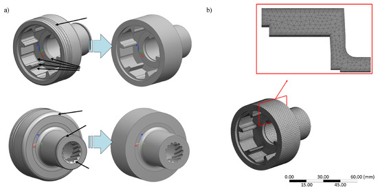
Figure 1.
(a) Geometry of the starter clutch barrel and its simplification—arrows show the simplified details. (b) Finite element mesh—mesh density increases towards the outer surface in order to simulate high surface gradients during the heat treatment process.
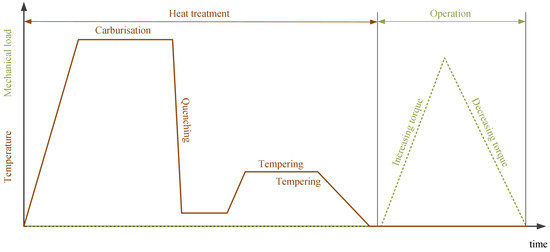
Figure 2.
The timeline of the heat treatment process and the typical operation.
After the simulation of the heat treatment process, the mechanical load was first applied to the starter clutch barrel, representing a typical operational condition during use, and afterwards withdrawn to complete the operational load cycle (Figure 2). For the comparison purposes, the same geometry of the starter clutch barrel was subjected to the same operational mechanical load but in this case, an initial zero-back-stress field was assumed. The two results hence only differed in the (non)consideration of the heat treatment of the starter clutch barrel.
Hardness-dependent material properties of the AISI/SAE 4142 steel, which is used for the starter clutch barrel (material properties during the simulation in DANTE correspond to the class 41XX), are given in Figure 3a. The heat transfer between the outer surface of the starter clutch barrel and the surrounding medium during the quenching part of the process was conditioned by the temperature-dependent heat transfer coefficient as given in Figure 4. During the simulation of the heat treatment process, the boundary conditions resembled the placement of the starter clutch barrel in the temperature chamber, e.g., the bottom surface was supported in the axial direction (flag B in Figure 3b). Additional supports of two points on this surface, one only in x-direction and the other in both x and z-directions (flags C and D in Figure 3b), prevented the rotation of the starter clutch barrel during the heat treatment process whilst enabling the expansion in the radial direction. The boundary conditions during the simulation of the operational cycle included an axial support on surface E in Figure 3b which resembled the contact between the starter clutch barrel and the pinion during the start-up of the internal combustion engine. Additionally, the contact points between the starter clutch barrel and the rollers were fixed in tangential and radial directions (flag F in Figure 3b) to simulate the resistance of the engine during the start-up. Finally, the starting torque was applied to the starter clutch barrel over the inner gearing (flag A in Figure 3b).
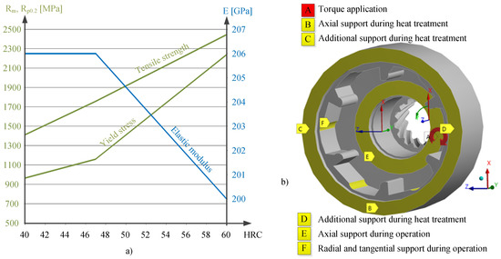
Figure 3.
(a) Hardness-dependent material properties of AISI/SAE 4142 steel [24]. (b) The boundary conditions during the heat treatment process and the typical operation.
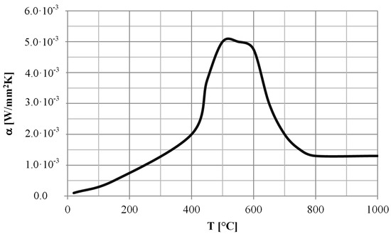
Figure 4.
Temperature-dependent heat transfer coefficient between the outer surface of the starter clutch barrel and the surrounding medium considered during the simulation.
3. Results and Discussion
The influence of the initial manufacturing stage, i.e., the forging of the starter clutch barrel, has not been considered in the simulation due to the high temperatures during the carburisation step of the heat treatment process which annihilates the back-stresses in the material.
The analysis of the carbon content in the starter clutch barrel (Figure 5a) shows that 0.75% of carbon is ensured on the outer surface which then gradually reduces to 0.2% of carbon in the middle of the cross-section of the clutch barrel. However, the highest carbon content of around 0.9% occurs at the exposed parts of the inner gearing. Similarly, the highest hardness of 61 HRC occurs on the outer surface of the starter clutch barrel and then decreases to 46 HRC towards the middle of the cross-section (Figure 5b).
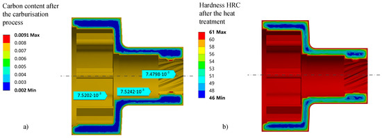
Figure 5.
(a) Carbon content distribution over the cross-section of the starter clutch barrel after the carburisation. (b) Hardness distribution over the cross-section of the starter clutch barrel after the heat treatment.
Radial, tangential and axial stresses after the heat treatment, at the time of operation and comparison with the non-heat-treated material are compared in Figure 6, Figure 7 and Figure 8, respectively.

Figure 6.
Radial stresses in the starter clutch barrel (a) after the heat treatment, (b) at the time of operation and (c) without the consideration of heat treatment at the time of operation.

Figure 7.
Tangential stresses in the starter clutch barrel (a) after the heat treatment, (b) at the time of operation and (c) without the consideration of heat treatment at the time of operation.

Figure 8.
Axial stresses in the starter clutch barrel (a) after the heat treatment, (b) at the time of operation and (c) without the consideration of heat treatment at the time of operation.
Due to the heat treatment, high tensile stresses in radial, tangential and axial directions occur in the middle of the cross-section of the starter clutch barrel (Figure 6a, Figure 7a and Figure 8a). Highest radial stresses reach about 300 MPa in the wall between the small and the big radius (Figure 6a). Tangential stresses also exceed 300 MPa throughout the middle of the cross-section with peak values of around 400 MPa in every corner of the cross-section (Figure 7a). Axial stresses exceeding 200 MPa remain after the heat treatment in the both longitudinal walls of the clutch barrel with peak values of more than 300 MPa in the wall of the big radius (Figure 8a). On the contrary, high compressive radial and tangential stresses can be observed on the surface of the starter clutch barrel. Whilst the highest compressive stresses occur on the surface of the vertical wall between the small and the big radius exceeding −450 MPa (Figure 6a), the highest compressive tangential stresses reach −400 MPa over the total outer surface (Figure 7a). Compressive axial stresses remain after the heat treatment on the surfaces of the longitudinal walls of the clutch barrel, but tensile axial stresses of about 100 MPa can be observed on the surface of the vertical wall (Figure 8a).
After application of the mechanical load, the values of the radial and tangential stresses do not alter considerably, whilst the axial stresses moderately change due to the axial support E shown in Figure 3b. As the starting torque was applied in the circumferential direction of the inner gearing, the axial stresses reached lower values in the simulation than they would have if the starting torque was applied over a contact between the inner gearing and its counterpart. Additionally, due to the discrete calculation and fine mesh at the surface, high peak values of the stresses can occur which are indicated by the arrows in Figure 7b. The radial, tangential and axial stresses remain at low values in the case of the non-heat-treated material (Figure 6c, Figure 7c and Figure 8c). Higher values not exceeding absolute values of 60 MPa occurred only at the inner gearing and at the contact points between the starter clutch barrel and the rollers.
Comparison of the shear stresses in the tangential-axial direction reveals the influence of the starter torque. It can be noticed from Figure 9 that the shear stresses reach around 25 MPa on the surface of the small radius at the time of operation (Figure 9b), whilst almost no shear stresses are present after the end of the heat treatment (Figure 9a). Similar values occur also in the case of the non-heat-treated material (Figure 9c).

Figure 9.
Shear stresses in the tangential-axial direction (a) after the heat treatment, (b) at the time of operation and (c) without the consideration of heat treatment at the time of operation.
Finally, if the course of the stress tensor in Figure 10 is compared for the material with and without heat treatment at the critical location (marked with red circle in Figure 9), it can be noticed that the heat treatment introduces a highly compressed area at the usual crack initiation side which favourably influences the fatigue lifetime of the starter clutch barrel. Although the shear stresses due to the mechanical load during the operation are the same for the heat-treated and non-heat-treated materials, the compressive axial, tangential and radial stresses shift the equivalent stress (here calculated by the von Mises criterion) downwards to the compressive area which hinders the initiation of a fatigue crack (Figure 10a). Moreover, high absolute values of the axial, tangential and radial stresses also decrease the effective amplitude of the equivalent stress which can be seen if compared in Figure 10a,b.
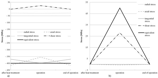
Figure 10.
Stress tensor components and equivalent stress at the critical location of the starter clutch barrel for material (a) with heat treatment and (b) without heat treatment. Compressive axial, tangential and radial stresses introduced by the heat treatment have a favourable effect on the course of the equivalent stress.
4. Conclusions
The evaluation of the heat treatment consideration in the case of the starter clutch barrel has revealed that considerable differences appear between the results of the simulation where the heat treatment of the material has been considered with those of the non-heat-treated material. Tensile axial, tangential and radial stresses occur inside of the wall after the heat treatment, whereas advantageous compressive stresses develop on the surface of the starter clutch barrel. Instead of the tensile equivalent stress with a considerable amplitude during the operation, compressive equivalent stress with a reduced amplitude is observed when the results of the heat treatment simulation are considered.
Author Contributions
Conceptualisation, D.Š. and M.K.; methodology, D.Š. and M.K.; software, M.K.; validation, D.Š. and M.K.; formal analysis, D.Š. and M.K.; investigation, D.Š. and M.K.; resources, J.K. and M.N.; data curation, D.Š. and M.K.; writing—original draft preparation, D.Š.; writing—review and editing, D.Š., M.K., J.K. and M.N.; visualisation, D.Š. and M.K.; supervision, J.K. and M.N.; project administration, D.Š.; funding acquisition, J.K. and M.N. All authors have read and agreed to the published version of the manuscript.
Funding
The authors acknowledge financial support from Javna Agencija za Raziskovalno Dejavnost RS: Research core funding No. P2-0182 entitled Development. Support from MAHLE Electric Drives Slovenia and DANTE Solutions, Inc. is greatly appreciated.
Conflicts of Interest
The authors declare no conflict of interest. The funders had no role in the design of the study; in the collection, analyses, or interpretation of data; in the writing of the manuscript, or in the decision to publish the results.
References
- Bartošák, M.; Horváth, J.; Pitrmuc, Z.; Rohlová, M. Life assessment of a low-alloy martensitic steel under isothermal low-cycle fatigue-creep and thermo-mechanical fatigue-creep loading conditions. Int. J. Fatigue 2021, 145, 106092. [Google Scholar] [CrossRef]
- Šeruga, D.; Hansenne, E.; Haesen, V.; Nagode, M. Durability prediction of EN 1.4512 exhaust mufflers under thermomechanical loading. Int. J. Mech. Sci. 2014, 84, 199–207. [Google Scholar] [CrossRef]
- Ubertalli, G.; Matteis, P.; Ferraris, S.; Marcianò, C.; D’Aiuto, F.; Tedesco, M.M.; De Caro, D. High Strain Rate Behavior of Aluminum Alloy for Sheet Metal Forming Processes. Metals 2020, 10, 242. [Google Scholar] [CrossRef] [Green Version]
- Nagode, M.; Šeruga, D.; Hack, M.; Hansenne, E. Damage Operator-Based Lifetime Calculation Under Thermomechanical Fatigue and Creep for Application on Uginox F12T EN 1.4512 Exhaust Downpipes. Strain 2011, 48, 198–207. [Google Scholar] [CrossRef]
- Xu, C.; Yu, M.; Wu, H. Simulation Analysis of Quenching Process of High Strength Steel Based on ABAQUS. IOP Conf. Ser. Mater. Sci. Eng. 2018, 423, 012075. [Google Scholar] [CrossRef]
- Kopec, M.; Kukla, D.; Brodecki, A.; Kowalewski, Z. Effect of high temperature exposure on the fatigue damage development of X10CrMoVNb9-1 steel for power plant pipes. Int. J. Press. Vessel. Pip. 2021, 189, 104282. [Google Scholar] [CrossRef]
- Gong, X.; Wang, T.; Li, Q.; Liu, Y.; Zhang, H.; Zhang, W.; Wang, Q.; Wang, Q. Cyclic responses and microstructure sensitivity of Cr-based turbine steel under different strain ratios in low cycle fatigue regime. Mater. Des. 2021, 201, 109529. [Google Scholar] [CrossRef]
- Nagode, M.; Laengler, F.; Hack, M. Damage operator based lifetime calculation under thermo-mechanical fatigue for application on Ni-resist D-5S turbine housing of turbocharger. Eng. Fail. Anal. 2011, 18, 1565–1575. [Google Scholar] [CrossRef]
- Pérez Caro, L.; Odenberger, E.L.; Schill, M.; Niklasson, F.; Åkerfeldt, P.; Oldenburg, M. Springback prediction and validation in hot forming of a double-curved component in alloy 718. Int. J. Mater. Form. 2021. [Google Scholar] [CrossRef]
- Klemenc, J.; Šeruga, D.; Nagode, A.; Nagode, M. Comprehensive Modelling of the Hysteresis Loops and Strain-Energy Density for Low-Cycle Fatigue-Life Predictions of the AZ31 Magnesium Alloy. Materials 2019, 12, 3692. [Google Scholar] [CrossRef] [PubMed] [Green Version]
- Bammann, D.; Prantil, V.; Kumar, A. Development of a carburizing and quenching simulation tool: A material model for low carbon steels undergoing phase transformations. In Proceedings of the International Conference on Quenching and the Control of Distortion, Cleveland, OH, USA, 4–7 November 1996. [Google Scholar]
- Greif, D.; Kopun, R.; Kosir, N.; Zhang, D. Numerical Simulation Approach for Immersion Quenching of Aluminum and Steel Components. Int. J. Automot. Eng. 2017, 8, 45–49. [Google Scholar] [CrossRef] [Green Version]
- Tian, Y.; Tan, Z.; Li, H.; Gao, B.; Zhu, J.; Liu, Y.; Zhang, M. A new finite element model for Mn-Si-Cr bainitic/martensitic product quenching process: Simulation and experimental validation. J. Mater. Process. Technol. 2021, 294, 117137. [Google Scholar] [CrossRef]
- Esfahani, A.K.; Babaei, M.; Sarrami-Foroushani, S. A numerical model coupling phase transformation to predict microstructure evolution and residual stress during quenching of 1045 steel. Math. Comput. Simul. 2021, 179, 1–22. [Google Scholar] [CrossRef]
- Tong, D.; Gu, J.; Yang, F. Numerical simulation on induction heat treatment process of a shaft part: Involving induction hardening and tempering. J. Mater. Process. Technol. 2018, 262, 277–289. [Google Scholar] [CrossRef]
- Song, G.S.; Liu, X.H.; Wang, G.D.; Xu, X.Q. Numerical Simulation on Carburizing and Quenching of Gear Ring. J. Iron Steel Res. Int. 2007, 14, 47–52. [Google Scholar] [CrossRef]
- Guo, J.; Deng, X.; Wang, H.; Zhou, L.; Xu, Y.; Ju, D. Modeling and Simulation of Vacuum Low Pressure Carburizing Process in Gear Steel. Coatings 2021, 11, 1003. [Google Scholar] [CrossRef]
- Ferguson, B.L.; Li, Z.; Freborg, A.M. Heat Treat Simulation Used to Improve Gear Performance. In Heat Treating Progress; ASM International: Almere, The Netherlands, 2007; Volume 7. [Google Scholar]
- SongSong, S.; Xingzhe, Z.; Chang, W.; Maosong, W.; Fengkui, Z. Crankshaft high cycle bending fatigue research based on the simulation of electromagnetic induction quenching and the mean stress effect. Eng. Fail. Anal. 2021, 122, 105214. [Google Scholar] [CrossRef]
- Lombardi, A.; Sediako, D.; Machin, A.; Ravindran, C.; MacKay, R. Effect of solution heat treatment on residual stress in Al alloy engine blocks using neutron diffraction. Mater. Sci. Eng. A 2017, 697, 238–247. [Google Scholar] [CrossRef]
- Fomin, A.; Koshuro, V.; Shchelkunov, A.; Aman, A.; Fomina, M.; Kalganova, S. Simulation and experimental study of induction heat treatment of titanium disks. Int. J. Heat Mass Transf. 2021, 165, 120668. [Google Scholar] [CrossRef]
- Xue, W.; Pyle, R. Optimal Design of Roller One Way Clutch for Starter Drives; SAE Technical Paper; SAE International: Warrendale, PA, USA, 2004. [Google Scholar]
- Alberg, H. Material Modelling for Simulation of Heat Treatment. Ph.D. Thesis, Lulea University of Technology, Lulea, Sweden, 2003. [Google Scholar]
- ASM International Handbook Committee. ASM Handbook, Volume 1: Properties and Selection: Irons, Steels, and High-Performance Alloys; ASM International: Almere, The Netherlands, 1990. [Google Scholar]
Publisher’s Note: MDPI stays neutral with regard to jurisdictional claims in published maps and institutional affiliations. |
© 2021 by the authors. Licensee MDPI, Basel, Switzerland. This article is an open access article distributed under the terms and conditions of the Creative Commons Attribution (CC BY) license (https://creativecommons.org/licenses/by/4.0/).