Wear Resistance and Titanium Adhesion of Cathodic Arc Deposited Multi-Component Coatings for Carbide End Mills at the Trochoidal Milling of Titanium Alloy


Abstract

1. Introduction
2. Materials and Methods
2.1. Research Object and Technology of Coating Deposition
2.2. Justification for the Choice of Coatings and Features of Coating Deposition
2.3. Characterization and Properties of the Samples
2.4. Adhesion and Wear Tests of End Mills
3. Results
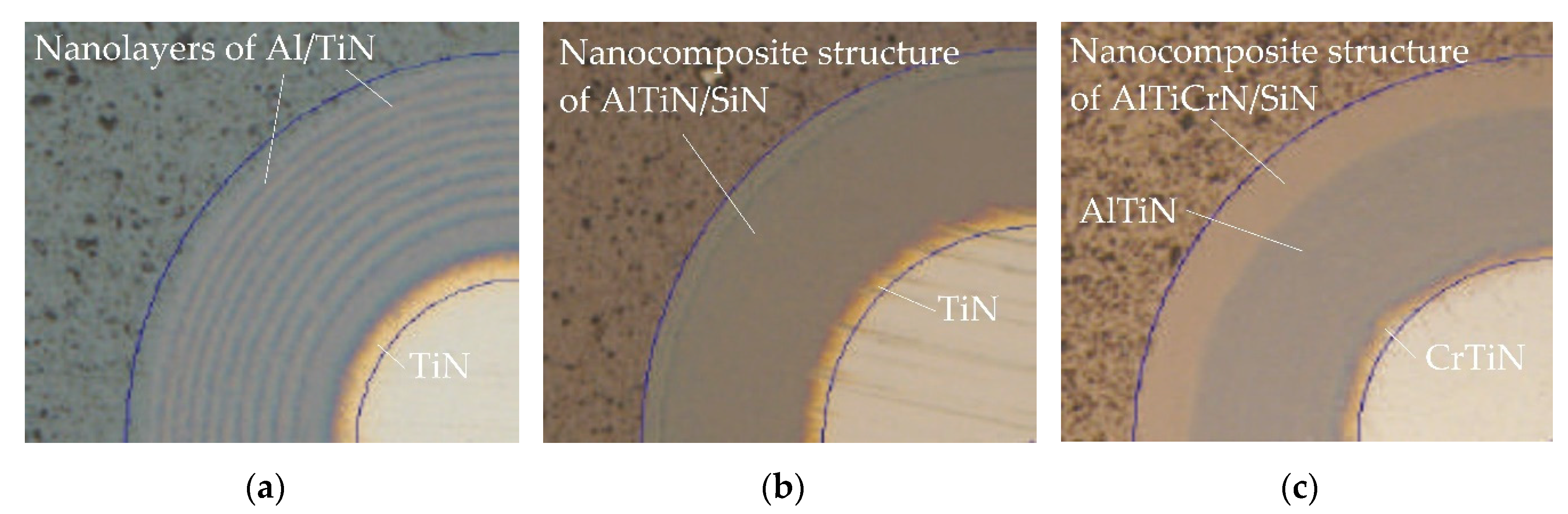
3.1. Surface Morphology and Microrelief
3.2. Physical and Mechanical Properties
3.3. Adhesion and Wear Resistance of End Mills
4. Discussion
5. Conclusions
Author Contributions
Funding
Acknowledgments
Conflicts of Interest
References
- An, Q.; Chen, J.; Tao, Z.; Ming, W.; Chen, M. Experimental investigation on tool wear characteristics of PVD and CVD coatings during face milling of Ti 6242S and Ti-555 titanium alloys. Int. J. Refract. Met. Hard Mater. 2019, 86, 105091. [Google Scholar] [CrossRef]
- Bandapalli, C.; Sutaria, B.M.; Prasad Bhatt, D.V.; Singh, K.K. Tool Wear Analysis of Micro End Mills—Uncoated and PVD Coated TiAlN AlTiN in High Speed Micro Milling of Titanium Alloy—Ti-0.3Mo-0.8Ni. Proc. CIRP 2018, 77, 626–629. [Google Scholar] [CrossRef]
- Shokrani, A.; Al-Samarrai, I.; Newman, S.T. Hybrid cryogenic MQL for improving tool life in machining of Ti-6Al-4V titanium alloy. J. Manuf. Process. 2019, 43, 229–243. [Google Scholar] [CrossRef]
- Huang, P.L.; Li, J.F.; Sun, J.; Zhou, J. Study on performance in dry milling aeronautical titanium alloy thin-wall components with two types of tools. J. Clean. Prod. 2014, 67, 258–264. [Google Scholar] [CrossRef]
- Huang, P.; Li, J.; Sun, J.; Ge, M. Milling force vibration analysis in high-speed-milling titanium alloy using variable pitch angle mill. Int. J. Adv. Manuf. Technol. 2012, 58, 153–160. [Google Scholar] [CrossRef]
- Wan, M.; Feng, J.; Zhang, W.H.; Yang, Y.; Ma, Y.C. Working mechanism of helix angle on peak cutting forces together with its design theory for peripheral milling tools. J. Mater. Proc. Technol. 2017, 249, 570–580. [Google Scholar] [CrossRef]
- Schoop, J.; Sales, W.F.; Jawahir, I.S. High speed cryogenic finish machining of Ti-6Al4V with polycrystalline diamond tools. J. Mater. Proc. Technol. 2017, 250, 1–8. [Google Scholar] [CrossRef]
- Jamil, M.; Khan, A.M.; Hegab, H.; Gupta, M.K.; Mia, M.; He, N.; Zhao, G.; Song, Q.; Liu, Z. Milling of Ti–6Al–4V under hybrid Al2O3-MWCNT nanofluids considering energy consumption, surface quality, and tool wear: A sustainable machining. Int. J. Adv. Manuf. Technol. 2020, 107, 4141–4157. [Google Scholar] [CrossRef]
- Zhang, M.; Zhang, D.; Geng, D.; Shao, Z.; Liu, Y.; Jiang, X. Effects of tool vibration on surface integrity in rotary ultrasonic elliptical end milling of Ti–6Al–4V. J. Alloys Compd. 2020, 821, 153266. [Google Scholar] [CrossRef]
- Mou, W.; Jiang, Z.; Zhu, S. A study of tool tipping monitoring for titanium milling based on cutting vibration. Int. J. Adv. Manuf. Technol. 2019, 104, 3457–3471. [Google Scholar] [CrossRef]
- Oh, W.-J.; Lee, C.-M. A study on laser assisted acute angle milling strategies and preheating distance. J. Manuf. Process. 2019, 44, 216–225. [Google Scholar] [CrossRef]
- Baptista, A.; Silva, F.; Porteiro, J.; Míguez, J.; Pinto, G. Sputtering Physical Vapour Deposition (PVD) Coatings: A Critical Review on Process Improvement and Market Trend Demands. Coatings 2018, 8, 402. [Google Scholar] [CrossRef]
- Ross, K.N.S.; Ganesh, M. Performance Analysis of Machining Ti-6Al-4V Under Cryogenic CO2 Using PVD-TiN Coated Tool. J. Fail. Anal. Prev. 2019, 19, 821–831. [Google Scholar] [CrossRef]
- Czettl, C.; Thurner, J.; Schleinkofer, U. Knowledge based coating design of CVD TiN-TiBN-TiB2 architecture. Int. J. Refract. Met. Hard. Mater. 2018, 71, 330–334. [Google Scholar] [CrossRef]
- Metel, A.; Grigoriev, S.; Melnik, Y.; Panin, V.; Prudnikov, V. Cutting tools nitriding in plasma produced by a fast neutral molecule beam. Jpn. J. Appl. Phys. 2011, 50, 08JG04. [Google Scholar] [CrossRef]
- Sahoo, P.; Patra, K. Mechanistic modeling of cutting forces in micro-end-milling considering tool run out, minimum chip thickness and tooth overlapping effects. Mach. Sci. Technol. 2019, 23, 407–430. [Google Scholar] [CrossRef]
- Sahoo, P.; Pratap, T.; Patra, K. A hybrid modelling approach towards prediction of cutting forces in micro end milling of Ti-6Al-4V titanium alloy. Int. J. Mech. Sci. 2019, 150, 495–509. [Google Scholar] [CrossRef]
- Sharif, S.; Ramli, A.S.; Said, A.Y.M.; Karim, Z.; Rahim, E.A.; Abdul Sani, A.S. Effect of Cutting Parameters on Tool Wear when Trochoidal Pocket Milling Ti6Al4V. Int. J. Integrated Eng. 2019, 11, 159–165. [Google Scholar] [CrossRef]
- Slicing and Trochoidal Milling. Available online: https://www.sandvik.coromant.com/en-gb/knowledge/milling/milling-holes-cavities-pockets/pages/slicing-trochoidal-milling.aspx (accessed on 24 May 2020).
- The ISCAR Reference Guide for Machining Titanium. Available online: https://www.iscar.ru/Catalogs/publication-2019/machining_titanium_05_2019.pdf (accessed on 24 May 2020).
- Otkur, M.; Lazoglu, I. Trochoidal milling. Int. J. Mach. Tools Manuf. 2007, 47, 1324–1332. [Google Scholar] [CrossRef]
- Da Silva, R.B.; MacHado, Á.R.; Ezugwu, E.O.; Bonney, J.; Sales, W.F. Tool life and wear mechanisms in high speed machining of Ti-6Al-4V alloy with PCD tools under various coolant pressures. J. Mater. Process. Technol. 2013, 213, 1459–1464. [Google Scholar] [CrossRef]
- Rao, B.; Dandekar, C.R.; Shin, Y.C. An experimental and numerical study on the face milling of Ti-6Al-4V alloy: Tool performance and surface integrity. J. Mater. Process. Technol. 2011, 211, 294–304. [Google Scholar] [CrossRef]
- Annoni, M.; Rebaioli, L.; Semeraro, Q. Thin wall geometrical quality improvement in micromilling. Int. J. Adv. Manuf. Technol. 2015, 79, 881–895. [Google Scholar] [CrossRef]
- Sadik, M.I.; Isakson, S. The role of PVD coating and coolant nature in wear development and tool performance in cryogenic and wet milling of Ti-6Al-4V. Wear 2017, 386, 204–210. [Google Scholar] [CrossRef]
- Bobzin, K. High-performance coatings for cutting tools. CIRP J. Manuf. Sci. Technol. 2017, 18, 1–9. [Google Scholar] [CrossRef]
- Fominski, V.Y.; Grigoriev, S.N.; Celis, J.P.; Romanov, R.I.; Oshurko, V.B. Structure and mechanical properties of W–Se–C/diamond-like carbon and W–Se/diamond-like carbon bi-layer coatings prepared by pulsed laser deposition. Thin Solid Films 2012, 520, 6476–6483. [Google Scholar] [CrossRef]
- Kuzin, V.; Grigoriev, S. Method of investigation of the stress-strain state of surface layer of machine elements from a sintered nonuniform material. Appl. Mech. Mater. 2014, 486, 32–35. [Google Scholar]
- Trindade, B.; Li, W.Z.; Fernandes, F.; Cavaleiro, A. Effect of Nb target power on the structure, mechanical properties, thermal stability and oxidation resistance of Cr–Al–Nb–N coatings. Surf. Coat. Technol. 2016, 285, 270–277. [Google Scholar] [CrossRef]
- Volosova, M.; Grigoriev, S.; Metel, A.; Shein, A. The role of thin-film vacuum-plasma coatings and their influence on the efficiency of ceramic cutting inserts. Coatings 2018, 8, 287. [Google Scholar] [CrossRef]
- Boxman, R.L.; Zhitomirsky, V.N.; Grimberg, I.; Rapoport, L.; Goldsmith, S.; Weiss, B.Z. Structure and hardness of vacuum arc deposited multi-component nitride coatings of Ti, Zr and Nb. Surf. Coat. Technol. 2000, 125, 257–262. [Google Scholar] [CrossRef]
- Santecchia, E.; Hamouda, A.M.S.; Musharavati, F.; Zalnezhad, E.; Cabibbo, M.; Spigarelli, S. Wear resistance investigation of titanium nitride-based coatings. Ceram. Int. 2015, 41, 10349–10379. [Google Scholar] [CrossRef]
- Chen, L.; Du, Y.; Wang, A.J.; Wang, S.Q.; Zhou, S.Z. Effect of Al content on microstructure and mechanical properties of Ti-Al-Si-N nanocomposite coatings. Int. J. Refract. Met. Hard Mater. 2009, 27, 718–721. [Google Scholar] [CrossRef]
- Sobol', O.V.; Andreev, A.A.; Grigoriev, S.N.; Volosova, M.A.; Gorban’, V.F. Vacuum-arc multilayer nanostructured TiN/Ti coatings: Structure, stress state, properties. Metal Sci. Heat Treat. 2012, 54, 28–33. [Google Scholar] [CrossRef]
- Grigoriev, S.; Metel, A. Plasma- and Beam-Assisted Deposition Methods. Nato Science Series, Series Ii: Mathematics, Physics and Chemistry; Nanostructured Thin Films and Nanodispersion Strengthened Coatings. NATO Science Series II: Mathematics, Physics and Chemistry; Voevodin, A.A., Shtansky, D.V., Levashov, E.A., Moore, J.J., Eds.; Springer: Dordrecht, The Netherlands, 2004; Volume 155, pp. 147–154. [Google Scholar] [CrossRef]
- Vereschaka, A.A.; Grigoriev, S.N.; Sitnikov, N.N.; Batako, A. Delamination and longitudinal cracking in multi-layered composite nano-structured coatings and their influence on cutting tool life. Wear 2017, 390, 209–219. [Google Scholar] [CrossRef]
- Vereschaka, A.A.; Grigoriev, S.N.; Vereschaka, A.S.; Popov, A.Y.; Batako, A.D. Nano-scale multilayered composite coatings for cutting tools operating under heavy cutting conditions. Proc. CIRP 2014, 14, 239–244. [Google Scholar] [CrossRef]
- Kohlscheen, J.; Bareiss, C. Effect of Hexagonal Phase Content on Wear Behaviour of AlTiN Arc PVD Coatings. Coatings 2018, 8, 72. [Google Scholar] [CrossRef]
- Siwawut, S.; Saikaew, C.; Wisitsoraat, A.; Surinphong, S. Cutting performances and wear characteristics of WC inserts coated with TiAlSiN and CrTiAlSiN by filtered cathodic arc in dry face milling of cast iron. Int. J. Adv. Manuf. Technol. 2018, 97, 3883–3892. [Google Scholar] [CrossRef]
- Volkhonskii, A.O.; Blinkov, I.V. Influence of deposition parameters of the Ti-Al-N/Zr-Nb-N-Cr-N multilayered nanostructured coating obtained by the arc-PVD method on their physicomechanical, tribological, and operational properties. Russ. J. Non Ferr. Metals 2012, 53, 259–265. [Google Scholar] [CrossRef]
- Fominski, V.Y.; Grigoriev, S.N.; Gnedovets, A.G.; Romanov, R.I. Pulsed laser deposition of composite Mo-Se-Ni-C coatings using standard and shadow mask configuration. Surf. Coat. Technol. 2012, 206, 5046–5054. [Google Scholar] [CrossRef]
- Vereschaka, A.A.; Volosova, M.A.; Grigoriev, S.N.; Vereschaka, A.S. Development of wear-resistant complex for high-speed steel tool when using process of combined cathodic vacuum arc deposition. Proc. CIRP 2013, 9, 8–12. [Google Scholar] [CrossRef]
- Grigoriev, S.N.; Melnik, Y.A.; Metel, A.S.; Panin, V.V.; Prudnikov, V.V. Broad beam source of fast atoms produced as a result of charge exchange collisions of ions accelerated between two plasmas. Instrum. Exp. Tech. 2009, 52, 602–608. [Google Scholar] [CrossRef]
- Grigoriev, S.N.; Metel', A.S.; Fedorov, S.V. Modification of the structure and properties of high-speed steel by combined vacuum-plasma treatment. Met. Sci. Heat Treat. 2012, 54, 8–12. [Google Scholar] [CrossRef]
- Liu, D.; Zhang, Y.; Luo, M.; Zhang, D. Investigation of Tool Wear and Chip Morphology in Dry Trochoidal Milling of Titanium Alloy Ti–6Al–4V. Materials 2019, 12, 1937. [Google Scholar] [CrossRef]
- Šajgalík, M.; Kušnerová, M.; Harničárová, M.; Valíček, J.; Czán, A.; Czánová, T.; Drbúl, M.; Borzan, M.; Kmec, J. Analysis and Prediction of the Machining Force Depending on the Parameters of Trochoidal Milling of Hardened Steel. Appl. Sci. 2020, 10, 1788. [Google Scholar] [CrossRef]
- Santhakumar, J.; Iqbal, M.U. Parametric Optimization of Trochoidal Step on Surface Roughness and Dish Angle in End Milling of AISID3 Steel Using Precise Measurements. Materials 2019, 12, 1335. [Google Scholar]
- Deng, Q.; Mo, R.; Chen, Z.C.; Chang, Z. An Analytical Approach to Cutter Edge Temperature Prediction in Milling and Its Application to Trochoidal Milling. Appl. Sci. 2020, 10, 1746. [Google Scholar] [CrossRef]
- Zagórski, I.; Kulisz, M.; Kłonica, M.; Matuszak, J. Trochoidal Milling and Neural Networks Simulation of Magnesium Alloys. Materials 2019, 12, 2070. [Google Scholar] [CrossRef] [PubMed]
- Wu, W.; Chen, W.; Yang, S.; Lin, Y.; Zhang, S.; Cho, T.Y.; Lee, G.H.; Kwon, S.C. Design of AlCrSiN multilayer and nanocomposite coating for HSS cutting tools. Appl. Surf. Sci. 2015, 351, 803–810. [Google Scholar] [CrossRef]
- Grigoriev, S.; Melnik, Y.; Metel, A. Broad fast neutral molecule beam sources for industrial-scale beam-assisted deposition. Surf. Coat. Technol. 2002, 156, 44–49. [Google Scholar] [CrossRef]
- Grigoriev, S.N.; Melnik, Y.A.; Metel, A.S.; Panin, V.V. A Compact Vapor Source of Conductive Target Material Sputtered by 3-keV Ions at 0.05-Pa Pressure. Instrum. Exp. Tech. 2009, 52, 731–737. [Google Scholar] [CrossRef]
- Metel, A.S.; Grigoriev, S.N.; Melnik, Y.A.; Bolbukov, V.P. Broad beam sources of fast molecules with segmented cold cathodes and emissive grids. Instrum. Exp. Tech. 2012, 55, 122–130. [Google Scholar] [CrossRef]
- Metel, A.S.; Grigoriev, S.N.; Melnik, Y.A.; Prudnikov, V.V. Glow discharge with electrostatic confinement of electrons in a chamber bombarded by fast electrons. Plasma Phys. Rep. 2011, 37, 628–637. [Google Scholar] [CrossRef]
- Volosova, M.A.; Grigoriev, S.N.; Ostrikov, E.A. Use of laser ablation for formation of discontinuous (discrete) wear-resistant coatings formed on solid carbide cutting tool by electron beam alloying and vacuum-arc deposition. Mech. Ind. 2016, 17, 720. [Google Scholar] [CrossRef]
- Metel, A.S. Ionization effect in cathode layers on glow-discharge characteristics with oscillating electrons. 1. Discharge with the hollow cathode. Zhurnal Tekhnicheskoi Fizikf 1985, 55, 1928–1934. [Google Scholar]
- Liang, S.C.; Chang, Z.C.; Tsai, D.C.; Lin, Y.C.; Sung, H.S.; Deng, M.J.; Shieu, F.S. Effects of substrate temperature on the structure and mechanical properties of (TiVCrZrHf) N coatings. Appl. Surf. Sci. 2011, 257, 7709–7713. [Google Scholar] [CrossRef]
- Yi, J.; Chen, K.; Xu, Y. Microstructure, Properties, and Titanium Cutting Performance of AlTiN–Cu and AlTiN–Ni Coatings. Coatings 2019, 9, 818. [Google Scholar] [CrossRef]
- Li, Y.; Zheng, G.; Cheng, X.; Yang, X.; Xu, R.; Zhang, H. Cutting Performance Evaluation of the Coated Tools in High-Speed Milling of AISI 4340 Steel. Materials 2019, 12, 3266. [Google Scholar] [CrossRef]
- Zhang, Z.; Chen, J.; He, G.; Yang, G. Fatigue and Mechanical Behavior of Ti-6Al-4V Alloy with CrN and TiN Coating Deposited by Magnetic Filtered Cathodic Vacuum Arc Process. Coatings 2019, 9, 689. [Google Scholar] [CrossRef]
- Krella, A.; Czyżniewski, A.; Gilewicz, A.; Gajowiec, G. Experimental Study of the Influence of Deposition of Multilayer CrN/CrCN PVD Coating on Austenitic Steel on Resistance to Cavitation Erosion. Coatings 2020, 10, 487. [Google Scholar] [CrossRef]
- Niu, Y.; Jiao, F.; Zhao, B.; Gao, G. Investigation of Cutting Force in Longitudinal-Torsional Ultrasonic-Assisted Milling of Ti-6Al-4V. Materials 2019, 12, 1955. [Google Scholar] [CrossRef]
- Jarfors, A.E.W.; Castagne, S.J.; Danno, A.; Zhang, X. Tool Wear and Life Span Variations in Cold Forming Operations and Their Implications in Microforming. Technologies 2017, 5, 3. [Google Scholar] [CrossRef]
- Schulz, M.J.; Kelkar, A.D.; Sundaresan, M.J. (Eds.) Nanohardness Testing. In Nanoengineering of Structural, Functional, and Smart Materials, 1st ed.; CRC Press: Boca Raton, FL, USA, 2005; pp. 545–551. [Google Scholar] [CrossRef]
- Oliver, W.C.; Pharr, G.M. An improved technique for determining hardness and elastic modulus using load and displacement sensing indentation. J. Mater. Res. 1992, 7, 1564–1583. [Google Scholar] [CrossRef]
- Grigoriev, S.; Volosova, M.; Fyodorov, S.; Lyakhovetskiy, M.; Seleznev, A. DLC-coating Application to Improve the Durability of Ceramic Tools. J. Mater. Eng. Perform. 2019, 28, 4415–4426. [Google Scholar] [CrossRef]
- Mishra, S.; Chaubey, A.; Mandal, A. Effect of Heat Treatment on the Microstructure of Mg-4Al-Nd Alloys. Technologies 2017, 5, 23. [Google Scholar] [CrossRef]
- Fedorov, S.V.; Ostrikov, E.A.; Mustafaev, E.S.; Hamdy, K. The formation of the cutting tool microgeometry by pulsed laser ablation. Mech. Ind. 2018, 19, 703. [Google Scholar] [CrossRef]
- Grigoriev, S.N.; Metel, A.S.; Melnik, Y.A.; Volosova, M.A. Equipment and Technology for Combined Ion–Plasma Strengthening of Cutting Tools. Machines 2018, 6, 58. [Google Scholar] [CrossRef]
- Sousa, V.F.C.; Silva, F.J.G. Recent Advances on Coated Milling Tool Technology—A Comprehensive Review. Coatings 2020, 10, 235. [Google Scholar] [CrossRef]
- Caliskan, H.; Panjan, P.; Kurbanoglu, C. 3.16 Hard Coatings on Cutting Tools and Surface Finish. Compr. Mater. Finish. 2017, 3, 230–242. [Google Scholar]
- Vopát, T.; Sahul, M.; Haršáni, M.; Vortel, O.; Zlámal, T. The Tool Life and Coating-Substrate Adhesion of AlCrSiN-Coated Carbide Cutting Tools Prepared by LARC with Respect to the Edge Preparation and Surface Finishing. Micromachines 2020, 11, 166. [Google Scholar] [CrossRef]
- Selvam, L.; Murugesan, P.K.; Mani, D.; Natarajan, Y. Investigation of AlCrN-Coated Inserts on Cryogenic Turning of Ti-6Al-4V Alloy. Metals 2019, 9, 1338. [Google Scholar] [CrossRef]
- Ren, Z.; Qu, S.; Zhang, Y.; Li, X.; Yang, C. Machining Performance of TiAlN-Coated Cemented Carbide Tools with Chip Groove in Machining Titanium Alloy Ti-6Al-0.6Cr-0.4Fe-0.4Si-0.01B. Metals 2018, 8, 850. [Google Scholar] [CrossRef]
- Swain, N.; Venkatesh, V.; Kumar, P.; Srinivas, G.; Ravishankar, S.; Barshilia, H.C. An experimental investigation on the machining characteristics of Nimonic 75 using uncoated and TiAlN coated tungsten carbide micro-end mills. CIRP J. Manuf. Sci. Technol. 2017, 16, 34–42. [Google Scholar] [CrossRef]
- Durmaz, Y.M.; Yildiz, F. The wear performance of carbide tools coated with TiAlSiN, AlCrN and TiAlN ceramic films in intelligent machining process. Ceram. Int. 2018, 45, 3839–3848. [Google Scholar] [CrossRef]


| Ti | Al | Zr | V | Mo | Si | N | Fe | C | H | O |
|---|---|---|---|---|---|---|---|---|---|---|
| 85.15–91.4 | 5.5–7 | 1.5–2.5 | 0.8–2.5 | 0.5–2 | Up to 0.15 | Up to 0.05 | Up to 0.25 | Up to 0.1 | Up to 0.015 | Up to 0.15 |
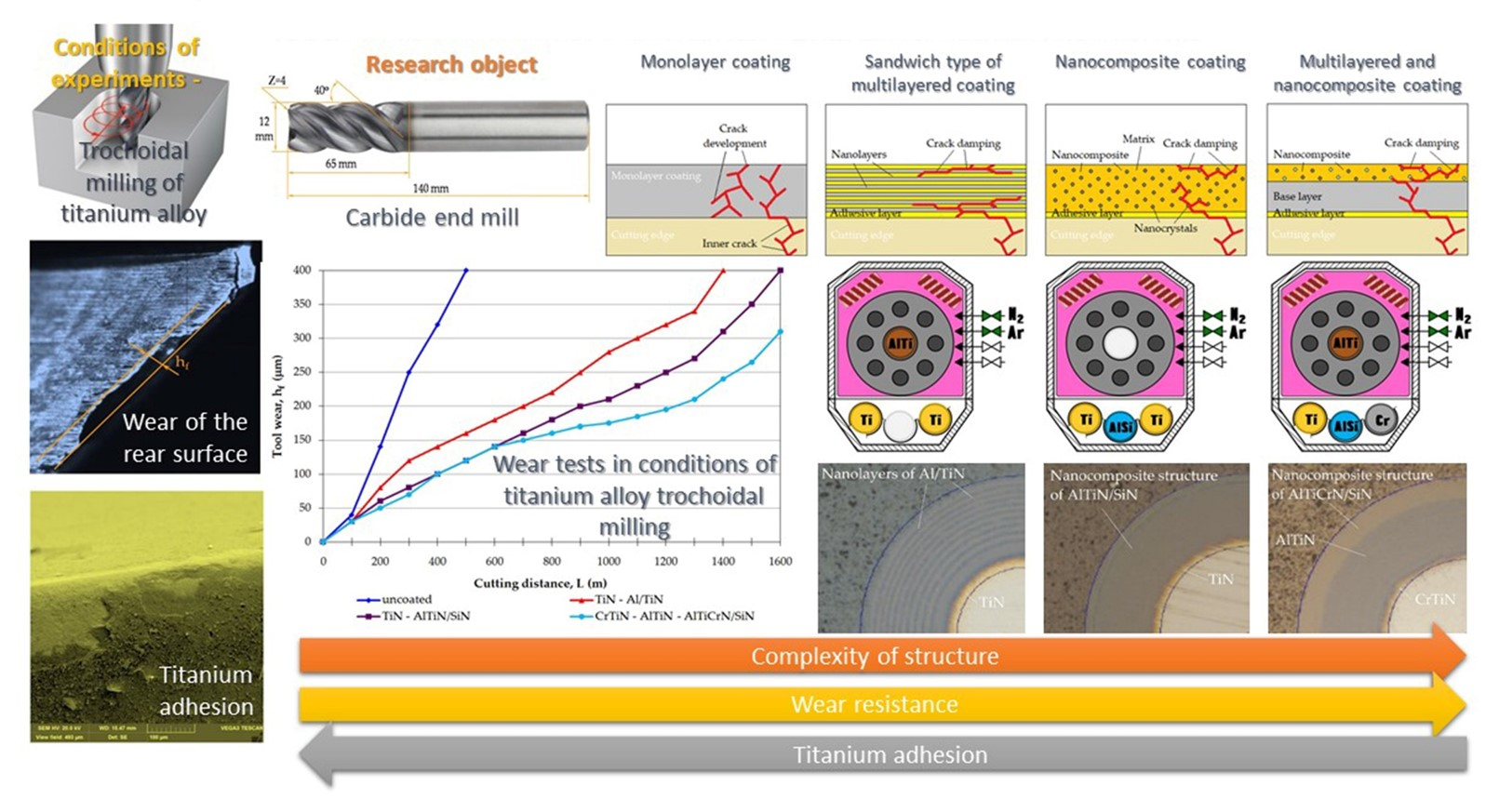
| No. | Multi-Component Coating Composition | Microhardness H (GPa) | Elastic Modulus E (GPa) | H/E Ratio |
|---|---|---|---|---|
| 1 | TiN–Al/TiN (multilayered “sandwich”) | 33 ± 1 | 362 ± 8 | 0.091 |
| 2 | TiN–AlTiN/SiN (nanocomposite) | 43 ± 2 | 412 ± 6 | 0.104 |
| 3 | CrTiN–AlTiN–AlTiCrN/SiN (multilayered nanocomposite) | 41 ± 1 | 340 ± 6 | 0.120 |
© 2020 by the authors. Licensee MDPI, Basel, Switzerland. This article is an open access article distributed under the terms and conditions of the Creative Commons Attribution (CC BY) license (http://creativecommons.org/licenses/by/4.0/).
Share and Cite
Volosova, M.A.; Fyodorov, S.V.; Opleshin, S.; Mosyanov, M. Wear Resistance and Titanium Adhesion of Cathodic Arc Deposited Multi-Component Coatings for Carbide End Mills at the Trochoidal Milling of Titanium Alloy. Technologies 2020, 8, 38. https://doi.org/10.3390/technologies8030038
Volosova MA, Fyodorov SV, Opleshin S, Mosyanov M. Wear Resistance and Titanium Adhesion of Cathodic Arc Deposited Multi-Component Coatings for Carbide End Mills at the Trochoidal Milling of Titanium Alloy. Technologies. 2020; 8(3):38. https://doi.org/10.3390/technologies8030038
Chicago/Turabian StyleVolosova, Marina A., Sergey V. Fyodorov, Stepan Opleshin, and Mikhail Mosyanov. 2020. "Wear Resistance and Titanium Adhesion of Cathodic Arc Deposited Multi-Component Coatings for Carbide End Mills at the Trochoidal Milling of Titanium Alloy" Technologies 8, no. 3: 38. https://doi.org/10.3390/technologies8030038
APA StyleVolosova, M. A., Fyodorov, S. V., Opleshin, S., & Mosyanov, M. (2020). Wear Resistance and Titanium Adhesion of Cathodic Arc Deposited Multi-Component Coatings for Carbide End Mills at the Trochoidal Milling of Titanium Alloy. Technologies, 8(3), 38. https://doi.org/10.3390/technologies8030038