Article

Engineering Micropatterned Surfaces for Controlling the Evaporation Process of Sessile Droplets

by
Navid Kashaninejad
1,*,
Nam-Trung Nguyen
1,* and
Weng Kong Chan
2
1
Queensland Micro- and Nanotechnology Centre, Nathan Campus, Griffith University, 170 Kessels Road, Brisbane, QLD 4111, Australia
2
School of Mechanical and Aerospace Engineering, Nanyang Technological University, Singapore 639798, Singapore
*
Authors to whom correspondence should be addressed.
Technologies 2020, 8(2), 29; https://doi.org/10.3390/technologies8020029
Submission received: 20 April 2020 / Revised: 12 May 2020 / Accepted: 17 May 2020 / Published: 19 May 2020
(This article belongs to the Section Innovations in Materials Processing)

Abstract

:
Controlling the evaporation process of a droplet is of the utmost importance for a number of technologies. Also, along with the advances of microfabrication, micropatterned surfaces have emerged as an important technology platform to tune the wettability and other surface properties of various fundamental and applied applications. Among the geometrical parameters of these micropatterns, it is of great interest to investigate whether the arrangement of the patterns would affect the evaporation process of a sessile liquid droplet. To address this question, we fabricated four microhole arrays with different arrangements, quantified by the parameter of “eccentricity”. The results suggested that, compared to smooth substrates, the evaporation mode was not only affected by engineering the microhole arrays, but also by the eccentricity of these micropatterns. The values of contact angle hysteresis (CAH) were used to quantify and test this hypothesis. The CAH could partially explain the different evaporation modes observed on the microhole arrays with zero and non-zero values of eccentricity. That is, on microhole arrays with zero eccentricity, CAH of water droplets was comparatively low (less than 20 ° ). Consistently, during the evaporation, around 60% of the life span of the droplet was in the mixed evaporation mode. Increasing the eccentricity of the microhole arrays increases the values of CAH to above 20 ° . Unlike the increasing trend of CAH, the evaporation modes of sessile droplets on the microhole array with non-zero values of eccentricity were almost similar. Over 75% of the life span of droplets on these surfaces was in constant contact line (CCL) mode. Our findings play a significant role in any technology platform containing micropatterned surfaces, where controlling the evaporation mode is desirable.

1. Introduction

Droplet evaporation is an important process that frequently occurs in daily life and various industries. In particular, the analysis of evaporating sessile droplets is crucial for a range of industrial applications such as spray coating [1], spray cooling [2], inkjet printing [3], pesticide spraying [4], biotechnologies such as the production of DNA microarrays [5], cell culture [6,7], microfluidics [8,9,10], liquid marbles [11] and microdroplet molding for nanopatterning [12]. Free evaporation of water droplets in still air can be considered as a pure diffusion process. Using the analogy between diffusive flux and electrostatic potential, Maxwell [13] showed that the evaporation rate is a linear function of the droplet radius, diffusion coefficient, D f , and the concentration difference of the vapor in the proximity of the surface of the droplet, C s , and far from the droplet, C . However, the presence of the solid surface can restrict the droplet diffusive flux and subsequently alter the droplet evaporation. These surface effects can be assessed by considering the influence of the surface wettability on the evaporation process of sessile droplets.
According to the pinning and depinning process of the contact line of an evaporating droplet sitting on a smooth solid surface, three modes of evaporation are possible: constant contact line (CCL) mode, constant contact angle (CCA) mode, and the mixed mode. In the CCL mode, while the droplet is pinned to the surface, the contact angle decreases as the droplet evaporates. In the CCA mode, decreasing the volume of the evaporating droplet reduces the contact line, while the contact angle remains constant. Finally, in the mixed-mode, which usually occurs at the end of the evaporation process, both contact angle and contact line diminish as the droplet evaporates. Picknett and Bexon [14] incorporated an additional term, f ( θ ) , which was a function of the surface contact angle, θ , into the Maxwell evaporation model to more realistically describe the evaporation rate of spherical droplets. Their model was readily applicable to predict the total lifetime as well as the volume change of the droplet for the CCA mode. Rowan et al. conducted experimental and analytical analyses of droplet evaporation on hydrophilic polymeric surfaces [15]. Using a two-parameter spherical cap model, the team showed that the mass loss in the CCL mode is proportional to the height of the droplet rather than its radius. Extending this work, Erbil and Meric [16] developed mathematical expressions based on the three-parameter geometry of the ellipsoidal cap to describe the evaporation process of a large droplet on polymeric surfaces. More details of the models were developed by other researchers such as Erbil et al. [17] for the CCA mode, and Bourges-Monnier and Shanahan [18] for the CCL and the mixed modes, and were thoroughly reviewed [19]. Song et al. [20] presented the empirical formulations to fit the experimental data of temporal volume variation of evaporating droplets on surfaces with different wetting conditions.
Evaluating the evaporation behavior on non-wetting surfaces, typically with initial contact angles larger than 90 ° , is of great importance due to their applications in microfluidics and lab-on-a-chip systems. On the hydrophobic surfaces made of polydimethylsiloxane (PDMS) and Teflon, Yu et al. [21] observed that after an initial CCL mode, the evaporation mode changed to the CCA, followed by the mixed-mode at the final stage of the evaporation. They derived the theoretical expressions for both CCL and CCA modes based on the assumption of a uniform concentration gradient. Surface roughness is another parameter that affects the wettability as well as the evaporating mechanism of droplets. Originally inspired by nature, advances in micro/nanofabrication techniques made it possible to engineer the desired micro/nano-size patterns to control surface wetting conditions. These micropatterned (super)hydrophobic surfaces have been finding application in many areas. Controlling the evaporation modes on these surfaces is crucially important in both academia and industry sectors. McHale et al. [22] evaluated the evaporating behavior of water droplets on micropillar surfaces made of SU-8 photoresist. The team observed another evaporation mode corresponding to the case where the droplets collapse from Cassie-Baxter state [23], with droplets on top of the pillar, to the Wenzel state [24], with droplets penetrating the air pockets. When the droplets were in the Cassie-Baxter condition, the initial droplet mode was CCL, followed by a stepwise fashion contact line receding. After the transition to Wenzel state, the CCL was the dominant mode of the evaporation. Zhang et al. conducted a droplet evaporation analysis of hierarchical natural and biomimetic micropatterned surfaces [25]. Gelderblom et al. investigated the evaporation process of a water droplet on carbon nanofiber (CNF) surfaces with an initial contact angle larger than 150 ° [26]. The team found that CCL was the dominant mode of evaporation during the entire lifetime of the droplet. A scaling analysis based on the theoretical work of Popov [27] showed that the variation of the droplet mass is independent of the droplet size and is only a function of the contact angle. Chen et al. [28] investigated the evaporation dynamics by systematically changing the pillar spacing from 10   μ m 40   μ m at the fixed pillar length and height. All three modes of CCL, CCA, and the Cassie-Baxter-to-Wenzel mixed modes were observed consecutively. However, it was found that by increasing the pillar spacing, the transition to the mixed Wenzel state occurred. It was also theoretically shown that as the size of the droplet becomes comparable to the pillar size, the importance of the line becomes more pronounced. The relationship between the pinning force and the surface morphology was evaluated with an array of PDMS spherical caps [29]. Xu and Choi evaluated the evaporation kinetics of water as well as gold colloid droplets on superhydrophobic surfaces [30]. The authors fabricated three different micropatterned surfaces, including pillars lines, and wells at a fixed air fraction. The team showed that evaporation modes on the flat and micropatterned surfaces could be significantly different and vary based on the pattern configurations.
In addition to the typical geometrical parameters of the micropatterned surfaces, such as pillar height, length, and spacing, we showed that the arrangement of the pattern, quantified by the term “eccentricity”, might also influence the surface static/dynamic wetting [31], three-phase contact line shapes [32], and drag reduction ability of the microchannels fabricated from such micropatterned surfaces [33]. These results suggest that altering the eccentricity of the micropatterned surfaces might also influence the droplet evaporation modes. To our best knowledge, investigation of the droplet evaporation process as a function of surface morphology and eccentricity has not been conducted in the literature, and is, therefore, the main objective of the current work. We evaluated the evaporation process of a deionized (DI) water droplets on smooth surfaces and microhole-patterned surfaces. We systematically varied the eccentricity of the microholes. We then investigated the evolution of the contact radius of the droplets. The results were compared and discussed in terms of the contact angle hysteresis (CAH) and pinning force behaviors of the micropatterned surfaces.

2. Materials and Methods

2.1. Design of Micropatterned Surfaces

We designed and fabricated microhole arrays on the PDMS substrate. The eccentricity values, ε , of the micropatterns were systematically varied, while other geometrical parameters of these square-shaped microhole arrays, such as spacing D and lengt   L , were kept constant. The eccentricity of the micropatterns was normalized with respect to the pattern pitch, λ = L + D . That is, ε * = ε / λ , which is the normalized eccentricity and was systematically varied from 0 to 0.75, as schematically shown in Figure 1.

2.2. Fabrication of Micropatterned Surfaces

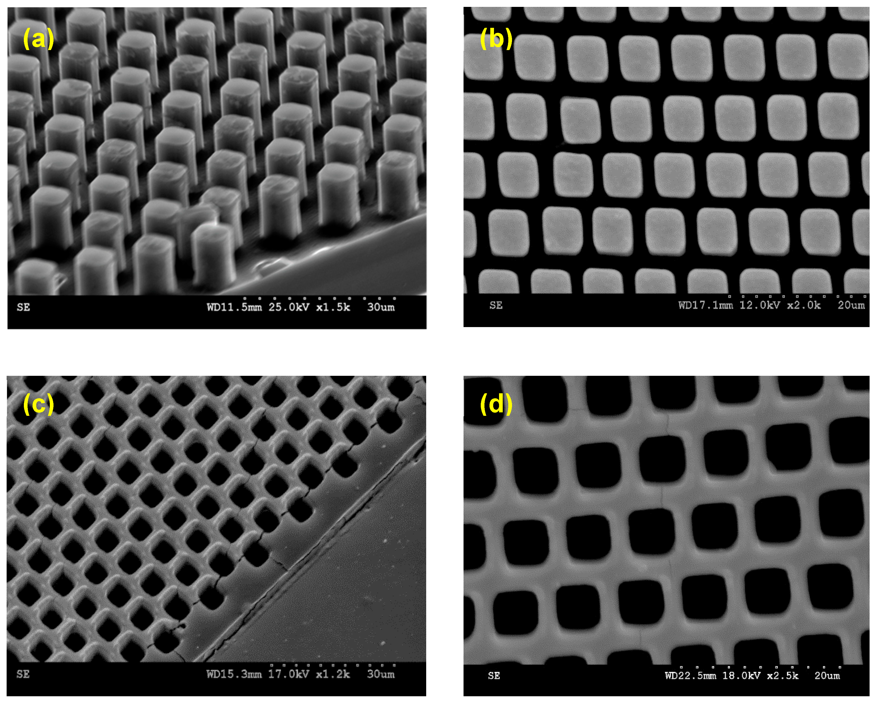
The micropillar arrays were first fabricated on a silicon wafer using standard photolithography followed by deep reactive ion etching (DRIE), as thoroughly explained in our previous publication [31]. Briefly, the micropattern structures were designed in L-edit software and subsequently patterned on a glass mask. After uniformly coating AZ4620 positive photoresist on the silicon wafer, the UV light with an intensity of 8.3 mW/cm2 and a duration of 170 s was used to transfer the micropatterns from the glass mask onto the silicon wafer coated with the photoresist. After thoroughly washing away the UV-exposed regions of the photoresist, the micropatterns were transferred on silicon. Finally, DRIE was used to create less than 10 µm-height pillars on the silicon. Figure 2a,b show the scanning electron microscopy (SEM) images of the micropillar arrays.
Using the silicon wafer with micropillar arrays as a master mold, the microhole arrays were transferred on PDMS using the standard micro-molding technique [33]. The surface of the silicon wafer with micropillar arrays was first treated with trichloromethylsilane (TCMS, Sigma-Aldrich, Singapore) to make it hydrophilic. Next, 10:1 (wt%) of PDMS was mixed with its curing agent and degassed in a vacuum chamber for 30 min. Then, the PDMS mixture was poured on the TCMS-treated silicon wafers with the pillar arrays. After further degassing and curing in an oven at 70 ° C for 2 h, the PDMS substrate with transferred microhole arrays was peeled off from the silicon wafer. Figure 2c,d show the SEM images of the fabricated microhole arrays. Table 1 summarizes the detailed parameters of the fabricated microhole structures.

2.3. Monitoring the Droplet Evaporation

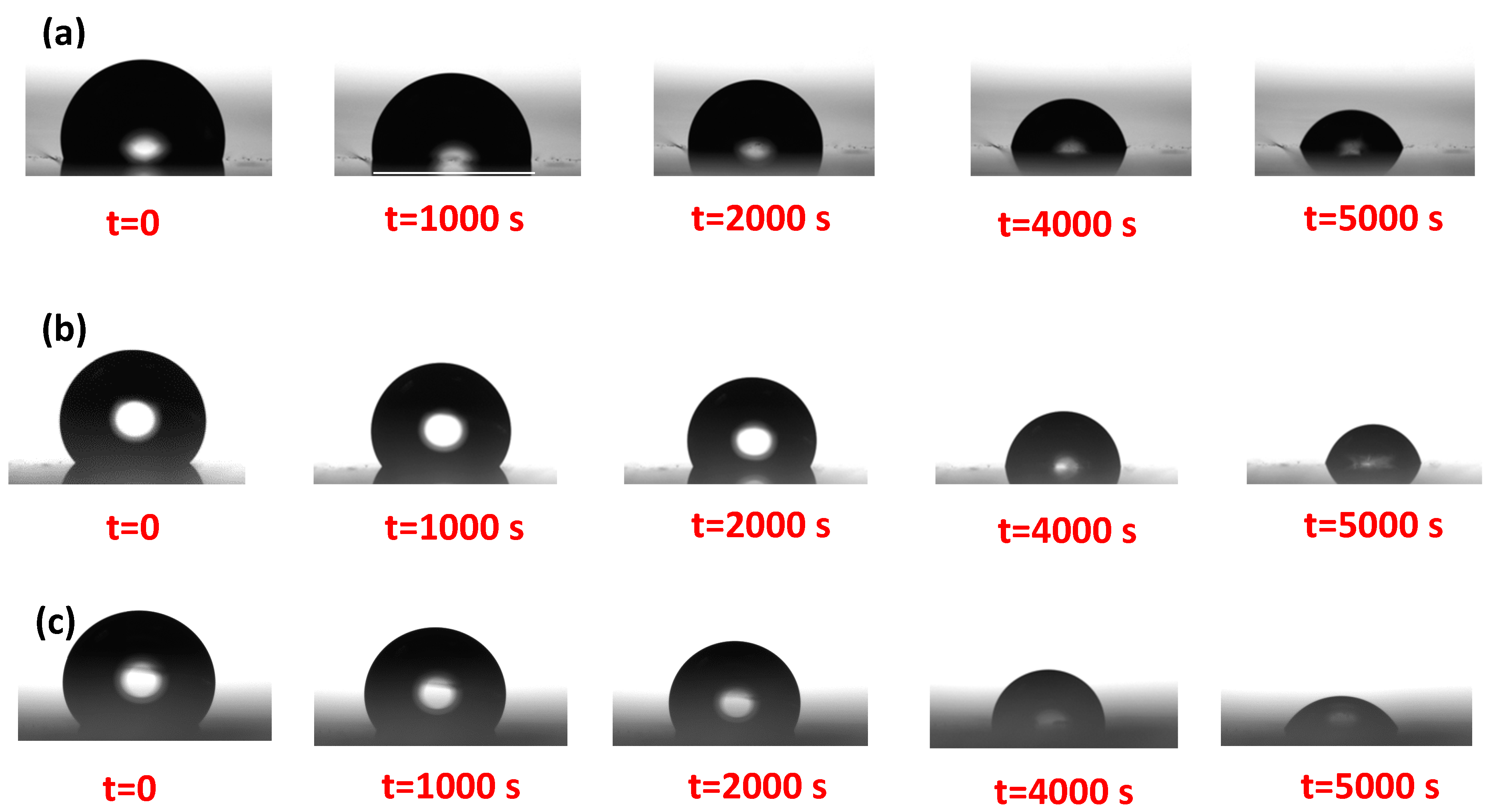
Several techniques are available for capturing the evaporation process of the droplets, including video microscopy and mass sensing using electronic microbalances and microcantilevers [34]. Here, we monitored the evaporation dynamics of the droplets using an optical tensiometer (Theta Attension, BiolinScientific, Espoo, Finland). First, the instrument was optically calibrated at a fixed magnification using a spherical calibrating ball with a diameter of 4.00018   mm , provided by the manufacturer. On each sample, a small volume droplet ( 7.5   μ L 9.5   μ L ) was gently dispensed in an air-conditioned environment. According to the installed thermo-hydrograph (Ota Keiki Seisakusho Co., Osaka, Japan), the average room temperature and relative humidity were 23   ° C and 48 % , respectively. Using the “multi-frame mode” of the tensiometer with a frame interval of 1 s and 7200 total frame numbers, the droplet was left to freely evaporate on the surface samples for 2 h. We observed that the total time of 2 h was much longer than the evaporation lifetime, t f , for all surface samples. Each experiment was conducted at least three times, and the average values were reported at a 95% confidence interval. For the selected volume range, the maximum droplet radius, R m , is smaller than 1.5   mm , and the related Bond number, B o = ρ g R m 2 / γ w , where ρ and γ w are the density and surface tension of water at room temperature, respectively, was less than 0.3. We can conclude that the effect of gravity is negligible compared to the surface tension, and thus the droplet shape can be approximated using a spherical cap geometry. In such a case, measuring two parameters of the droplet, such as droplet base radius, r b , and contact angle, θ , leads to other parameters such as droplet height, h , and volume, V , based on geometrical relationships [16]. In this work, the captured images of the droplet were optically processed every 20 s to quantify these geometrical parameters until the droplet evaporated completely, at the droplet lifetime t f . Figure 3 shows a representative image sequence of the evaporation of the DI droplets on smooth and micropatterned surfaces. The microhole arrays evidently change the evaporation modes. Qualitatively comparing the droplet profiles in Figure 3b,c indicates that changing the arrangement of the microhole arrays, which is quantified by the normalized eccentricity, can alter the evaporation mode. More quantitative comparisons will be presented and discussed in the next section.

3. Results and Discussions

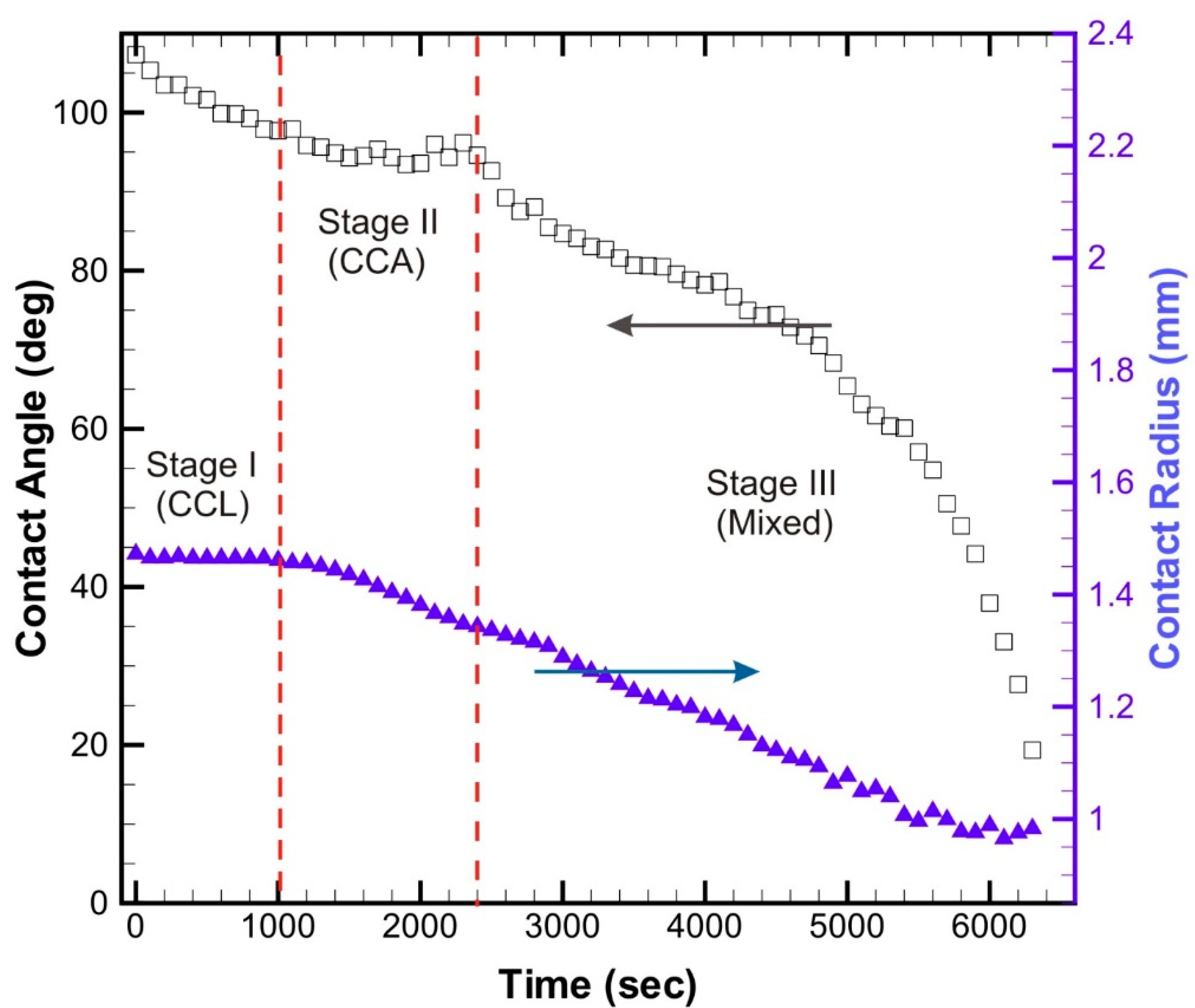
We first investigated the trend of droplet evaporation on a smooth PDMS surface. Figure 4 shows the corresponding time-related distributions of the contact angle and contact radius of the droplet with an initial volume of 9.3   μ L . In the first 1000 s, the droplet is pinned to the surface, and the contact angle decreases almost linearly. During this initial time, the percentage decrease in the contact radius is less than 0.7%, while the contact angle decreases by more than 10%.
After the contact angel reaches a value of 97 ° , the contact line starts to recede. In the next 1200 s, the contact angle is fluctuating around a constant value while the contact line recedes, implying a quasi-static CCA mode. In the final stage of evaporation, both contact angle and contact radius shrink over time, corresponding to the mixed mode of evaporation. This trend of evaporation is qualitatively consistent with the previous observations on smooth planar hydrophobic surfaces [21,29]. It is more meaningful to define the normalized time, t * = t / t f , and normalized contact radius, r b * = r b , t / r b 0 , where r b , t is the base contact radius of the droplet at any instant t and r b 0 is the initial droplet contact radius at time t = 0 . In the case of droplet evaporation on the smooth PDMS surface, the lifetime of the droplet is approximately t f = 6300 s, and the initial droplet contact radius r b 0 = 1.47   mm . Thus, we can conclude that 15% of a droplet’s lifetime is in CCL mode, t * = 0.15 , around 20% is in CCA mode, and the rest in the mixed evaporation mode.
Next, we evaluated the evaporation of DI water droplets on microhole arrays. Figure 5 shows the temporal variation of the normalized contact radius of the droplets on microhole arrays with four different values of eccentricity, ε * = 0 ,   0.25 ,   0.5 and 0.75 . The results show the two modes of evaporation on microhole arrays: the CCL mode and the mixed mode.
On the microhole arrays with zero eccentricity, approximately 40% of the lifetime of the droplet is in the CCL mode, while the rest is in a mixed-mode of evaporation. For non-zero values of the eccentricity of microhole arrays, over 75% of the lifetime of the droplet is in CCL mode. The mixed-mode of evaporation on the microhole arrays with non-zero eccentricity only appears during the late stage of evaporation. Interestingly, we did not observe the CCA mode during the evaporation of DI water droplets on such microhole arrays. Moreover, no significant change in the evaporation mode was observed among the microhole arrays with different non-zero values of eccentricity, i.e., ε * = 0.25 ,   0.5 and 0.75 . The reason for the similar evaporation behavior of water droplets on the micropatterned surfaces with ε * = 0.25 and ε * = 0.75 can be related to the arrangement of the microhole structures. In other words, two micropatterned surfaces with normalized eccentricity ε * = 0.25 and ε * = 0.75 possess mirror symmetry of each other. Therefore, the morphology of the microhole structures on these two surfaces is the same. As confirmed in Figure 5, there are no significant differences in evaporation modes and lifetimes of water droplets on these surfaces.
The above results suggest that the contact line tends to pin on the microhole arrays during the evaporation process. Pinning of the contact line is correlated with contact angle hysteresis (CAH) of the droplets on a solid surface. CAH shows the difference between advancing and receding contact angles and is a good indication of how a droplet rolls on a solid surface. In other words, droplets with low CAH tend to roll easily on a solid surface, while those with large CAH stick to the solid surface. In the case of evaporation, CCL mode usually corresponds to the surfaces with high CAH, while CCA mode dominates on surfaces with low CAH [35]. Furthermore, the droplet evaporation rate is slower on a surface with low CAH as a result of generating a local saturation vapor near the contact line of such surfaces. Therefore, it is crucial to evaluate the CAH of the droplets to justify the evaporation mechanism.
Previously, we quantified the CAH of DI water droplets on microhole arrays [33,36]. Of great importance, we observed that although the static contact angle on such microhole arrays was over 140 ° , their CAH was comparatively high. The exact values of the CAH of these microhole arrays are summarized in Table 2.
As the results suggest, the CAH of microhole arrays is a function of eccentricity. Increasing the eccentricity of the microhole arrays increases the CAH of the droplets. Microhole arrays with ε* = 0.25 and ε* = 0.75 are the mirror images of each other, as seen in Figure 1. Thus, the values of CAH on both surfaces are comparable. As explained thoroughly in our previous publication [31], the dependency of CAH on the eccentricity can be justified by considering the contact line tension in the modified version of the Cassie-Baxter equation [37]. The radius of the curvature of three-phase contact line (TPCL) can be changed by varying the eccentricity of the micropatterned surfaces while keeping the void area fraction constant. On the other hand, higher values of CAH imply higher pinning forces of the TPCL. In micropatterned surfaces with high pinning of TPCL, the dominant mode of evaporation is the CCL mode [22]. These observations are consistent with our experimental results shown in Figure 5.
In other words, the CAH of the microhole arrays with zero eccentricity is less than those of the microhole arrays with non-zero eccentricity. Consistently, during the evaporation, most of the life span of the droplet is in the mixed evaporation mode (around 60%, Figure 5). However, increasing the eccentricity of the microhole arrays also increases CAH (Table 2). Increasing the CAH implies that the droplets tend to pin on the micropatterned surfaces during the evaporation. However, this trend is not valid for microhole arrays with ε* = 0.5. Although the CAH on ε* = 0.5 is higher than those of ε* = 0.25 and ε* = 0.75 (Figure 5), the evaporation mode of this microhole array is not significantly different from the other two microhole arrays with non-zero values of eccentricity. This inconsistency can be explained by considering a threshold for the CAH (here is on the order of 20 ° ). Above this critical CAH, the pinning force of TPCL is large enough and would not be significantly changed by varying the eccentricity of the micropatterned surfaces. This phenomenon opens up a further research gap that requires a more systematic investigation of the effect of the eccentricity of micropatterned surfaces on the evaporation mode. Considering the current geometries of the microhole arrays (Table 1), it seems that the TPCL does not significantly change during the evaporation process of droplets on the microhole arrays with non-zero values of eccentricity.

4. Conclusions

Controlling the evaporation is of great importance for many technological and industrial applications, such as inkjet printing, spray cooling, and anti-fogging/anti-icing coatings. In the present study, we showed that micropatterned surfaces could alter the evaporation mode of a sessile droplet. Of particular interest, we demonstrated that the arrangement of the micropattern surfaces, quantified by the term “eccentricity”, could affect the evaporation mode. We fabricated four PDMS microhole arrays with different values of eccentricity and evaluated the evaporation mode of the DI water droplets on these substrates. We observed three modes of evaporation on a smooth PDMS substrate: CCA, CCL, and mixed evaporation. However, on micropatterned surfaces, only two modes of evaporation, i.e., CCL and mixed modes, were detectable. Moreover, while over 75% of the lifetime of droplets on the microhole arrays with non-zero eccentricity was in the CCL mode, this value was around 40% for the droplets surrounded by microhole arrays with zero eccentricity. This observation was partially correlated with the trend of CAH on the microhole arrays. However, unlike the higher value of CAH of the microhole arrays with ε* = 0.5, the evaporation mode was similar to those two microhole arrays with non-zero values of eccentricity. The exact mechanism of evaporation of the micropatterned surfaces with non-zero values of eccentricity needs to be further investigated in future works.
The general findings of the current study can be beneficial for applications where controlling the evaporation mode is necessary on micropatterned surfaces. For instance, in thin-film particle deposition on solid surfaces, where liquid droplets are encapsulated with small solid particles and leave the specific patterns on the solid surface upon drying, the CCL mode of evaporation is the preferred one. Accordingly, the results of this study suggest that in such an application (also known as the “coffee ring effect”), using micropatterned surfaces with non-zero eccentricity is more appropriate, as most of the lifetime of the droplets would be in the CCL mode.

Author Contributions

Conceptualization, N.K., N.-T.N. and W.K.C.; methodology, N.K.; software, N.K.; validation, N.K.; data curation, N.K.; writing—original draft preparation, N.K.; writing—review and editing, N.K. and N.-T.N.; visualization, N.K.; supervision, N.-T.N. and W.K.C. All authors have read and agreed to the published version of the manuscript.

Funding

This research received no external funding.

Acknowledgments

The samples were fabricated at the Griffith University site of the Queensland node of the Australian National Fabrication Facility, a company established under the National Collaborative Research Infrastructure Strategy to provide nano and microfabrication facilities for Australia’s researchers.

Conflicts of Interest

The authors declare no conflict of interest.

References

  1. Majumder, M.; Rendall, C.; Li, M.; Behabtu, N.; Eukel, J.A.; Hauge, R.H.; Schmidt, H.K.; Pasquali, M. Insights into the physics of spray coating of SWNT films. Chem. Eng. Sci. 2010, 65, 2000–2008. [Google Scholar] [CrossRef]
  2. Jia, W.; Qiu, H.H. Experimental investigation of droplet dynamics and heat transfer in spray cooling. Exp. Therm. Fluid Sci. 2003, 27, 829–838. [Google Scholar] [CrossRef]
  3. Lim, T.; Han, S.; Chung, J.; Chung, J.T.; Ko, S.; Grigoropoulos, C.P. Experimental study on spreading and evaporation of inkjet printed pico-liter droplet on a heated substrate. Int. J. Heat Mass Transf. 2009, 52, 431–441. [Google Scholar] [CrossRef]
  4. Yu, Y.; Zhu, H.; Ozkan, H.; Derksen, R.; Krause, C. Evaporation and deposition coverage area of droplets containing insecticides and spray additives on hydrophilic, hydrophobic, and crabapple leaf surfaces. Trans. ASAE (Am. Soc. Agric. Eng.) 2009, 52, 39. [Google Scholar] [CrossRef]
  5. Dugas, V.; Broutin, J.; Souteyrand, E. Droplet evaporation study applied to DNA chip manufacturing. Langmuir 2005, 21, 9130–9136. [Google Scholar] [CrossRef]
  6. Moghadas, H.; Saidi, M.S.; Kashaninejad, N.; Nguyen, N.-T. A high-performance polydimethylsiloxane electrospun membrane for cell culture in lab-on-a-chip. Biomicrofluidics 2018, 12, 024117. [Google Scholar] [CrossRef] [PubMed]
  7. Barisam, M.; Saidi, M.S.; Kashaninejad, N.; Nguyen, N.-T. Prediction of necrotic core and hypoxic zone of multicellular spheroids in a microbioreactor with a u-shaped barrier. Micromachines 2018, 9, 94. [Google Scholar] [CrossRef] [Green Version]
  8. Moghadas, H.; Saidi, M.S.; Kashaninejad, N.; Nguyen, N.-T. Challenge in particle delivery to cells in a microfluidic device. Drug Deliv. Transl. Res. 2018, 8, 830–842. [Google Scholar] [CrossRef] [Green Version]
  9. Kashaninejad, N.; Chan, W.K.; Nguyen, N.-T. Fluid mechanics of flow through rectangular hydrophobic microchannels. In Proceedings of the ASME 2011 9th International Conference on Nanochannels, Microchannels, and Minichannels, Edmonton, AB, Canada, 19–22 June 2011; Volume 1, pp. 647–655. [Google Scholar] [CrossRef]
  10. Rostami, P.; Kashaninejad, N.; Moshksayan, K.; Saidi, M.S.; Firoozabadi, B.; Nguyen, N.-T. Novel approaches in cancer management with circulating tumor cell clusters. J. Sci. Adv. Mater. Devices 2019, 4, 1–18. [Google Scholar] [CrossRef]
  11. Vadivelu, R.; Kashaninejad, N.; Sreejith, K.R.; Bhattacharjee, R.; Cock, I.; Nguyen, N.-T. Cryoprotectant-free freezing of cells using liquid marbles filled with hydrogel. ACS Appl. Mater. Interfaces 2018, 10, 43439–43449. [Google Scholar] [CrossRef]
  12. Cheng, W.; Park, N.; Walter, M.T.; Hartman, M.R.; Luo, D. Nanopatterning self-assembled nanoparticle superlattices by moulding microdroplets. Nat. Nano 2008, 3, 682–690. [Google Scholar] [CrossRef] [PubMed]
  13. Maxwell, J. Diffusion, Collected Scientific Papers; Encyclopedia Britannica: Cambridge, UK, 1877. [Google Scholar]
  14. Picknett, R.G.; Bexon, R. The evaporation of sessile or pendant drops in still air. J. Colloid Interface Sci. 1977, 61, 336–350. [Google Scholar] [CrossRef]
  15. Rowan, S.M.; Newton, M.I.; McHale, G. Evaporation of microdroplets and the wetting of solid surfaces. J. Phys. Chem. 1995, 99, 13268–13271. [Google Scholar] [CrossRef]
  16. Erbil, H.Y.; Meric, R.A. Evaporation of sessile drops on polymer surfaces:  Ellipsoidal cap geometry. J. Phys. Chem. B 1997, 101, 6867–6873. [Google Scholar] [CrossRef]
  17. Erbil, H.Y.; McHale, G.; Newton, M.I. Drop evaporation on solid surfaces:  Constant contact angle mode. Langmuir 2002, 18, 2636–2641. [Google Scholar] [CrossRef]
  18. Bourges-Monnier, C.; Shanahan, M.E.R. Influence of evaporation on contact angle. Langmuir 1995, 11, 2820–2829. [Google Scholar] [CrossRef]
  19. Erbil, H.Y. Evaporation of pure liquid sessile and spherical suspended drops: A review. Adv. Colloid Interface Sci. 2012, 170, 67–86. [Google Scholar] [CrossRef]
  20. Song, H.; Lee, Y.; Jin, S.; Kim, H.Y.; Yoo, J.Y. Prediction of sessile drop evaporation considering surface wettability. Microelectron. Eng. 2011, 88, 3249–3255. [Google Scholar] [CrossRef]
  21. Yu, Y.-S.; Wang, Z.; Zhao, Y.-P. Experimental and theoretical investigations of evaporation of sessile water droplet on hydrophobic surfaces. J. Colloid Interface Sci. 2012, 365, 254–259. [Google Scholar] [CrossRef] [Green Version]
  22. McHale, G.; Aqil, S.; Shirtcliffe, N.J.; Newton, M.I.; Erbil, H.Y. Analysis of droplet evaporation on a superhydrophobic surface. Langmuir 2005, 21, 11053–11060. [Google Scholar] [CrossRef]
  23. Cassie, A.; Baxter, S. Wettability of porous surfaces. Trans. Faraday Soc. 1944, 40, 546–551. [Google Scholar] [CrossRef]
  24. Wenzel, R. Resistance of solid surfaces to wetting by water. Ind. Eng. Chem. 1936, 28, 988–994. [Google Scholar] [CrossRef]
  25. Zhang, X.; Tan, S.; Zhao, N.; Guo, X.; Zhang, X.; Zhang, Y.; Xu, J. Evaporation of sessile water droplets on superhydrophobic natural lotus and biomimetic polymer surfaces. ChemPhysChem 2006, 7, 2067–2070. [Google Scholar] [CrossRef] [PubMed]
  26. Gelderblom, H.; Marín, Á.G.; Nair, H.; van Houselt, A.; Lefferts, L.; Snoeijer, J.H.; Lohse, D. How water droplets evaporate on a superhydrophobic substrate. Phys. Rev. E 2011, 83, 026306. [Google Scholar] [CrossRef] [Green Version]
  27. Popov, Y.O. Evaporative deposition patterns: Spatial dimensions of the deposit. Phys. Rev. E 2005, 71, 036313. [Google Scholar] [CrossRef] [Green Version]
  28. Chen, X.; Ma, R.; Li, J.; Hao, C.; Guo, W.; Luk, B.L.; Li, S.C.; Yao, S.; Wang, Z. Evaporation of droplets on superhydrophobic surfaces: Surface roughness and small droplet size effects. Phys. Rev. Lett. 2012, 109, 116101. [Google Scholar] [CrossRef] [Green Version]
  29. Zhang, C.; Zhu, X.; Zhou, L. Morphology tunable pinning force and evaporation modes of water droplets on PDMS spherical cap micron-arrays. Chem. Phys. Lett. 2011, 508, 134–138. [Google Scholar] [CrossRef]
  30. Xu, W.; Choi, C.-H. Effects of surface topography and colloid particles on the evaporation kinetics of sessile droplets on superhydrophobic surfaces. J. Heat Transf. 2012, 134, 051022–051027. [Google Scholar] [CrossRef]
  31. Kashaninejad, N.; Chan, W.K.; Nguyen, N.-T. Eccentricity effect of micropatterned surface on contact angle. Langmuir 2012, 28, 4793–4799. [Google Scholar] [CrossRef] [Green Version]
  32. Kashaninejad, N.; Nguyen, N.-T.; Chan, W.K. The three-phase contact line shape and eccentricity effect of anisotropic wetting on hydrophobic surfaces. Soft Matter 2013, 9, 527–535. [Google Scholar] [CrossRef] [Green Version]
  33. Kashaninejad, N.; Nguyen, N.-T.; Chan, W.K. Eccentricity effects of microhole arrays on drag reduction efficiency of microchannels with a hydrophobic wall. Phys. Fluids 2012, 24, 112004–112018. [Google Scholar] [CrossRef] [Green Version]
  34. Lee, M.; Lee, D.; Jung, N.; Yun, M.; Yim, C.; Jeon, S. Evaporation of water droplets from hydrophobic and hydrophilic nanoporous microcantilevers. Appl. Phys. Lett. 2011, 98, 013107. [Google Scholar] [CrossRef] [Green Version]
  35. Kulinich, S.A.; Farzaneh, M. Effect of contact angle hysteresis on water droplet evaporation from super-hydrophobic surfaces. Appl. Surf. Sci. 2009, 255, 4056–4060. [Google Scholar] [CrossRef]
  36. Kashaninejad, N. Fluid Mechanics of Flow through Microchannels; Nanyang Technological University: Singapore, 2013. [Google Scholar]
  37. Drelich, J.; Miller, J.D. Modification of the cassie equation. Langmuir 1993, 9, 619–621. [Google Scholar] [CrossRef]
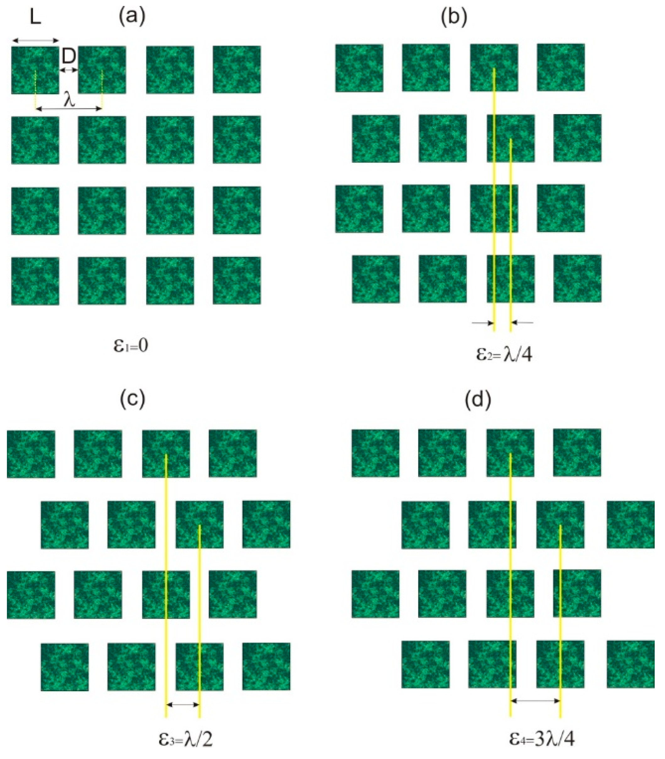
Figure 1. Schematic representation of the investigated micropatterned surfaces at fixed pattern spacings, D , with varying eccentricity: (a) ε * = 0 ; (b) ε * = 0.25 ; (c) ε * = 0.50 ; (d) ε * = 0.75 . As evident from the figure, microhole arrays with ε * = 0.25 and ε * = 0.75 are mirror images of each other.
Technologies 08 00029 g001
Figure 2. Representative SEM images of the fabricated micropatterned surfaces. (a,b) Silicon micropillar arrays (cross-sectional and top views) fabricated using DRIE technique; (c,d) PDMS microhole arrays (cross-sectional and top views) replicated from the silicon micropillar master molds.
Technologies 08 00029 g002
Figure 3. Image sequences of evaporating sessile DI water droplets ( 7.5   μ L 9.5   μ L ) on: (a) smooth PDMS; (b) microhole arrays with zero eccentricity ( ε * = 0 ) ; and (c) microhole arrays with ε * = 0.75 . The figure shows the first 5000 s time of the evaporation of sessile droplets under room temperature ( 23   ° C ) and 48 % relative humidity.
Technologies 08 00029 g003
Figure 4. A time history of the droplet contact angle and contact radius on the smooth PDMS surface. Three different modes of evaporation are observable: constant contact line (CCL), constant contact angle (CCA), and mixed-mode (where neither contact line nor contact angle is constant during the course of evaporation).
Technologies 08 00029 g004
Figure 5. Temporal variations of the contact radius of the sessile DI water droplets with volumes of 7.5   μ L 9.5   μ L on microhole arrays with the different arrangement (quantified by normalized eccentricity). The presented results are the average values of three experiments, with a 95% confidence interval. To better interpret the results, the contact radius of the droplets at any instant was normalized by the initial contact radius of the same droplet. Also, the time was normalized by the lifetime t f of the droplet.
Technologies 08 00029 g005
Table 1. Detailed dimensions of the geometrical parameters of the fabricated microhole surfaces.
L   ( μ m ) D   ( μ m ) ε   ( μ m ) ε * = ε / λ
2.560,2,4,60, 0.25, 0.5, 0.75
Table 2. The values of contact angle hysteresis (CAH) of water droplets on the fabricated microhole arrays.
ε * 00.250.50.75
CAH 17 ° ± 2 ° 26 ° ± 2 ° 34 ° ± 3 ° 25 ° ± 2 °