Abstract
The design of additive manufacturing processes, especially for batch production in industrial practice, is of high importance for the propagation of new additive manufacturing technology. Manual redesign procedures of the additive manufactured parts based on discrete measurement data or numerical meshes are error prone and hardly automatable. To achieve the required final accuracy of the parts, often, various iterations are necessary. To address these issues, a data-driven geometrical compensation approach is proposed that adapts concepts from forming technology. The measurement information of a first calibration cycle of manufactured parts is the basis of the approach. Through non-rigid transformations of the part geometry, a new shape for the subsequent additive manufacturing process was derived in a systematic way. Based on a purely geometrical approach, the systematic portion of part deviations can be compensated. The proposed concept is presented first and was applied to a sample fin-shaped part. The deviation data of three manufacturing cycles was utilised for validation and verification.
1. Introduction
A central, key technology in the future will be additive manufacturing (AM) [1]. Opportunities are arising in combination with ongoing digitisation and cross-linking between production and design in line with industry 4.0. For certain components this will allow one to avoid costly and time-consuming production processes, such as the manufacturing of moulds and tools. An increase in flexibility and the production of individualised products containing complex structures without additional effort go hand in hand. In this way, AM can make a significant contribution to mastering the complexity in the production process associated with the rapidly increasing number of variants [2].
However, along with all of the opportunities AM processes offer, a comprehensive transfer to mass production is nowhere in sight. Central hurdles for the application in serial production are above all, the cost-related general conditions (high material costs in combination with an insufficient ratio of plant costs to productivity) and the high manual effort in the process chain due to the lack of physical and digital line integration. This current lack of the integration of AM processes in conventional production environments is due to the specifics of AM processes, such as batch production, and the currently low degree of automation in the peripheral systems, such as component handling, quality measurement and transport chains. On the component level, one major critical point in mass production is accuracy and reproducibility. In AM processes, deviations between the nominal and the actual parts are primarily caused by the highly complex thermo-mechanical conditions leading to high gradients and high temperatures, for example. This significantly limits the use and the associated potential of AM processes for in series production [3].
2. State of the Art
When considering the dimensional quality of manufactured components, the systematic and stochastic portions of the deviations have to be carefully separated. Varying environmental conditions, material fluctuations, tribology, and changing thermo-mechanical boundary conditions are typical sources of stochastic errors. It is impossible to completely eliminate the stochastic portion in real applications and direct elimination is hardly possible. To cope with stochastic phenomena, process robustness, reasonable component design and the suitable definitions of tolerances are necessary. The systematic deviations can be related to identifiable causes and possess unique, unidirectional characteristics. For that reason, systematic deviations can be addressed by geometric compensation. For a separation of both deviation types, a sufficient number of measurements is necessary.
2.1. Causes for Geometrical Deviations in Additive Manufacturing
Due to the complexity of the process chain from the CAD model to the finished component, geometric deviations can occur at different points in the manufacturing process. These can be divided into the following error categories [4]:
- Deviations in data preprocessing;
- Errors during material processing;
- Machine errors;
- Stochastic errors.
In laser powder bed fusion (L-PBF), each layer is two-dimensional. The three-dimensional component is, thus, created step-by-step by joining individual layers of the same thickness along the Z coordinate. For this purpose, mathematical layer information is extracted from the digital 3D data set during pre-processing. This results in deviations during the creation of a discrete mesh (usually .STL). In addition, layer-by-layer construction can result in steps in a component, since the smallest possible resolution in the Z-direction is the layer thickness [4,5].
During processing, the powder is heated by a laser to a temperature above its melting temperature in order to bond the particles through phase transformation. There is a risk of thermal stresses due to an inhomogeneous temperature distribution in the build chamber. As a result, distortions occur in the component, as the material shrinks inhomogeneously during cooling, resulting in thermally induced stresses. Dimensional deviations resulting from material shrinkage are dependent on the geometry of the respective component [6,7].
Based on temperature measurements in an SLS machine, a significant temperature gradient in the x-y plane of a layer was determined. From this it can be concluded that the material shrinkage of a geometry additionally depends on its x and y-positions in the build chamber [6]. The dimensional accuracy in the x-y plane of a layer depends directly on the scanning system used by the AM system and its ability to move the laser beam along the desired path [8]. Such machine errors, on the other hand, are measurable and can be compensated to a certain extent in order to minimise their effect on the end product to an acceptable minimum. In addition to the factors already mentioned, despite an identical processing environment, quality fluctuations can occur between the end products, the exact cause of which cannot be defined, so they are, therefore, regarded as stochastic errors. Of all these factors, the temperature-induced shrinkage of the material is the main cause of inaccuracies in the end product [4,8].
2.2. Classical Methods to Compensate for Deviations in Additive Manufacturing
In the literature, different methods have been found to counter geometry deviations in the component by conventional means. However, these are usually limited to one specific error. In their work, Pham et al. analysed various factors that influence the accuracy of additive manufactured components. This began with the generation of the STL file. The chord height and the angle control have a big influence on the accuracy. Some of these error sources can also be avoided by using alternative data formats [4,8,9].
During further processing from 3D to layer information (slicing), discretisation errors occur, which are mainly due to the z-direction resolution, which is limited to one layer in thickness [10]. These effects can, however, be reduced by various algorithms; for example, by adjusting the layer thickness [11]. In addition, the orientation of the parts in the build chamber can be adjusted. Masood et al. describe in their research, the possibility of minimising the error caused by the step effect by adjusting the orientation in the build chamber. The best possible orientation can be calculated on the basis of the minimum volumetric error. This leads to an improvement of the accuracy and the surface quality of the component by minimising the effects of the stair tread effect [12].
In order to prevent geometric deviations due to residual stresses in the component, heat treatments are used to reduce mechanical stresses in the component. This prevents stresses from being released and dimensional deviations from occurring in one of the subsequent processing stages, such as separation from the construction platform. Reference [13] In addition, thermal distortion is influenced by the scanning strategy and scanning time and can be improved by adjusting them. References [14,15,16] Kamat and Pei analytically calculated deformations due to residual stresses in parts with internal channels, which can be used to compensate for deformations [17]. To compensate for shrinkage effects, different scaling factors are applied to the individual 2D layers. Furthermore, a compensation of the laser diameter can be achieved by an offset in the 2D planes [4,18,19].
2.3. Geometrical Deviation Compensation in Additive Manufacturing
Due to interacting factors, such as material shrinkage, geometric complexity, quality fluctuations and machine faults and inaccuracies, it is challenging to predict and control the extent of dimensional deviations. The straightforward way to compensate for deviations is currently to use a constant scaling factor across a part to calculate material shrinkage. Alternatively, different scaling factors can be applied to individual sections in the CAD model. It is assumed that the dimensional deviations occur evenly in the individual sections. However, this assumption is often not legitimate due to the complexity of some geometries, and this can lead to transfer effects, among other things [20].
Huang et al. deal with the compensation of dimensional deviations in the x-y plane and define various quality standards that minimise volume and surface deviations [20,21].
In addition, initial work has been done to use pre-deformation to compensate for dimensional deviations in selective laser beam melting. This involves simulating thermal distortion in the component using a finite element calculation, and then pre-deforming the CAD model against the expected deviations [22,23,24]. Zhu et al. proposed a statistical shape analysis, which is trained with data obtained by simulation and can predict geometrical deviations for similar parts [25]. Furthermore, they proposed a compensation method for the layers of the sliced part [26]. Schmutzler et al. compared a simulation-based pre-deformation to a deviation compensation in theory, which is based on previous manufactured iterations, for a cantilever geometry. They showed that the simulation-based compensation converged to the desired geometry within three iterations [27].
3. Hypothesis
Geometrical accuracy has always been one of the main objectives in component manufacturing. The established manufacturing processes, therefore, have a variety of approaches that address this problem. In forming technology, two systematic approaches to deviation compensation are the displacement adjustment method and the stress-based adjustment method [28,29]. The stress-based method uses measured deviations to calculate a certain stress state on the target geometry. This stress state is reversed and is used as a boundary condition to deform the forming tool. The result of the deformation is the compensated forming tool. The displacement adjustment method works similarly. The measured deviations are directly reversed and used for the geometrical adaptation of the forming tool. Both methods have been used successfully in different applications. The stress-based adjustment methods seem to perform better for processes dominated by a global deformation pattern—sheet metal forming, for example, where the displacement adjustment method tends to be suitable for local compensation, as with bulk forming.
In AM, no tools are needed for manufacturing, but a manufacturing geometry has to be provided to the AM system. We proposed that this manufacturing geometry could be seen as a forming tool in a geometrical compensation sense. We further proposed that the displacement adjustment method, which directly incorporates the deviation data, is a suitable method for AM, because of its incremental characteristics.
In this paper, the objective was to prove those hypotheses. Therefore, a general geometrical compensation procedure based on the displacement adjustment method is suggested for AM to capture the problem of accuracy and reproducibility also with regard to an implementation in production lines. The compensation scheme is shown using a SLS process.
4. Materials and Methods
For the investigation in this paper, a SLS process is used to apply the conducted general geometrical compensation procedure. In the following subsections, the parts created, manufacturing steps and further processing are presented in detail.
4.1. Specimen and Manufacturing
A sample part was designed to show the effectiveness of the compensation algorithm. Figure 1 depicts the whole job. The fin-shaped geometry of the component was chosen specifically to boost thermal deviations. A total of 27 parts were positioned in the build chamber in three rows with nine parts each. We measured and compensated the blue coloured parts –. The light blue parts were measured but not compensated and served as a reference to their compensated direct neighbour to study the reproducibility of the process. For the digitisation of the components, the structured white light scanning device GOM ATOS II 400 (GOM, Braunschweig, Germany) was utilised. For each component, approximately 15 frames had to be acquired. With the setup we used, a resolution of 0.05 mm was achieved. The test specimens were fabricated using an EOS Formiga P100 (EOS, Krailing, Germany) in combination with polyamide 12 (EOS PA2200, Krailing, Germany). The powder we used had a 50/50 ratio of new and recycled powder. The chosen layer thickness was 0.1 mm. The job was positioned in the centre of the build platform with the standard offset of six millimetres in the z plane. The temperature of the process chamber was set to 172 degrees Celsius. The material-dependent scaling for the jobs was (X:3.086%; Y:3.019%; Z(0):2.2%; Z(300):1.6%). These machine parameters were kept constant for all jobs.
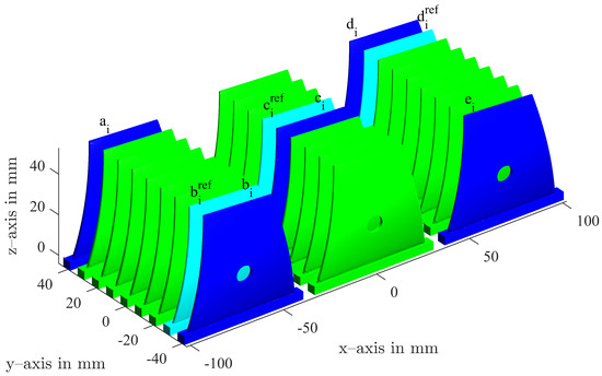
Figure 1.
Stacking of the components in the build chamber. Blue components were measured and compensated; cyan components were measured for reference and not compensated.
4.2. Compensation Algorithm
The compensation strategy was based on a framework proposed for bulk forming processes [30,31]. The compensation approach was fully driven by geometrical data, which, in principle, ensures general validity and scale invariance. In Figure 2 the flow chart for the compensation procedure is shown (forming in the upper half and the adaptation of AM in the lower half). Each process originates from the part design and the target geometry, which could be provided in any form; for example, as a CAD-design or reverse engineering measurement object. In case of forming processes a forming tool geometry is derived, which is close to the negative of the target geometry, but usually is divided into an upper and a lower tool part due to the uni-axial working direction of the presses. The active surfaces of the forming tool in the closed state show a certain transformation of the target geometry’s surface with the same topology. In the surface generation process (centre of Figure 2), this transformation, also called compensation, is deduced through the iterative tool redesign. Based on the target geometry for AM manufacturing, a discrete AM manufacturing geometry was determined based on the part design. This step corresponds to the generation of active tool surfaces in forming processes. Since AM is an incremental process, no physical tool is necessary, but an active closed surface is required, which is a building instruction for the AM system. It is transferred to the AM system for initial manufacturing. As an alternative, the framework is also capable of handling data in a numerical simulation framework. Whether part manufacturing, numerical analysis or both should used, depends on different process and part specific characteristics and attendant circumstances. Both from real manufacturing or numerical results, a final workpiece geometry was achieved and evaluated. The deviation data of the component compared to the target geometry served as input data for the systematic compensation. As a result, an updated AM manufacturing geometry is provided. This surface, in the sense of forming, “forms” the part, in the AM manufacturing environment. More abstract, in both manufacturing processes, surfaces have to be generated based on the target geometry, from which the actual manufacturing process result is controlled.

Figure 2.
Flow chart of the compensation process for determining a suitable manufacturing geometry for AM in comparison to the forming tool compensation approach.
The purely geometric approach assumes that all physical causes for deviations occurring during the manufacturing process are included in the systematic portion of the component shape. Hence, different physical boundary conditions have no effects on the general procedure. For example, different materials or processing temperatures can be treated in the same way. The approach also allows one, for example, to incorporate additional processing steps, such as heat treatments or machining. Material properties and environmental conditions are implicitly contained in the approach through the measurement data. The three key aspects pointed out in [31] in the context of bulk forming, reduce to two key aspects that also arise in AM for an efficient and effective implementation of the compensation procedure:
- Identification of the stochastic portion of the deviations;
- Automated and structured modification of manufacturing geometries.
The problem of finding a suitable manufacturing geometry presents as an inverse problem under stochastic conditions. Hence, the design process is built in an iterative manner. A certain number of iterations i need to be passed, as shown in Figure 2. The manufacturing geometry leads to a workpiece geometry . With a predefined reference coordinate system and the target geometry , the deviations can be derived. It is assumed that the deviation values are small compared to the component dimension. Hence, a non-rigid transformation between the target shape and the workpiece shape can be deduced. Additionally the manufacturing geometry is supposed to be a non-rigid transformation of the the target geometry . The idea of the geometrical compensation is to use the information of the non-rigid transformations to derive a new manufacturing geometry in a recursive fashion by using
The factor weighs the compensation term. In its easiest form, is scalar, but in principle, depending on the topological structure of , tensor-valued values are possible, leading to anisotropic compensations. Working with transformations of the target geometry is beneficial for computational reasons, since the same topology is ensured for straight forward calculations. In the present paper, the transformations are based on the target surface normals, which means that the measurement information can be directly used to build the transformations. The transformation in this case reads
At the beginning of the compensation process, an initial manufacturing geometry has to be defined, either based on experience, numerical analysis or simply the target geometry. After the first run, the geometric adjustment and stochastic phenomena in turn influence the entire AM process again, in the sense of the inverse problem, which could call for another iteration to achieve the desired tolerances.
In this paper, the target geometry is represented by a surface triangulation, as in common in AM. Based on the node coordinates and the connectivity list, a straightforward application of the transformations and is possible.
5. Results and Discussion
5.1. Geometrical Deviation in the Calibration and Compensation Cycles
In the calibration cycle (index 0), all 27 components in the build chamber were produced with the target geometry. In Figure 3 and Figure 4, the first rows with index 0 show seven measured parts with their respective positions in the build chamber in Figure 1. Two main geometrical errors can be observed in the measured parts. There is a volume error due to the shrinkage of the material, and the upper right edge of the fin is distorted. It is evident that no optimal, universal compensation for all components is possible, due to the influence of the position in the build chamber. Hence, a unique compensation was calculated for each of the compensated parts –.
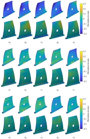
Figure 3.
Compensated components for the calibration cycle (0) and two compensation cycles (1 and 2). The positions on the building platform of the parts a-e are detailed in Figure 1.
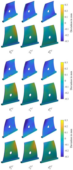
Figure 4.
Reference components without compensation for the calibration cycle (0) and two compensation cycles (1 and 2). The positions on the building platform of the parts - are detailed in Figure 1.
The results of the first compensation cycle are shown in the second row of Figure 3 with part numbers –. For part numbers –, the compensation reduced the geometrical deviation significantly. was not improved. Analysing the calibration cycle (), already is an outlier in the area of the upper-right corner. The compensation was calculated to this deviation and did not improve the accuracy. After further investigation, a finishing error was detected. There was still loose powder on the part in this area, which emulated a thicker part to the measuring system. Hence, the compensation led to a thinner part in .
The second compensation cycle (index 2) showed minor geometrical improvements for –. For , a minor deviation increase was measured, while was improved significantly. This shows that this compensation process is quite robust regarding process outliers, since in the next compensation cycle they can be corrected without manual interaction. The limit of the compensation is reached when the statistical deviations are in the same order of magnitude as the deterministic deviations. The minor increase in deviation for shows that this limit is possibly reached after two compensation cycles. In Figure 4, the results of the reference components, which were not compensated, can be analysed. The parts show minor changes from one cycle to the next as well. This is due to the statistical deviations.
Comparing cycles 0 and 2, the compensated parts were significantly improved in terms of geometrical accuracy. Furthermore, the parts were more homogeneous and the influence of the position in the build chamber was diminished. In order to quantify this improvement and to analyse the limits of this method, the deviations were numerically analysed; see the next section.
5.2. Evolution of the Part Deviations
In Figure 5, the evolution of the mean absolute error and the evolution of the standard deviation are shown over the three iterations. For the reference parts (, and in Figure 1) the mean absolute error and the standard deviation remains almost constant, which is in accordance with the impression of Figure 4. For all compensated parts, an enhancement in the mean absolute error and the standard deviation was achieved. The process outlier is also clearly visible in the evolution of the mean absolute error, which stayed higher after cycle 1 but improved significantly in cycle 2. In Figure 5, another outlier with respect to standard deviation in cycle 1 can be seen, which is part . The high standard deviation in cycle 1 finally led to the increased mean absolute error of part in cycle 2.

Figure 5.
Evolution of the mean absolute error and the standard deviation for the three cycles.
5.3. Stochastic Deviations
For the separation of systematic and stochastic errors, three reference parts , and are considered in each manufacturing job. In order to determine the stochastic portion of the procedure, the deviations are normalised with respect to the mean of the surface deviations according to Equation (3) for each measurement point.
Based on the normalised values, the stochastic mean absolute error and the stochastic standard deviation can be calculated and are summarised in Table 1. The stochastic error measures give the values for the whole procedure shown in Figure 2, including manufacturing (or numerical analysis), measurement (evaluation) and the redesign process of the manufacturing geometry.

Table 1.
Separated stochastic errors of the compensation procedure conducted for the three reference parts. (mae: mean absolute error; std: standard deviation).
The average values of the stochastic errors over all reference parts and all iterations are suitable estimates to characterise the stochastic behaviour of the procedure. With regard to the approach, which is capable of dealing with systematic deviations only, these values could be seen as a process limit for this specific geometry and job in this configuration using the procedure described.
6. Conclusions
In this study, a systematic compensation approach from forming technology was adapted and applied for AM. The Am manufacturing geometry was successfully used as a forming tool in the sense of geometrical compensation. The displacement adjustment method, which directly incorporates deviation data for compensation, presented itself as suitable for AM. Compared to conventional manufacturing technologies, the presented procedure is even more reasonable for AM processes, since no expensive physical forming tools or moulds are necessary.
The presented approach is a data-based method, which relies on an initial calibration job. We think that with regard to high engineering and computational costs of AM numerical analysis, this approach is reasonable, especially with regard to build chamber dependencies. The necessary effort and experiments for a highly complex material model have to be taken into account as well.
By using non-rigid transformations of the initial geometry topology, a direct application of measurement data for the compensation is realised. This way, each part is treated individually, which ensures a compensation of spatial dependencies in the build chamber. The systematic procedure is suitable for series production especially, where the first iteration can be seen as a kind of calibration step. We conclude that the proposed hypothesis could be proven for the setup conducted. Of course, future work has to be done to further verify the approach.
During production, the approach can also be used for process control, in the sense of a closed-loop control, and, for example, to compensate for other raw materials, system characteristics or changed environmental conditions. In future work, the approach will also be tested for other AM processes and different materials. Furthermore, the incorporation of simulation results for the initial geometry is a promising way to further enhance the procedure.
Author Contributions
Conceptualisation, C.H., P.L. and B.H.; methodology, C.H., B.H. and P.L.; investigation, C.H., P.L. and Y.K.; writing—original draft preparation, C.H. and P.L.; writing—review and editing, B.H., T.C.L. and W.V.; supervision, T.C.L. and W.V.
Funding
This research was funded by the Federal Ministry of Education and Research of Germany (BMBF) under grant number: 13N15085, Industrialisierung und Digitalisierung von Additive Manufacturing (AM) für automobile Serienprozesse, acronym IDAM.
Conflicts of Interest
The authors declare no conflict of interest.
Abbreviations
The following abbreviations are used in this manuscript:
| 2D | two dimensional |
| 3D | three dimensional |
| AM | additive manufacturing |
| CAD | computer aided design |
| MAE | mean absolute error |
| SLS | selective laser sintering |
| STD | standard deviation |
| STL | stereolithography, standard tessellation language |
References
- Woern, A.L.; Pearce, J.M. Distributed Manufacturing of Flexible Products: Technical Feasibility and Economic Viability. Technologies 2017, 5, 71. [Google Scholar] [CrossRef]
- Brischetto, S.; Maggiore, P.; Ferro, G. Special Issue on Additive Manufacturing Technologies and Applications. Technologies 2017, 5, 58. [Google Scholar] [CrossRef]
- Prashanth, K.; Scudino, S.; Chatterjee, R.; Salman, O.; Eckert, J. Additive Manufacturing: Reproducibility of Metallic Parts. Technologies 2017, 5, 8. [Google Scholar] [CrossRef]
- Ning, Y.; Wong, Y.S.; Fuh, J.; Loh, H.T. An approach to minimize build errors in direct metal laser sintering. IEEE Trans. Autom. Sci. Eng. 2006, 3, 73–80. [Google Scholar] [CrossRef]
- Gebhardt, A. Generative Fertigungsverfahren: Additive Manufacturing und 3D Drucken für Prototyping; Tooling; Produktion, 1st ed.; Carl Hanser Fachbuchverlag: Munich, Germany, 2013. [Google Scholar]
- Manetsberger, K.; Shen, J.; Muellers, J. Compensation of Non-Linear Shrinkage of Polymer Materials in Selective Laser Sintering. In Proceedings of the Solid Freeform Fabrication Symposium Proceedings, Austin, TX, USA, 6–8 August 2001; pp. 346–356. [Google Scholar]
- Yang, H.J.; Hwang, P.J.; Lee, S.H. A study on shrinkage compensation of the SLS process by using the Taguchi method. Int. J. Mach. Tools Manuf. 2002, 42, 1203–1212. [Google Scholar] [CrossRef]
- Pham, D.T.; Dimov, S.; Lacan, F. Selective laser sintering: Applications and technological capabilities. Proc. Inst. Mech. Eng. Part B J. Eng. Manuf. 1999, 213, 435–449. [Google Scholar] [CrossRef]
- Ma, W.; But, W.C.; He, P. NURBS-based adaptive slicing for efficient rapid prototyping. Comput. Aided Des. 2004, 36, 1309–1325. [Google Scholar] [CrossRef]
- Zhu, Z.; Keimasi, S.; Anwer, N.; Mathieu, L.; Qiao, L. Review of Shape Deviation Modeling for Additive Manufacturing. In Advances on Mechanics, Design Engineering and Manufacturing; Lecture Notes in Mechanical Engineering; Eynard, B., Nigrelli, V., Oliveri, S.M., Peris-Fajarnes, G., Rizzuti, S., Eds.; Springer International Publishing: Cham, Switzerland, 2017; pp. 241–250. [Google Scholar] [CrossRef]
- Tata, K.; Fadel, G.; Bagchi, A.; Aziz, N. Efficient Slicing for layered manufacturing. Rapid Prototyp. J. 1998, 4, 151–167. [Google Scholar] [CrossRef]
- Masood, S.H.; Rattanawong, W.; Iovenitti, P. A generic algorithm for a best part orientation system for complex parts in rapid prototyping. J. Mater. Process. Technol. 2003, 139, 110–116. [Google Scholar] [CrossRef]
- Khorasani, A.; Gibson, I.; Goldberg, M.; Littlefair, G. On the role of different annealing heat treatments on mechanical properties and microstructure of selective laser melted and conventional wrought Ti-6Al-4V. Rapid Prototyp. J. 2017, 23, 295–304. [Google Scholar] [CrossRef]
- Boillat, E.; Kolossov, S.; Glardon, R.; Loher, M.; Saladin, D.; Levy, G. Finite element and neural network models for process optimization in selective laser sintering. Proc. Inst. Mech. Eng. Part B J. Eng. Manuf. 2004, 218, 607–614. [Google Scholar] [CrossRef]
- Wang, R.J.; Wang, L.; Zhao, L.; Liu, Z. Influence of process parameters on part shrinkage in SLS. Int. J. Adv. Manuf. Technol. 2007, 33, 498–504. [Google Scholar] [CrossRef]
- Wang, X.C.; Laoui, T.; Bonse, J.; Kruth, J.P.; Lauwers, B.; Froyen, L. Direct Selective Laser Sintering of Hard Metal Powders: Experimental Study and Simulation. Int. J. Adv. Manuf. Technol. 2002, 19, 351–357. [Google Scholar] [CrossRef]
- Kamat, A.M.; Pei, Y. An analytical method to predict and compensate for residual stress-induced deformation in overhanging regions of internal channels fabricated using powder bed fusion. Addit. Manuf. 2019, 29, 100796. [Google Scholar] [CrossRef]
- Moesen, M.; Craeghs, T.; Kruth, J.P.; Schrooten, J. Robust beam compensation for laser-based additive manufacturing. Comput. Aided Des. 2011, 43, 876–888. [Google Scholar] [CrossRef]
- Nelson, C.; McAlea, K.; Gray, D. Improvements in SLS Part Accuracy; University of Texas: Austin, TX, USA, 1995. [Google Scholar]
- Huang, Q. An Analytical Foundation for Optimal Compensation of Three-Dimensional Shape Deformation in Additive Manufacturing. J. Manuf. Sci. Eng. 2016, 138, 061010. [Google Scholar] [CrossRef]
- Huang, Q.; Zhang, J.; Sabbaghi, A.; Dasgupta, T. Optimal offline compensation of shape shrinkage for three-dimensional printing processes. IIE Trans. 2015, 47, 431–441. [Google Scholar] [CrossRef]
- Bayerlein, F.; Zeller, C.; Zaeh, M.F.; Weirather, J.; Wunderer, M.; Seidel, C. Improving cost effectiveness in additive manufacturing—Increasing dimensional accuracy in laser beam melting by means of a simulationsupported process chain. In Proceedings of the CADFEM Users’ Meeting 2015, Bremen, Germany, 24–26 June 2015. [Google Scholar]
- Seidel, C. Finite-Elemente_Simulation des Aufbauprozesses Beim Laserstrahlschmelzen. Ph.D. Thesis, Technische Universität München, Munich, Germany, 2016. [Google Scholar]
- Afazov, S.; Denmark, W.A.; Lazaro Toralles, B.; Holloway, A.; Yaghi, A. Distortion prediction and compensation in selective laser melting. Addit. Manuf. 2017, 17, 15–22. [Google Scholar] [CrossRef]
- Zhu, Z.; Anwer, N.; Mathieu, L. Geometric deviation modeling with Statistical Shape Analysis in Design for Additive Manufacturing. Procedia CIRP 2019, 84, 496–501. [Google Scholar] [CrossRef]
- Zhu, Z.; Anwer, N.; Mathieu, L. Deviation Modeling and Shape Transformation in Design for Additive Manufacturing. Procedia CIRP 2017, 60, 211–216. [Google Scholar] [CrossRef]
- Schmutzler, C.; Bayerlein, F.; Janson, S.; Seidel, C.; Zaeh, M.F. Pre-compensation of Warpage for Additive Manufacturing. J. Mech. Eng. Autom. 2016, 6. [Google Scholar] [CrossRef]
- Fourment, L.; Chenot, J. Optimal Design for Non-Steady-State Metal Forming Processes-II. Application of Shape Optimization in Forging. Int. J. Numer. Methods Eng. 1996, 39, 51–65. [Google Scholar] [CrossRef]
- Ponthot, J.P.; Kleinermann, J.P. A cascade optimization methodology for automatic parameter identification and shape/process optimization in metal forming simulation. Comput. Methods Appl. Mech. Eng. 2006, 195, 5472–5508. [Google Scholar] [CrossRef]
- Hartmann, C.; Eder, M.; Opritescu, D.; Volk, W. Process-integrated Compensation of Geometrical Deviations for Bulk Forming. Procedia Eng. 2017, 207, 466–471. [Google Scholar] [CrossRef]
- Hartmann, C.; Eder, M.; Opritescu, D.; Maier, D.; Santaella, M.; Volk, W. Geometrical compensation of deterministic deviations for part finishing in bulk forming. J. Mater. Process. Technol. 2018, 261, 140–148. [Google Scholar] [CrossRef]
© 2019 by the authors. Licensee MDPI, Basel, Switzerland. This article is an open access article distributed under the terms and conditions of the Creative Commons Attribution (CC BY) license (http://creativecommons.org/licenses/by/4.0/).