Abstract
In this work a novel chaotic system with a line equilibrium is presented. First, a dynamical analysis on the system is performed, by computing its bifurcation diagram, continuation diagram, phase portraits and Lyapunov exponents. Then, the system is applied to the problem of secure communication. We assume that the transmitted signal is an additional state. For this reason, the nonlinear system is rewritten in a rectangular descriptor form and then an observer is constructed for achieving synchronization and input reconstruction. If we assume some rank conditions (on the nonlinearities and the solvability of a linear matrix inequality (LMI)) on the system matrices then the observer synchronization can be feasible. We evaluate and demonstrate our approach with specific numerical results.
1. Introduction
Over the last decades, the phenomenon of chaotic synchronization has been widely studied in the literature [1]. This problem appears when two or more chaotic systems are coupled, with an initial system called the master system driving the rest, called slave systems. The goal in this case is to have the trajectory of the slave system converge to the master system, as time approaches infinity. As chaotic systems are very sensitive to changes in the initial conditions and system parameters, the control and synchronization of chaotic systems is a challenging task. Over the years, chaos synchronization has found applications in many scientific disciplines, including, but not limited to, encryption and secure transmission [2,3,4,5,6,7,8], optics and lasers [9,10], engineering [11] and robotics [12,13,14]. So far, a wide variety of design approaches have been applied for synchronization [2,15,16,17,18,19,20,21,22,23,24].
As mentioned above, secure communications is among the state-of-the-art applications of chaos synchronization [5]. This is based on the concept of initially masking an information signal using a chaotic system and then transmitting it. The signal retrieval at the receiver is accomplished after suitable signal processing. There have been several different approaches to this problem [21,25,26,27,28,29]. This work considers the descriptor observer approach, which is studied in [15,16,17,18,19,20,28,30,31,32]. In this work, a nonlinear system (the master system) is designed, and a desired transmitted signal is fed to the system as an input. Then, the input signal is treated as an additional state, leading to the reformulation of the system as a rectangular descriptor system. For this system, an observer is then constructed as the slave system, which can estimate the system states and the transmitted signal simultaneously and with the same accuracy, thus achieving synchronization and input reconstruction. In addition, this design is based on the formulation and solvability of a linear matrix inequality (LMI), which is easy to perform in Matlab, and also some mild conditions on the system nonlinearities and the ranks of the involved matrices. A simplified scheme of this design is shown in Figure 1.

Figure 1.
A simplified outline of the observer design.
The authors in [20] propose an observer design that can easily be implemented, under specific conditions. These are the conditions on the type of the system nonlinearities and the requirement that the information signal is also transmitted through the output. The latter was also reported in [17]. The above-mentioned studies have raised a question. This is if this kind of approach could work for a nonlinear system with pure nonlinear terms. This means that there is no semilinear part, and that a hidden attractor with a line equilibrium exists.
A hidden attractor is an attractor who has basin of attraction that does not intersect with any open neighbourhood of an equilibrium. A related point to consider is that there are three basic families of a rare type of chaotic systems that have hidden attractors, the systems with stable equilibria [33,34], the systems with an infinite number of equilibrium points [35,36], and the systems without any equilibrium points [8,37,38,39,40,41,42,43,44,45,46], see Figure 2. This case is interesting, since using systems with hidden attractors adds complexity to the dynamical system that is used as the master system. Therefore, the proposed system will have more complex behavior. In this case, the system will be less sensitive to intruders who want to reconstruct the transmitted signal or to get information by using well-known methods, such as frequency detection techniques. Thus, possible implementations of this technique could be more secure.
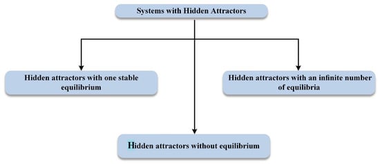
Figure 2.
The three main categories of systems with hidden attractors.
Therefore, in this work we study the application of [20] in such a system and extend the work of [30], by further analysing the dynamical behavior of the proposed chaotic system with line equilibrium, and considering additional simulations in the synchronization section. The results open up the potential of several future extensions.
The rest of this paper is organized in the following way. In Section 2, we present and analyze the proposed chaotic system. Section 3 gives a description of the problem of secure communication. The numerical results are reported in Section 4. Finally, Section 5 gives the conclusion and a discussion on future work.
2. The Proposed Dynamical System
2.1. System Description
We consider the following novel three-dimensional dynamical system
where a is the system parameter. System (1) has the following features:
- The system has only five terms. Till now only few chaotic 3D dynamical systems with five terms have been reported in literature. Most of them belong to the class of jerk systems and they have been introduced by Professor Sprott and his colleagues [47,48]. However, there are few others, which are written in the general 3D dynamical system’s form [49,50,51,52,53]. In 1997, Fu and Heidel rigorously proved that there can be no simpler system with a quadratic nonlinearity [54].
- It is a system without linear terms. Till now, there are only few chaotic 3D dynamical systems without linear terms, which have been reported in literature [55,56].
- By solvingIt is easy to verify that (1) has a line of equilibrium points . Therefore, system’s attractor is hidden.
- The amplitude is easily controllable.
- The system is symmetric through the transformation .This symmetry is observed in Figure 3, where two symmetric system’s periodic attractors, in the three different planes, for and initial conditions , with red color, and , with blue color, has been captured.
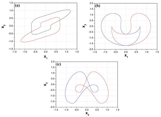 Figure 3. Symmetric system’s attractors in (a) plane, (b) plane, and (c) plane, for and initial conditions , with red color, and , with blue color.
Therefore, as far as the authors know, a 3D autonomous nonlinear dynamical system like this, which combines the aforementioned features and especially the first three of them, is the first of this kind.
2.2. Dynamical Analysis
In this section, we perform the analysis of system’s (1) dynamical behavior with initial conditions , by using well-known tools from the nonlinear theory, such as the bifurcation diagram, the continuation diagram, the spectrum of Lyapunov exponents and the phase portraits. In more details, in order to study the system dynamical behavior, we numerically integrate (1) using the fourth-order Runge-Kutta algorithm. For each set of parameter a and initial conditions used in this work, we select the time step to be equal to and the computations are carried out in extended precision mode. For every parameter settings, the system is integrated for a sufficiently long time and the transient is discarded. Furthermore, the system’s (1) Lyapunov exponents, for the selected set of initial conditions is calculated, by using the algorithm in [57].
Therefore, for revealing system’s (1) dynamics, regarding the value of parameter a, the system’s bifurcation diagram of versus the parameter a has been plotted (Figure 4a, blue colour). The bifurcation diagram is produced by plotting the variable when the trajectory cuts the plane with , as the control parameter a increases in tiny steps in the range . As illustrated in Figure 4a system (2) inserts to a chaotic region, which is interrupted by small periodic windows, through a period-doubling route, as the parameter a increases.
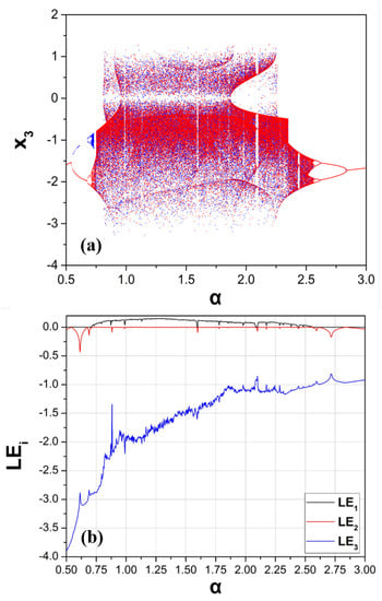
Figure 4.
(a) Bifurcation diagram (blue) (with same initial conditions in each iteration) and continuation diagram (red) (with different initial conditions in each iteration), and (b) Lyapunov Exponents (LE) of system (1) versus parameter a.
Next, the continuation diagram is obtained by plotting the variable when the trajectory cuts the plane with , as the control parameter, is increased in tiny steps in the same range of (Figure 4a, red colour). However, for this diagram the final state of the system, for a value of each control parameter, serves as the initial state for the system for the next value of the control parameter. This is the main difference between the continuation diagram and the bifurcation diagram. The comparison of the bifurcation diagram with the continuation diagram is a simple but effective way to find the ranges of values, in which a system develops coexisting attractors. In this way periodic and chaotic coexisting attractors for low values of the control parameter a are revealed. Figure 5 depicts the coexisting attractors for .
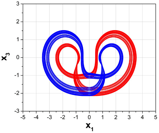
Figure 5.
Coexisting chaotic attractors in plane, for and initial conditions , with red color, and , with blue color.
Furthermore, the spectrum of Lyapunov exponents (LE) versus the parameter a is depicted in Figure 4b. From this diagram the system’s dynamical behavior, as it has been presented in Figure 4a, well coincides with the spectrum of the Lyapunov exponents. Consequently, as it is known from the nonlinear theory in periodic regions the system has only the maximum Lyapunov exponent equal to zero, while in chaotic regions the system has a positive maximum Lyapunov exponent.
Moreover, one may look at the plots of Figure 4a, and observe another interesting phenomenon. This phenomenon is called antimonotonicity and it has been introduced by Dawson et al. [58]. It is a fundamental phenomenon in the bifurcations theory [59,60,61], according to which periodic orbits are not only created but also destroyed, when one increases the control parameter smoothly in any neighborhood of a homoclinic tangency value, leading to reversals of period doubling cascades. So, antimonotonicity is due to tangential intersections between the stable and unstable manifolds of a system. According to the phenomenon of antimonotonicity, the system enters to chaos with the well-known period doubling route (period-1 → period-2 → … → chaos) and exits from the chaos following the reverse period doubling route (chaos → … → period-2 → period-1). This procedure has as a result the forming of a chaotic bubble in the bifurcation diagram.
In both diagrams of Figure 4a, the phenomenon of antimonotonicity is revealed. In more details, with the increase of the parameter a, a chaotic bubble of period-1 is generated, from 0.5 to 3 with step 0.002. Also, from Figure 4a chaos for a wide range of the parameter a is illustrated. In Figure 6 phase portraits for various values of the parameter a depict this behavior from period-1 to chaos and back to period-1 through the mechanism of period doubling. Figure 7 shows the 3D phase portrait for .
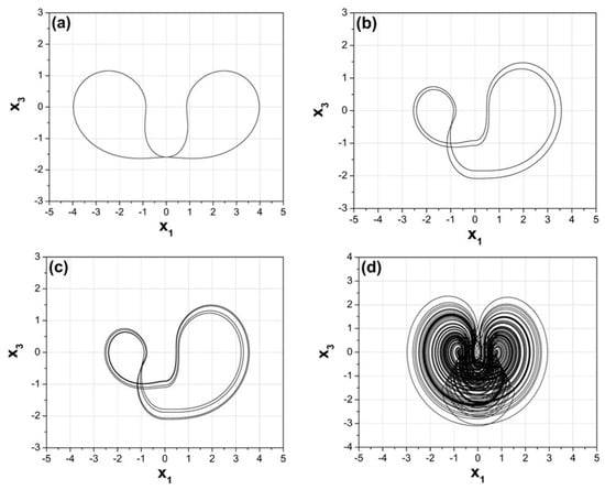
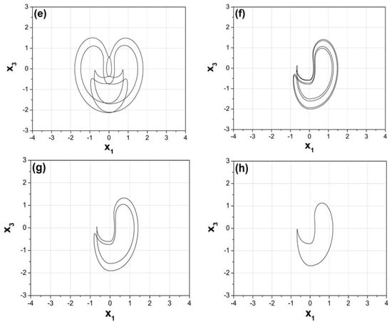
Figure 6.
Phase portraits in plane, for (a) (period-1), (b) (period-2), (c) (period-4), (d) (chaos), (e) (period-5), (f) (period-4), (g) (period-2), and (h) (period-1).
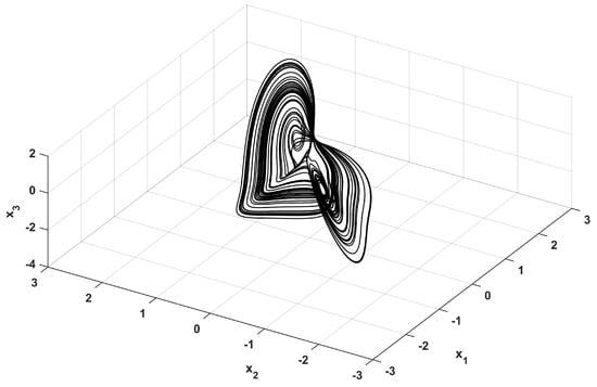
Figure 7.
3D Phase portrait for .
3. Realization of the System
In this section, we present an electronic circuit that emulates the proposed system (1). In that way, we demonstrate the system’s feasibility. From the viewpoint of practical applications [62,63] the hardware implementation of a mathematical chaotic model is an important issue, especially if the circuit is realized using commercially available components like amplifiers and integrated circuits [64,65,66].
The schematic of the circuit that emulates the system (1) is shown in Figure 8. This circuit consists of three integrators (), one inverting amplifier (), that are realized using the operational amplifier TL084, four signal multipliers () of type AD633, as well as two absolute value circuits.
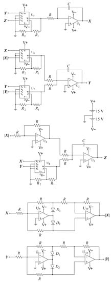
Figure 8.
Schematic of the circuit emulating system (1).
Using Kirchhoff’s circuit laws, we express the circuital equations of the designed circuit of Figure 8 as:
where the variables X, Y, and Z denote the voltages in the outputs of the integrators . We normalize the differential equations of system (3) using . One may notice that this system is equivalent to the system (1), with . We select the circuit components with the following values: , , , and , while the power supplies of all active devices are . The circuit of Figure 8 has been designed in Multisim and the Spice results are depicted in Figure 9, for parameter . In this way, the phase portraits of circuit’s behavior in various planes, for the same value of the parameter a, as in the corresponding phase portrait of Figure 6d, are depicted. As expected the obtained results from the Spice confirm the feasibility of the introduced system (1).
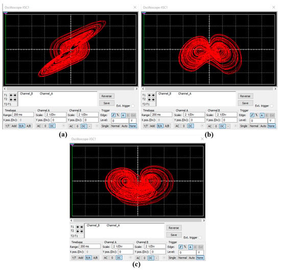
Figure 9.
Chaotic attractors produced from the circuit of Figure 8, for , in (a) plane, (b) plane and (c) plane.
4. Application to Secure Communications
In this section, we consider the application of the proposed system to the problem of secure communications. Now, the non-autonomous case of (1) is considered
where is the transmitted signal that is injected linearly in the system, the measurable output, are the transmitted signal coefficients and are matrices of appropriate dimensions. So here, the design assumes an input-state-output formulation.
To proceed with synchronization, and also successful estimation of the input signal, the transmitted signal is considered as an additional system state. This leads to the reformulation of the system as a rectangular descriptor system of the form
where
With this reformulation, by constructing an observer for the system (5), the augmented state can be estimated, and thus synchronization and input estimation can be simultaneously achieved, with the same precision. We make the following assumptions for the system:
- (A.1)
- , where n is the number of columns of E. So, by considering the form of E, one can see that this is equivalent to D having full column rank.
- (A.2)
- The nonlinear part satisfies the Lipschitz property, that is, there exists a positive scalar such that
Remark 1.
Assumption A.2 covers a wide range of chaotic systems. Even for systems that are not globally Lipschitz, a constant γ can be found so that the system satisfies the Lipschitz property locally, which can be useful for applications.
Under the above assumptions, the aim is to design an observer for system (5). The observer has the following form
where the matrices must be computed, so that the state approximates x, that is
In the same way as in [20,30,67], we apply the following steps for calculation of the observer matrices.
- Compute the matrix R, following the procedure given in ([67] Appendix A.)
- Compute the matrices , that correspond to the systemand check the solvability of the LMIfor and .
Remark 2.
In [68], the detectability condition
is shown to be necessary for the solvability of the LMI (9), where . To satisfy this, based on the structure of A, the addition of multiple outputs may be considered, to counter the absence of linear terms.
5. Simulation Results
For the simulation of the above observer design, we first consider the parameter values and , , and
The transmitted signal is . The initial conditions are taken as , , , , , , . The simulation results are shown in Figure 10. It is seen that the observer successfully estimates the states and input signal.
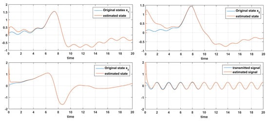
Figure 10.
Time response of states and signal and their estimations .
This design can also be used for the transmission of binary signals. Here we consider a binary information signal. The signal takes a random value of 1 or 0 every 0.2 s. The observer estimations are shown in Figure 11. The parameter values are , , and the output matrix is chosen as
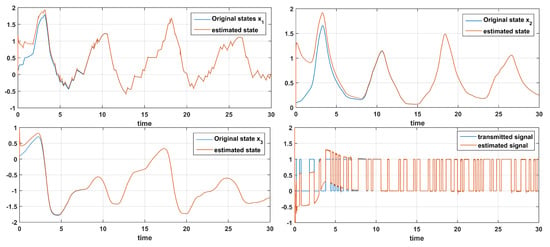
Figure 11.
Time response of states and signal and their estimations for a binary information signal.
As a further thought, Figure 12 depicts the transmission of two signals and , with , ,
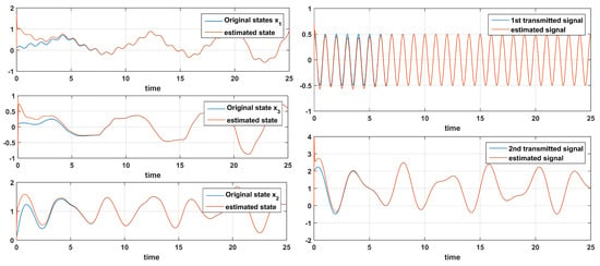
Figure 12.
Estimation of signals and .
6. Conclusions and Future Aspects
In the present work, a novel chaotic system with line equilibrium and one parameter was studied. First, a dynamical analysis was performed and it was shown that the system is chaotic for a range of parameter values. Then, the system was applied to the problem of secure communication. By considering the transmitted signal as an additional state, an observer was designed for a rectangular system to estimate the states and signal.
Subsequent studies of this work will consider more aspects for chaos based secure communication, utilizing systems with hidden attractors. These include systems of higher dimension, hyperchaotic systems [15,22], and discrete time systems [69,70]. Also, the transmission of different types of signals, for example for image transmission will also be considered, and also the nonlinear transmission of the information signal. Reduced order observers will be studied as well. The circuit implementation is also under study. It has been previously pointed that hardware limitations can arise, for example, in [15] it is noted that the resistance and capacitance of the circuit elements in the master and slave system will have slight deflections. Still, there is an interest in working on a design that will be robust in countering such limitations. Sensitivity analysis can be first studied numerically, considering minimal norm matrix perturbations. Also, the emergence of noise in the communication channel is a realistic implementation problem that should also be addressed.
Author Contributions
Conceptualization, C.V.; Formal analysis, C.V., V.-T.P., S.G., I.S.; Methodology, L.M., M.K.G., V.K.M.; Software, L.M., C.V.; Supervision, C.V., V.-T.P., S.G., I.S.; Validation, L.M., S.G., M.K.G., V.K.M.; Visualization, L.M., S.V.; Writing—original draft, L.M.; Writing—review & editing, C.V.
Funding
This research received no external funding.
Acknowledgments
The authors would like to thank the anonymous reviewers for their suggestions.
Conflicts of Interest
The authors declare no conflict of interest.
References
- Pecora, L.M.; Carroll, T.L. Synchronization in chaotic systems. Phys. Rev. Lett. 1990, 64, 821–824. [Google Scholar] [CrossRef] [PubMed]
- Volos, C.K.; Kyprianidis, I.M.; Stouboulos, I.N. Image encryption process based on chaotic synchronization phenomena. Signal Process. 2013, 93, 1328–1340. [Google Scholar] [CrossRef]
- Xu, Y.; Wang, H.; Li, Y.; Pei, B. Image encryption based on synchronization of fractional chaotic systems. Commun. Nonlinear Sci. Numer. Simul. 2014, 19, 3735–3744. [Google Scholar] [CrossRef]
- Tirandaz, H.; Karmi-Mollaee, A. Modified function projective feedback control for time-delay chaotic Liu system synchronization and its application to secure image transmission. Optik 2017, 147, 187–196. [Google Scholar] [CrossRef]
- Yang, T. A survey of chaotic secure communication systems. Int. J. Comput. Cogn. 2004, 2, 81–130. [Google Scholar]
- Martínez-Guerra, R.; García, J.J.M.; Prieto, S.M.D. Secure communications via synchronization of Liouvillian chaotic systems. J. Frankl. Inst. 2016, 353, 4384–4399. [Google Scholar] [CrossRef]
- Sambas, A.; Mamat, M.; Tacha, O. Design and numerical simulation of unidirectional chaotic synchronization and its application in secure communication system. J. Eng. Sci. Technol. Rev. 2013, 6, 66–73. [Google Scholar] [CrossRef]
- Akgul, A.; Calgan, H.; Koyuncu, I.; Pehlivan, I.; Istanbullu, A. Chaos-based engineering applications with a 3D chaotic system without equilibrium points. Nonlinear Dyn. 2016, 84, 481–495. [Google Scholar] [CrossRef]
- Wang, S.Y.; Zhao, J.F.; Li, X.F.; Zhang, L.T. Image blocking encryption algorithm based on laser chaos synchronization. J. Electr. Comput. Eng. 2016, 2016, 4138654. [Google Scholar] [CrossRef]
- Fischer, I.; Liu, Y.; Davis, P. Synchronization of chaotic semiconductor laser dynamics on subnanosecond time scales and its potential for chaos communication. Phys. Rev. A 2000, 62, 011801. [Google Scholar] [CrossRef]
- Kim, S.S.; Choi, H.H. Adaptive synchronization method for chaotic permanent magnet synchronous motor. Math. Comput. Simul. 2014, 101, 31–42. [Google Scholar] [CrossRef]
- Bae, Y.C.; Park, J.K. A study on obstacle avoid method and synchronization of multi chaotic robot for robot formation control based on chaotic theory. J. Korea Inst. Electron. Commun. Sci. 2010, 5, 534–540. [Google Scholar]
- Fallahi, K.; Leung, H. A cooperative mobile robot task assignment and coverage planning based on chaos synchronization. Int. J. Bifurc. Chaos 2010, 20, 161–176. [Google Scholar] [CrossRef]
- Volos, C.K. Motion direction control of a robot based on chaotic synchronization phenomena. J. Autom. Mob. Robot. Intell. Syst. 2013, 7, 64–69. [Google Scholar]
- Liao, T.L.; Huang, N.S. An observer-based approach for chaotic synchronization with applications to secure communications. IEEE Trans. Circuits Syst. I Fundam. Theory Appl. 1999, 46, 1144–1150. [Google Scholar] [CrossRef]
- Wang, H.; Han, Z.; Zhang, W.; Xie, Q. Chaotic synchronization and secure communication based on descriptor observer. Nonlinear Dyn. 2009, 57, 69. [Google Scholar] [CrossRef]
- Boutayeb, M.; Darouach, M.; Rafaralahy, H. Generalized state-space observers for chaotic synchronization and secure communication. IEEE Trans. Circuits Syst. I Fundam. Theory Appl. 2002, 49, 345–349. [Google Scholar] [CrossRef]
- Gupta, M.K.; Tomar, N.K.; Mishra, V.K.; Bhaumik, S. Observer Design for Semilinear Descriptor Systems with Applications to Chaos-Based Secure Communication. Int. J. Appl. Comput. Math. 2017, 3, 1313–1324. [Google Scholar] [CrossRef]
- Wang, H.; Zhu, X.J.; Gao, S.W.; Chen, Z.Y. Singular observer approach for chaotic synchronization and private communication. Commun. Nonlinear Sci. Numer. Simul. 2011, 16, 1517–1523. [Google Scholar] [CrossRef]
- Chandra, S.; Gupta, M.K.; Tomar, N.K. Synchronization of Rössler chaotic system for secure communication via descriptor observer design approach. In Proceedings of the 2015 International Conference on Signal Processing, Computing and Control (ISPCC), Himachal Pradesh, India, 24–26 September 2015; pp. 120–124. [Google Scholar]
- Lu, J.; Wu, X.; Lü, J. Synchronization of a unified chaotic system and the application in secure communication. Phys. Lett. A 2002, 305, 365–370. [Google Scholar] [CrossRef]
- Pham, V.T.; Volos, C.K.; Vaidyanathan, S.; Le, T.; Vu, V. A Memristor-Based Hyperchaotic System with Hidden Attractors: Dynamics, Synchronization and Circuital Emulating. J. Eng. Sci. Technol. Rev. 2015, 8. [Google Scholar] [CrossRef]
- Azar, A.T.; Volos, C.; Gerodimos, N.A.; Tombras, G.S.; Pham, V.T.; Radwan, A.G.; Vaidyanathan, S.; Ouannas, A.; Munoz-Pacheco, J.M. A novel chaotic system without equilibrium: Dynamics, synchronization, and circuit realization. Complexity 2017, 2017. [Google Scholar] [CrossRef]
- Cherrier, E.; Boutayeb, M.; Ragot, J. Observers-based synchronization and input recovery for a class of nonlinear chaotic models. IEEE Trans. Circuits Syst. I Regul. Pap. 2006, 53, 1977–1988. [Google Scholar] [CrossRef]
- Zaher, A.A.; Abu-Rezq, A. On the design of chaos-based secure communication systems. Commun. Nonlinear Sci. Numer. Simul. 2011, 16, 3721–3737. [Google Scholar] [CrossRef]
- Yang, J.; Zhu, F. Synchronization for chaotic systems and chaos-based secure communications via both reduced-order and step-by-step sliding mode observers. Commun. Nonlinear Sci. Numer. Simul. 2013, 18, 926–937. [Google Scholar] [CrossRef]
- Abdullah, A. Synchronization and secure communication of uncertain chaotic systems based on full-order and reduced-order output-affine observers. Appl. Math. Comput. 2013, 219, 10000–10011. [Google Scholar] [CrossRef]
- Yang, J.; Chen, Y.; Zhu, F. Singular reduced-order observer-based synchronization for uncertain chaotic systems subject to channel disturbance and chaos-based secure communication. Appl. Math. Comput. 2014, 229, 227–238. [Google Scholar] [CrossRef]
- Liao, T.L.; Tsai, S.H. Adaptive synchronization of chaotic systems and its application to secure communications. Chaos Solitons Fractals 2000, 11, 1387–1396. [Google Scholar] [CrossRef]
- Moysis, L.; Volos, C.; Pham, V.T.; Goudos, S.; Stouboulos, I.; Gupta, M.K. Synchronization of a Chaotic System with Line Equilibrium using a Descriptor Observer for Secure Communication. In Proceedings of the 2019 8th International Conference on Modern Circuits and Systems Technologies (MOCAST), Thessaloniki, Greece, 13–15 May 2019; pp. 1–4. [Google Scholar]
- Ha, Q.P.; Trinh, H. State and input simultaneous estimation for a class of nonlinear systems. Automatica 2004, 40, 1779–1785. [Google Scholar] [CrossRef]
- Chandra, S.; Gupta, M.K.; Tomar, N.K. Observer design approach to synchronize lorenz chaotic systems for secure communication. In Proceedings of the International Conference on Computational Modeling & Simulation, Colombo, Sri Lanka, 17–19 May 2017. [Google Scholar]
- Wang, X.; Chen, G. A chaotic system with only one stable equilibrium. Commun. Nonlinear Sci. Numer. Simul. 2012, 17, 1264–1272. [Google Scholar] [CrossRef]
- Molaie, M.; Jafari, S.; Sprott, J.C.; Golpayegani, S.M.R.H. Simple chaotic flows with one stable equilibrium. Int. J. Bifurc. Chaos 2013, 23, 1350188. [Google Scholar] [CrossRef]
- Jafari, S.; Sprott, J.; Golpayegani, S.M.R.H. Elementary quadratic chaotic flows with no equilibria. Phys. Lett. A 2013, 377, 699–702. [Google Scholar] [CrossRef]
- Wei, Z. Dynamical behaviors of a chaotic system with no equilibria. Phys. Lett. A 2011, 376, 102–108. [Google Scholar] [CrossRef]
- Wang, X.; Chen, G. Constructing a chaotic system with any number of equilibria. Nonlinear Dyn. 2013, 71, 429–436. [Google Scholar] [CrossRef]
- Jafari, S.; Sprott, J. Simple chaotic flows with a line equilibrium. Chaos Solitons Fractals 2013, 57, 79–84. [Google Scholar] [CrossRef]
- Jafari, S.; Sprott, J.C.; Molaie, M. A simple chaotic flow with a plane of equilibria. Int. J. Bifurc. Chaos 2016, 26, 1650098. [Google Scholar] [CrossRef]
- Chen, Y.; Yang, Q. A new Lorenz-type hyperchaotic system with a curve of equilibria. Math. Comput. Simul. 2015, 112, 40–55. [Google Scholar] [CrossRef]
- Gotthans, T.; Petržela, J. New class of chaotic systems with circular equilibrium. Nonlinear Dyn. 2015, 81, 1143–1149. [Google Scholar] [CrossRef]
- Gotthans, T.; Sprott, J.C.; Petrzela, J. Simple chaotic flow with circle and square equilibrium. Int. J. Bifurc. Chaos 2016, 26, 1650137. [Google Scholar] [CrossRef]
- Leonov, G.; Kuznetsov, N.; Mokaev, T. Hidden attractor and homoclinic orbit in Lorenz-like system describing convective fluid motion in rotating cavity. Commun. Nonlinear Sci. Numer. Simul. 2015, 28, 166–174. [Google Scholar] [CrossRef]
- Leonov, G.A.; Kuznetsov, N.V. Hidden attractors in dynamical systems. From hidden oscillations in Hilbert–Kolmogorov, Aizerman, and Kalman problems to hidden chaotic attractor in Chua circuits. Int. J. Bifurc. Chaos 2013, 23, 1330002. [Google Scholar] [CrossRef]
- Sharma, P.R.; Shrimali, M.D.; Prasad, A.; Kuznetsov, N.V.; Leonov, G.A. Controlling dynamics of hidden attractors. Int. J. Bifurc. Chaos 2015, 25, 1550061. [Google Scholar] [CrossRef]
- Pham, V.T.; Volos, C.; Jafari, S.; Wei, Z.; Wang, X. Constructing a novel no-equilibrium chaotic system. Int. J. Bifurc. Chaos 2014, 24, 1450073. [Google Scholar] [CrossRef]
- Sprott, J.C.; Linz, S.J. Algebraically simple chaotic flows. Int. J. Chaos Theory Appl. 2000, 5, 1–20. [Google Scholar]
- Sprott, J. Some simple chaotic jerk functions. Am. J. Phys. 1997, 65, 537–543. [Google Scholar] [CrossRef]
- Li, C.; Sprott, J. Chaotic flows with a single nonquadratic term. Phys. Lett. A 2014, 378, 178–183. [Google Scholar] [CrossRef]
- Munmuangsaen, B.; Srisuchinwong, B. A new five-term simple chaotic attractor. Phys. Lett. A 2009, 373, 4038–4043. [Google Scholar] [CrossRef]
- Sprott, J.C. Some simple chaotic flows. Phys. Rev. E 1994, 50, R647. [Google Scholar] [CrossRef]
- Yu, F.; Wang, C.; Wan, Q.; Hu, Y. Complete switched modified function projective synchronization of a five-term chaotic system with uncertain parameters and disturbances. Pramana 2013, 80, 223–235. [Google Scholar] [CrossRef]
- Malasoma, J.M. A new class of minimal chaotic flows. Phys. Lett. A 2002, 305, 52–58. [Google Scholar] [CrossRef]
- Fu, Z.; Heidel, J. Non-chaotic behaviour in three-dimensional quadratic systems. Nonlinearity 1997, 10, 1289. [Google Scholar] [CrossRef]
- Xu, Y.; Wang, Y. A new chaotic system without linear term and its impulsive synchronization. Optik 2014, 125, 2526–2530. [Google Scholar] [CrossRef]
- Mobayen, S.; Kingni, S.T.; Pham, V.T.; Nazarimehr, F.; Jafari, S. Analysis, synchronisation and circuit design of a new highly nonlinear chaotic system. Int. J. Syst. Sci. 2018, 49, 617–630. [Google Scholar] [CrossRef]
- Wolf, A.; Swift, J.B.; Swinney, H.L.; Vastano, J.A. Determining Lyapunov exponents from a time series. Phys. D Nonlinear Phenom. 1985, 16, 285–317. [Google Scholar] [CrossRef]
- Dawson, S.P.; Grebogi, C.; Yorke, J.A.; Kan, I.; Koçak, H. Antimonotonicity: Inevitable reversals of period-doubling cascades. Phys. Lett. A 1992, 162, 249–254. [Google Scholar] [CrossRef]
- Kan, I.; Yorke, J. Antimonotonicity: Concurrent creation and annihilation of periodic orbits. Bull. Am. Math. Soc. 1990, 23, 469–476. [Google Scholar] [CrossRef][Green Version]
- Kocarev, L.; Halle, K.; Eckert, K. Experimental observation of antimonotonicity in Chua’s circuit. Int. J. Bifurc. Chaos 1993, 3, 1051. [Google Scholar] [CrossRef]
- Kyprianidis, I.M.; Stouboulos, I.N.; Haralabidis, P.; Bountis, T. Antimonotonicity and chaotic dynamics in a fourth-order autonomous nonlinear electric circuit. Int. J. Bifurc. Chaos 2000, 10, 1903–1915. [Google Scholar] [CrossRef]
- Itoh, M. Synthesis of electronic circuits for simulating nonlinear dynamics. Int. J. Bifurc. Chaos 2001, 11, 605–653. [Google Scholar] [CrossRef]
- Petrzela, J.; Gotthans, T.; Guzan, M. Current-mode network structures dedicated for simulation of dynamical systems with plane continuum of equilibrium. J. Circuits, Syst. Comput. 2018, 27, 1830004. [Google Scholar] [CrossRef]
- Buscarino, A.; Fortuna, L.; Frasca, M.; Sciuto, G. A Concise Guide to Chaotic Electronic Circuits; Springer: New York, NY, USA, 2014. [Google Scholar]
- Elwakil, A.; Ozoguz, S. Chaos in pulse-excited resonator with self feedback. Electron. Lett. 2003, 39, 831–833. [Google Scholar] [CrossRef]
- Piper, J.R.; Sprott, J.C. Simple Autonomous Chaotic Circuits. IEEE Trans. Circuits Syst. II Express Briefs 2010, 57, 730–734. [Google Scholar] [CrossRef]
- Gupta, M.K.; Tomar, N.K.; Bhaumik, S. Full-and reduced-order observer design for rectangular descriptor systems with unknown inputs. J. Frankl. Inst. 2015, 352, 1250–1264. [Google Scholar] [CrossRef]
- Gupta, M.; Tomar, N.; Bhaumik, S. Observer design for descriptor systems with Lipschitz nonlinearities: An LMI approach. Nonlinear Dynam. Syst. Theory 2014, 14, 292–302. [Google Scholar]
- Lu, J.-G.; Xi, Y.-G. Chaos communication based on synchronization of discrete-time chaotic systems. Chin. Phys. 2005, 14, 274. [Google Scholar]
- Zhang, W.; Su, H.; Zhu, F.; Yue, D. A note on observers for discrete-time Lipschitz nonlinear systems. IEEE Trans. Circuits Syst. II Express Briefs 2012, 59, 123–127. [Google Scholar] [CrossRef]
© 2019 by the authors. Licensee MDPI, Basel, Switzerland. This article is an open access article distributed under the terms and conditions of the Creative Commons Attribution (CC BY) license (http://creativecommons.org/licenses/by/4.0/).