Article

An Improved Calculation Model for the Prediction of the Wear of Coated Electrical Contacts

Precision Engineering Laboratory, Ostwestfalen-Lippe University of Applied Sciences and Arts, 32657 Lemgo, Germany
*
Author to whom correspondence should be addressed.
Technologies 2019, 7(4), 77; https://doi.org/10.3390/technologies7040077
Submission received: 28 August 2019 / Revised: 20 October 2019 / Accepted: 27 October 2019 / Published: 31 October 2019
(This article belongs to the Special Issue Microswitching Technologies)

Abstract

:
To connect terminals in a cyber–physical system, large quantities of electrical contacts are used. In order to guarantee a high reliability of the system, the lifetime of the electrical contacts should be very long. Thus, it is of great importance to understand the failure mechanism and then to predict the lifetime of the electrical contacts. For the applications under high thermal and/or mechanical loads, noble plating is a good choice, considering its inertness to oxidation. For noble plating, one of the most critical failure mechanisms is the fretting wear. Wear debris generated in the contact area, acting as the third bodies, will greatly influence the further wear behavior and electrical performance. In this study, the state of the art regarding third bodies is firstly reviewed, and then the influence of the third bodies on the wear and electrical performance is investigated, from the aspects of lifetime and the element distributions in contact area. Finally, an example of prediction of the wear of noble plating is shown with the consideration of the third bodies. Based on this study, by involving the third bodies, the wear of noble plating can be predicted with a higher accuracy.

1. Introduction

In recent decades, the development of cyber–physical systems has gained a great boost, which stimulates the demand of high-quality electrical contacts. The electrical contacts are the critical components for the transmission of the current and signals between the devices in the cyber–physical systems. Even if one electrical contact fails, it may lead to the shutdown of a function or even the whole system. Therefore, it is of great importance to prolong the lifetime of the electrical contacts. Generally, in order to improve the performance of the electrical contacts, plating is used on the base materials. The plating can be briefly divided into two groups, namely non-noble and noble plating. For the applications under high thermal and/or mechanical loads, the noble plating is a good choice, because the noble materials are inert to oxygen and they have a very high corrosion resistance. However, the electrical contacts can experience the micro motions, which result from the vibration or the different thermal expansion coefficients of the holding materials attached to the contacts. When the temperature increases, the holding materials will expand differently, making the electrical contacts to move different distance from their original positions. When the temperature varies, cyclic micro motions will be generated. Due to these micro motions the noble plating will suffer fretting wear. The wear debris can be aggregated in the contact area and change the surface condition greatly. As a consequence, the wear behavior and the electrical performance will be changed. Therefore, understanding the formation and the distribution of the wear debris and its influence on the wear properties can help to predict the wear process and the lifetime of the noble plating on electrical contacts.
The designed lifetime of the systems is usually very long, for example over 15 years or for autonomous vehicles over 300,000 km mileages. The electrical contacts are expected to serve for this duration. However, it is impossible to conduct such a long-term test considering its unaffordable time-consumption as well as the high cost. For this reason, a methodology to predict the wear on the noble plating should be established. Then, with this methodology, the wear of the contacts after long-term operation can be predicted with the data from the short-term test under the operating condition. Since after a long-term application, the surface is worn and the wear debris is generated and aggregated in the contact area, the effect of the third bodies on the wear behavior of the plating should be analyzed and considered, in order to accomplish a precise prediction.
Many mechanisms can produce wear debris, as shown in Figure 1 [1]. The wear debris can be generated within different physical mechanisms, depending on materials and the sliding conditions. In general, the wear debris is detached from the surface by micro stresses due to the force and relative motion. The possible mechanisms may work individually or jointly to produce the wear debris [1]:
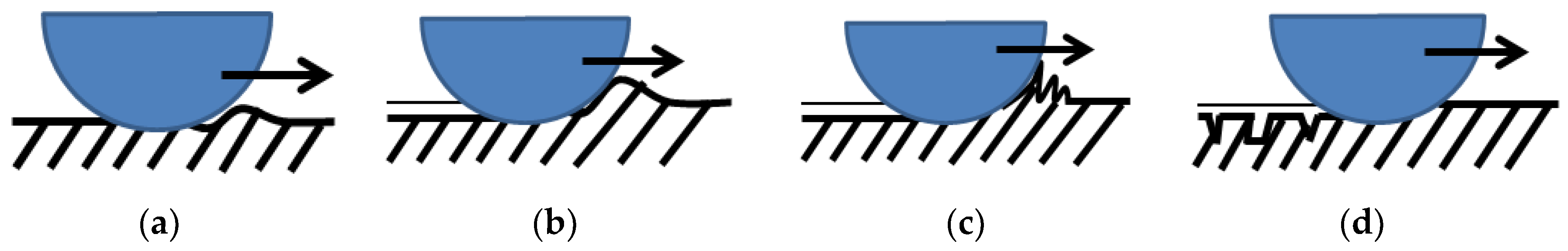
  • Micro deformation: the surface is plastically deformed in the form of grooves and scratches.
  • Micro ploughing: the surface is plowed by hard particles due to such as the oxides of metal wear debris or the contaminants from the environment.
  • Micro cutting: the adhesive junctions are broken down between the surfaces thereby resulting in mechanical failure of the contacting asperities.
  • Micro cracking: the nucleation and propagation of the surface cracks and voids generate the particles between the surfaces.
Although a lot of work has been conducted to investigate the wear debris, it is still difficult to clearly identify and understand the third-body behavior, since it requires direct observations of the state of the particles and the contact area during the wear process. However, most of the wear observations are conducted post factum, which means that the wear process should be disrupted, and then the samples should be disassembled for analysis. During this process, the distribution of wear particles and the state of the contact area can be changed. Thus, the way to characterize and reflect the presence of wear debris should be carefully selected. It is found that besides the traditional way of measuring the weight loss or wear depth after the tests, the coefficient of friction can be a good indicator to interpret the state of contact area as well as the wear debris. The condition of the wear debris is reflected by the coefficient of friction [2]. Stability in the coefficient of friction reveals that the amount of the debris in the contact area is constant [1].
The morphology of the wear debris can be different, for example flakes, chips, thin plates etc. For the contacts experiencing oscillating motions, the wear debris of flake and chip forms can be aggregated and rolled into cylindrical, spherical and needle-like particles, due to the opposite tangential forces at the top and bottom surfaces of the particles. These kinds of forms can act as “solid lubricants” so that the coefficient of friction is reduced [1,3,4,5] (Figure 2) resulting in the wear reduction [1].
Hintikka et al. have also found that the loose wear particles in the contact area can protect against the wear of quenched and tempered steel specimens. If the wear particles are periodically removed from the interface, the fretting wear will significantly increase [6]. For the application of wheel–rail contact, the presence of the “natural” third bodies can help to limit the wear and fatigue of the surface [7].
In investigation conducted by the research group of Fouvry, the energy dissipation is used to quantify the wear in oscillating sliding contacts. The frictional force is integrated to calculate the accumulated friction work dissipated through the interface and compared with the wear volume for the metallic surface [8]. When the electrical contacts endure the reciprocating sliding, the wear debris can remain in the interface to form a thick third-body layer. The coefficient of friction can be reduced and the friction energy dissipation causing the wear of the surface also decreases. Thus, the wear rate decreases [9]. When applied in the numerical simulation, with the consideration of the formation of the third bodies, the simulated results agree better with the measured results [10].
Apart from the investigation from Fouvry’s group, the energy based approach is also used by other researchers. In [11], the intensity of the wear can be related to the friction work according to Fleischer [12], and by merging to Archard’s equation [13], the wear coefficient is positively correlated to the coefficient of friction. Foko Foko et al. also use the energy based calculation to simulate the wear of a seal ring [14]. Hence, we have used the coefficient of friction as an indicator for the change of the wear coefficient in this study.
In this study, two arrangements of the electrical contacts are used to generate different third-body distribution. The lifetime of the arrangements is determined. Based on this, the critical sample arrangement is found. The element content in the contact area of the critical arrangement is measured. Then a methodology to calculate the thickness reduction of the critical arrangement is established with the consideration of the influence of the third bodies. Finally, the model is verified with the experimental results.

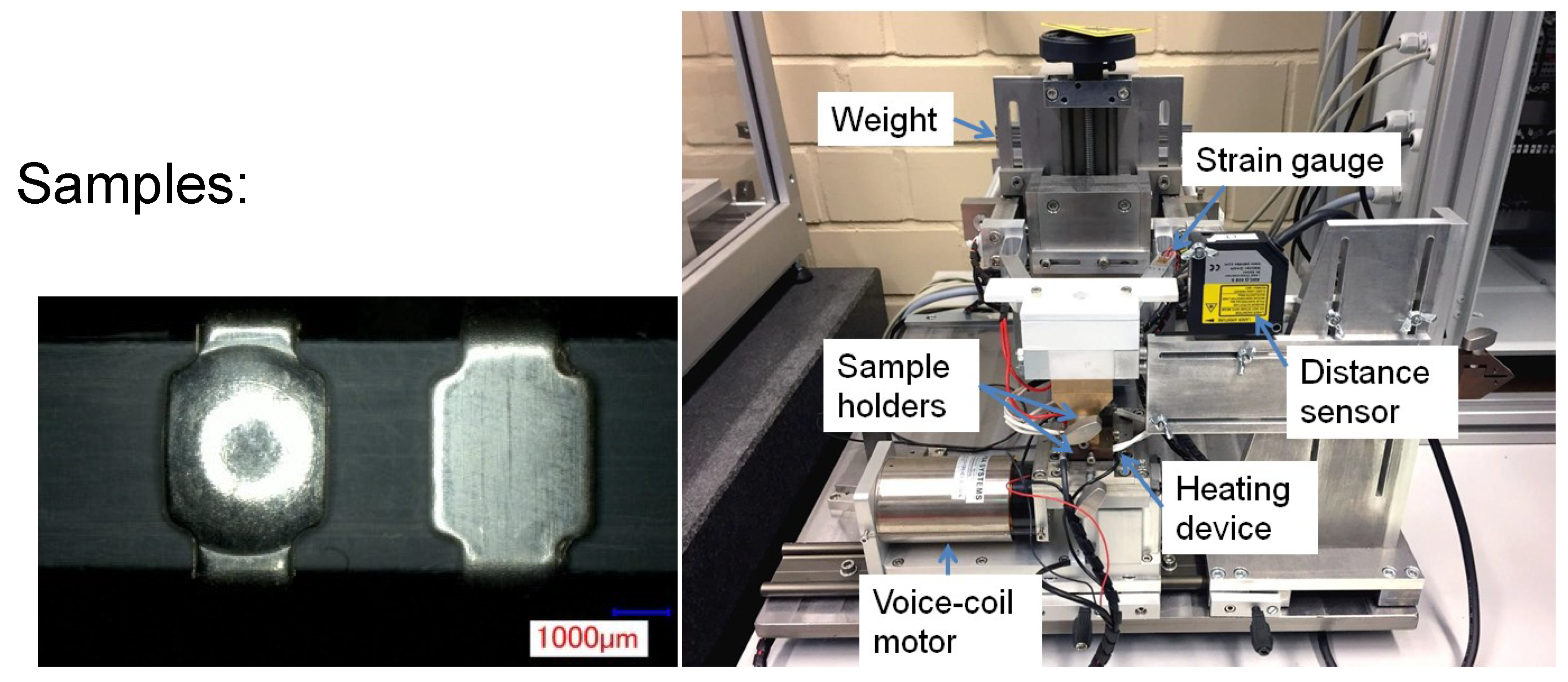
2. Materials and Methods

The base material of the samples was bronze (CuSn4). It was firstly cut to the flat parts and then half of them are deformed to the spherical parts. The radius at the contact point was 4.5 mm. The base materials were degreased in a degreasing bath. Silver plating was used as an example of the noble plating. The contacts were electroplated with silver to the nominal thickness of 6 µm, which was confirmed by an X-ray fluorescence device (XRF, Fischerscope® X-Ray system XDAL, from Helmut Fischer GmbH + Co.KG, Sindelfingen, Germany).
The wear property of the silver plated electrical contacts was analyzed by the wear and fretting corrosion test. The test device was developed in our laboratory and shown in Figure 3. The test parameters are listed in Table 1. During the test, the normal force, frictional force, coefficient of friction and contact resistance are recorded. The contact resistance was measured by the “four-point-method”. Two sample arrangements were used, namely “sphere on plane” and “plane on sphere”. The “sphere on plane” arrangement means that the sphere part was clamped to the upper sample holder and the plane part was clamped to the lower sample holder; the “plane on sphere” arrangement consisted of the plane part to the upper sample holder and the sphere part to the lower sample holder. Two test strategies were employed. One of the strategies was to terminate the wear and fretting corrosion test at a predefined cycle, and then the thickness reduction at this cycle can be indicated by the difference between the initial coating thickness and the remaining coating thickness after the wear and fretting corrosion test. The coating thickness was measured by XRF. The XRF measurements were conducted on the sphere and the plane separately for every sample. The data from the distance sensor only acted as reference, and they were not used for the quantitative characterization, since the remaining wear debris in the contact area distorted the results of the measurement. The other was to run the test until the contact resistance reached 300 mΩ. The corresponding fretting cycle was recorded as the lifetime of the sample in the wear and fretting corrosion test. Based on these tests, the critical arrangement is then identified. After the test, the element content of the samples with the critical arrangement was measured by the energy-dispersive X-ray spectroscopy (EDS, Bruker XFlash® Detector 4010, Ettlingen, Germany) with a scanning electron microscope (SEM, Zeiss EVO 50 VP, Germany). The distribution of the wear debris was observed by the digital microscope (digital microscope VHX-2000 by Keyence Corporation, Osaka, Japan).
The wear prediction is conducted for the samples with the critical arrangement. The fundament for the wear prediction is based on Archard’s wear equation as Equation (1) [15]:
V w e a r = k · F · s ,
where Vwear is the volumetric wear, k is the specific wear coefficient, F is the normal force and s is the sliding distance. The sliding distance is calculated by Equation (2):
s = 2 · N · s 0 ,
where N is the fretting cycles, and s0 is the fretting amplitude from peak to peak.
In order to predict the wear process of the silver plating more precisely, many aspects should be considered. It is found that the wear curve consists of different phases, Figure 4. Phases I and II were investigated in this study, since the wear through often happens during these phases. In each phase, the dominant factor for the thickness reduction is different. The spherical parts were the focus, since they had larger thickness reduction compared to the plane parts [16].
For the prediction of the wear curve, a methodology with following steps is established:
  • Calculation of the deformation after the contact of the two contact parts considering the surface roughness with assistance of finite element analysis (FEA), involving the elastic-plastic material behavior and the surface roughness. The geometry is drawn corresponding to the real samples. The roughness is defined on the flat part according to the roughness measured with a confocal microscope μsurf explorer from Nanofocus AG, Germany. According to [16], the roughness structure for the tested samples can be simplified as triangular prisms. The boundary conditions are set based on the condition in the test.
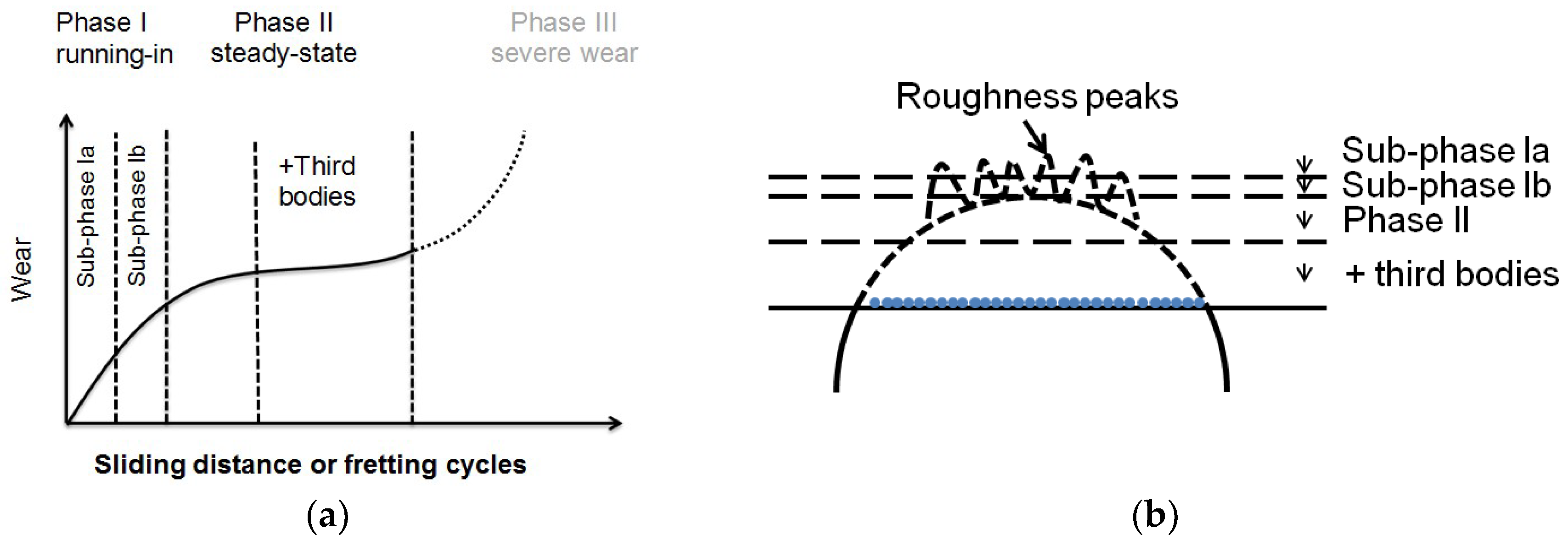
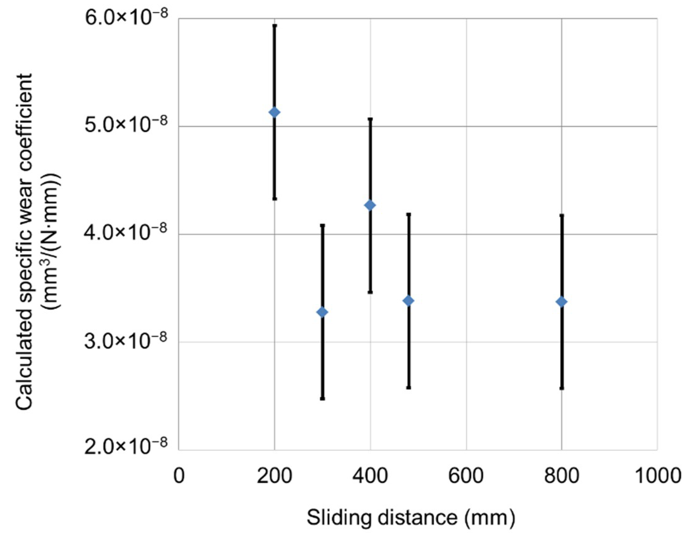
  • Calculation of specific wear coefficient using data in phase I. For this purpose, more wear and fretting corrosion tests are conducted with the critical arrangement for different predefined fretting cycles in the running-in phase. The thickness reduction is measured after the tests. According to [16], the specific wear coefficient kcal, using the data in Phase I and considering the topography of the surface and its change due to the plastic deformation, can be calculated as following:
    k c a l = R s m 6 R k · s 1 · F i = 1 m ( D 0 , i h 0 , i · h 1 3 + 3 D 0 , i · h 1 2 + 3 D 0 , i · h 0 , i · h 1 ) ,
    where h1 is the wear depth in Phase I based on an assumption that every triangular prism experiences the same wear depth in the wear process, m is the number of triangular prisms involved in contact area, s1 is the sliding distance in Phase I, Rsm is the measured average groove width, Rk is the measured core roughness depth, h0,i is the reduction of coating thickness parallel to the normal force simulated by FEA, D0,i is the length of the deformed triangular prism simulated by FEA.
  • Modification of the calculated specific wear coefficient according to the topography: simplification of the roughness on the flat part α s i m p l i f i c a t i o n   and the gaps on the roughness ribs α g a p following Equation (4):
    k m o d i ,   P h a s e   I = α s i m p l i f i c a t i o n · α g a p · k c a l ,
    where, according to [16], αsimplification and αgap are 0.5 and 0.9, respectively.
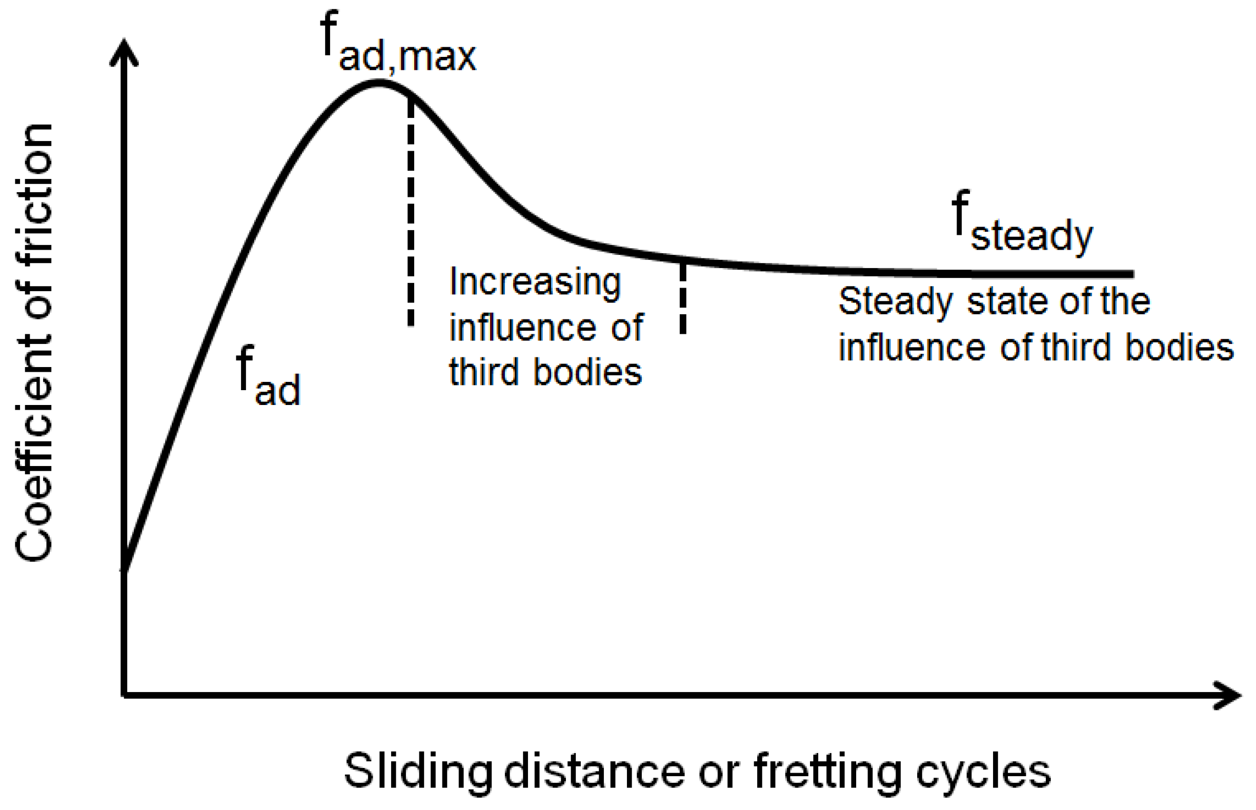
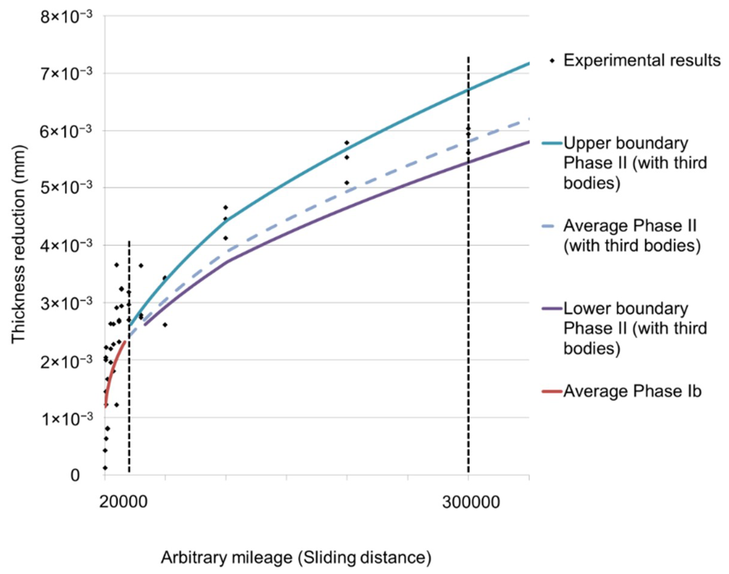
  • Involving the influence of the third bodies after a long-term sliding:
A steady coefficient of friction indicates a stable amount of wear debris in the contact area [1]. Thus, the influence of wear debris is characterized by the change of the friction during the sliding as shown in Figure 2 following Equation (5):
α t h i r d b o d y = f s t e a d y , l f a d , m a x ,
where the fsteady,l is the friction of coefficient at the lth steady period, since we notice that more than one steady coefficient of friction can exist and fad,max is the maximum value of the coefficient of adhesive friction. The αthird-body considers the reduced friction energy dissipation which in turn decreases the wear rate.
This coefficient is further multiplied to the kcal to modify the specific wear coefficient in phase II:
k m o d i ,   P h a s e   I I , l = α s i m p l i f a c t i o n · α g a p · α t h i r d b o d y · k c a l
  • Prediction of the wear curve:
The correlation between the sliding distance and the wear depth in phase I can be determined according to [15]:
s 1 = 1 k m o d i , P h a s e   I   · ( 1674 · h 1 3 + 3.3 · h 1 2 + 0.0026 · h 1 ) ,
where s1 is the sliding distance in phase I, h1 is the wear in phase I.
The correlation between the sliding distance and the wear depth in phase II during the first steady state of coefficient of friction is according to [15]:
s 2 , 1 = π k m o d i , P h a s e   I I , 1 · F [ 1 3 h 2 , 1 3 + ( R R k ) h 2 , 1 2 + ( 2 R R k R k 2 ) h 2 , 1 ] ,
where s2,1 and h2,1 are the sliding distance and the wear in phase II during the first steady state of coefficient of friction, respectively, and R is the radius of the spherical part.
For the lth steady period of coefficient of friction (l ≥ 2), the correlation between the sliding distance and the wear depth is:
s 2 , l = π k m o d i , P h a s e   I I , l · F [ 1 3 h 2 , l 3 + ( R R 2 , l 1 ) h 2 , l 2 + ( 2 R R 2 , l 1 R 2 , l 1 2 ) h 2 , l ] ,
where s2,l and h2,l are the sliding distance and the wear in phase II during the lth steady state of coefficient of friction, respectively, R2,l−1 is the total thickness reduction at the end of the (l − 1)-th steady coefficient of friction in phase II, which can be calculated by:
R 2 , l 1 = h 0 + h 1 , e n d + 1 n = l 1 h 2 , n ,
where h2,n is the wear at the end of the (l − 1)-th steady state of coefficient of friction in phase II, h0 is the thickness reduction due to deformation after the contact of two contact parts, h1,end is the wear at the end of phase I.
Total sliding distance in phases I and II is:
s t o t = s 1 , e n d + 1 l s 2 , l ,
where stot is the total sliding distance in phases I and II, s1,end is the sliding distance at the end of phase I.
Total thickness reduction is:
h t o t = h 0 + h 1 , e n d + 1 l h 2 , l
where htot is the total thickness reduction in phases I and II.

3. Results

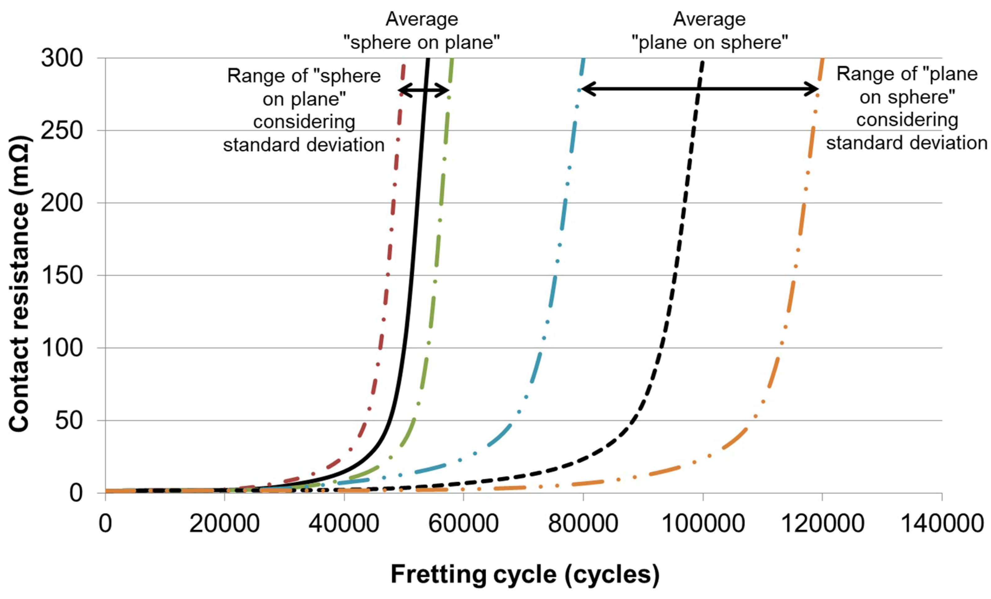
3.1. Lifetime of Electrical Contacts Tested with Different Sample Arrangements

The development of the contact resistance is schematically illustrated in Figure 5. The lifetime of the samples tested with different sample arrangements is listed in Table 2. The “sphere on plane” arrangement was the critical one. Since both of the arrangements were used in the most applications, the critical arrangement “sphere on plane” was used for the further investigation.

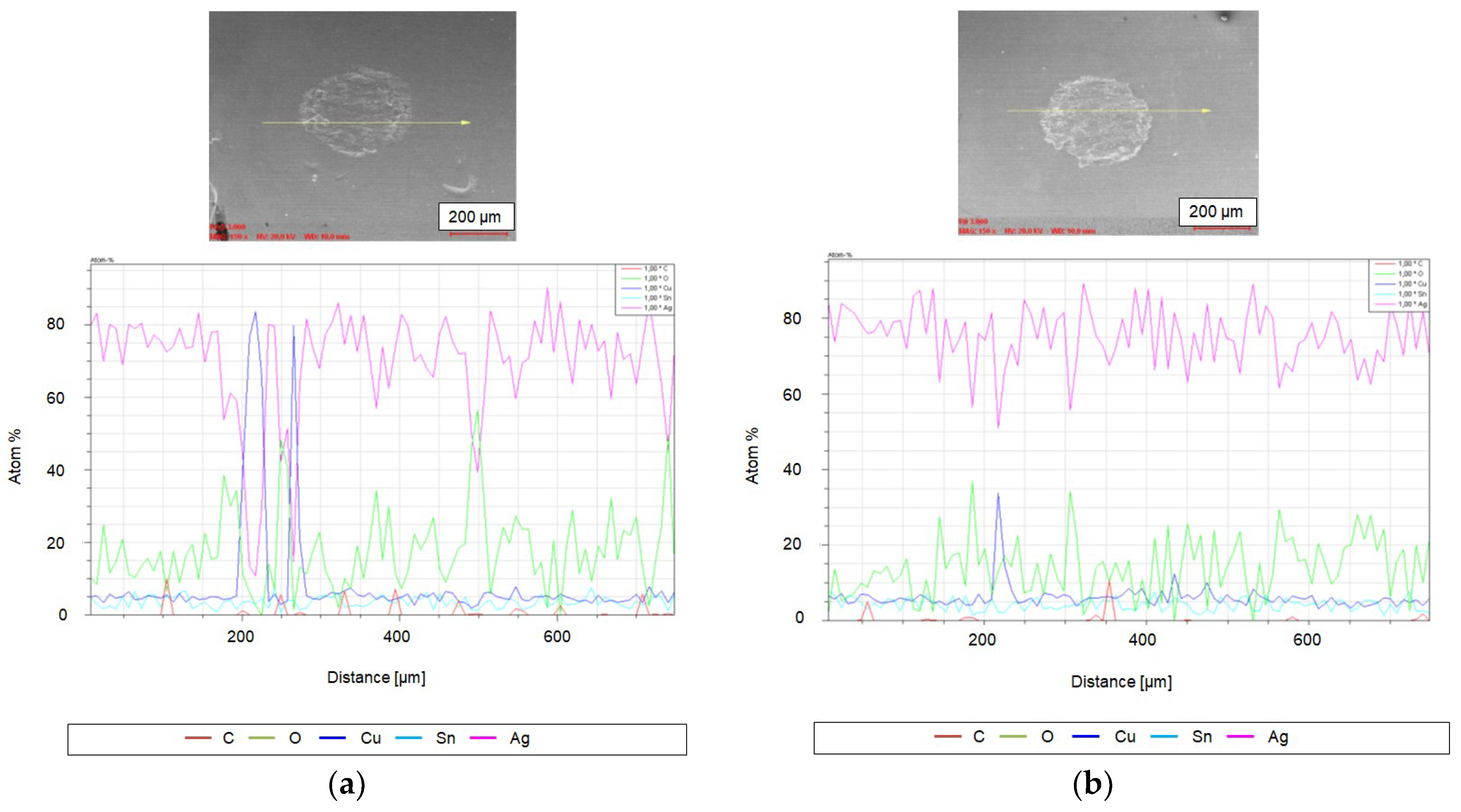
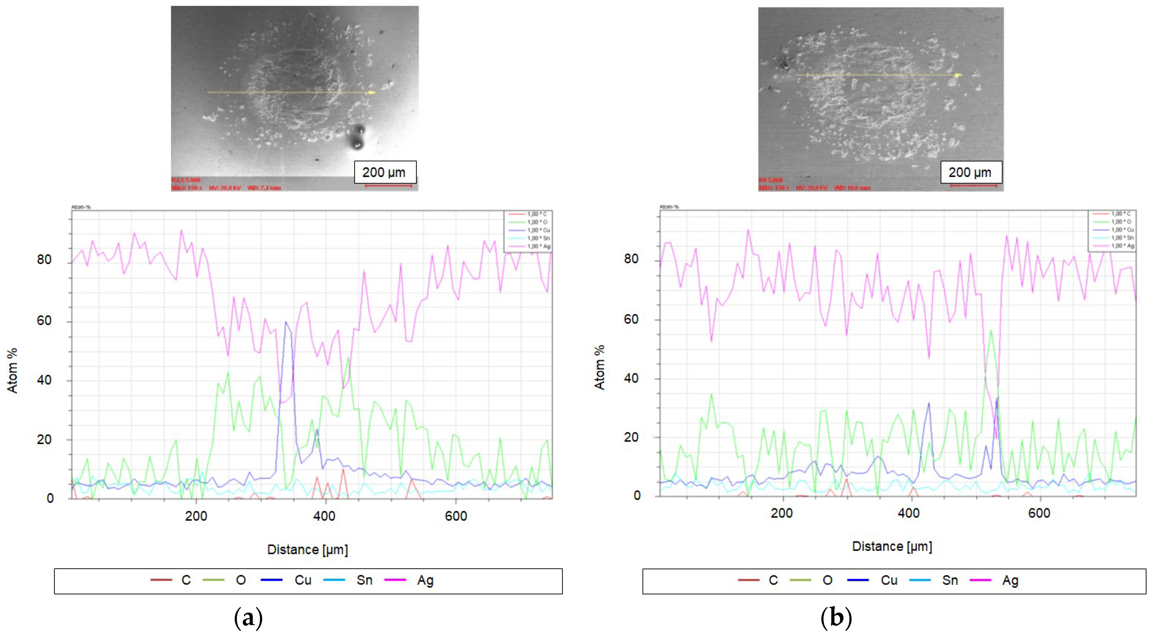
3.2. Element Content in Contact Area of Samples with Critical Sample Arrangement

The element distribution in the contact area of the samples after 3000 and 5000 fretting cycles with the “sphere on plane” arrangement is tested with EDS in SEM, shown in Figure 6 and Figure 7. The sphere part endures more severe wear than the plane part, indicated by the larger decrease in the silver content in contact area [17]. After 3000 fretting cycles, only very little local wear-through took place on the sphere part, due to the surface roughness and unevenness of the silver plating. After 5000 fretting cycles, the silver plating is worn, but the silver element is still the dominant element in the contact area with the content mostly over 50 at.%.

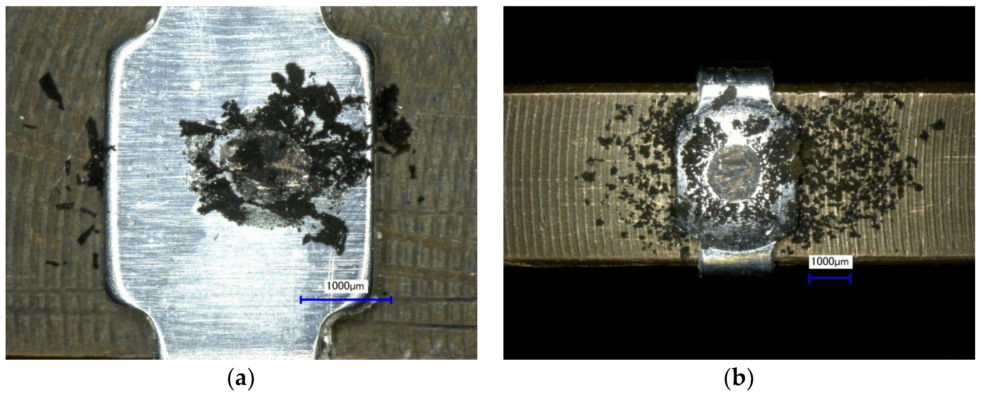
3.3. Distribution of Wear Debris after the Wear and Fretting Corrosion Test

The distribution of the wear debris after the electrical failure in the wear and fretting corrosion test is shown in Figure 8. With regard to the “plane on sphere” sample arrangement, the third bodies are more easily removed from the contact area, compared to the “sphere on plane” sample arrangement. Thus, wear debris distributes in a large range outside the contact area. Third bodies influence the wear coefficient in different ways. From the point of view of the friction energy, the wear coefficient decreases with the decreasing coefficient of friction. On the other hand, since the partial wear through took place after several thousand fretting cycles, the oxides of the wear debris from the base material can occur in the contact area. Then the third bodies consist of different composition, the silver, the base material and the oxides. The oxides were harder than the silver plating, and thus they can increase the wear. Moreover, after the wear-through of the silver plating, third bodies consisted of more oxides of the wear debris from base material, and this intensified the wear on the base material, producing more wear debris that can be further oxidized in turn. If the oxides cannot be removed from the contact area, they will be aggregated, blocking the current path, and thus causing the electrical failure. Since the removal of the third bodies was more difficult in the sample arrangement “sphere on plane”, it took less time to aggregate the oxides causing the electrical failure for this arrangement. Consequently, the lifetime of the “sphere on plane” is shorter, and this arrangement is the critical one. Therefore, the investigation is focused on the critical sample arrangement “sphere on plane”.

3.4. Thickness Reduction of the Samples with Critical Arrangement

Since the degradation of silver plating on the sphere is more severe according to the EDS results in Section 3.2, the investigation is focused on the wear on the sphere parts. The thickness reduction on the spherical parts along with the sliding distance is shown in Figure 9. The phase I is identified with the rapid increase in the thickness reduction, and then in phase II, the thickness reduction increases slowly.

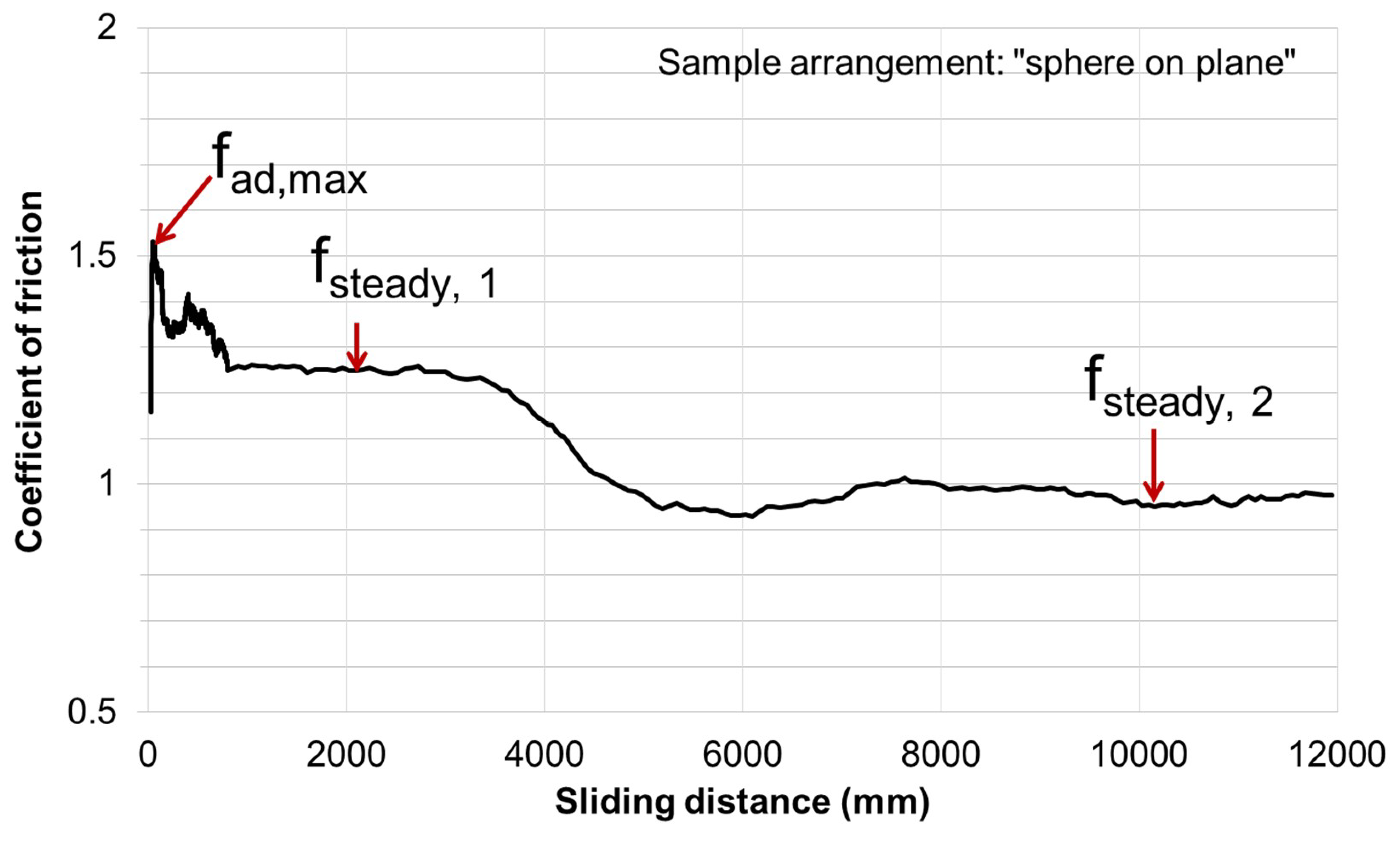
3.5. Coefficient of Friction of Samples with Critical Arrangement

A typical development of the coefficient of friction of the “sphere on plane” arrangement is shown in Figure 10. The maximum coefficient of friction fad,max, and the steady coefficients of friction fsteady,1 and fsteady,2 are pointed out in Figure 10. Therefore, the influence of the third bodies was calculated in Table 3.

4. Discussion

4.1. Calculation and Modification of Specific Wear Coefficient

According to Equation (3), the specific wear coefficient is calculated as shown in Figure 11. The points with the sliding distance from 200 mm to 800 mm are used for calculation. Below this range, the thickness reduction is very close to the deformation simulated in FEA, so it is dominated by the deformation of roughness peaks. Above this range, the wear can develop to phase II, and Equation (3) is invalid. The kcal calculated at each sliding distance is in a range from 3.3 × 10⁻⁸ mm3/(N∙mm) to 5.1 × 10⁻⁸ mm3/(N∙mm). The mean value of kcal at all sliding distances is 3.9 × 10⁻⁸ mm3/(N∙mm). The standard deviation is 8 × 10⁻⁹ mm3/(N∙mm).
According to Equations (4)–(6), the specific wear coefficient can be modified as listed in Table 4.

4.2. Wear Curves

According to Equations (7)–(12), the wear curve can be calculated and illustrated as Figure 12. The deviation between the average predicted value and the measured value is −0.9% after the long-term operation, which is greatly improved compared to the deviation of 16% from the prediction without consideration of third bodies and −3.6% from the prediction with the consideration of third bodies only by the last steady coefficient of friction in [15].
The wear of the contacts after a long-term operation can be predicted based on the wear data collected from a short period test under the operating condition. For instance, for the automobile, the contacts in the vehicles experiencing different mileages during the test driving are disassembled to measure the wear and then the wear at a high mileage can be extrapolated according to the methodology established in the study, with the assumption of the average thermal and/or mechanical loads on the electrical contacts in the operation in each mileage being the same.

5. Conclusions

In this paper, the influence of third bodies on friction and wear was firstly reviewed. Two sample arrangements, namely “sphere on plane” and “plane on sphere”, are used to generate different distribution of third bodies, and then the “sphere on plane” is found to be the critical arrangement. Third bodies influence the wear coefficient in different ways. From the point of view of the friction energy, the wear coefficient decreases with the decreasing coefficient of friction. On the other hand, with the occurrence of the partial wear through, which will take place after several thousand cycles of micro motion, the base material begins to oxidize. The oxides are harder than the silver plating and they in turn can increase the wear coefficient. In the case of “sphere on plane”, more oxide debris will remain in the contact area, which makes the “sphere on plane” the critical arrangement. A methodology is developed to predict the wear process with regard to this arrangement. The influence of the third bodies is taken into consideration, and different steady coefficient of friction is referred to. The predicted wear curve is validated by the experimental results. A good agreement between the predicted value and the measured value after the long-term operation is obtain. The deviation is −0.9%. The prediction precision is greatly improved, compared to the prediction without consideration of the third bodies or only with the consideration of third bodies by the last steady coefficient of friction. Based on this study, it is possible to predict the wear of the electrical contacts with noble plating after long-term operation with the data from the short-term test under the operating condition.

Author Contributions

H.Y. conducted the simulation, experiments, analysis, established the methodology, validated the calculation model and wrote the original draft; J.S. initialized the investigation and the methodology, conducted the supervision and reviewed the paper.

Funding

This study is partly financed by the German Federal Ministry for Economic Affairs and Energy (BMWi, IGF, 20139 N).

Conflicts of Interest

The authors declare no conflict of interest.

References

  1. Zmitrowicz, A. Wear debris: a review of properties and constitutive models. J. Theor. Appl. Mech. 2005, 43, 3–35. [Google Scholar]
  2. Suh, N.P.; Sin, H.-C. On the genesis of friction and its effect on wear. In Solid Contact and Lubrication; Cheng, H.S., Keer, L.M., Eds.; American Society of Mechanical Engineers: New York, NY, USA, 1980; Volume 39, pp. 167–183. [Google Scholar]
  3. Song, J.; Schinow, V. Correlation between friction and wear properties and electrical performance of silver coated electrical connectors. Wear 2015, 330–331, 400–405. [Google Scholar] [CrossRef]
  4. Zum Gahr, K.H. Abrasiver Verschleiß metallischer Werkstoffe; VDI-Verlag: Düsseldorf, Germany, 1981. [Google Scholar]
  5. Zanoria, E.S.; Danyluk, S.; Mcnallan, M.J. Formation of cylindrical sliding-wear debris on silicon in humid conditions and elevated temperatures. Tribol. Trans. 1995, 38, 721–727. [Google Scholar] [CrossRef]
  6. Hintikka, J.; Lehtovaara, A.; Mäntylä, A. Third particle ejection effects on wear with quenched and tempered steel fretting contact. Tribol. Trans. 2016, 60, 70–78. [Google Scholar] [CrossRef]
  7. Niccolini, E.; Berthier, Y. Wheel–rail adhesion: laboratory study of “natural” third body role on locomotives wheels and rails. Wear 2005, 258, 1172–1178. [Google Scholar] [CrossRef]
  8. Fouvry, S.; Liskiewicz, T.; Kapsa, Ph.; Hannel, S.; Sauger, E. An energy description of wear mechanisms and its applications to oscillating sliding contacts. Wear 2003, 255, 287–298. [Google Scholar] [CrossRef] [Green Version]
  9. Fouvry, S.; Laporte, J.; Perrinet, O.; Jedrzejczyk, P.; Graton, O.; Alquier, O.; Sautel, J. Fretting Wear of Low Current Electrical Contacts: Quantification of Electrical Endurance. In Proceedings of the 63rd IEEE Holm Conference on Electrical Contacts, Denver, CO, USA, 10–13 September 2017; pp. 1–11. [Google Scholar] [CrossRef]
  10. Arnaud, P.; Fouvry, S.; Garcin, S. A numerical simulation of fretting wear profile taking account of the evolution of third body layer. Wear 2017, 376–377, 1475–1488. [Google Scholar] [CrossRef]
  11. Terwey, J.T.; Poll, G. Energy based modelling of adhesive wear in the mixed lubrication regime. In Proceedings of the 60th German Tribology Conference 2019 (60. Tribologie-Fachtagung 2019), Göttingen, Germany, 23–25 September 2018. Presentation No. 61. [Google Scholar]
  12. Fleischer, G.; Wolmirstedt, H.G.; Thum, H. Verschleiß und Zuverlässigkeit; VEB Verlag Technik: Berlin, Germany, 1980. [Google Scholar]
  13. Archard, J.F. Contact and Rubbing of Flat Surfaces. J. Appl. Phys. 1953, 24, 981–988. [Google Scholar] [CrossRef]
  14. Foko Foko, F.; Heimes, J.; Magyar, B.; Sauer, B. Reibenergiebasierte Verschleißsimulation für Radialwellendichtringe. In Proceedings of the 60th German Tribology Conference 2019 (60. Tribologie-Fachtagung 2019), Göttingen, Germany, 23–25 September 2018. Presentation No. 47. [Google Scholar]
  15. Yuan, H.; Song, J.; Schinow, V. A Modification of the Calculation Model for the Prediction of the Wear of Silver-Coated Electrical Contacts with Consideration of Third Bodies. In Proceedings of the 64th IEEE Holm Conference on Electrical Contacts, Albuquerque, NM, USA, 14–18 October 2018; pp. 310–316. [Google Scholar] [CrossRef]
  16. Yuan, H.; Song, J.; Schinow, V. Simulation methodology for prediction of the wear on silver-coated electrical contacts with a sphere/flat configuration. IEEE Trans. Compon. Packag. Manuf. Technol. 2018, 8, 364–374. [Google Scholar] [CrossRef]
  17. Song, J.; Schinow, V.; Yuan, H. Third bodies in electrical contacts — Wear and electrical performance. In Proceedings of the 63rd IEEE Holm Conference on Electrical Contacts, Denver, CO, USA, 10–13 September 2017; pp. 117–124. [Google Scholar] [CrossRef]
Figure 1. Wear micro-mechanisms to produce wear debris: (a) micro deformation; (b) micro ploughing; (c) micro cutting; (d) micro cracking [1].
Technologies 07 00077 g001
Figure 2. Development of coefficient of friction in a wear process, fad: the coefficient of adhesive friction; fad,max: maximum value of fad; fsteady: the steady coefficient of friction.
Technologies 07 00077 g002
Figure 3. Wear and fretting corrosion test device and samples.
Technologies 07 00077 g003
Figure 4. Wear process and the dominant factor in each phase, schematically: (a) Different phases in a wear process; (b) dominant factor causing thickness reduction in each phase: deformation of the roughness peaks in Sub-phase Ia; wear off of the roughness peaks in sub-phase Ib; contact surface is smoothed when the wear process moves to phase II, and the wear occurs on the spherical segment approximately for the spherical part; after long-term operation, the third bodies are aggregated in the contact area and influence the wear greatly.
Technologies 07 00077 g004
Figure 5. Development of contact resistance during tests.
Technologies 07 00077 g005
Figure 6. Scanning electron microscope (SEM) images of the wear scars and energy-dispersive X-ray spectroscopy (EDS) in X-ray Linescans mode across the contact area after 3000 fretting cycles: (a) on the sphere; (b) on the plane.
Technologies 07 00077 g006
Figure 7. SEM images of the wear scars and EDS in X-ray Linescans mode across the contact area after 5000 fretting cycles: (a) on the sphere; (b) on the plane.
Technologies 07 00077 g007
Figure 8. Distribution of the wear debris of different sample arrangement: (a) on the plane part after 6.2 × 10⁴ fretting cycles, arrangement “sphere on plane”; (b) on the sphere part after 1.3 × 10⁵ fretting cycles, arrangement “plane on sphere”.
Technologies 07 00077 g008
Figure 9. Thickness reduction of the spherical parts with “sphere on plane” arrangement.
Technologies 07 00077 g009
Figure 10. Typical development of the coefficient of friction.
Technologies 07 00077 g010
Figure 11. Calculated specific wear coefficient and the standard deviation.
Technologies 07 00077 g011
Figure 12. Prediction of wear curve with the consideration of the third bodies in different stages.
Technologies 07 00077 g012
Table 1. Test parameters.
ParameterValue
Amplitude peak-peak200 µm
Normal force3 N
Temperatureambient temperature (20 °C~23 °C)
Fretting frequency1 Hz
Relative humidity35~45%
Table 2. Lifetime of the electrical contacts with different arrangements.
Arrangement
Sphere on PlanePlane on Sphere
Lifetime (cycles)5.4 × 1041.3 × 105
5.1 × 1045.9 × 104
5.0 × 1041.0 × 105
5.5 × 1041.0 × 105
5.2 × 1041.2 × 105
6.2 × 1049.8 × 104
Average lifetime (cycles)5.4 × 1041.0 × 105
Standard deviation (cycles)4 × 1032 × 104
Table 3. Coefficient of friction and the influence of the third bodies.
fad,maxfsteady,1αthird-body,1Average αthird-body,1fsteady,2αthird-body,2Average αthird-body,2
1.51.250.830.810.950.630.64
1.71.350.791.10.65
1.61.300.811.00.62
Table 4. Modified specific wear coefficient.
k m o d i , P h a s e   I [ mm 3 / ( N · mm ) ] k m o d i , P h a s e   I I , 1 [ mm 3 / ( N · mm ) ] k m o d i , P h a s e   I I , 2 [ mm 3 / ( N · mm ) ]
Maximum2.3 × 10−81.9 × 10−81.5 × 10−8
Minimum1.5 × 10−81.2 × 10−89.4 × 10−9
Average1.8 × 10−81.4 × 10−81.1 × 10−8

