Article

Microstructure and Corrosion Resistance of Sn-3Ag-0.5Cu-xBi Solders

by
Michaela Halmanová
1,
Ivona Černičková
1,
Patrícia Danišovičová
1,
Patrik Šulhánek
1,
Marián Drienovský
1,
Xabier Zubizarreta Cuerda
2,
Róbert Havlík
1,
Libor Ďuriška
1 and
Marián Palcut
1,*
1
Faculty of Materials Science and Technology in Trnava, Slovak University of Technology in Bratislava, Ulica Jána Bottu 25, 917 24 Trnava, Slovakia
2
Bilbao School of Engineering, University of the Basque Country, Barrio Sarriena s/n, 48940 Leioa, Spain
*
Author to whom correspondence should be addressed.
Technologies 2026, 14(8), 509; https://doi.org/10.3390/technologies14080509
Submission received: 14 July 2026 / Revised: 9 August 2026 / Accepted: 13 August 2026 / Published: 17 August 2026
(This article belongs to the Section Innovations in Materials Science and Materials Processing)

Abstract

Sn-3Ag-0.5Cu-xBi alloys (SAC305-xBi) represent promising lead-free alternatives for low-temperature soldering. Low Bi concentrations can strengthen SAC-based solders through solid-solution strengthening, refining β–Sn grains and transforming needle-like Ag3Sn phases into equiaxed morphologies. However, excessive Bi alloying may induce precipitation of brittle Bi particles, cause microstructural instability and interfacial degradation, thereby weakening the solder joint performance. As such, the concentration of Bi in the SAC305 alloys should be carefully controlled. In this work, the microstructure and corrosion behavior of Sn-3Ag-0.5Cu-xBi solder alloys (SAC305-xBi, where x = 0, 1, 2 and 4 wt. %) were investigated. Attention has been paid to the influence of low Bi concentration on the microstructure, morphology, and chemical composition of the phases present in the solder alloys before and after corrosion exposure. The alloys were prepared by induction melting of Sn, Ag, Cu and Bi lumps under Ar gas. The microstructure of the SAC305 and SAC305-1Bi alloys represented a hypoeutectic microstructure with dendritic (Sn) grains and the ternary eutectic, consisting of (Sn), Cu6Sn5 and Ag3Sn, located in inter-dendritic regions. In the SAC305-2Bi and SAC305-4Bi alloys, a segregation of (Bi) particles was observed in addition to dendritic (Sn) and ternary eutectic. The (Bi) particles were located at the (Sn)Ag3Sn interface in the inter-dendritic spaces of the (Sn) solid solution. The corrosion resistance of the as-cast alloys was studied in aqueous NaCl electrolyte (3.5 wt. %) using electrochemical methods. Open circuit potentials of the alloys were found to increase with increasing concentration of Bi. The highest corrosion current was found for the SAC305-1Bi alloy. It was observed that micro-galvanic cells at the Sn-Ag3Sn interface were the initiating factors of corrosion in the SAC305-1Bi alloy. The corrosion activity of the SAC305-1Bi alloy is related to the high density of fine Ag3Sn particles. The higher fraction of Ag3Sn particles provided a dense network of local galvanic interaction sites, leading to the acceleration of the corrosion rate. The presence of discrete Bi precipitates in the SAC305-2Bi and SAC305-4Bi alloys, on the other hand, partially reduced the risk of galvanic corrosion. Since Bi has a higher standard electrode potential compared to Sn, the Bi/Ag3Sn and Bi/Cu6Sn5 couples were less prone to corrosion. The corrosion mechanism of the SAC305-xBi alloys is discussed, and results are compared to previously studied SAC-Bi alloys.

1. Introduction

Tin–lead (Sn–Pb) solder alloys have been used for decades due to their favorable soldering characteristics, reliability, and low manufacturing cost. However, due to the toxicity of lead, the European Union’s RoHS directive has prohibited Sn–Pb solders in consumer electronics in European markets [1]. This regulatory shift has led to the development of alternative lead–free Sn-based solder alloys designed to maintain good wettability, appropriate melting temperatures, mechanical integrity, and controlled interfacial intermetallic compound (IMC) formation. Among these, Sn–Cu, Sn–Ag, and Sn–Ag–Cu (SAC) systems have emerged as the most promising alternatives, offering a balance of mechanical properties, interfacial reliability, and environmental compatibility [2,3]. Due to these properties, SAC-based solders are widely considered for applications in commercial, automotive, and power electronics, where solder joints must provide both mechanical integrity and long-term reliability under service conditions [4].
The most widely used SAC-based solder is SAC305. It consists of 96.5 wt. % Sn, 3 wt. % Ag, and 0.5 wt. % Cu. The silver content improves wettability, thermal fatigue resistance, and mechanical stress tolerance, while copper stabilizes intermetallic phases such as Cu6Sn5, thereby enhancing the overall joint reliability. The microstructure of the SAC305 alloy comprises a β–Sn matrix with dispersed Ag3Sn and Cu6Sn5 intermetallics, which improve yield strength, tensile strength, and hardness [3,5]. The mechanical response of SAC305 is sensitive to temperature and strain rate, with reported tensile strengths around 32 MPa [4]. Despite the above-given favorable properties, SAC alloys exhibit certain limitations, including relatively high melting points, suboptimal wettability, and coarse microstructures. SAC305 exhibits a solidus temperature of approximately 217 °C [6]. As such, it is higher than the melting point of eutectic Sn–Pb [7,8]. To overcome these challenges and further improve the reliability of solder joints, alloying additions such as Bi, Ni, Sb, Ga, and nanoparticles have been investigated [3,4,9]. Bismuth has been shown to be particularly effective at improving properties of SAC solders. Low Bi concentrations (≤1 wt. %) strengthen SAC-based solders through solid-solution strengthening, refining β–Sn grains, and transforming needle-like Ag3Sn phases into equiaxed morphologies, which enhances creep resistance and reduces crack initiation. Bi also moderates the growth of interfacial IMCs, producing thinner, more planar layers that improve interfacial bonding and mechanical durability [4,10]. At higher Bi concentrations (≥2 wt. %), Bi-rich precipitates form, increasing brittleness and reducing mechanical performance. Optimal Bi content (≈0.5–1.5 wt. %) provides a balance between strength, ductility, and thermal fatigue resistance, refining grains, homogenizing the eutectic structure, and suppressing excessive IMC growth, which in turn improves creep and fatigue life under cyclic loading [11].
In addition to thermal and mechanical reliability, corrosion resistance is an important factor affecting the long-term performance of lead-free solder joints, particularly in humid and chloride-containing environments. Corrosion processes may promote the formation of surface oxides, localized attack, and micro-galvanic interactions between the β–Sn matrix and intermetallic phases, thereby accelerating degradation of the solder joint [5,12,13,14,15]. Under practical service conditions, electronic assemblies may be exposed to high relative humidity, condensation, chloride-containing dust, airborne salts, and ionic residues originating from soldering, handling, or cleaning processes [16]. In the presence of moisture, these contaminants may form a thin conductive electrolyte layer on the surface of the assembly, promoting localized corrosion, leakage currents, and electrochemical migration between adjacent conductors [17]. These degradation mechanisms are particularly relevant to automotive, outdoor, industrial, marine, and power-electronic applications exposed to fluctuating temperature, humidity, and contamination conditions.
Since Bi affects both the β–Sn matrix and the morphology of intermetallic phases, it can also influence electrochemical heterogeneity and, consequently, the corrosion behavior of SAC-based solders [4,8,18]. Bi lowers the melting point and enhances the wettability of SAC305, facilitating better solder spreading on copper substrates and promoting uniform interfacial bonding [7,8]. These combined effects expand the process window during reflow soldering and contribute to long-term joint reliability. However, the beneficial effects of Bi are limited by its solubility in Sn; exceeding the solubility limit leads to precipitation of Bi-rich phases, reducing ductility and introducing microstructural heterogeneities that may negatively impact both mechanical and corrosion performance. Consequently, careful optimization of Bi concentration is essential to achieve a synergistic improvement of mechanical, thermal, and electrochemical properties in high-reliability SAC-based solder joints [4].
Bi can also improve the corrosion resistance [19,20]. At low concentrations (0.5–1 wt. %), Bi regulates the growth rate of Cu6Sn5 layers during thermal aging, preventing abnormal thickening of brittle interfacial IMCs and reducing the formation of cracks and voids that act as diffusion paths for corrosive species. However, excessive Bi (>2 wt. %) may segregate along grain boundaries or form coarse Bi-rich particles, which can increase local electrochemical heterogeneity and promote micro-galvanic corrosion [21]. Electrochemical studies in chloride-containing solutions have indicated that moderate Bi additions may improve corrosion resistance, whereas excessive Bi can accelerate localized corrosion due to particle aggregation and increased microstructural heterogeneity [4,22,23]. However, the published results do not indicate a straightforward effect of Bi on corrosion resistance. The observed response depends on the Bi concentration, the base-alloy composition, the distribution of Bi between the Sn-rich matrix and Bi-rich precipitates, the morphology of the intermetallic phases, and the corrosive environment. Tamási et al. reported that Bi- and Ag-containing multicomponent solders exhibited lower corrosion resistance than SAC305 in 3.5 wt. % NaCl solution [22]. However, since their alloys also differed in their Ag, Cu, Sb, and Ni contents, the individual contribution of Bi could not be isolated. Medgyes et al. investigated SAC0307–1Bi–xMn and SAC305 alloys in NaCl solution and showed that corrosion and electrochemical migration behavior depended on the combined alloy composition and resulting microstructure [23]. As the Bi concentration was fixed in the modified alloys, this study did not determine the concentration-dependent influence of Bi in an otherwise unchanged SAC305 system.
A more direct comparison was provided by Luo et al., who investigated SAC305 alloys containing 0, 2, 4, 4.5, and 5 wt. % Bi in 3.5 wt. % NaCl while maintaining the original Ag and Cu contents [19]. They reported a non-monotonic effect of Bi content on the corrosion resistance of SAC305–xBi alloys, with improved corrosion performance at intermediate Bi concentrations and deterioration at 5 wt. % Bi. The deterioration observed at 5 wt. % Bi was associated with pronounced accumulation of Bi at grain boundaries, whereas lower additions resulted in a finer distribution of Bi-containing particles. Wang et al. reported the highest corrosion resistance at an intermediate Bi concentration in SAC305–0.1Ni–2.0Sb–xBi alloys [24]. However, the simultaneous presence of Ni and Sb prevents the observed behavior from being attributed exclusively to Bi. These findings indicate that the corrosion response of Bi-containing SAC solders is strongly dependent on alloy composition, phase constitution, and microstructural distribution.
Studies of other Bi-containing Sn-based solder systems can provide additional insight into the mechanisms controlling corrosion. In binary Sn–Bi alloys, the corrosion behavior was governed by phase constitution and galvanic interactions between Sn-rich and Bi-rich constituents, with preferential dissolution of the less noble Sn-rich constituent [25]. In Sn–3Zn–xBi alloys, the addition of 1 wt. % Bi increased corrosion susceptibility, whereas higher Bi additions reduce corrosion resistance because of changes in the amount and distribution of Bi-rich particles [26]. Lu et al. demonstrated that the type and concentration of ionic contamination significantly influence the electrochemical migration behavior of Sn–58Bi solder [27]. A recent comparative study showed marked differences in corrosion resistance and electrochemical migration behavior among Sn–58Bi, Sn–37Pb, Sn–0.7Cu, and SAC305 solder alloys [28]. Jung and Lee further showed that multicomponent Sn–Ag–Bi–Cu–Ni solders may exhibit different corrosion responses depending on their chemical and phase constitution and the distribution of microstructural constituents [29]. Although these alloy systems differ from SAC305–xBi, their studies demonstrate that corrosion behavior cannot be predicted solely from the nominal Bi concentration.
As mentioned above, the available literature contains unresolved and partly conflicting conclusions concerning the influence of Bi on the corrosion behavior of SAC-based solders. Direct comparison among previous studies is complicated because several investigations simultaneously varied the contents of Ag, Ni, Sb, Mn, Zn, or other alloying elements. For example, Erer investigated Sn–(3-x)Ag–0.5Cu–xBi alloys containing 0, 0.5, 1, and 2 wt. % Bi in 1 M HCl solution [30]. However, Bi was introduced by replacing Ag, and the resulting corrosion behavior therefore reflected both increasing Bi content and decreasing Ag content. Conversely, Luo et al. maintained the original Ag and Cu contents of SAC305 but did not investigate a 1 wt. % Bi composition [19]. Thus, the corrosion behavior of SAC305–1Bi, representing a low-Bi composition without a pronounced population of discrete Bi-rich precipitates, remains insufficiently understood.
The aim of this study is to investigate the corrosion behavior of unmodified SAC305 solder and SAC305 alloys containing 1, 2, and 4 wt. % Bi in 3.5 wt. % NaCl solution. Attention is paid to the influence of low Bi concentration on the microstructure, morphology, and chemical composition of the phases present in the solder alloys before and after corrosion exposure. We also aim to study the relationship between Bi concentration, microstructure, and the morphology and chemical composition of the corrosion products formed on the alloys. The goal of the study is to identify the phase(s) preferentially attacked during corrosion and to determine which microstructural constituents exhibit higher corrosion resistance in the investigated environment. The additions of 1, 2, and 4 wt. % Bi represent microstructurally relevant concentration levels while maintaining constant Ag and Cu contents. The 1 wt. % Bi addition represents a low-Bi composition in which the effect of Bi predominantly associated with the Sn-rich matrix can be evaluated. The 2 wt. % Bi addition represents an intermediate concentration and enables comparison with previously published studies conducted in NaCl and HCl environments. The 4 wt. % addition represents a composition with a more pronounced presence of Bi-rich precipitates and allows comparison with the corrosion results of Luo et al. [19] and the precipitation observations of Belyakov et al. [31]. The selected concentration series thus allows the corrosion behavior of a low-Bi alloy without pronounced Bi-rich precipitation to be compared with alloys containing distinct Bi-rich particles.

2. Materials and Methods

The SAC305-xBi alloys (x = 0, 1, 2, 4 wt. %) were prepared by induction melting of high-purity Sn, Ag, Cu and Bi granules (99.99 wt. %, Camex, Měšice, Czech Republic). The granules were weighed in their respective concentrations and placed inside cylindrical aluminum oxide crucibles. The total mass of each sample was 50 g. The crucibles were positioned in a vacuum induction furnace equipped with water-cooled coils. The chamber was evacuated to approximately 5 Pa and subsequently purged with high-purity argon to ensure an inert atmosphere and complete displacement of residual O2. Once the inert atmosphere was established, the furnace was heated above the melting points of the constituent metals to achieve a fully liquid state. The molten alloy was stirred and kept in a liquid state for 10 min. to ensure a complete distribution of the elements. After homogenization, the alloy was allowed to solidify under argon, preventing oxidation during cooling. The solidified alloys retained the form of cylindrical ingots (approximately 30 mm diameter and 10 mm thickness).
After being cooled, the samples were carefully removed from the furnace, then from the crucibles and further metallographically prepared. The preparation consisted of wet grinding with SiC papers (successive grades 600, 800, 1200 and 2500), followed by polishing with diamond suspensions down to 1 μm surface roughness. The Buehler Automet 300 polisher (Buehler Ltd., Lake Bluff, IL, USA) was used for the procedure.
The corrosion behavior of the SAC–Bi alloys was evaluated in a 3.5 wt. % NaCl aqueous solution. The electrolyte was prepared by dissolving 35 g of NaCl in demineralized water and diluting the solution to a total mass of 1 kg. The electrolyte was prepared immediately prior to the experiment. The electrolyte was not de-aerated to simulate real conditions that the solders may experience during their exposure to saline solutions. Each corrosion experiment was carried out in a three-electrode glass cell controlled by potentiostat PGU 10 V-1A-IMP-S (Jaissle Electronic Ltd., Waiblingen, Germany). The corrosion cell volume was 0.5 L, and the experiments were carried out at laboratory temperature (22 °C). The three electrodes were the working electrode, counter electrode and reference electrode. The working electrode was a polished surface of the SAC305-xBi alloy. The surface area that was exposed to the electrolyte was 537 mm2. The counter electrode was a Pt sheet (400 mm2). The reference electrode was a Ag/AgCl electrode immersed in saturated KCl solution. After positioning the electrodes, the corrosion cell was placed inside a Faraday cage. The electrodes were connected to a potentiostat using isolated cables. Open circuit potentials (OCPs) of the SAC305-xBi alloys were measured for 30 min during their exposure in the 3.5 wt. % NaCl electrolyte. After the OCP stabilization, potentiodynamic measurements were conducted to obtain a current-potential response in the SAC305-xBi alloys. The experiments were carried out in linear sweep voltammetry mode using a 1 mV/s scan rate. The polarization started at potentials 500 mV lower than the stabilized OCP values and continued in the positive direction to record both the cathodic and anodic responses. The resulting potentiodynamic curves were analyzed using Tafel analysis. Each corrosion experiment was run in triplicate to check for reproducibility. The electrochemical parameters are provided as averages.
The microstructures of the as-prepared and as-corroded SAC305-xBi alloys were examined using a JSM-7600F Field Emission Gun scanning electron microscope (SEM/JEOL, Akishima, Tokyo, Japan). The accelerating voltage of the electron beam was 20 kV. The backscatter electron imaging mode (BSE) was applied to obtain information on the microstructure and chemical composition of the individual microstructure constituents. An energy-dispersive X-ray spectroscopy analyzer (EDS/Oxford Instruments, Abingdon, UK) was used to obtain quantitative information on the chemical composition of individual microstructure constituents. The EDS was operated by INCA software (version 5.04).
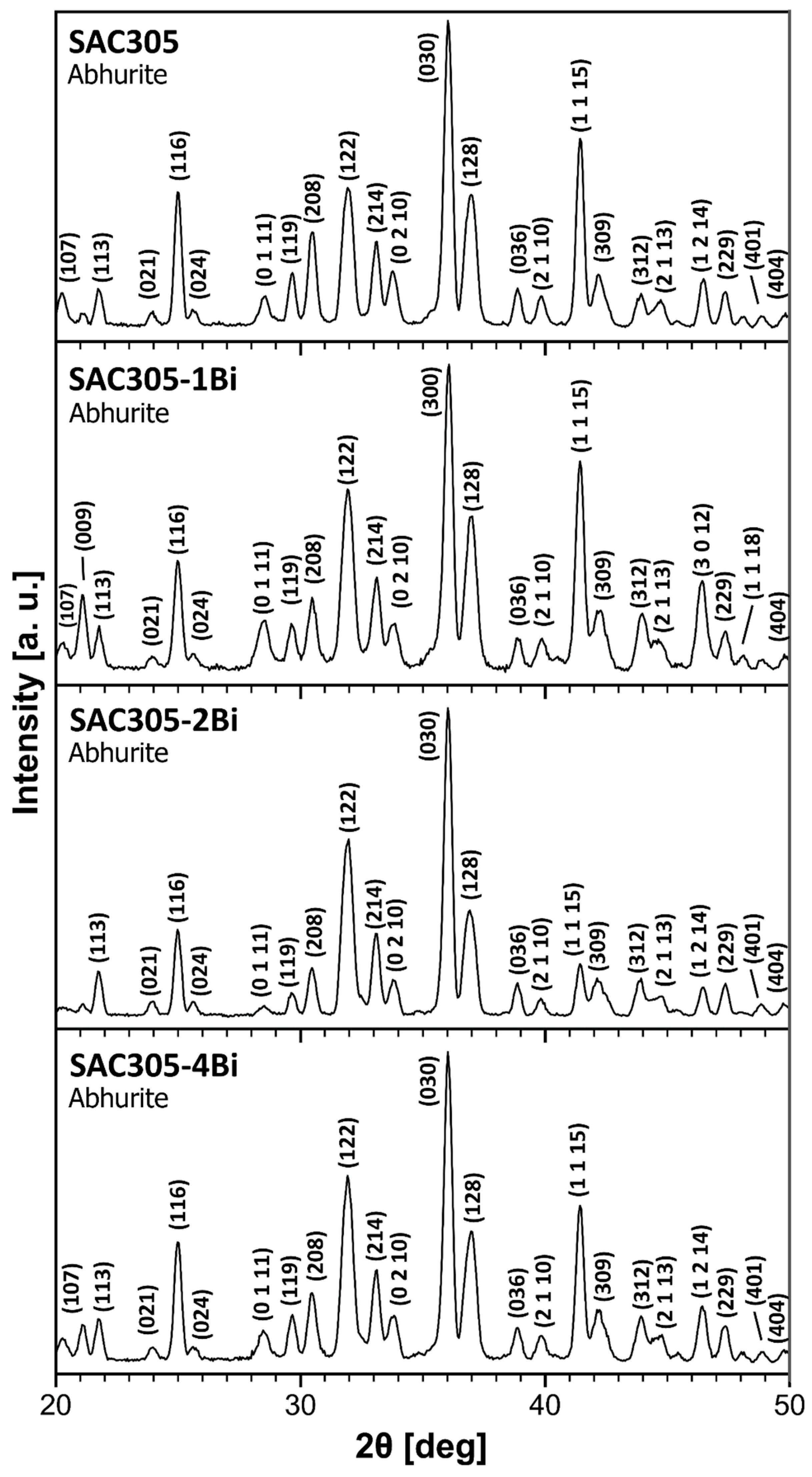
Structural identification of corrosion products was performed using X-ray diffraction in grazing incidence configuration (GI-XRD) on a PANalytical Empyrean diffractometer (Malvern Panalytical Ltd., Malvern, UK). It was equipped with a PIXcel 3D detector (Malvern Panalytical Ltd., Malvern, UK). Measurements using Co Kα radiation were performed over the angular 2θ range of 20–50°, using a step size of 0.05° and a counting time of 5 s per step. The incidence angle was 5°.
Phase identifications were performed using Malvern PANalytical X’Pert HighScore Plus software (version 5.1). Candidate phases were selected from the ICSD FIZ Karlsruhe database based on agreement with the measured diffraction patterns and the availability of complete crystallographic structure models, including atomic coordinates. Peak positions and profile shapes were first determined by automatic peak profile fitting and subsequently adjusted manually where required to obtain agreement with the experimental reflections. The Rietveld refinement based on true Voight profile function was used to describe the experimental GI-XRD peaks. An anisotropy size-strain model was applied to describe the full width at half-maximum (FWHM) of the peaks. The lattice parameters, coherent-domain size, and microstrain were obtained from the full diffraction profile rather than from a single diffraction reflection. Rietveld refinement were performed using Malvern PANalytical X’Pert HighScore Plus software (version 5.1). Only entries containing complete structural data, including atomic positions, and showing good agreement with the experimental pattern were used for subsequent refinement. Instrument broadening was determined from the X-ray diffraction pattern of LaB6, NIST Standard Reference Material 660c, collected in GI-XRD configuration. Lattice parameters, coherent diffraction domain size, and microstrain were obtained from the full-pattern Rietveld refinement. Preferred crystallographic orientation was treated using Spherical Harmonics.

3. Results and Discussion

3.1. Microstructure and Chemical Composition of SAC305-xBi Alloys

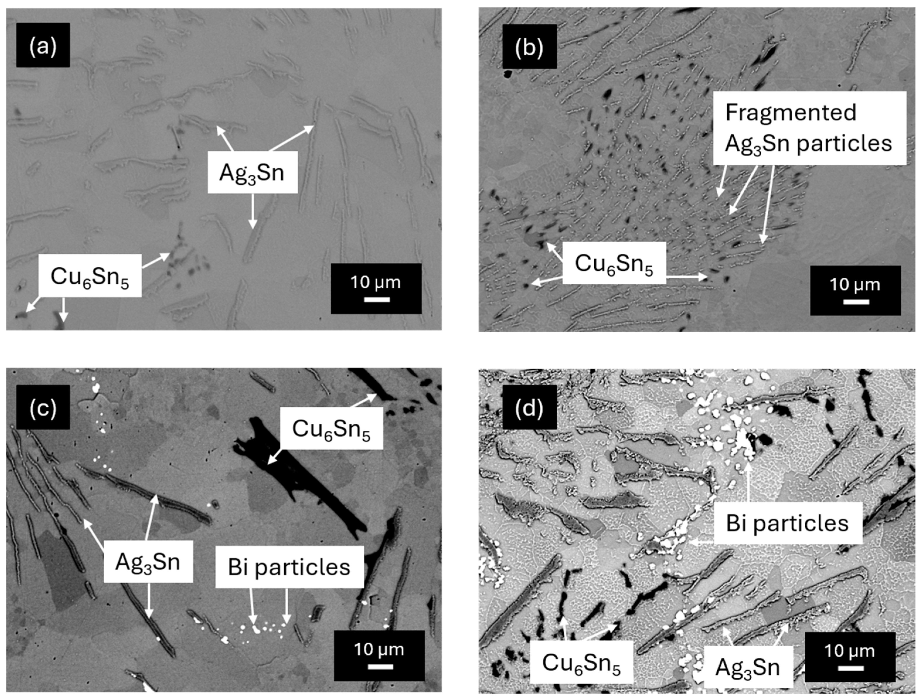
The microstructure of the alloys after casting is presented in Figure 1. Each alloy consists of a light-gray matrix. In the matrix, several different microstructure constituents were found. The microstructure constituents include long, light gray, lamella-shaped particles and black, mostly globular particles observed in all four alloys. The shape of the black particles varied with the concentration of Bi. In the SAC305-2Bi alloy, the black particles are larger and less fragmented (Figure 1c). Furthermore, in alloys with higher Bi content (SAC305-2Bi and SAC305-4Bi), small white granular particles were also found.
The SEM images were acquired in BSE imaging mode. Therefore, the black areas represent regions rich in elements with small atomic numbers (Cu). The light areas, on the other hand, are rich in heavier elements such as Bi and Sn. The microstructure of the SAC305-1Bi alloy represents a hypoeutectic microstructure with dendritic grains, presumably (Sn), and the ternary eutectic located in inter-dendritic regions. The ternary eutectic is a mixture of (Sn), Cu6Sn5 and Ag3Sn. It is formed by the following invariant reaction [32,33,34]:
L → (Sn) + Cu6Sn5 + Ag3Sn
The location of the ternary eutectic in the Sn-Ag-Cu system is at 3.5 wt. % Ag, 0.9 wt. % Cu and 95.6 wt. % Sn [32]. Since the alloys had a smaller Cu concentration than 0.9%, they were not fully eutectic. The solidification path of the alloys probably started with the formation of dendritic (Sn) grains. The precipitation of the eutectic took place in inter-dendritic spaces located between primary (Sn) grains formed during cooling.
The chemical composition of the matrix and intermetallic particles was studied using EDS point analysis. Results are presented in Table 1. The phase assignment presented in Table 1 was performed based on the chemical composition determined in the present study and the XRD analysis of the as-cast alloys reported in our previous work [21]. The Ag-rich lamellae can be assigned to Ag3Sn based on their chemical composition. The black particles can be assigned to Cu6Sn5 according to their chemical composition. The Sn-rich matrix was found to contain 99.6 at.% Sn and 0.4 at. % Bi. As such, it can be assigned to (Sn). Such microstructural heterogeneity, consisting of multiple phases with different electrochemical potentials, may significantly influence the corrosion behavior of the alloys.
The microstructure of the unmodified SAC305 alloy contains relatively distinct and well-developed Ag3Sn lamellae distributed within the inter-dendritic eutectic regions (Figure 1a). The lamellae are comparatively thick, clearly recognizable, and separated by relatively wide areas of the Sn-rich matrix. Cu6Sn5 particles are also present within the eutectic regions.
A markedly different Ag3Sn morphology is observed in the SAC305–1Bi alloy (Figure 1b). In this alloy, the Ag3Sn phase occurs predominantly as a large number of very thin, elongated, and partially fragmented particles. Instead of a smaller number of well-developed lamellae, the inter-dendritic regions contain a dense dispersion of fine Ag3Sn features with small interparticle distances. The individual particles retain an elongated morphology, but many of them are considerably shorter and thinner than the lamellae observed in the unmodified SAC305 alloy (Figure 1a).
The microstructure of the SAC305–2Bi alloy again contains more distinct and thicker Ag3Sn lamellae (Figure 1c). Their morphology is therefore more similar to that observed in SAC305 than to the fine and densely dispersed Ag3Sn phase in SAC305–1Bi. In addition, small bright Bi-rich particles are present in the inter-dendritic regions and in the vicinity of the Sn-rich matrix/Ag3Sn interfaces. A similar tendency is observed in SAC305–4Bi alloy. The Ag3Sn phase forms relatively well-developed lamellae that are thicker and less numerous than the fine elongated particles observed in SAC305–1Bi. The comparison therefore shows that SAC305–1Bi exhibits a distinct Ag3Sn morphology compared with the other investigated alloys. Whereas SAC305, SAC305–2Bi, and SAC305–4Bi contain relatively thicker and more clearly developed Ag3Sn lamellae, SAC305–1Bi is characterized by a considerably finer, more numerous, and more densely distributed population of thin elongated Ag3Sn particles. This observation indicates that the addition of 1 wt. % Bi modified the solidification morphology of the Ag3Sn-containing eutectic regions differently from the additions of 2 and 4 wt. % Bi.
In the SAC305-2Bi and SAC305-4Bi alloys, a segregation of (Bi) particles was observed (Figure 1c,d). In the SAC305-1Bi alloy, however, the segregation of (Bi) was not found, probably due to low Bi concentration (Figure 1b). Bi has a relatively high solid solubility in (Sn), up to 21 wt. % at the eutectic temperature [25]. The (Bi) particles were located at the (Sn)–Ag3Sn interface in the inter-dendritic spaces of the (Sn) solid solution (Figure 1c,d). Therefore, the Bi-rich particles have probably been formed as a secondary phase. The presence of Bi-rich particles at phase boundaries may promote the formation of local micro-galvanic cells, which can affect the corrosion resistance of the alloys. Their formation may be related to the local formation of a supersaturated solid solution of Sn. A change in the solubility of Bi in (Sn) with temperature may result in the precipitation of (Bi) from the supersaturated solid solution of Sn according to the following reaction [21]:
(Sn)ss → (Sn) + (Bi)
Another possibility for the precipitation of (Bi) particles could be the formation of a binary eutectic (Sn) + (Bi) in the inter-dendritic spaces between (Sn) dendrites. The formation of the binary (Sn) + (Bi) eutectic from the remaining melt can be given by the following equation [21]:
L → (Bi) + (Sn)
Both these reactions are feasible. The extent to which the reaction prevails depends on the chemical composition of the solder and non-equilibrium processes taking place during casting.
An overall chemical composition of the alloys was also studied. The chemical composition was measured by EDS from large surface areas for each solder. The average values and standard deviations obtained from three independent measurements are presented in Table 2. The nominal composition of the alloys is included in the same table for the sake of comparison. Only small differences were observed, e.g., slightly higher Ag contents in the SAC305 and SAC305-4Bi alloys were found. This observation could be related to the as-cast condition of the alloys, mainly local heterogeneities such as larger sizes of Ag3Sn lamellae compared to Cu6Sn5 and (Bi) particles and their location in inter-dendritic regions (Figure 1). Overall, the chemical composition of the SAC305-xBi alloys agreed well with their nominal chemical composition. Therefore, the evolution of the microstructure with increasing Bi content, particularly the formation and distribution of Bi-rich phases, is expected to play an important role in the electrochemical behavior of the SAC305–xBi alloys.

3.2. Corrosion Performance of the SAC305-xBi Alloys

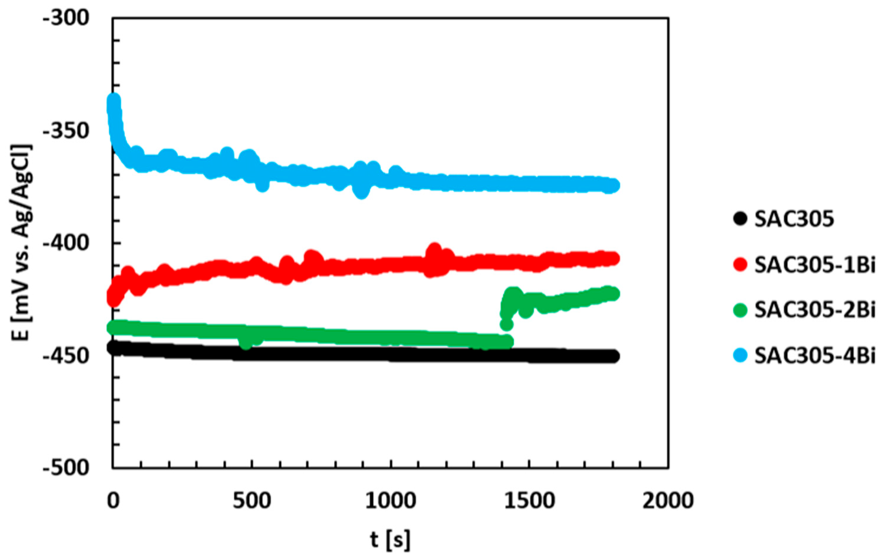
The corrosion resistance of the alloys was assessed in NaCl electrolyte, chosen to mimic typical marine conditions the alloys may experience during operation. The open-circuit potential (OCP) was recorded from the moment of immersion up to 30 min. The representative measured OCP values are presented in Figure 2. The OCP of the SAC305 alloy was relatively stable over time. The relatively stable OCP of SAC305 indicates that a passive layer quickly formed on the surface of the unmodified alloy. The open circuit potentials of the SAC305-xBi alloys (x = 1, 2, 4), on the other hand, were found to vary with time. Furthermore, small oscillations in the OCPs were observed. These observations indicate that active electrochemical processes may have taken place at the surfaces of the alloys during their exposure to saline solution.
The OCP of the SAC305-1Bi alloy was found to increase over time (Figure 2). This observation indicates that a passive layer progressively formed on the surface of this alloy. The same observation was also found for the SAC305-2Bi alloy (Figure 2). The OCP of the SAC305-4Bi alloy, however, was found to decrease over time. This observation may indicate active corrosion processes having taken place at the surface of the SAC305-4Bi alloy.
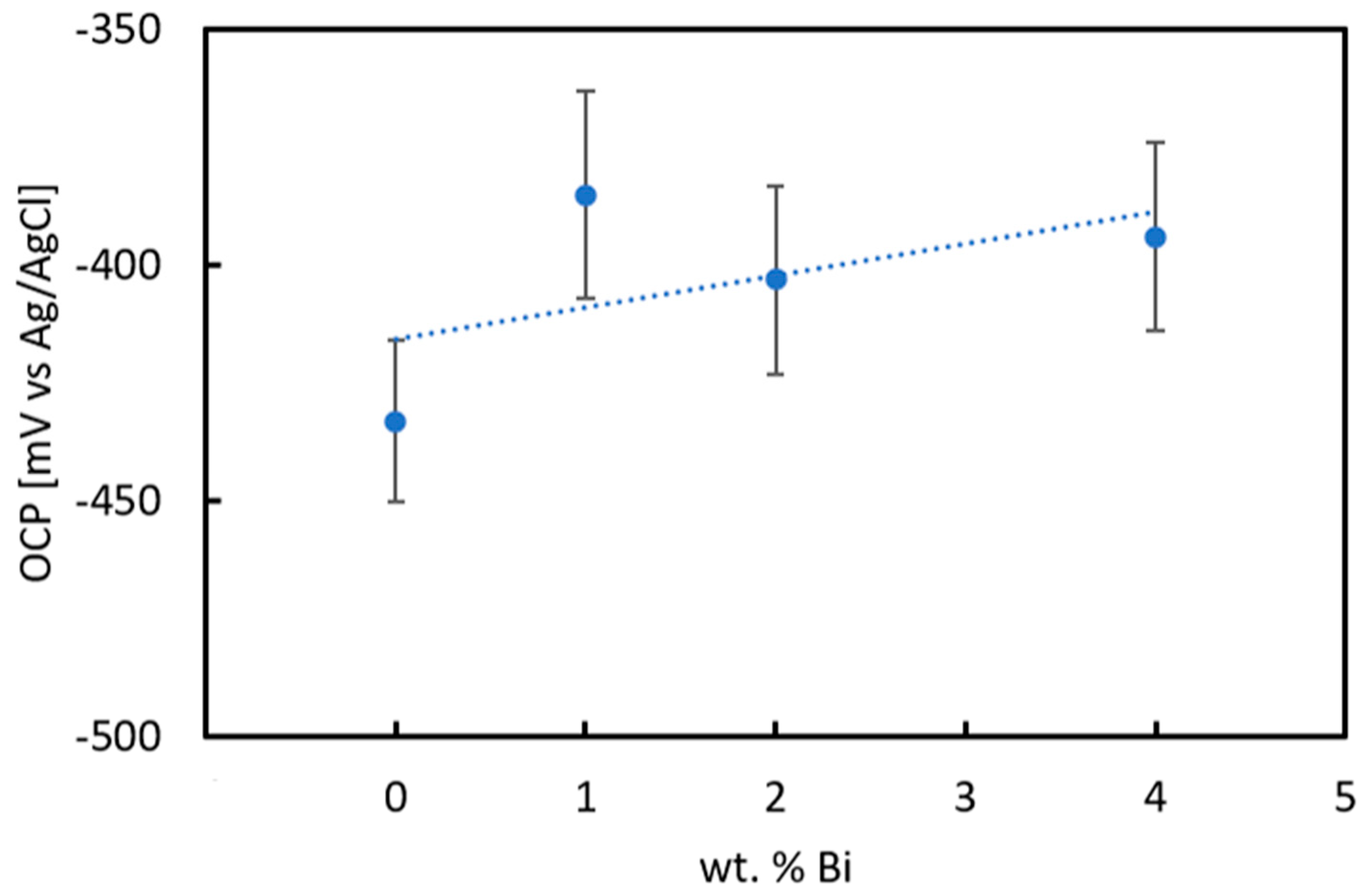
The OCPs of the alloys measured after 30 min of immersion are compared in Figure 3. The OCPs increase with increasing concentration of Bi. The higher OCPs indicate higher nobility. This observation indicates that Bi alloying elevates the nobility of the alloys. However, differences between the Bi-alloyed materials were also found. For example, the OCP of the SAC305-2Bi alloy was lower compared to the SAC305-1Bi alloy (Figure 2). It is possible that distinct Bi particles, which were present in the SAC305-2Bi alloy but absent in the SAC305-1Bi alloy, contributed to higher activity of the SAC305-2Bi alloy. It is also feasible that micro-galvanic cells between the different microstructure constituents in the SAC305-2Bi alloy formed and contributed to higher corrosion activity of this alloy.
The OCPs of the SAC305-xBi alloys are comparable to SAC alloys previously studied [19]. Furthermore, the OCP values correspond to the corrosion potential of Sn. This observation indicates that preferential dissolution of Sn was most probably also taking place in the SAC305-xBi alloys. Most Sn is present in (Sn). Therefore, this phase is prone to corrosion. However, the presence of Bi dissolved in (Sn) contributed to the ennoblement of this phase [25]. As such, it can be concluded that OCPs of the SAC305-xBi alloys increased with increasing Bi concentration because of the ennoblement of the (Sn) phase.
The OCP of the SAC305-4Bi alloy was the highest among the studied alloys (Figure 3). Therefore, this alloy was the noblest. However, the OCP of the SAC305-4Bi alloy was also found to decrease over time (Figure 2). Furthermore, small oscillations were found, indicative of active electrochemical processes taking place at the surface of this alloy. The active electrochemical processes could be related to microstructural heterogeneities, such as the excessive segregation of (Bi) particles in the alloy (Figure 1) and the formation of micro-galvanic cells.
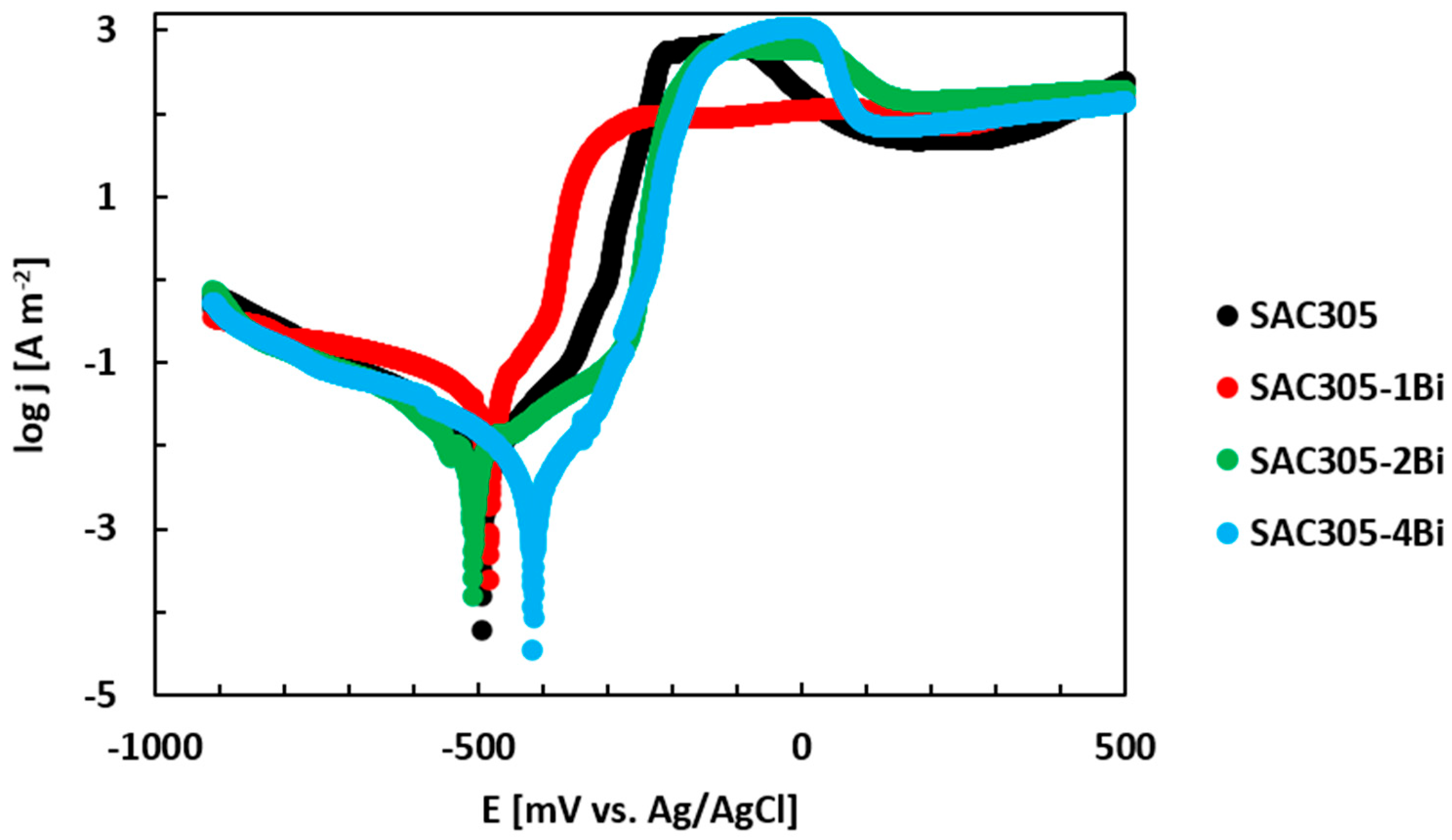
The corrosion performance of the SAC305-xBi alloys was further studied by potentiodynamic polarization. The measurement was initiated after the OCP experiment. The potential of the SAC-xBi alloy was increased linearly from −900 mV to +500 mV vs. Ag/AgCl using a sweeping rate of 1 mV/s to record the cathodic and anodic responses. The experiment was controlled using a potentiostat. The results are compared in Figure 4. Each polarization curve consists of several different regions. The first region, recorded at electrode potentials lower than ~ −500 mV vs. Ag/AgCl, represents an immune (cathodic) region [35]. At small potentials, the alloy is thermodynamically stable, and the cathodic reaction (reduction of cations) is assumed to take place at the metallic surface exposed to the electrolyte. The next region, the anodic region, is observed when the corrosion (initiation) potential has been passed. In the anodic region, the oxidation of the alloy takes place, and the metal surface actively dissolves in the electrolyte.
The polarization curves of the SAC-xBi alloys were analyzed using Tafel extrapolation to obtain the corrosion potential (Ecorr) and corrosion current density (jcorr) of the alloys. The results are given in Table 3. It can be observed that the corrosion potentials of the SAC–xBi alloys increase with increasing Bi concentration. This observation agrees with the evolution of the OCPs and reflects the higher electrochemical nobility of Bi compared to that of Sn.
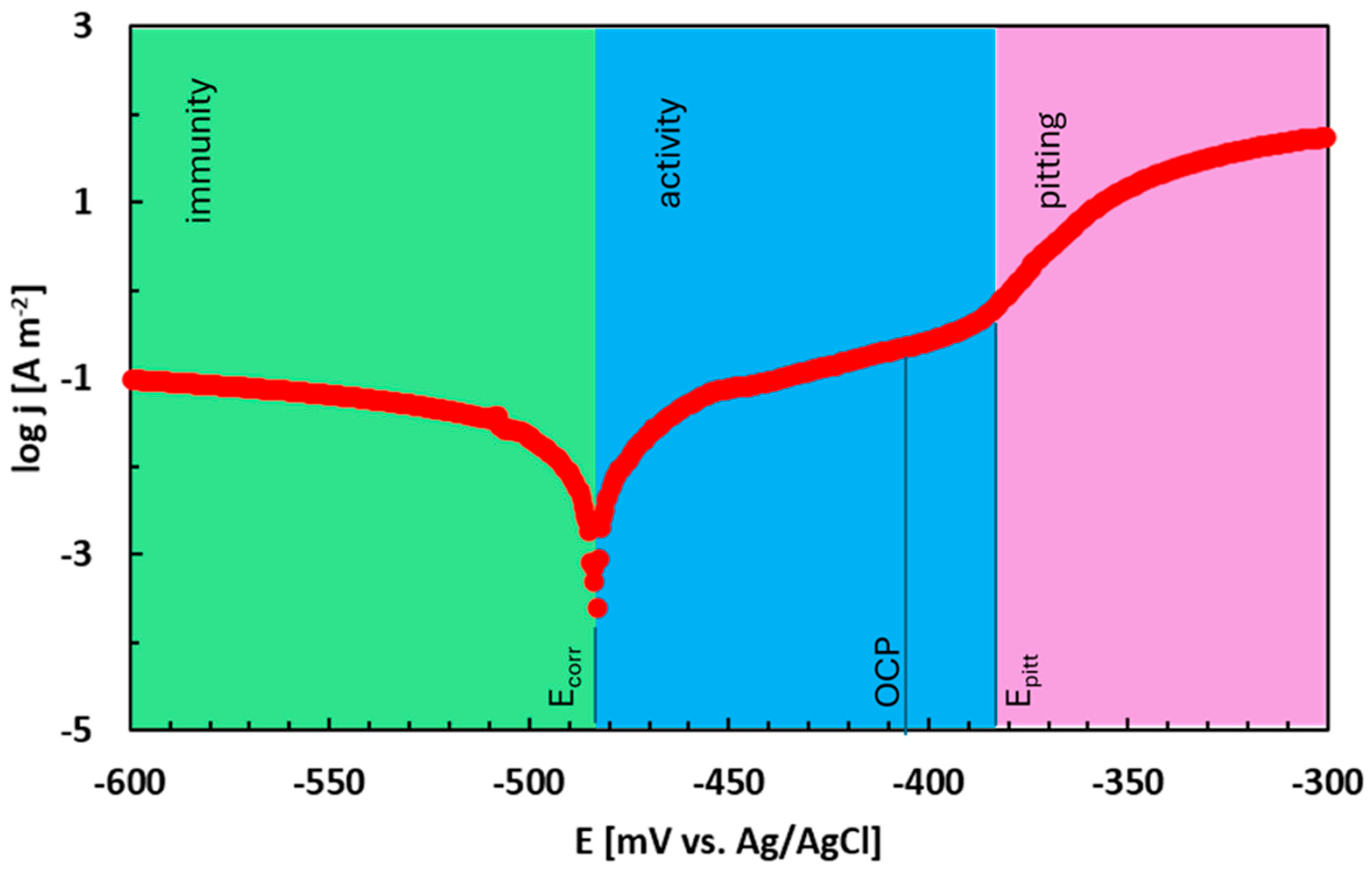
A steady increase in the current density at high electrode potentials was observed on all polarization curves (Figure 4). The observed marked increase in current density is indicative of pitting [19,36,37]. In Cl-containing solutions, the passive layer formed on the surface is prone to local corrosion (pitting). The pit formation is initiated by the presence of Cl anions in the electrolyte and leads to the destruction of the passive layer. Pitting corrosion is observed when the pitting potential is surpassed. The location of the pitting potential is shown in Figure 5 on the polarization curve of the SAC305-1Bi alloy. The pitting potentials (Epitt) of the SAC–xBi alloys are noted in Table 3.
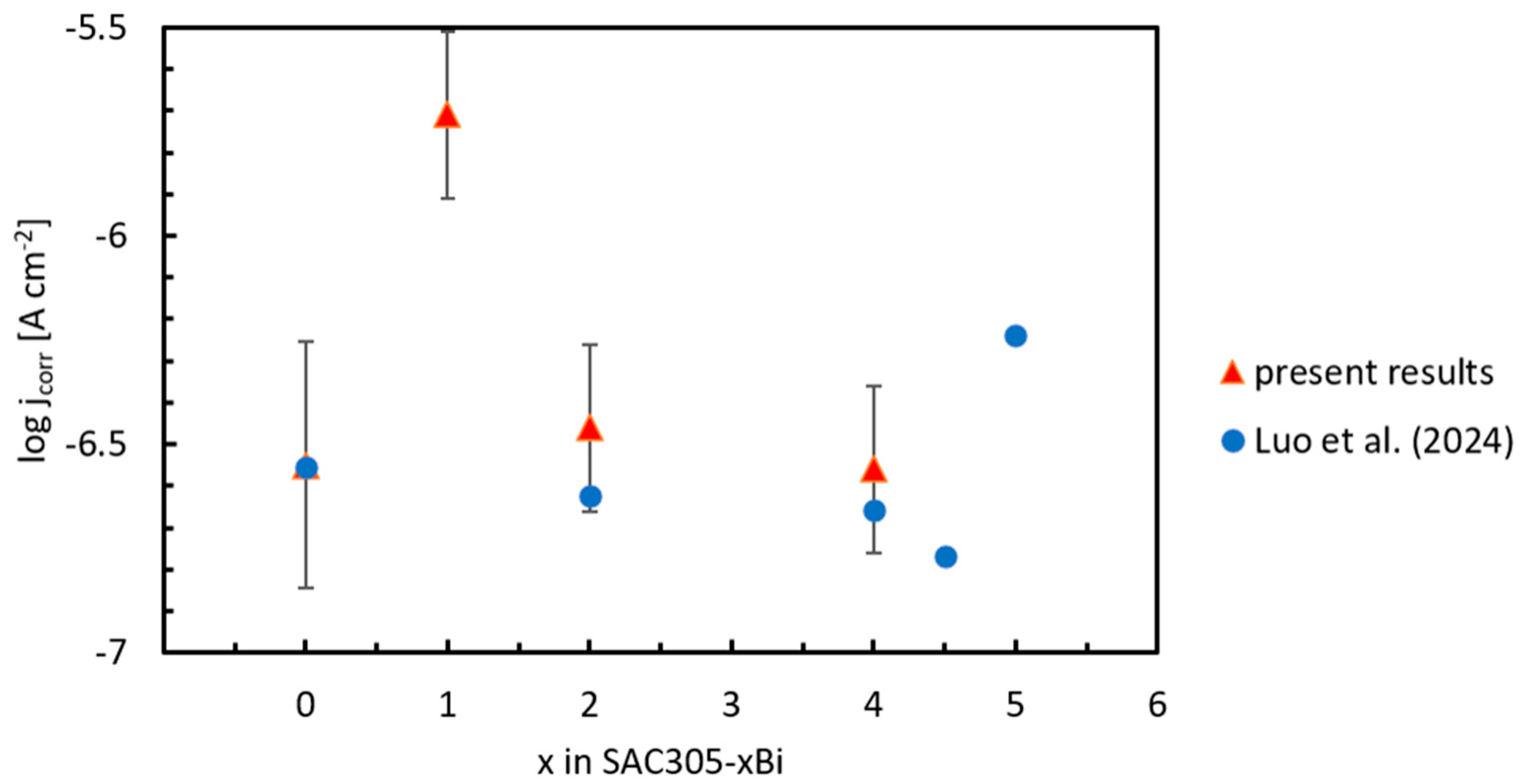
The pitting potentials of the SAC305-xBi alloys increase with increasing Bi concentration (Table 3). The pitting potentials of the SAC305-2Bi and SAC305-4Bi alloys are higher compared to the SAC305 alloy. Furthermore, their open circuit potential is significantly lower compared to the pitting potential (Table 3). As such, these alloys have a corrosion resistance that is higher compared to the SAC305 alloy. Nevertheless, the pitting potential of the SAC305-1Bi alloy is lower compared to that of the SAC305 alloy. Furthermore, the corrosion current of this alloy is the highest among the studied alloys (Figure 6). These observations together indicate a lower corrosion resistance of the SAC305-1Bi alloy.
The difference between Ecorr and Epitt can be used as a measure indicative of the stability of the passive layer. This difference is included in Table 3. The largest difference between the corrosion and pitting potentials is observed for the SAC305-2Bi alloy. The lowest difference between the corrosion and pitting potentials is observed for the SAC305-1Bi alloy. These observations indicate that the SAC305-1Bi alloy is prone to pitting corrosion.
The strikingly different corrosion resistance of the SAC305-1Bi and SAC305-2Bi is unexpected, as it has not been previously reported. Since these two alloys had different microstructure constituents, corrosion behavior could be related to the existence of different micro-galvanic cells. Furthermore, the SAC305–1Bi alloy differs from the remaining alloys by the morphology and number density of the Ag3Sn particles. In the SAC305, SAC305–2Bi, and SAC305–4Bi alloys, Ag3Sn occurred mainly as relatively well-developed and thicker lamellae. In contrast, SAC305–1Bi contained a high portion of very thin, elongated, and partially fragmented Ag3Sn particles distributed densely within the inter-dendritic regions (Figure 1b).
The electrochemical effect of an intermetallic phase is not controlled only by the size of an individual particle. The number of particles, their spacing, spatial connectivity, and total interfacial contact with the surrounding Sn-rich matrix are also important. Even if the total amount of Ag3Sn remains similar because the nominal Ag content is constant, fragmentation of the phase into a larger number of finer particles may substantially increase the total length and density of the β-Sn/Ag3Sn interfaces exposed at the alloy surface.
Ag3Sn is electrochemically more noble than the surrounding Sn-rich matrix. Consequently, local micro-galvanic coupling can develop at β-Sn/Ag3Sn interfaces, with Ag3Sn supporting cathodic reactions and the adjacent Sn-rich matrix undergoing preferential anodic dissolution. As a first approximation, standard electrode potentials of constituent elements of the SAC305-xBi alloys have been compared. The values are collected in Table 4 [38]. The electrode potentials increase in the following order:
E0 (Sn) ˂ E0 (Bi) ≈ E0 (Cu) ˂ E0 (Ag)
Ag is the most noble element. Sn, on the other hand, is the least noble. Because of large differences in electrode potentials of the constituent elements, Sn could be preferentially oxidized in the SAC305-xBi alloys. Bi is nobler compared to Sn (Table 4). As such, it is less likely to be oxidized in the SAC305-xBi alloys. Furthermore, the standard electrode potential of Bi is very close to that of Cu. Therefore, Bi precipitates are unlikely to significantly increase the corrosion rate of the SAC305-xBi alloys. In fact, the SAC305, SAC305-2Bi and SAC305-4Bi alloys had comparable corrosion currents despite having different Bi concentrations (Figure 6). This observation indicates that Bi particles do not decrease the corrosion resistance significantly.
The SAC305 and SAC305-1Bi alloys did not contain any Bi particles precipitated in the bulk (Figure 1). All Bi in the SAC305-1Bi alloy was found to be dissolved in (Sn). However, the corrosion current of the SAC305-1Bi alloy was found to be significantly higher compared to the Bi-free SAC305 alloy (Figure 6). This difference could be related to heterogeneities observed in the microstructure of the SAC305-1Bi alloy. In the SAC305 alloy, the microstructure constituents were evenly distributed (Figure 1a). However, Cu6Sn5 and Ag3Sn particles in the SAC305-1Bi alloy were preferentially located in inter-dendritic spaces between the (Sn) grains (Figure 1b). As such, they could initiate micro-galvanic corrosion. Further insights into the corrosion behavior of the SAC305-xBi alloys have therefore been obtained by investigating the post-corroded surfaces of the alloys.
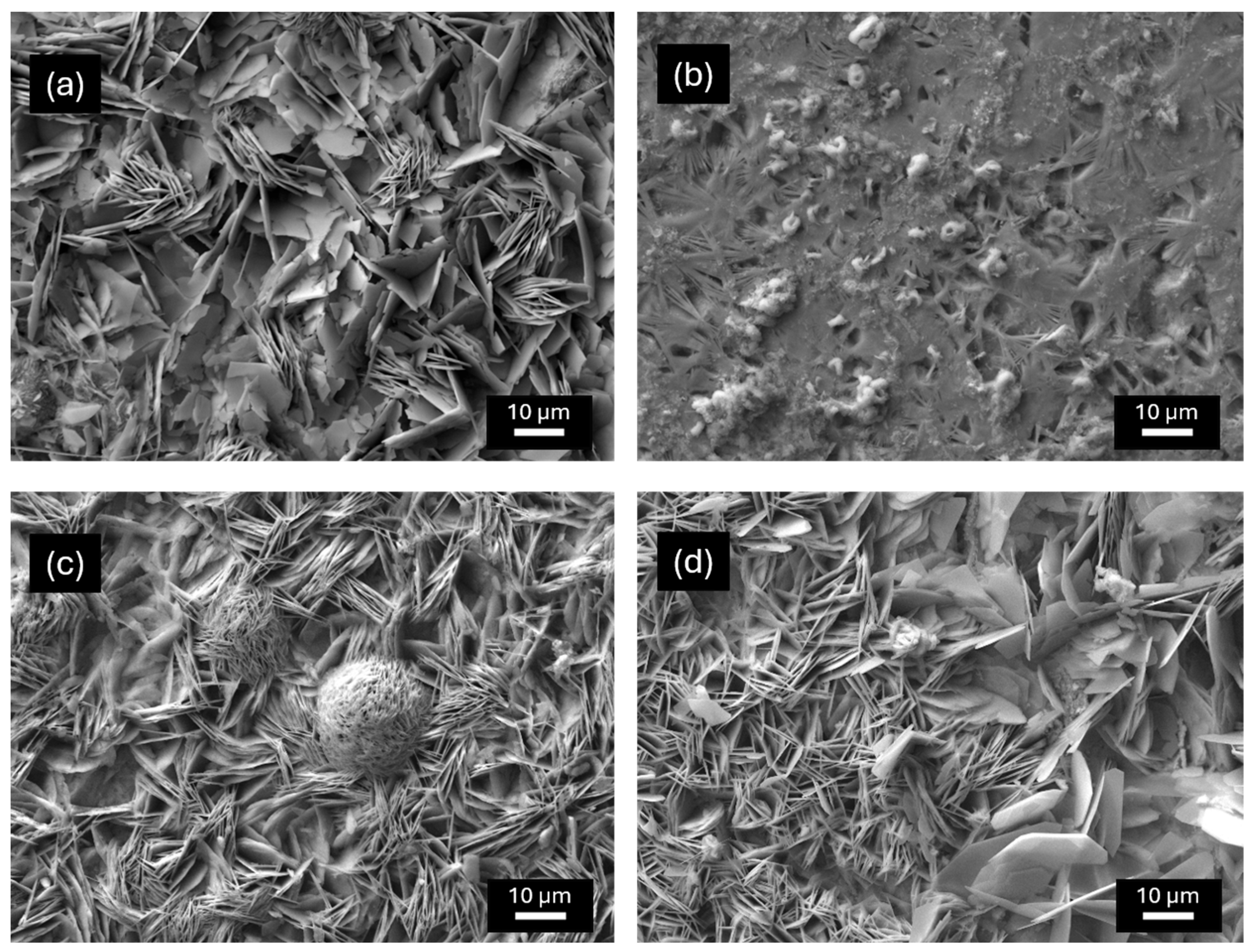
The microstructure of post-corroded alloys is presented in Figure 7. Each of the alloys was covered by a layer of corrosion products. The corrosion products consisted of large plate-like crystallites and whiskers observed on the surface of the SAC305, SAC305-2Bi and SAC305-4Bi alloys (Figure 7a,c,d). However, in the case of the SAC305-1Bi alloy, a different microstructure was observed. The crystallites were smaller, and the scale was less adherent and partially spalled off (Figure 7b). Thus, the original alloy surface was exposed.
The microstructure features given in Figure 7b for the SAC305-1Bi alloy are indicative of localized corrosion attack. This observation is in accordance with potentiodynamic experiments since the SAC305-1Bi alloy had the lowest pitting potential (Table 3). As such, it was prone to local corrosion. The chemical composition of corrosion products was further studied using EDS. The scale was found to be composed of Sn, O and Cl. The elements were distributed evenly on the surface of the SAC305, SAC305-2Bi and SAC305-4Bi alloys, suggesting the formation of a complete, fully adhering scale. The chemical composition of the scale on the SAC305 alloy found experimentally was 26.5 at. % Sn, 19.7 at. % Cl, 53.82 at. %. O (Table 5). A similar chemical composition of the corrosion product was also found on the surface of the SAC305-2Bi and SAC305-4Bi alloys, suggesting a similar corrosion mechanism.
The chemical composition of corrosion products formed on the surface of the SAC305-1Bi alloy is also given in Table 5. In this alloy, the scale had a higher concentration of O (65.8 at. %) compared to the remainder of the alloys. This result is indicative of more severe corrosion attack of the SAC305-1Bi alloy compared to the remainder of the alloys.
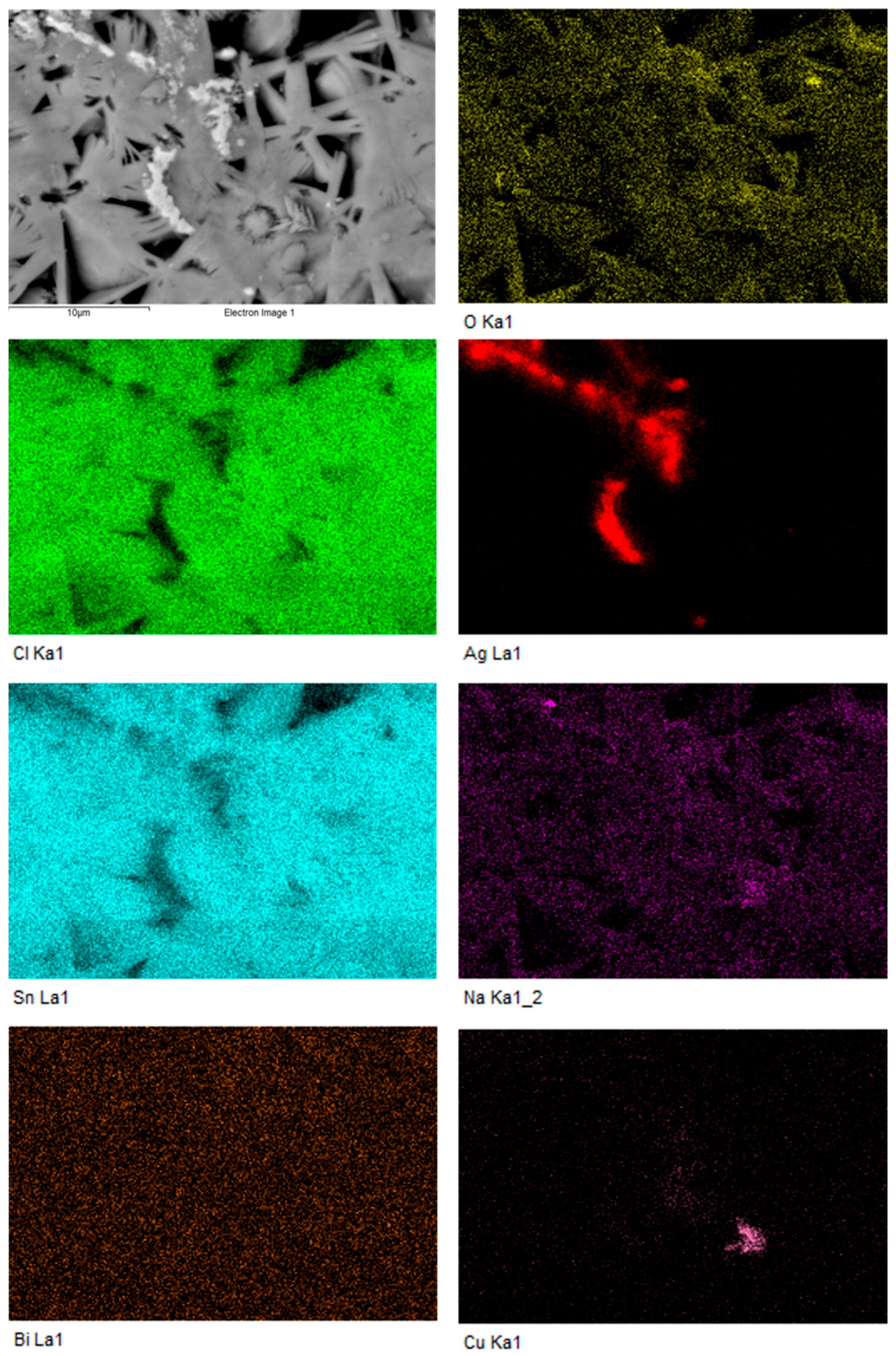
The detail of the corrosion layer formed on the surface of the SAC305-1Bi alloy is provided in Figure 8. The corrosion layer was less adherent compared to the remainder of the alloys, locally spalled, and exposed portions of the underlying substrate were observed. The chemical composition of the post-corroded surface of the SAC305-1Bi alloy was further studied by EDS mapping. The result is presented in Figure 8. EDS mapping indicated that the localized disruption of the layer occurred in the vicinity of Ag3Sn-containing regions. The fine and dense Ag3Sn dispersion may therefore promote the simultaneous initiation of corrosion at numerous neighboring β-Sn/Ag3Sn interfaces. Coalescence of these locally attacked regions may undermine the developing corrosion product layer and reduce its mechanical support by the substrate.
The distinct corrosion pathway of the SAC305-1Bi alloy was further studied by the GI-XRD analysis of the corrosion products. Results are presented in Figure 9. GI-XRD analysis identified the rhombohedral abhurite phase (space group R32) in the corrosion products formed on all investigated alloys. XRD analysis of corrosion products confirmed the formation of an identical crystalline phase in all investigated samples, which was identified as trigonal Abhurite with a rhombohedral lattice. No other crystalline corrosion products were detected. Therefore, the different morphology of the corrosion product formed on the surface of SAC305-1Bi observed by SEM (Figure 7b) is not related to the formation of a different corrosion product phase.
The results of the refinement of the lattice parameters, crystallite sizes, and microstrain of abhurite are given in Table 6. The values of the lattice parameter (a) differed only slightly between the individual samples. A more significant difference was observed for the lattice parameter (a) of the SAC305-1Bi sample. The abhurite formed on the SAC305-1Bi sample differed from the other samples by the smallest average crystallite size and, at the same time, it had the highest microstress. Thus, the alloy with 1 wt. % Bi showed a clearly different crystallographic state of the corrosion product compared to the SAC305, SAC305-2Bi and SAC305-4Bi alloys.
The results of the SAC305-1Bi alloy indicate that the effect of the Bi content on the morphology of the corrosion product is not linear. Since the XRD analysis identified the same corrosion product in all samples, the difference in morphology observed by SEM (Figure 7b) is probably related to different nucleation and growth of the same product phase. The SAC305-1 Bi alloy was also characterized by the most pronounced deviation of the lattice parameter, higher microstrain, and smaller crystallite size compared to the remainder of the alloys (Table 6). This deviation may not be a direct cause of the different morphology; however, it could be indicative of either a different crystallographic or stress state of abhurite (for example, different microstrain, texture, crystallite size, or residual stresses).
The morphology of the underlying substrate may also influence the nucleation and growth of abhurite. In SAC305, SAC305–2Bi, and SAC305–4Bi, the lower number density of thicker Ag3Sn lamellae may provide fewer spatially concentrated sites of preferential Sn dissolution. Under such conditions, the corrosion product may nucleate at a lower number of locations and subsequently grow into larger plate-like crystallites and whisker-like features. By contrast, the large number of fine Ag3Sn particles in SAC305–1Bi may generate a high density of local dissolution and precipitation sites. The corrosion product may consequently undergo repeated nucleation at many closely spaced locations rather than unrestricted growth of a smaller number of existing crystallites.
Such a nucleation-dominated growth mode is consistent with the smaller coherent-domain size obtained for abhurite on SAC305–1Bi. A high density of independently nucleated crystallites can also produce a greater number of crystallite boundaries, lattice defects, and local mismatch stresses within the corrosion layer. These effects provide a plausible explanation for the higher microstrain determined for the abhurite formed on SAC305–1Bi. The measured microstrain, however, should not be considered as a direct proof of a particular defect mechanism. Nevertheless, together with the finer corrosion-product morphology and reduced layer adhesion, it indicates that the abhurite layer on SAC305–1Bi developed in a more highly defected and mechanically constrained state. The higher internal heterogeneity of the layer may have contributed to cracking and spallation during corrosion.

3.3. Corrosion Mechanism of the SAC305-xBi Alloys

Repeated local dissolution of the substrate beneath the layer, combined with the growth of numerous fine abhurite crystallites, may generate non-uniform volume changes and local stresses at the corrosion-product/substrate interface. Once the layer locally separates from the substrate, the fresh alloy surface becomes exposed to the electrolyte. Therefore, repeated exposure of fresh Sn-rich regions can sustain anodic dissolution and prevent the establishment of a stable and fully adherent corrosion layer. This interpretation agrees with the higher corrosion current density and lower resistance to localized corrosion observed for SAC305–1Bi.
The results presented in the preceding chapter are indicative of preferential Sn dissolution in the SAC305-xBi alloys. This reaction can be given by the following reaction
S n S n 2 + + 2 e
This anodic reaction is counter-balanced by a cathodic reaction. Since the electrolyte had not been de-aerated, the cathodic reaction can be assumed to be a reduction of O2 dissolved in the electrolyte. This reaction can be given by the following equation [39].
1 2 O 2 + 2 e + H 2 O 2 O H
By combining Equations (5) and (6), we get the following overall reaction
1 2 O 2 + S n + H 2 O S n O H 2
Tin hydroxide, Sn(OH)2, is a transient corrosion product. It represents a hydrated tin monoxide (SnO.H2O [40]). Since Cl ions were also present in the electrolyte, some OH anions in Sn(OH)2 have been replaced by Cl. This reaction can be expressed by the following equation
3Sn(OH)2 + 2Cl → Sn3O(OH)2Cl2 + 2OH + H2O
Reaction (8) explains why Cl atoms were also found to be present in the corrosion product (Table 4). Sn3O(OH)2Cl2 represents a hydrated tin oxy-chloride (2SnO.SnCl2.H2O), which was identified as abhurite by GI-XRD analysis (Figure 9). It is commonly observed during the oxidation of tin alloys in saline solutions [20,41].
The corrosion product formed on the surface of the SAC305 alloy had been previously studied [40,42]. The results revealed that the scale mainly consisted of a SnO/SnO2 layered structure with thickness increasing slightly from approximately 16.5 nm to 18 nm, with increased micro-cracks and Ag3Sn coarsening induced by the Kirkendall effect. The coarsening of Ag3Sn was observed to lead to a significant reduction in corrosion resistance. Our findings demonstrate that the degradation of the scale is also governed by the coupled effects of defect accumulation and fragmentation (Figure 8).
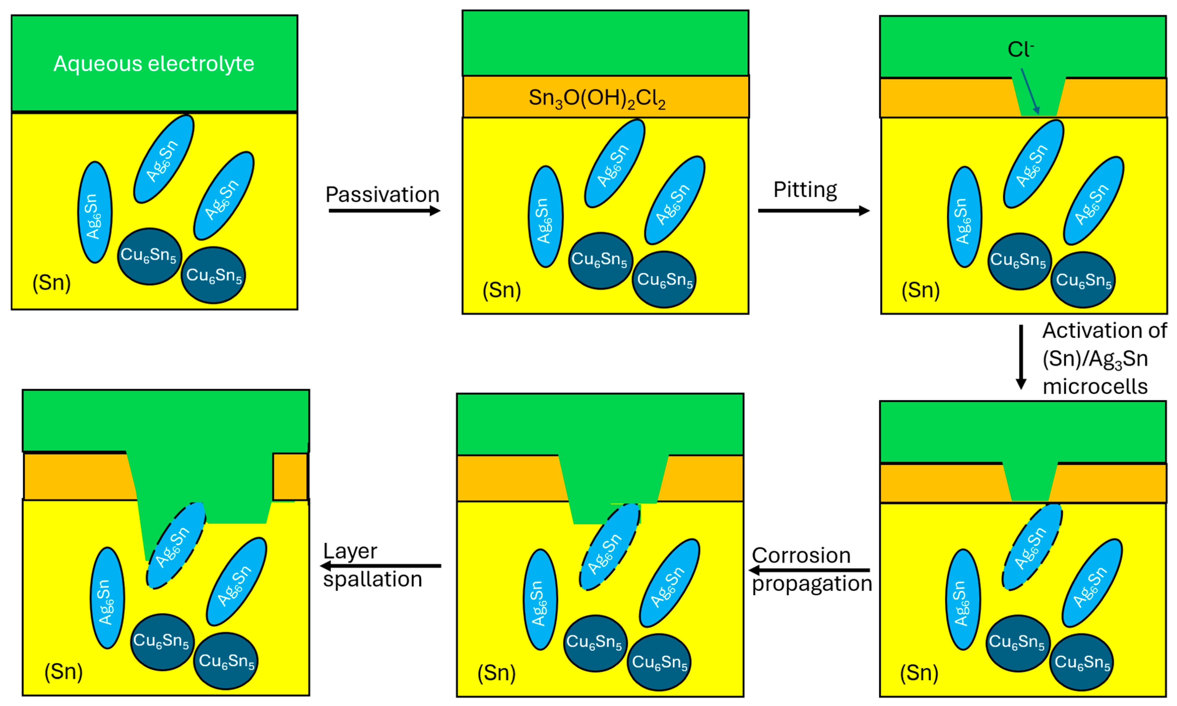
The corrosion mechanism of the SAC305-1Bi alloy in the aerated NaCl solution is presented in Figure 10. At the beginning of exposure, the pristine alloy surface is attacked by oxygen and other ions dissolved in the aqueous electrolyte. As a result of the attack, a corrosion scale is formed. The scale may be initially protective. However, during prolonged exposure to Cl-containing environments, cracks and defects may start to develop. The cracks lead to the exposure of the underlying substrate.
Due to a large difference in standard electrode potentials between Ag and Sn (Table 4), galvanic microcells are likely to form at the (Sn)Ag3Sn interface. This difference leads to preferential Sn dissolution. In chloride-containing environments, structural defects within the corrosion product layer are formed due to reaction of the scale with Cl ions. The defects provide diffusion pathways for Cl ions. As such, Cl ions may function as catalytic species. They may accelerate defect generation and transport, thereby promoting the progressive degradation of the oxide film. Furthermore, voids and other defects are formed due to possible de-alloying of Ag3Sn and may lead to further destabilization.
The micro-galvanic cells at the Sn–Ag3Sn interface were the initiating factors of pitting corrosion in the SAC305-1Bi alloy (Figure 8). In the SAC305-1Bi alloy, the Ag3Sn phase occurred predominantly as a large number of very thin, elongated, and partially fragmented particles. Instead of a smaller number of well-developed lamellae, the inter-dendritic regions contained a dense dispersion of fine Ag3Sn features with small interparticle distances. The individual particles retained an elongated morphology, but many of them were considerably shorter and thinner than the lamellae observed in the unmodified SAC305 alloy. The electrochemical effect of an intermetallic phase is given by the size and number of particles, their spacing, spatial connectivity, and total interfacial contact with the surrounding Sn-rich matrix. Even if the total amount of Ag3Sn in the alloys was similar, the fragmentation of this phase into a larger number of finer particles substantially increased the total length and density of the β-Sn/Ag3Sn interfaces exposed at the alloy surface. The fine and dense Ag3Sn dispersion therefore promoted the simultaneous initiation of corrosion at numerous neighboring β-Sn/Ag3Sn interfaces. Coalescence of these locally attacked regions undermined the developing corrosion product layer and reduced its mechanical support by the substrate.
On the other hand, the presence of Bi precipitates in the SAC305-2Bi and SAC305-4Bi alloys partially reduced the risk of galvanic corrosion. The Bi precipitates were observed to accumulate next to Cu6Sn5 and Ag3Sn particles (Figure 1c,d). Since Bi has a higher standard electrode potential compared to Sn, the Bi/Ag3Sn and Bi/Cu6Sn5 couples are less likely to corrode [20]. However, the beneficial effect of Bi on the corrosion resistance of the SAC305 alloys has a certain limit. It has been observed that the addition of higher amounts of Bi (more than 4.5 wt. %) leads to an increase in corrosion activity [19]. Therefore, Bi-rich particles should not be interpreted simply as universally protective constituents. Owing to their electrochemical nobility relative to Sn, they may also participate in local galvanic interactions. However, their presence changes the topology of the multiphase microstructure. Bi-rich particles located near Ag3Sn or Cu6Sn5 may modify the direct contact geometry between the Sn-rich matrix and the intermetallic phases, redistribute local cathodic activity, and alter the number and spatial arrangement of preferential dissolution sites. The formation of discrete Bi-rich particles at 2 and 4 wt. % Bi may therefore partially compensate for, or reorganize, the electrochemical effect associated with Bi dissolved in the Sn-rich matrix.
Bi-rich particles do not suppress the corrosion activity directly. Rather, the combination of distinct Bi-rich precipitates and thicker, less densely distributed Ag3Sn lamellae creates a different micro-galvanic configuration from that present in SAC305–1Bi. In SAC305–2Bi and SAC305–4Bi, local electrochemical reactions may be distributed over fewer or more spatially separated interfacial regions, allowing the abhurite layer to develop more uniformly. This interpretation is consistent with the similarity of the corrosion-product morphology observed on SAC305, SAC305–2Bi, and SAC305–4Bi alloy surfaces. It is likely that Bi alloying plays a dual role. While Bi is dissolved in the (Sn) matrix, it contributes to the ennoblement of the alloys. However, the presence of large amounts of discrete particles rich in Bi also causes microstructural heterogeneity. If these heterogeneities are excessive, they may promote the formation of micro-galvanic cells between the (Sn) matrix and noble intermetallic compounds (Ag3Sn, Cu6Sn5). Therefore, the corrosion resistance of SAC305–xBi alloys also depends on the distribution and morphology of individual phases in the microstructure. Our results suggest that the presence of Bi-rich precipitates in the SAC305-2Bi and SAC305-4Bi alloys modified the local galvanic interactions; however, their direct negative effect on the corrosion resistance could not be conclusively established.
The results presented above support the following mechanistic interpretation: In the SAC305–1Bi alloy, the refinement and fragmentation of Ag3Sn increase the density of β-Sn/Ag3Sn interfaces. These interfaces provide numerous sites for local micro-galvanic interactions and preferential dissolution of the adjacent Sn-rich matrix. The resulting high density of local reaction sites promotes repeated nucleation of abhurite, producing a corrosion layer with smaller coherent domains, higher microstrain, and reduced adhesion. Local spallation repeatedly exposes fresh substrate and sustains corrosion. In the SAC305, SAC305–2Bi, and SAC305–4Bi solders, the lower number density of thicker Ag3Sn lamellae and, in the Bi-containing alloys, the additional presence of discrete Bi-rich particles favors more uniform growth of the abhurite layer.
It should be noted that the above-given mechanism remains a microstructure-based interpretation rather than direct proof of the local electrochemical activity of the individual phases. Quantitative image analysis of Ag3Sn particle density, lamellar thickness, interparticle spacing, and total β-Sn/Ag3Sn interfacial length would provide further support. Local electrochemical methods, such as scanning Kelvin probe force microscopy or scanning electrochemical microscopy, could also directly determine the electrochemical contrast and activity of the individual microstructural constituents. Nevertheless, the combined SEM, electrochemical, and GI-XRD results consistently indicate that the anomalous corrosion behavior of SAC305–1Bi is associated with a distinct substrate microstructure and with a different nucleation and growth state of the same abhurite corrosion product, rather than with the formation of a different crystalline corrosion phase.


4. Conclusions

In this paper, the microstructure and corrosion behavior of four different Sn-3Ag-0.5Cu-xBi solder alloys (SAC305-xBi, where x = 0, 1, 2 and 4 wt. %) were investigated. The alloys were prepared by induction melting of Sn, Ag, Cu and Bi lumps in Ar. Each alloy was found to consist of a light-gray matrix assigned to (Sn). In the matrix, several different microstructure constituents have been observed. The microstructures of the SAC305 and SAC305-1Bi alloys represented a hypoeutectic microstructure with dendritic (Sn) grains, and the ternary eutectic located in inter-dendritic regions. In the SAC305-2Bi and SAC305-4Bi alloys, a segregation of (Bi) particles was observed. The (Bi) particles were located at the (Sn)–Ag3Sn interface in the inter-dendritic spaces of the (Sn) solid solution. The corrosion resistance of the alloys was assessed in aqueous NaCl electrolyte (3.5 wt. %) to mimic the marine conditions the alloys may experience during service. Electrochemical methods including open circuit potential measurements and potentiodynamic polarization were used. Corrosion potentials of the alloys were found to increase with increasing concentration of Bi. The highest corrosion current was found for the SAC305-1Bi alloy. It was observed that micro-galvanic cells at the Sn-Ag3Sn interface were initiating factors of corrosion in the SAC305-1Bi alloy. However, the presence of Bi precipitates in the SAC305-2Bi and SAC305-4Bi alloys partially reduced the risk of galvanic corrosion. Since Bi has a higher standard electrode potential compared to Sn, the Bi/Ag3Sn and Bi/Cu6Sn5 couples were less likely to corrode.
In the SAC305–1Bi solder, the formation of fine Ag3Sn precipitates increased the density of β-Sn/Ag3Sn interfaces. These interfaces provided numerous sites for local micro-galvanic interactions, which led to preferential dissolution of the adjacent Sn-rich matrix. The resulting high density of local reaction sites promoted formation of an abhurite corrosion layer with smaller coherent domains, higher microstrain, and reduced adhesion. In the SAC305, SAC305–2Bi, and SAC305–4Bi alloys, the presence of coarser Ag3Sn lamellae and, in the Bi-containing alloys, the additional presence of discrete Bi-rich particles produced a different interfacial configuration that favored more uniform growth of the abhurite layer with reduced strain and better adherence to the substrate. These results point to the importance of microstructural effects and phase distribution on the overall corrosion behavior.

Author Contributions

M.H.—Conceptualization, Data curation, Investigation, Methodology; I.Č.—Conceptualization, Data curation, Formal analysis, Investigation, Methodology, Supervision, Validation, Visualization; P.D.—Investigation; P.Š.—Investigation; M.D.—Conceptualization, Investigation, Methodology, Resources, Supervision, Writing—review and editing; X.Z.C.—Formal analysis, Validation, Visualization; R.H.—Investigation; L.Ď.—Conceptualization, Funding acquisition, Investigation, Methodology, Project administration, Supervision, Validation, Visualization, Writing—review and editing; M.P.—Conceptualization, Data curation, Formal analysis, Investigation, Methodology, Resources, Supervision, Visualization, Validation, Writing—original draft. All authors have read and agreed to the published version of the manuscript.

Funding

This research was funded by the NextGenerationEU recovery package of the European Commission through the Recovery and Resilience Plan for Slovakia for the project No. 09I04-03-V02-00046.

Data Availability Statement

The original contributions presented in this study are included in the article. Further inquiries can be directed to the corresponding author.

Acknowledgments

The authors would like to thank Martin Kusý for fruitful discussion of the results. This work is dedicated to Jozef Janovec on occasion of his 70th birthday.

Conflicts of Interest

The authors declare no conflicts of interest.

References

  1. Cheng, S.; Huang, C.; Pecht, M. A review of lead-free solders for electronics applications. Microelectron. Reliab. 2017, 75, 77–95. [Google Scholar] [CrossRef] [Scilit]
  2. Kotadia, H.R.; Howes, P.D.; Mannan, S.H. A review: On the development of low melting temperature Pb-free solders. Microelectron. Reliab. 2014, 54, 1253–1273. [Google Scholar] [CrossRef] [Scilit]
  3. Anderson, I.E. Development of Sn–Ag–Cu and Sn–Ag–Cu–X alloys for Pb-free electronic solder applications. J. Mater. Sci. Mater. Electron. 2007, 18, 55–76. [Google Scholar] [CrossRef] [Scilit]
  4. Li, Z.; Wang, F. Effect of Bi, Ni and Sb for comprehensive improvement on Sn-Ag-Cu solder alloys: A review. Mater. Sci. Semicond. Process. 2026, 211, 110731. [Google Scholar] [CrossRef] [Scilit]
  5. Wang, M.; Wang, J.; Ke, W. Effect of microstructure and Ag 3 Sn intermetallic compounds on corrosion behavior of Sn–3.0Ag–0.5Cu lead-free solder. J. Mater. Sci. Mater. Electron. 2014, 25, 5269–5276. [Google Scholar] [CrossRef] [Scilit]
  6. Paska, Z.; Halama, R.; Dymacek, P.; Govindaraj, B.; Rojicek, J. Comparison of Tensile and Creep Properties of SAC305 and SACX0807 at Room Temperature with DIC Application. Appl. Sci. 2024, 14, 604. [Google Scholar] [CrossRef] [Scilit]
  7. Moser, Z.; Gąsior, W.; Bukat, K.; Pstruś, J.; Kisiel, R.; Sitek, J.; Ishida, K.; Ohnuma, I. Pb-Free Solders: Part 1. Wettability Testing of Sn-Ag-Cu Alloys with Bi Additions. J. Phase Equilibria Diffus. 2006, 27, 133–139. [Google Scholar] [CrossRef] [Scilit]
  8. Olofinjana, A.; Haque, R.; Mathir, M.; Voo, N.Y. Studies of the solidification characteristics in Sn-Ag-Cu-Bi solder alloys. Procedia Manuf. 2019, 30, 596–603. [Google Scholar] [CrossRef] [Scilit]
  9. Aamir, M.; Muhammad, R.; Tolouei-Rad, M.; Giasin, K.; Silberschmidt, V.V. A review: Microstructure and properties of tin-silver-copper lead-free solder series for the applications of electronics. Solder. Surf. Mt. Technol. 2020, 32, 115–126. [Google Scholar] [CrossRef] [Scilit]
  10. Deng, P.; Zhang, H.; Wang, Y.; Tian, C.; Fan, C.; Li, Y.; Xu, Z. The influence of Bi microalloying on the shear and aging properties of Sn-3. 0Ag-0.5Cu lead-free solder. Micro Nanostructures 2026, 218, 208842. [Google Scholar] [CrossRef] [Scilit]
  11. Hodúlová, E.; Palcut, M.; Lechovič, E.; Šimeková, B.; Ulrich, K. Kinetics of intermetallic phase formation at the interface of Sn-Ag-Cu-X (X = Bi, In) solders with Cu substrate. J. Alloys Compd. 2011, 509, 7052–7059. [Google Scholar] [CrossRef] [Scilit]
  12. Gharaibeh, A.; Felhősi, I.; Keresztes, Z.; Harsányi, G.; Medgyes, B.; Illés, B. Electrochemical corrosion of sac alloys: A review. Metals 2020, 10, 1276. [Google Scholar] [CrossRef] [Scilit]
  13. Li, S.; Wang, X.; Liu, Z.; Jiu, Y.; Zhang, S.; Geng, J.; Chen, X.; Wu, S.; He, P.; Long, W. Corrosion behavior of Sn-based lead-free solder alloys: A review. J. Mater. Sci. Mater. Electron. 2020, 31, 9076–9090. [Google Scholar] [CrossRef] [Scilit]
  14. Fayeka, M.; Haseeb, A.S.M.A.; Fazal, M.A. Electrochemical Corrosion Behaviour of Pb-free SAC 105 and SAC 305 Solder Alloys: A Comparative Study. Sains Malays. 2017, 46, 295–302. [Google Scholar] [CrossRef] [Scilit]
  15. Spotak, M.; Drienovsky, M.; Trnkova, L.R.; Palcut, M. Corrosion of candidate lead-free solder alloys in saline solutions. In Proceedings of the METAL 2015—24th International Conference on Metallurgy and Materials, Brno, Czech Republic, 3–5 June 2015; pp. 1650–1656. [Google Scholar]
  16. Wang, M.; Wang, J.; Feng, H.; Ke, W. Effect of Ag 3 Sn intermetallic compounds on corrosion of Sn-3.0Ag-0.5Cu solder under high-temperature and high-humidity condition. Corros. Sci. 2012, 63, 20–28. [Google Scholar] [CrossRef] [Scilit]
  17. Liao, B.; Cen, H.; Chen, Z.; Guo, X. Corrosion behavior of Sn-3.0Ag-0.5Cu alloy under chlorine-containing thin electrolyte layers. Corros. Sci. 2018, 143, 347–361. [Google Scholar] [CrossRef] [Scilit]
  18. Ali, U.; Khan, H.; Aamir, M.; Giasin, K.; Habib, N.; Awan, M.O. Analysis of Microstructure and Mechanical Properties of Bismuth-Doped SAC305 Lead-Free Solder Alloy at High Temperature. Metals 2021, 11, 1077. [Google Scholar] [CrossRef] [Scilit]
  19. Luo, Z.G.; Liao, B.K.; Deng, H.W.; Zhang, T.; Guo, X.P. Bismuth addition affecting the microstructure evolution and anti–corrosion performance. J. Mater. Sci. Mater. Electron. 2024, 35, 1832. [Google Scholar] [CrossRef] [Scilit]
  20. Zhu, L.; Chen, W.; Hu, X.; Zhang, Z.; Chen, B.; Wang, J.; Tan, S.; Jiang, X. Role of bismuth in the mechanical and corrosion properties of Cu/Sn–3.0Ag–0.5Cu/Cu solder lap joints. J. Mater. Sci. Mater. Electron. 2024, 35, 111. [Google Scholar] [CrossRef] [Scilit]
  21. Danišovičová, P.; Drienovský, M.; Ďuriška, L.; Čička, R.; Machajdíková, T.; Halmanová, M.; Šulhánek, P.; Černičková, I. Structural and thermal study of bismuth-enriched SAC305 and SAC108 lead-free solders. J. Phys. Stud. 2025, 29, 4605. [Google Scholar] [CrossRef] [Scilit]
  22. Tamási, P.; Kósa, G.; Szabó, B.; Berényi, R.; Medgyes, B. Effect of bismuth and silver on the corrosion behavior of lead-free solders in 3.5 wt% NaCl solution. Period. Polytech. Electr. Eng. Comput. Sci. 2016, 60, 232–236. [Google Scholar] [CrossRef] [Scilit]
  23. Medgyes, B.; Gharaibeh, A.; Harsányi, G.; Felhosi, I. Electrochemical corrosion and electrochemical migration characteristics of SAC-1Bi-xMn solder alloys in NaCl solution. Corros. Sci. 2023, 213, 110965. [Google Scholar] [CrossRef] [Scilit]
  24. Wang, B.; Liu, J.; Xiang, Y.; Zhao, J.; Yan, J. Materials Characterization Effect of Bi doping on the mechanical properties, solder joint microstructure, and corrosion resistance of SAC305-0.1Ni-2.0Sb solder alloys. Mater. Charact. 2025, 228, 115442. [Google Scholar] [CrossRef] [Scilit]
  25. Havlík, R.; Drienovský, M.; Gerhátová, Ž.; Babincová, P.; Kusý, M.; Gogola, P.; Palcut, M. Phase constitution, microstructure and corrosion performance of binary Sn–Bi alloys. J. Mater. Res. Technol. 2025, 36, 173–181. [Google Scholar] [CrossRef] [Scilit]
  26. Liu, G.; Khorsand, S.; Ji, S. Electrochemical corrosion behaviour of Sn-Zn- x Bi alloys used for miniature detonating cords. J. Mater. Sci. Technol. 2019, 35, 1618–1628. [Google Scholar] [CrossRef] [Scilit]
  27. Lu, F.; Sun, H.; Yang, W.; Zhou, T.; Wang, Y.; Ma, H.; Ma, H.; Chen, J. Electrochemical Migration Study on Sn-58Bi Lead-Free Solder Alloy Under Dust Contamination. Materials 2024, 17, 5172. [Google Scholar] [CrossRef] [Scilit] [PubMed]
  28. Lu, F.; Sun, H.; Wang, Y.; Wang, Y.; Yao, J.; Ma, H. Comparative study of the corrosion resistance and electrochemical solder alloys. J. Electroanal. Chem. 2026, 1001, 119668. [Google Scholar] [CrossRef] [Scilit]
  29. Jung, S.H.; Lee, J. Corrosion Behavior Analysis of Novel Pb-Free Solder Alloys via Potentiodynamic Polarization Test. Metals 2025, 15, 670. [Google Scholar] [CrossRef] [Scilit]
  30. Erer, A.M. Effect of bismuth addition on the corrosion dynamics of Sn-3Ag-0,5Cu solder alloy in hydrochloric acid solution. Int. J. Innov. Eng. Appl. 2021, 5, 40–44. [Google Scholar] [CrossRef] [Scilit]
  31. Belyakov, S.A.; Xian, J.; Zeng, G.; Sweatman, K.; Nishimura, T.; Akaiwa, T.; Gourlay, C.M. Precipitation and coarsening of bismuth plates in Sn–Ag–Cu–Bi and Sn–Cu–Ni–Bi solder joints. J. Mater. Sci. Mater. Electron. 2019, 30, 378–390. [Google Scholar] [CrossRef] [Scilit]
  32. Loomans, M.E.; Fine, M.E. Tin-Silver-Copper Eutectic Temperature and Composition. Metall. Mater. Trans. A 2000, 31, 1155–1162. [Google Scholar] [CrossRef] [Scilit]
  33. Moon, K.; Boettinger, W.J. Accurately Determining Eutectic Compositions: The S n -Ag-Cu Ternary Eutectic. JOM 2004, 56, 22–27. [Google Scholar] [CrossRef] [Scilit]
  34. Lewis, D.; Allen, S.; Notis, M.; Scotch, A. Determination of the Eutectic Structure in the Ag-Cu-Sn System. J. Electron. Mater. 2002, 31, 161–167. [Google Scholar] [CrossRef] [Scilit]
  35. Ďuriška, L.; Černičková, I.; Priputen, P.; Palcut, M. Aqueous corrosion of aluminum-transition metal alloys composed of structurally complex phases: A review. Materials 2021, 14, 5418. [Google Scholar] [CrossRef] [Scilit] [PubMed]
  36. Wang, J.; Xue, S.; Zhang, P.; Zhai, P.; Tao, Y. The reliability of lead-free solder joint subjected to special environment: A review. J. Mater. Sci. Mater. Electron. 2019, 30, 9065–9086. [Google Scholar] [CrossRef] [Scilit]
  37. Liao, B.K.; Zhou, Z.Y.; Luo, Z.G.; Wu, D.Q. Insight into influence of temperature on electrochemical corrosion behavior of SAC305 tin–based solder alloy in NaCl solution. J. Mater. Sci. Mater. Electron. 2023, 34, 2187. [Google Scholar] [CrossRef] [Scilit]
  38. Bratsch, S.G. Standard Electrode Potentials and Temperature Coefficients in Water at 298.15 K. J. Phys. Chem. Ref. Data 1989, 18, 1–21. [Google Scholar] [CrossRef] [Scilit]
  39. Jayesh, S.; Elias, J. Investigations on the Corrosion Properties of Sn–0.5Cu–Bi–xAg Lead Free Solder Alloys in 3.5% NaCl Solution. Trans. Electr. Electron. Mater. 2021, 22, 150–159. [Google Scholar] [CrossRef] [Scilit]
  40. Anousheh, A.; Soleimani, M. Advances in microstructural evolution and reliability-driven mechanical and corrosion properties of lead-free SAC solder alloys. Mater. Des. 2025, 258, 114510. [Google Scholar] [CrossRef] [Scilit]
  41. Chen, W.; Chen, B.; Hu, X. Microstructure, corrosion and mechanical properties of Sn–3.0Ag–0.5Cu solder alloy aged at 150 °C. J. Mater. Sci. Mater. Electron. 2025, 36, 808. [Google Scholar] [CrossRef] [Scilit]
  42. Zhou, T.; Zhu, G.; Guo, C.; Liu, X. The Role of High-Temperature-Formed Surface Oxide Film in Corrosion Protection of SAC305 Solder. Metals 2026, 16, 563. [Google Scholar] [CrossRef] [Scilit]
Figure 1. Microstructure of SAC305-xBi alloys: (a) SAC305, (b) SAC305-1Bi, (c) SAC305-2Bi, (d) SAC305-4Bi.
Technologies 14 00509 g001
Figure 2. Open circuit potentials of the SAC305-xBi alloys.
Technologies 14 00509 g002
Figure 3. The variation in the OCPs of the SAC305-xBi alloys after 30 min immersion in 3.5 wt. % NaCl solution with Bi concentration.
Technologies 14 00509 g003
Figure 4. Potentiodynamic curves of the SAC305-xBi alloys.
Technologies 14 00509 g004
Figure 5. The locations of corrosion potential, open circuit potential and pitting potential on the polarization curve of the SAC305-1Bi alloy.
Technologies 14 00509 g005
Figure 6. Corrosion currents of the SAC305-xBi alloys. Present results are compared to those of Luo et al. [19].
Technologies 14 00509 g006
Figure 7. Microstructure of the corrosion products found on the surface of the SAC305-xBi alloys: (a) x = 0, (b) x = 1, (c) x = 2, (d) x = 4.
Technologies 14 00509 g007
Figure 8. EDS element mapping of the post-corroded SAC305-1Bi alloy.
Technologies 14 00509 g008
Figure 9. GI-XRD patterns of corrosion products in SAC305-xBi alloys after potentiodynamic polarization in 3.5 wt. % NaCl solution.
Technologies 14 00509 g009
Figure 10. Corrosion mechanism of the SAC305-1Bi alloy.
Technologies 14 00509 g010
Table 1. Results of EDS point analyses of microstructure constituents observed in the SAC305-xBi alloys (in at. %).
SAC305-1Bi
ConstituentSn [at. %]Ag [at. %]Cu [at. %]Bi [at. %]Phase assignment [21]
Ag-rich lamellae26.573.5--Ag3Sn
Cu-rich particles48.90.450.7-Cu6Sn5
Matrix99.6--0.4(Sn)
SAC305-2Bi
ConstituentSn [at. %]Ag [at. %]Cu [at. %]Bi [at. %]Phase assignment [21]
Ag-rich lamellae25.674.4--Ag3Sn
Cu-rich particles55.30.444.00.3Cu6Sn5
Bi-rich particles2.0--98.0(Bi)
Matrix98.1--1.9(Sn)
SAC305-4Bi
ConstituentSn [at. %]Ag [at. %]Cu [at. %]Bi [at. %]Phase assignment [21]
Ag-rich lamellae27.771.60.7-Ag3Sn
Cu-rich particles50.60.449.0-Cu6Sn5
Bi-rich particles2.21.3-96.5(Bi)
Matrix97.3--2.7(Sn)
Table 2. Chemical composition of SAC305-xBi alloys (in wt. %).
AgCuBiSn
SAC305Nominal3.00.5-96.5
Experimental3.8 ± 0.20.5 ± 0.1-95.8 ± 0.2
AgCuBiSn
SAC305-1BiNominal3.00.51.095.5
Experimental3.0 ± 0.10.5 ± 0.11.0 ± 0.195.8 ± 0.2
AgCuBiSn
SAC305-2BiNominal3.00.52.094.5
Experimental3.3 ± 0.10.6 ± 0.12.2 ± 0.193.9 ± 0.2
AgCuBiSn
SAC305-4BiNominal3.00.54.092.5
Experimental3.6 ± 0.20.6 ± 0.14.2 ± 0.291.7 ± 0.3
Table 3. Electrochemical parameters of the SAC305-xBi alloys in saline solution. The values are averages from three measurements.
AlloyOCP
[mV vs. Ag/AgCl]
Ecorr
[mV vs. Ag/AgCl]
logjcorr
[A cm−2]
Epitt
[mV vs. Ag/AgCl]
Epitt-Ecrr
[mV vs. Ag/AgCl]
SAC305−433 ± 17−495 ± 23−6.55 ± 0.29−321 ± 18174
SAC305-1Bi−385 ± 22−483 ± 19−5.71 ± 0.20−387 ± 1696
SAC305-2Bi−403 ± 20−490 ± 20−6.46 ± 0.19−279 ± 15211
SAC305-4Bi−394 ± 20−413 ± 12−6.56 ± 0.20−283 ± 18130
Table 4. Standard electrode potentials of constituent elements of the SAC305-xBi alloys.
E0 [V]
SnBiCuAg
−0.130.3080.3370.7996
Table 5. Chemical composition of corrosion product formed on the SAC305-xBi alloys.
Sn [at.%]O [at. %]Cl [at. %]
SAC30526.652.620.8
SAC305-1Bi20.065.813.0
SAC305-2Bi26.254.719.0
SAC305-4Bi26.353.219.4
Table 6. Lattice parameters, crystallite size and microstrain of rhombohedral abhurite formed on the surfaces of the SAC305-xBi alloys.
AlloyLattice ParametersCrystallite Size
[Å]
Microstrain
[%]
a [Å]c [Å]
SAC30510.022 ± 0.00144.014 ± 0.0035600.09
SAC305-1Bi10.019 ± 0.00144.048 ± 0.0114950.13
SAC305-2Bi10.025 ± 0.00144.020 ± 0.0045830.08
SAC305-4Bi10.025 ± 0.00144.030 ± 0.0035200.09
Disclaimer/Publisher’s Note: The statements, opinions and data contained in all publications are solely those of the individual author(s) and contributor(s) and not of MDPI and/or the editor(s). MDPI and/or the editor(s) disclaim responsibility for any injury to people or property resulting from any ideas, methods, instructions or products referred to in the content.