1. Introduction
Cancer remains one of the leading causes of mortality worldwide, with approximately 20 million new cases reported in 2022, and incidence rates expected to continue increasing by 2040 [
1,
2]. Among all cancer types, esophageal cancer ranks among the most aggressive malignancies, being the eleventh most common cancer and one of the leading causes of cancer-related death globally [
3,
4]. Due to the absence of specific symptoms in its early stages, many patients are diagnosed only after the disease has advanced, resulting in a poor 5-year survival rate of approximately 15–25%.
Esophageal cancer is broadly classified into two major histological types: esophageal squamous cell carcinoma (ESCC) and esophageal adenocarcinoma (EAC). ESCC is the predominant form worldwide and is associated primarily with smoking, alcohol consumption, poor nutrition, thermal injury from hot beverages and human papillomavirus infection [
5]. In contrast, EAC is more common in Western countries and is closely associated with Barrett’s esophagus, gastroesophageal reflux disease (GERD), obesity and smoking [
6]. While modifiable risk factors include smoking, alcohol use, obesity and dietary habits, non-modifiable factors involve age, genetics and family history.
Current treatment strategies for esophageal cancer depend on tumor stage and patient condition and typically include combinations of chemotherapy, radiotherapy, immunotherapy and surgery. Among these, esophagectomy remains the primary curative treatment for resectable tumors. The procedure involves partial or complete removal of the esophagus together with mediastinal lymph nodes. Although surgical outcomes have improved over recent decades, esophagectomy remains one of the most technically demanding procedures due to the anatomical location of the esophagus behind major thoracic organs and its extension across the neck, thorax and abdomen [
7]. Common surgical approaches include the transthoracic Ivor Lewis and McKeown procedures, as well as the transhiatal approach [
8]. Despite advances in perioperative care, esophagectomy is still associated with considerable postoperative morbidity and mortality [
6].
The increasing integration of robotic systems into surgical rooms has significantly influenced minimally invasive surgery. Since the approval of the Intuitive Surgical da Vinci Surgical System in 2000, robotic-assisted surgery has demonstrated benefits such as reduced blood loss, improved precision, lower postoperative pain and shorter hospital stays [
9]. Most robotic procedures are currently concentrated in urology, gynecology and general surgery, although the adoption of robotic systems continues to expand [
9,
10]. The main advantages of these systems include enhanced dexterity, three-dimensional visualization, tremor filtering and improved surgeon ergonomics.
Beyond mechanical design and teleoperation, artificial intelligence is increasingly used to move surgical robots toward supervised autonomy [
11,
12]. For a proof-of-concept spherical RCM mechanism such as the one proposed here, its most immediate role is the compensation of known hardware imperfections rather than task-level autonomy. Because the prototype uses a 1:1 differential ratio and additively manufactured gearing, its trajectory tracking and RCM-holding accuracy are limited by backlash, joint friction and coarse motion resolution. These effects are difficult to model analytically but are well suited to data-driven compensation: adaptive neuro-fuzzy inference systems (ANFIS) or reinforcement-learning-based controller auto-tuning can learn the relationship between commanded and actual joint motion and adapt the control gains online, improving trajectory tracking and reducing the residual RCM deviation without redesigning the mechanism [
13]. The encoder and motor-current signals already acquired by the embedded controller (
Section 3.3) additionally allow abnormal operating conditions to be detected as a supervisory safety layer, while the surgeon remains in full control. These compensation directions are revisited in
Section 5.6.
In recent years, multiple robotic platforms have emerged alongside the da Vinci system, including Senhance [
14], Hugo RAS [
15], Versius [
16,
17] and Hinotori [
18]. These systems differ mainly in the implementation of the remote center of motion (RCM), a critical requirement in minimally invasive surgery that ensures instrument motion pivots around the trocar insertion point. Mechanical RCM architectures enforce this constraint through linkage geometry, while software-based solutions rely on redundant manipulators and controller integrity. Mechanical RCM systems provide inherent safety and independence from sensor calibration, whereas software-constrained systems offer greater flexibility, including real-time relocation of the RCM point [
19].
Motivated by these challenges, the present work introduces a compact and scalable spherical RCM mechanism intended for minimally invasive surgical applications. The proposed design operates similarly to a parallelogram-based mechanism while introducing a novel contra-rotating gearbox that removes the need for cable and pulley transmission systems. The mechanism is designed both as a surgical instrument positioner and as part of a future multi-manipulator robotic platform capable of teleoperated control through a master console [
20,
21].
The main contributions of this work are: (i) the development of a compact spherical RCM robot for minimally invasive orientation tasks; (ii) the design of a contra-rotating differential gearbox enabling synchronized motion and decoupled extension–retraction control; (iii) the derivation of forward and inverse kinematic models for teleoperation using either a 7-DoF haptic interface or a 3-axis joystick; (iv) the implementation of a complete proof-of-concept robotic platform integrating embedded control, motor actuation and endoscopic feedback; and (v) the qualitative and quantitative evaluation of the system in a phantom-torso experimental setup, together with the identification of limitations that must be addressed before quantitative preclinical evaluation.
3. Materials and Methods
3.1. Kinematic Model
This section presents the kinematic model that governs the motion of the RCM spherical robotic mechanism. Given the two different peripheral control devices integrated into the system for teleoperating the robot—a 7-DoF haptic device and a 3-axis joystick—two sets of forward and inverse kinematic parametrizations were derived: the first for Cartesian-space control, used when the robot is teleoperated through the haptic device, and the second for simple orientation around the RCM point when using the 3-axis joystick.
The kinematic scheme presented in
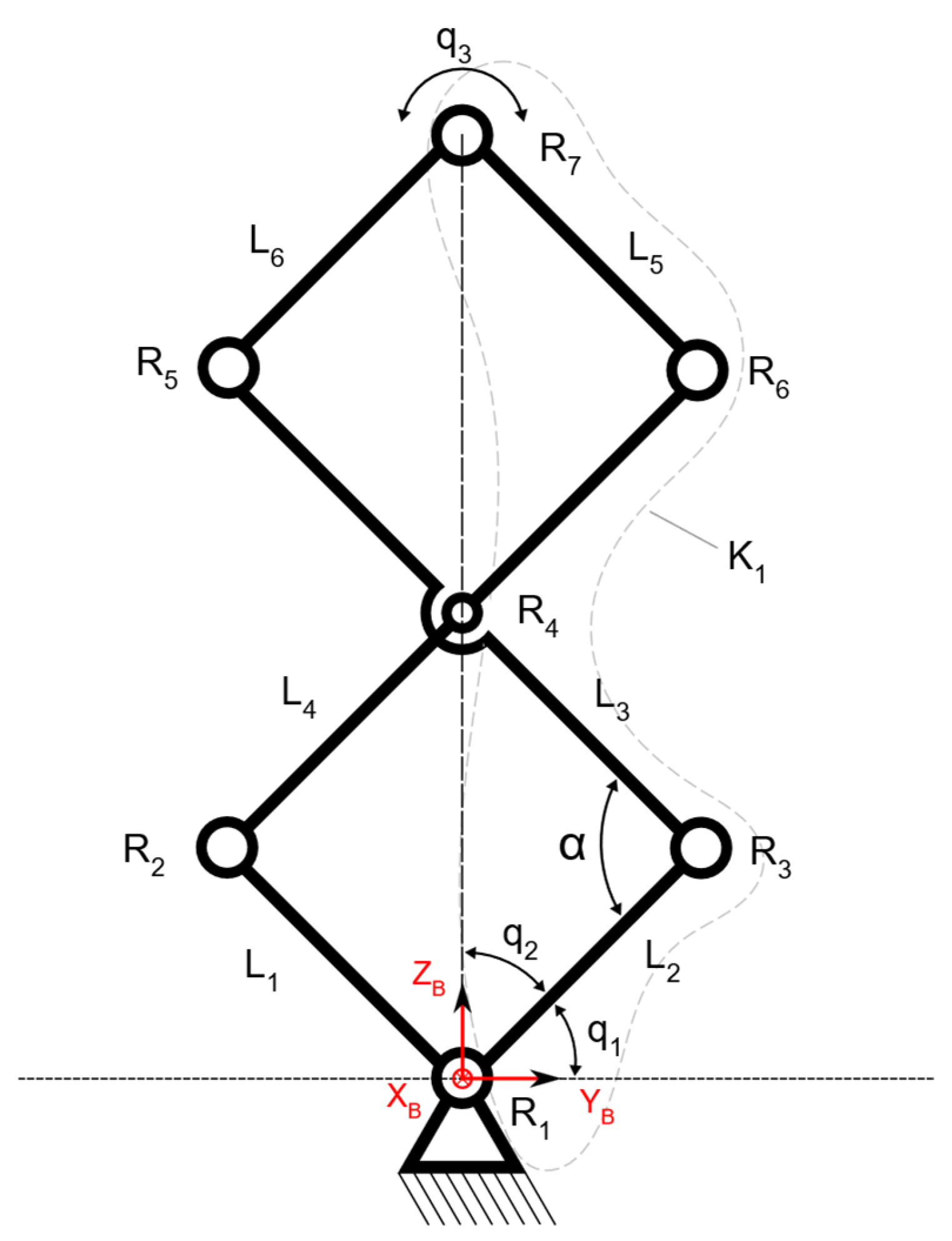
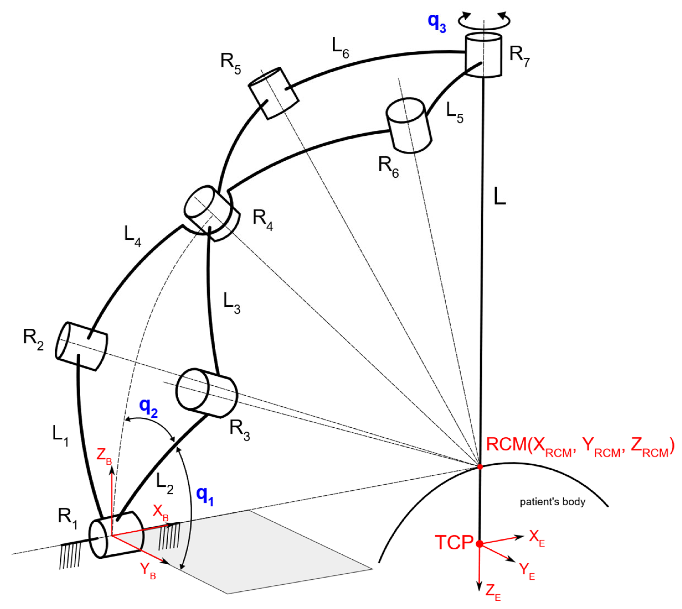
Figure 1 illustrates the spherical mechanism with six links connected through seven revolute joints, two active and five passive. The virtual axis of each revolute joint is oriented so that all axes meet in the center of the spherical mechanism, establishing a remote center of motion around which the structure rotates. The parameters
q1,
q2 and
q3 represent the active joints.
When both links L1 and L2 rotate synchronously in opposite directions, the spherical mechanism extends or retracts. As the angle between links L1 and L2 shrinks, the same motion is transmitted to links L5 and L6 through L3 and L4, and vice versa. When both links L1 and L2 rotate synchronously in the same direction with the same angle, the entire mechanism rotates around the base XB axis. More specifically, if the angle between links L1 and L2 remains constant, the entire mechanism can rotate around the base axis XB. Based on this, a more simplified method of control was devised, where the two actuators are decoupled: one specifically controls the extension and retraction of the arm, while the other controls the rotation of the entire arm around the XB base axis, essentially eliminating any form of dependency between q1 and q2.
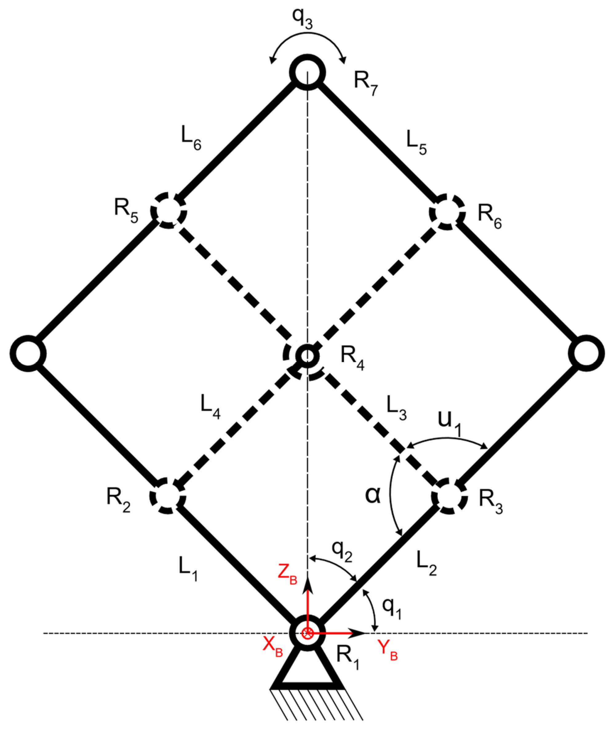
To simplify the process of computing the kinematic equations, the entire structure can be projected from three-dimensional space onto a two-dimensional plane by extending the RCM point to infinity and “unwrapping” the spherical mechanism, thereby obtaining a more intuitive topology that resembles a parallelogram mechanism with scissor mounting, or a jack mechanism, as illustrated by the kinematic scheme in
Figure 2.
This is useful in determining the relationships between the angles of each link. From here, the mechanism can be further enhanced by virtually extending the
L1 and
L2 links until they meet links
L5 and
L6 at two different points, marked by joints
R8 and
R9, as illustrated in
Figure 3. This configuration, along with many others, can function properly as long as the links themselves remain parallel to each other, maintaining the form of a parallelogram mechanism.
For kinematic modeling, the standard 3 × 3 rotation matrices around the X, Y and Z axes by angle γ are denoted RX(γ), RY(γ), and RZ(γ). Each rotation matrix belongs to the special orthogonal group SO(3), which represents all possible rotations in three-dimensional space around an origin, expressed in 3 × 3 orthogonal matrices with a determinant of +1, preserving orientation.
3.1.1. Symmetric Modeling of the Spherical Chain
Given the symmetrical nature of the mechanism’s architecture, it is sufficient to study only the
K1 kinematic chain for kinematic modeling, which represents one lateral half of the entire mechanism. The mapping between the reference frame and the end-effector frame is described through the following transformation:
where
α1 = 15° is the geometric angle of separation between adjacent joint axes with respect to the RCM,
q1 and
q2 are the active joint coordinates and
u1 is the passive joint coordinate of the studied chain. The
OX local axis of the frame attached to joint
R1 describes the unit vector associated with the axis of the surgical instrument:
3.1.2. RCM-Orientation Parametrization for Joystick Teleoperation
For the 3-axis joystick, a simpler RCM-orientation parametrization in terms of three orientation angles (
ψ,
θ,
φ) describes the rotation of the instrument axis around the RCM:
When the mechanism is used purely for orientation, the insertion length
L is decoupled from the other motions, and the roll angle
φ is driven exclusively by
q3, leading to the compact forward and inverse forms:
with associated velocity Jacobians
J3 and
J4.
3.1.3. Mobility, Jacobian and Singularity Analysis
The mobility of the spherical linkage is established before the differential analysis. The mechanism comprises six moving links interconnected by seven revolute joints whose axes all intersect at the remote center of motion, so that every admissible motion belongs to the rotation group SO(3). For the extension–retraction loop, which has the topology of a double spherical parallelogram, the spherical form of the Chebyshev–Grübler–Kutzbach criterion yields a single internal degree of freedom, driven by the active joint
q2, as shown in Equation (10). The base-axis rotation
q1 and the end-effector roll
q3 contribute two further actuated degrees of freedom. The instrument is therefore positioned with three actuated degrees of freedom: two degrees of freedom orient the instrument axis about the remote center of motion, described by the angles
ψ and
θ, while the third degree of freedom defines the roll angle
φ, with
φ ≡
q3.
Substituting the rotation operators of Equation (1) into the orientation parametrization of Equations (6) and (7) and eliminating the passive coordinate u
1 through the loop-closure constraint, yields the explicit closed-form forward map of Equation (8). In this map,
φ =
q3 holds exactly, the elevation angle
θ depends only on the base-rotation coordinate
q1, and the azimuth
ψ depends on both active coordinates
q1 and
q2. The corresponding inverse map is given in Equation (9); because
θ(
q1) is strictly monotonic over the operating range, with
∂θ/
∂q1 > 0 for |
q1| < 90°,
q1 is recovered uniquely from
θ, after which
q2 follows from
ψ in closed form, as shown in
Supplementary Materials. These explicit expressions replace the general placeholder forms
f1…
f3 and
g1…
g3 used in the definition of the model and make the decoupling structure precise: the roll axis is exactly decoupled, the elevation
θ is governed by a single joint, whereas the azimuth
ψ remains kinematically coupled to both active joints.
Differentiating the forward map with respect to the actuated coordinates gives the velocity Jacobian
J3, which relates the joint rates to the rates of the instrument-orientation parameters, namely (
,
,
) ↦ (
,
,
). Because
φ =
q3 and
θ is independent of
q2,
J3 is lower-block-triangular, with the closed-form entries given in Equation (11). In particular,
∂θ/
∂q1 admits the compact form shown in Equation (11), while the azimuth row couples both active joints through
∂ψ/
∂q1 and
∂ψ/
∂q2.
The determinant of the orientation Jacobian factorizes as det
J3 = −(
∂ψ/
∂q2)(
∂θ/
∂q1), so the mechanism is singular only when one of these two scalar factors vanishes, as shown in Equation (12). The first factor gives
∂θ/
∂q1 = 0 ⇔ cos
q1 = 0, i.e.,
q1 = ±90°, which corresponds to a boundary singularity at the extreme base-link configuration. The second factor gives
∂ψ/
∂q2 = 0 ⇔ cos
q2 = 2 sin
q1 sin(
q1 +
q2) cos
2 α1, which defines the extension-retraction singular locus. With the design value
α1 = 15°, both singularity conditions occur only near the boundary of the reachable region; therefore, the central operating workspace remains singularity-free.
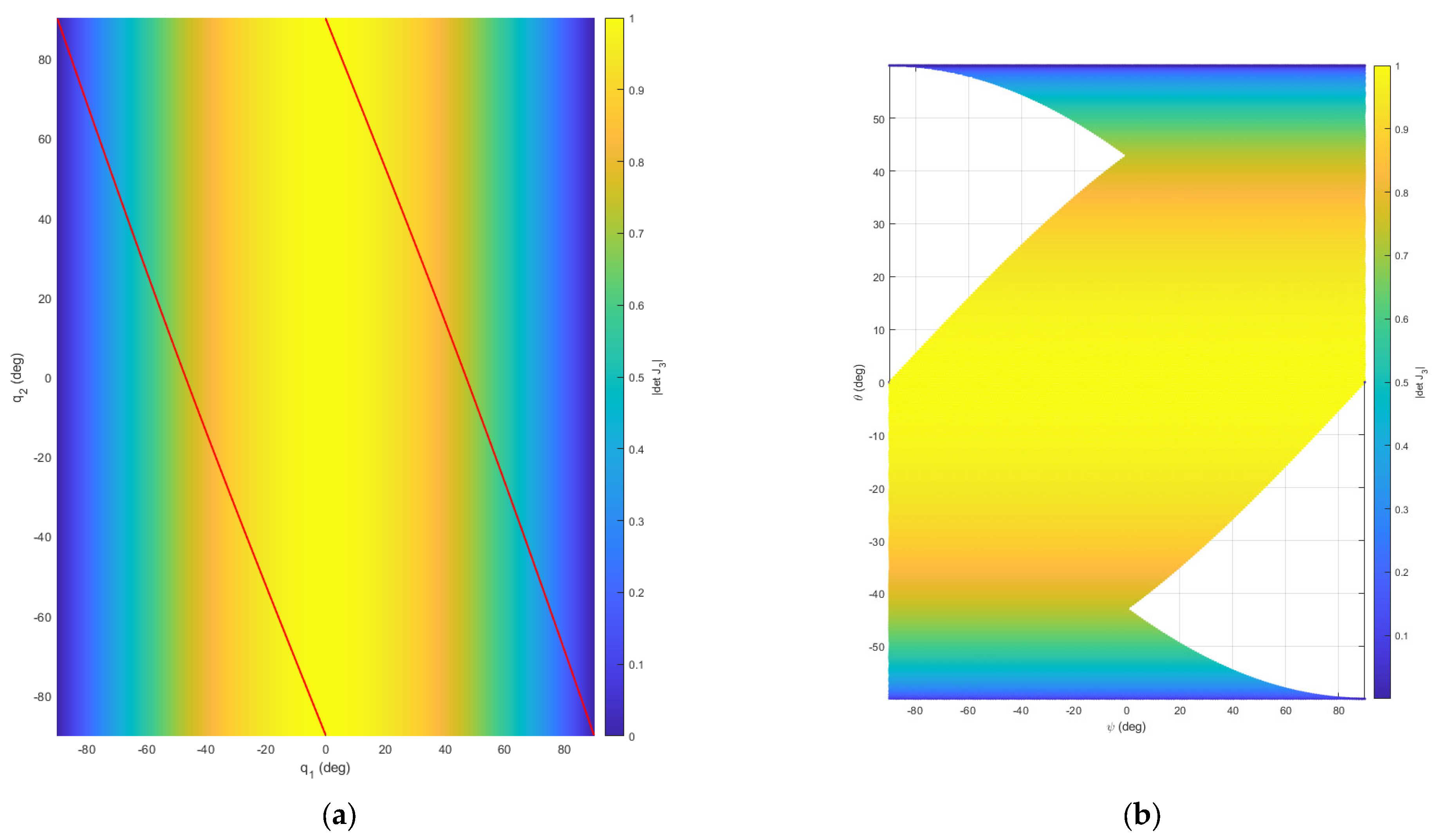
Figure 4 maps the absolute value of the determinant of the orientation Jacobian
J3 over the actuated joint space (
Figure 4a) and the corresponding reachable instrument-axis orientations
ψ and
θ (
Figure 4b), both evaluated for
α1 = 15°. The red curve in
Figure 4a marks the extension and retraction singular locus. Away from this locus and from the boundary configurations, the manipulability index |det
J3| remains above zero across the selected operating range, confirming smooth and well-conditioned orientation control in the central workspace. Representative forward-kinematics values illustrate this behavior: (
q1,
q2) = (20°, 10°) gives (
ψ,
θ) = (47.50°, 19.69°) with |det
J3| = 0.954; (30°, −15°) gives (
ψ,
θ) = (41.57°, 28.96°) with |det
J3| = 0.894; and (−25°, 20°) gives (
ψ,
θ) = (−26.99°, −24.40°) with |det
J3| = 0.927. These configurations are all located away from singular configurations.
3.2. Robot Structure Design and CAD Modeling
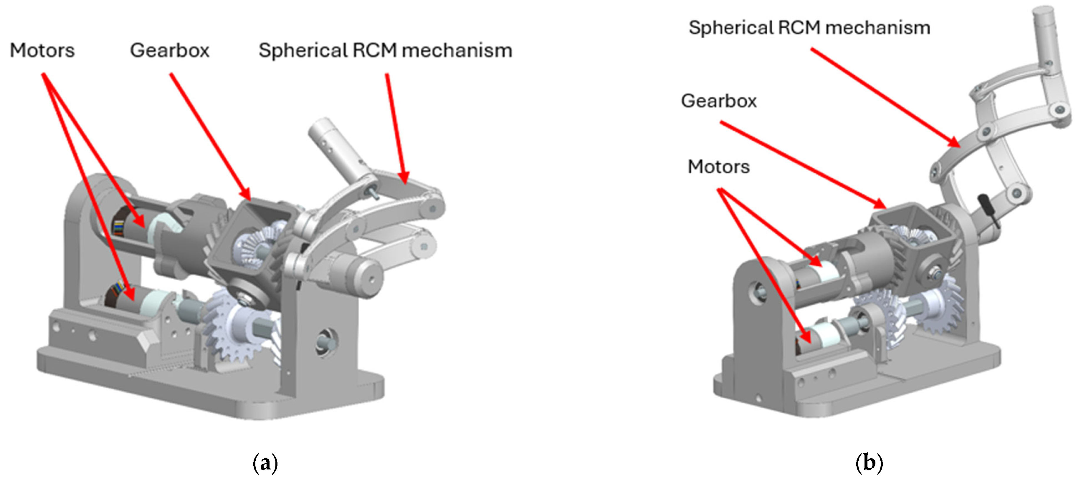
The complete robotic structure was designed in Siemens NX 2506 (Siemens, Plano, TX, USA), with the objective of integrating the spherical RCM mechanism, the contra-rotating gearbox, the actuator housings, the supporting bearings and the base frame into a compact proof-of-concept assembly. The design was developed around the requirement that the extension and retraction motion of the spherical mechanism and the rotation around the base axis should be driven by independent actuator chains.
Figure 5 presents the overall mechanical structure in two representative configurations: folded (a) and unfolded (b).
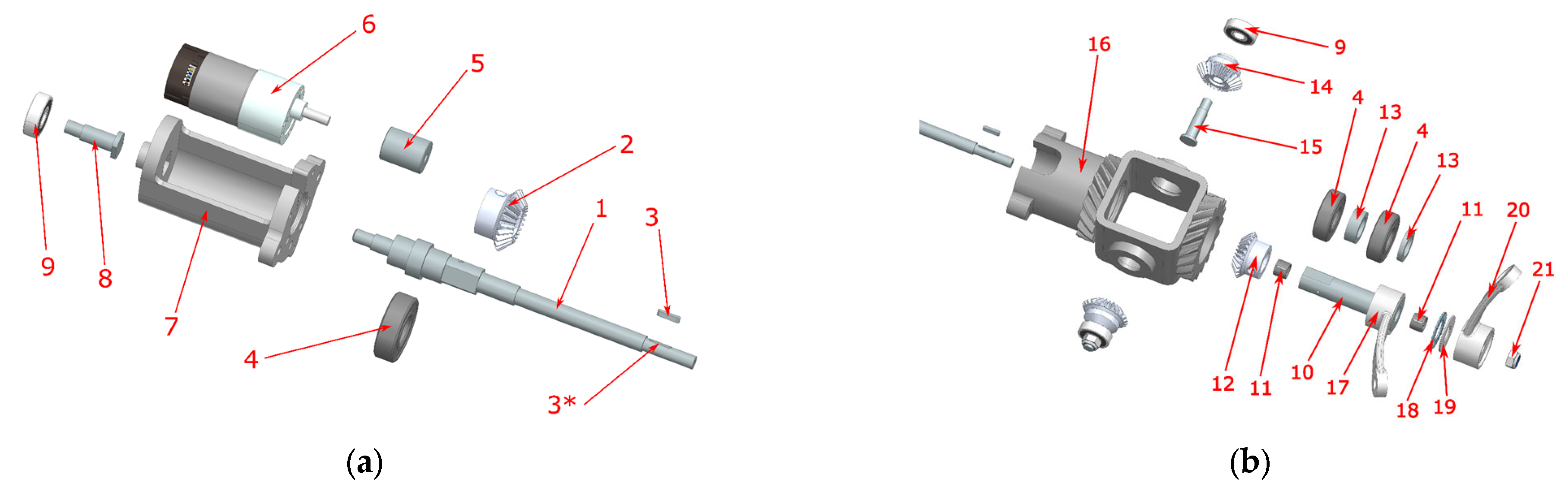
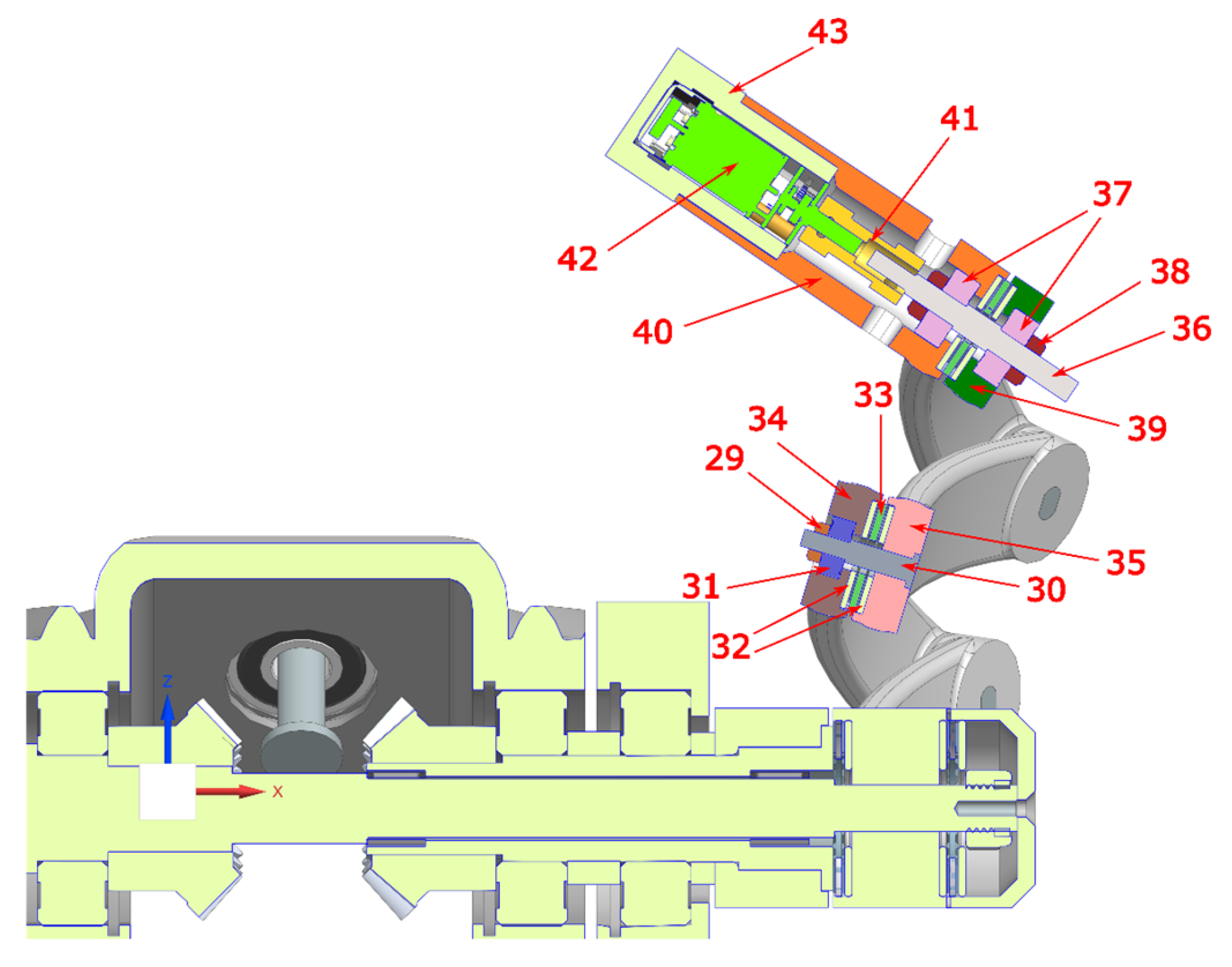
Figure 6 illustrates an exploded view of the components integrated into the contra-rotating gearbox, while
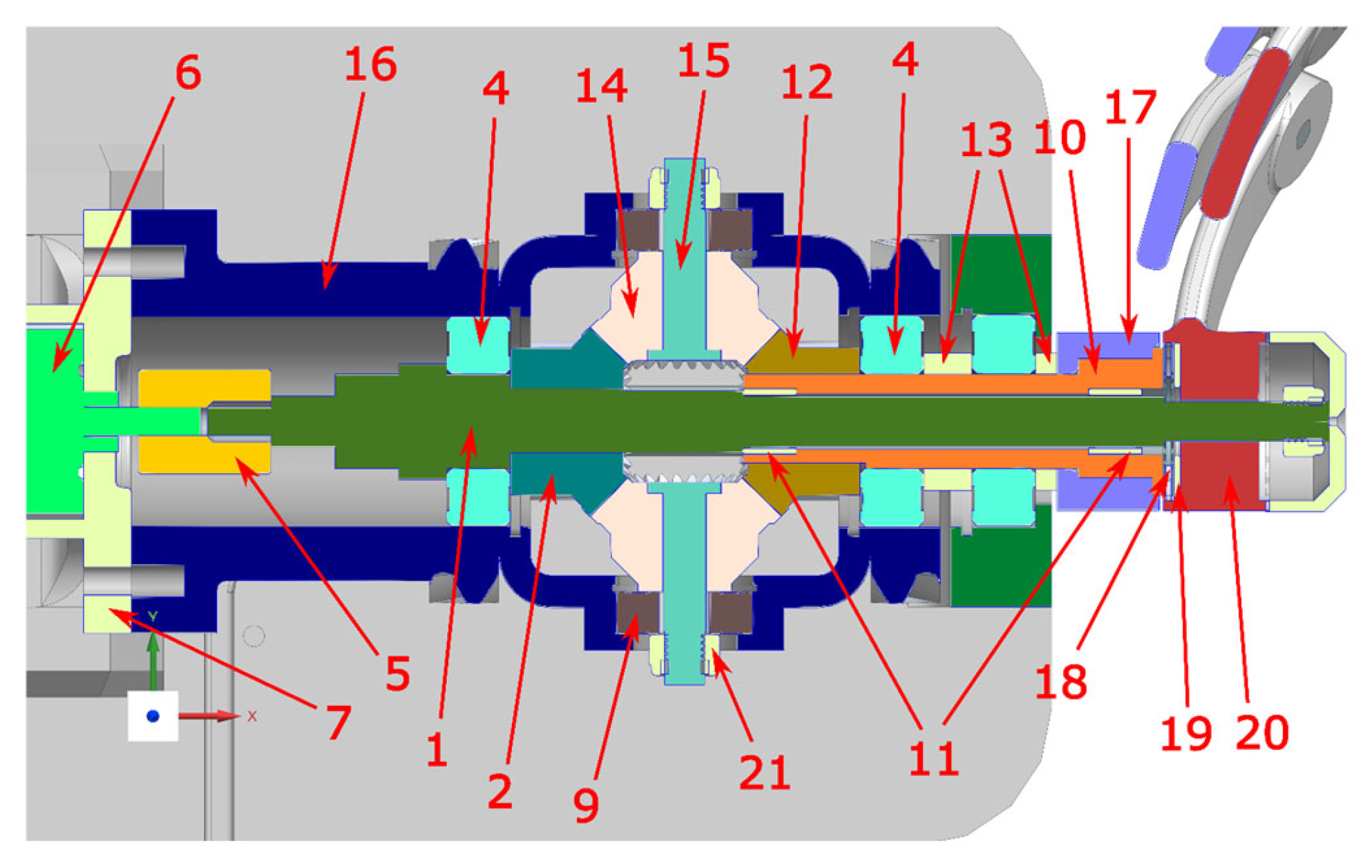
Figure 7 presents a sectioned view showing how these components mesh together, with each component referenced in
Table 3.
The key design challenge was the actuation of the two base links, L1 and L2, during extension and retraction. This motion requires the two links to rotate synchronously in opposite directions. To achieve this mechanically, a contra-rotating gearbox was developed and integrated at the base of the spherical mechanism. The gearbox converts one input rotation into two coaxial output rotations of equal magnitude and opposite direction, allowing the spherical mechanism to extend and retract without requiring cable transmissions or two electronically synchronized motors.
The main components of the contra-rotating gearbox are illustrated in
Figure 6a,b. The input shaft also acts as the first output shaft and drives the input bevel gear. This gear meshes with two satellite bevel gears mounted symmetrically inside the gearbox housing. The satellite gears transmit motion to the output bevel gear, which drives the second coaxial output shaft in the opposite direction. In this configuration, the gearbox has a 1:1 transmission ratio, which was sufficient for proof-of-concept validation, although it limits torque amplification and motion resolution.
The gearbox housing was designed to accommodate the input shaft, the second output shaft, the bevel gear pair, the satellite gears and the supporting bearings. The main shafts are supported by 6203-2RS radial ball bearings, while the satellite bevel gear shafts are supported by 6000-2RS radial ball bearings. The first output shaft includes a keyway interface for coupling with link L1, while the second output shaft is hollow, allowing the first shaft to pass through it concentrically. To reduce friction between the two coaxial shafts, K10 × 13 × 10 radial needle roller cages were placed inside the second output shaft.
Figure 7 illustrates the sectioned view of the contra-rotating gearbox and clarifies the internal meshing between the input bevel gear, the satellite bevel gears and the output bevel gear.
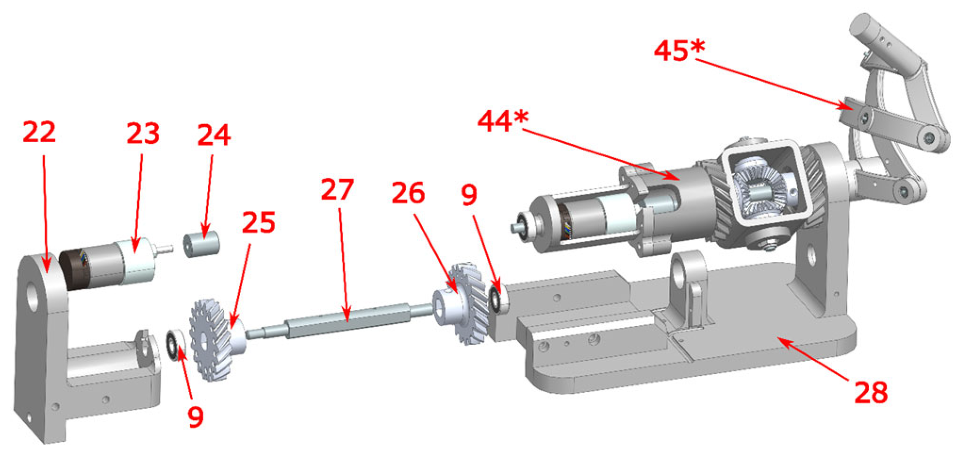
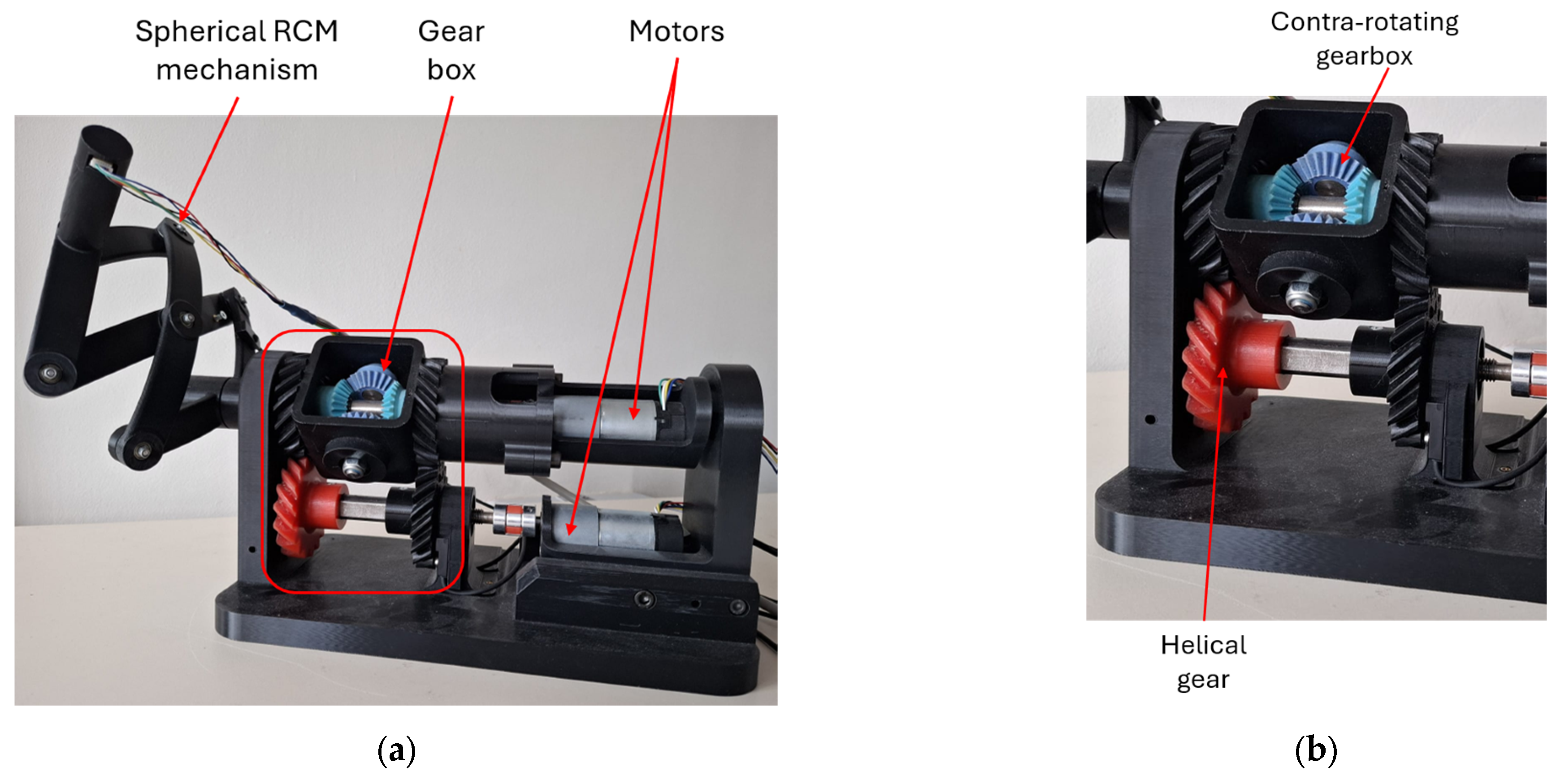
The rotation of the entire spherical mechanism around the base axis is driven separately from the extension and retraction motion. For this purpose, the contra-rotating gearbox assembly is mounted in the base frame and rotated by a second actuator through a helical gear transmission. The q1 actuator drives a helical gear shaft located below the contra-rotating gearbox, while the corresponding driven helical gears are integrated into the gearbox housing. As a result, the entire gearbox assembly can rotate around the base axis without affecting the opposed rotation of links L1 and L2.
The structural elements associated with this base-axis rotation are presented in
Figure 8, including the
q1 actuator,
q2 actuator, actuator housing, helical gear pair, elastic coupler, bearing blocks and robot base frame. The inner bearing block also supports the inductive sensors used for homing and limiting the
q1 motion. The nearby helical gear includes fourteen radial holes spaced at 25° intervals, allowing screws to be positioned as adjustable mechanical references for the sensor-based angular limits.
The spherical RCM mechanism consists of links L1 to L6 connected through active and passive revolute joints. The axes of the joints are arranged with a 15° angular separation with respect to the RCM point, according to the kinematic architecture described previously. The q2 homing and end-stop function is implemented through an inductive sensor mounted on link L2, which detects a metallic screw placed on link L3 when the mechanism approaches its retracted limit.
Figure 9 presents a sectioned view of the active and passive joints of the spherical mechanism. The passive revolute joints are assembled around custom aluminum shafts. Axial play is reduced using AXK0619 needle roller cages and AS0619 needle roller washers (SKF, Gothenburg, Sweden), while radial stability is provided by 623-ZZ radial ball bearings (NSK Ltd., Tokyo, Japan). The active end-effector joint
R7, corresponding to
q3, integrates the
q3 actuator directly inside the link housing. The actuator drives the end-effector active joint shaft through a rigid coupler, while two 624-2RS radial ball bearings stabilize the shaft. The outer end of this shaft is designed to allow the attachment of an endoscopic camera or another slender instrument.
After the CAD design was completed, the structural components were exported as STL files for additive manufacturing. The robot links, base frame, motor housings and gearbox housings were manufactured using a Stratasys Fortus 380MC system, while the bevel gears were produced using a Stratasys J5 MediJet printer (Stratasys, Eden Prairie, MN, USA) to obtain improved resolution for the gear teeth. The shafts used in the gearbox and revolute joints were manufactured separately based on technical drawings. The final assembly, illustrated in
Figure 10, combined the printed structural components, machined shafts, bearings, actuators and sensors into the complete proof-of-concept robotic mechanism.
3.3. Embedded Hardware and Control Architecture
The mechanical prototype was integrated with a custom embedded hardware and control architecture designed to actuate the three motorized axes, acquire position and limit feedback, communicate with the master console and support the teleoperation workflow used during the phantom-torso experiments. Since the objective of the present work is to report the complete technological demonstrator rather than the detailed electrical design of each circuit block, the electronic subsystem is presented at a functional level. The complete schematic sheets of the microcontroller core, motor drivers, sensor interface and USB–USART communication circuit can be provided as
Supplementary Material.
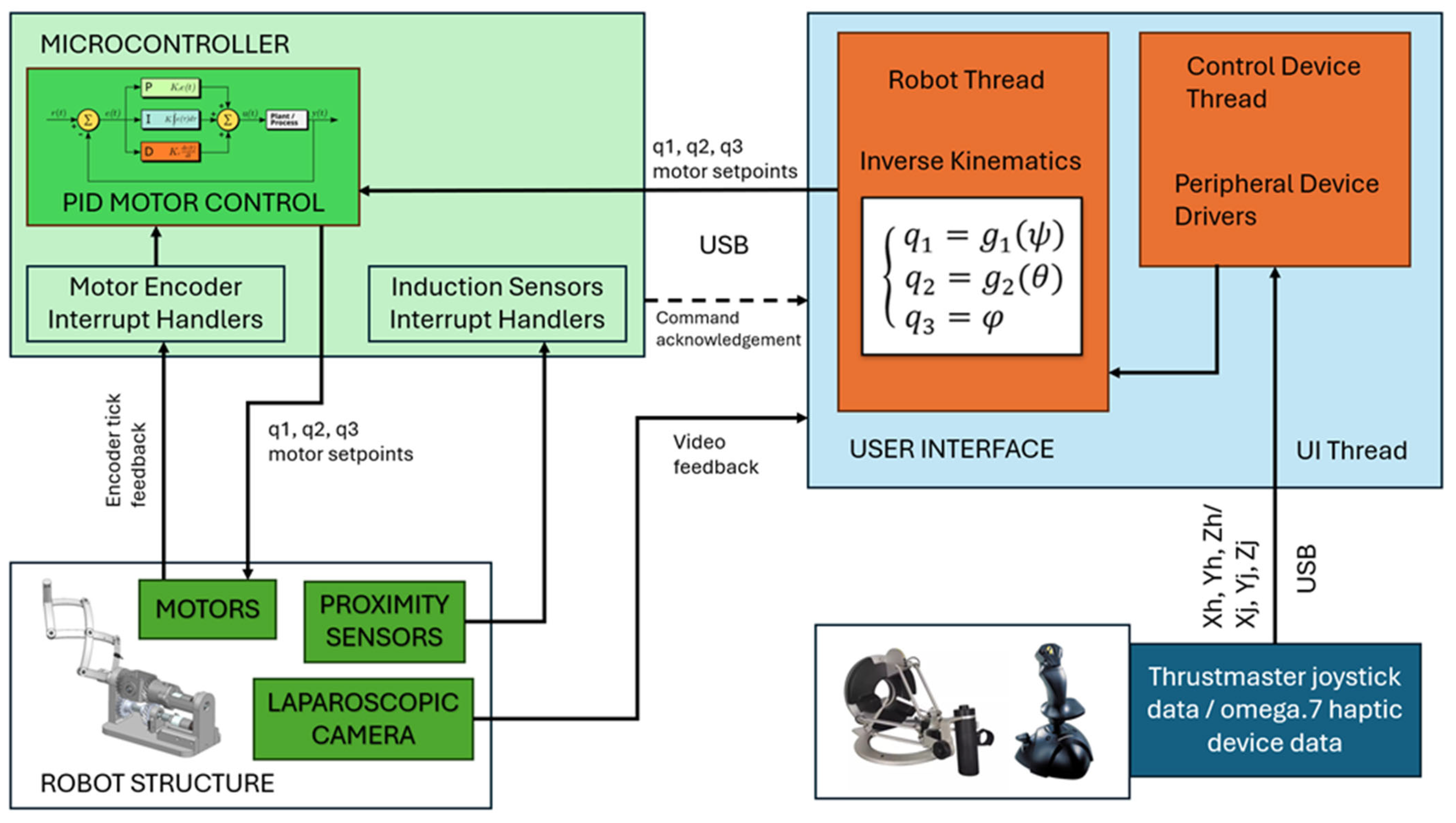
Figure 11 presents the system-level electrical and control architecture of the robotic demonstrator. The host computer runs the graphical user interface, processes the commands received from the selected input device and sends the corresponding joint references to the embedded controller through a USB–USART communication link. Two master devices were integrated: the Force Dimension omega.7 haptic device (Force Dimension, Nyon, Switzerland), used for Cartesian-style teleoperation, and a 3-axis joystick (Guillemot Corporation, Carentoir, France), used for direct RCM-orientation control. The same graphical interface also displays the video stream acquired from the USB endoscopic camera mounted at the end-effector.
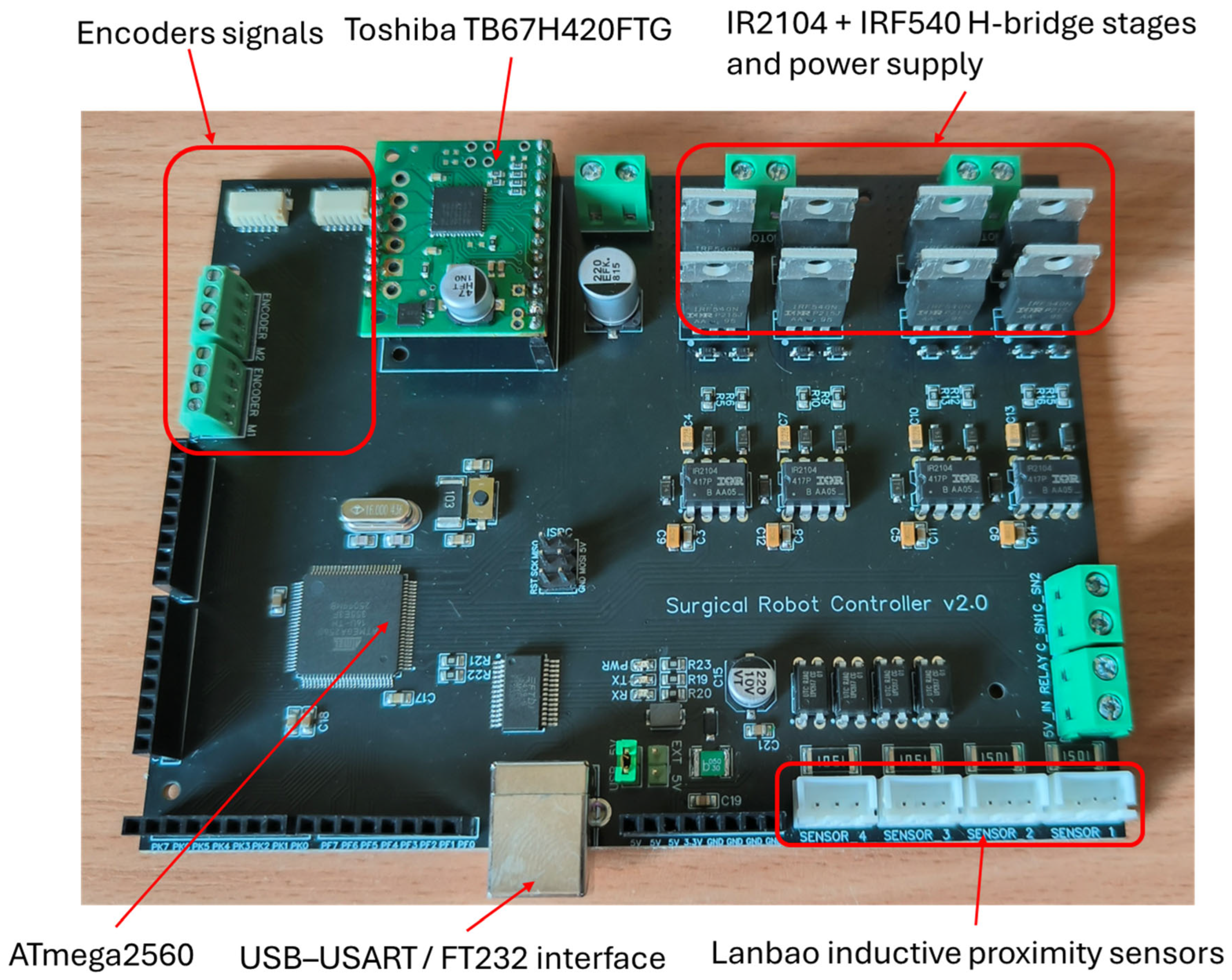
The custom controller was implemented as a four-layer printed circuit board based on an ATmega2560 microcontroller (Microchip Technology Inc., Chandler, AZ, USA). The board integrates the main subsystems required by the prototype, including motor-driver interfaces, encoder inputs, inductive end-stop inputs, analog current acquisition and USB-USART communication with the host computer. The embedded controller executes the low-level motor-control tasks locally, while the master console remains responsible for teleoperation, inverse kinematics, user interaction and visual feedback.
The main axes of the robot,
q1 and
q2, are driven through H-bridge motor-driver stages based on IR2104 (Infineon Technologies AG, Neubiberg, Germany) high- and low-side gate drivers and IRF540 N-channel MOSFETs (Infineon Technologies AG, Neubiberg, Germany). These stages allow bidirectional control of the brushed DC gearmotors through PWM and direction commands generated by the microcontroller. The third axis,
q3, which actuates the end-effector rotation, is driven by a Toshiba TB67H420FTG (Toshiba Electronic Devices & Storage Corporation, Tokyo, Japan) [
43] auxiliary motor driver. Position feedback is provided by Hall-effect quadrature encoders, while homing and end-stop detection are implemented using Lanbao inductive proximity sensors (Shanghai Lanbao Sensing Technology Co., Ltd., Shanghai, China). Current feedback is acquired using ACS712 (Allegro MicroSystems, LLC, Manchester, NH, USA) [
43] Hall-effect current sensors, allowing abnormal motor-current conditions to be detected during operation.
The assembled controller board is shown in
Figure 12. The board provided the hardware interface between the master console and the robotic mechanism, integrating the microcontroller, motor-driver electronics, sensor-conditioning elements and communication interface into a single compact platform. During the experiments, the controller enabled closed-loop position control of the three actuated axes, homing using the inductive sensors and basic protection through current monitoring.
3.4. Embedded Firmware and Master-Console Interface
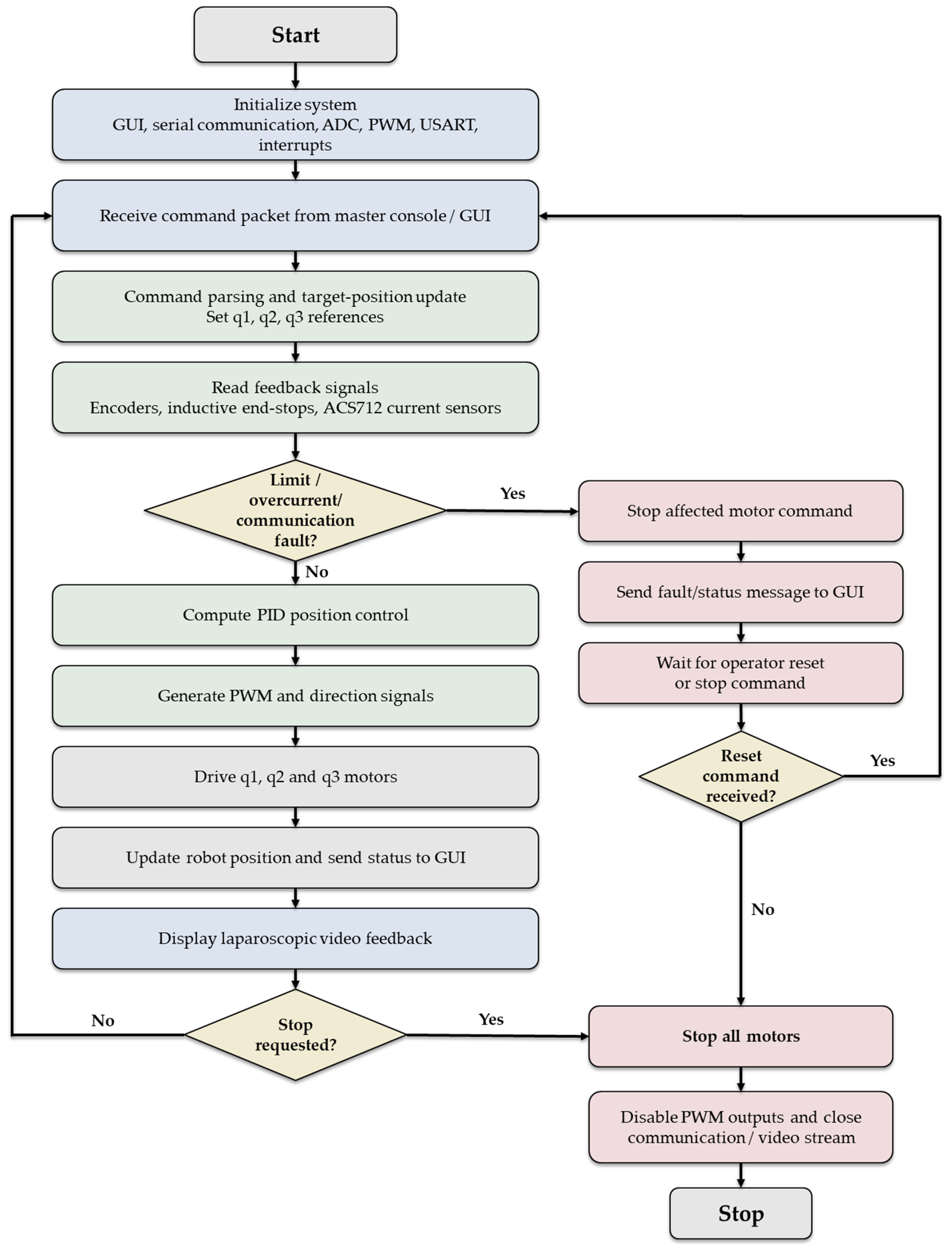
The embedded firmware and the master-console software were developed to connect the mechanical prototype, the custom controller board and the operator interface into a functional teleoperated robot, as illustrated in
Figure 13. The firmware was implemented in C23 using a bare-metal programming approach on the ATmega2560 microcontroller (Microchip Technology Inc., Chandler, AZ, USA). This approach was selected to allow direct control of the microcontroller peripherals required for real-time operation, including PWM generation, USART communication, ADC acquisition, timer configuration and external interrupt handling.
The firmware was organized into modular software blocks corresponding to the main embedded functions of the system. The main module coordinates the control loop and processes the commands received from the host computer. The configuration module centralizes the hardware definitions and timing parameters. The USART module manages serial communication with the master console. The sensor module handles ADC acquisition for the current sensors and configures the external interrupts used for encoder and end-stop feedback. The motor-control module generates the direction and PWM commands required to drive the actuators. This modular organization simplifies debugging and separates communication, sensing and motor-control tasks.
During a surgical procedure, the graphical interface sends target-position commands to the embedded controller through the USB-USART link. The controller reads the encoder counters, verifies the inductive end-stop states, samples the ACS712 [
44] current sensors and computes the motor commands using a position-based PID controller. The control output determines both the rotation direction and the PWM duty cycle applied to each motor driver. Current monitoring is used as a basic protection layer: if abnormal motor current is detected, the corresponding motor command can be stopped to prevent continued motion against an obstacle or mechanical limit.
To address the motion resolution constraints imposed by the 1:1 differential gearbox ratio and the inherent non-linearities of the 3D-printed gearing, an AI-based control upgrade path is envisioned for the platform. Instead of relying solely on static PID coefficients, an Adaptive Neuro-Fuzzy Inference System (ANFIS) or a Reinforcement Learning (RL) auto-tuning framework can be integrated. By utilizing the real-time motor current feedback from the ACS712 sensors alongside encoder telemetry, such an intelligent controller can dynamically adapt the PWM duty cycles to counteract varying frictional resistances and torque drops in mechanically unfavorable orientations, ensuring smoother trajectory tracking around the RCM.
The master-console application was developed in C++/CLI (Microsoft Visual Studio 2022, version 17.12, Microsoft Corporation, Redmond, WA, USA) using Windows Forms .NET 10.0. Its role is to provide the operator with a single interface for selecting the communication port, connecting the robot, selecting the active peripheral control device, starting the homing routine, engaging teleoperation and displaying the endoscopic video stream. The GUI also performs higher-level motion processing: it acquires data from the selected master device, applies the corresponding kinematic mapping and transmits the resulting motor references to the embedded controller.
Two teleoperation modes were implemented. In the haptic-device mode, the Force Dimension omega.7 (Force Dimension, Nyon, Switzerland) device is used to generate Cartesian-style commands that are converted into joint references through the inverse kinematic model. In the joystick mode, the 3-axis joystick is used for RCM-orientation control, where the joystick axes directly command the orientation of the endoscopic camera around the remote center of motion. The joystick-based mode is particularly suitable for camera-orientation tasks and was used during the phantom-torso validation.
The video feedback subsystem was implemented using OpenCV 4.13.0. The USB endoscopic camera mounted at the end-effector provides the image stream, which is displayed in the graphical interface during teleoperation.
Furthermore, the OpenCV-based visual pipeline serves as the foundation for an intelligent computer vision subsystem. By deploying a lightweight deep learning object detection network on the host computer, the system can automatically segment and track the internal visual markers in real time. This AI-driven feature extraction transforms the camera from a passive feedback tool into an active component of a closed-loop visual servoing architecture, capable of calculating alignment errors and generating autonomous corrective commands to keep targeted features centered without continuous manual joystick adjustments.
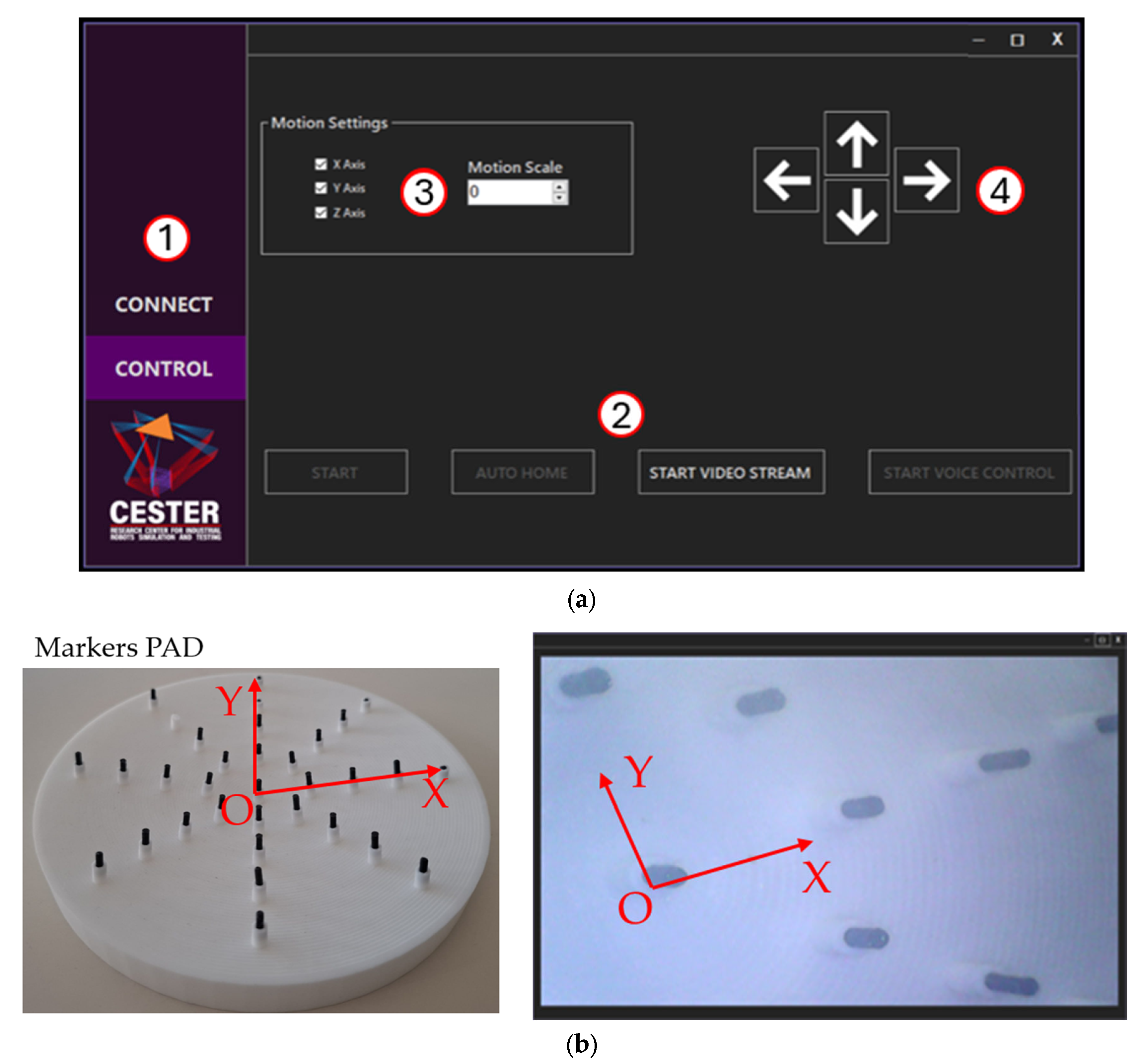
The user interface was designed to be easy to comprehend, having two main tabs, namely the connection and control tabs, where important functionalities are located.
Figure 14 a below illustrates these controls as follows: (1) Main tab selection menu; (2) Button menu for robot teleoperation start/stop, robot homing, camera feedback start/stop; (3) Motion setting group, with three checkboxes corresponding to each axis of the joystick/haptic device and a numeric field to set the motion increment; and (4) Incremental control group, comprising four buttons for the X and Y axis of teleoperation.
Figure 14b illustrates the marker pad.
3.5. Phantom Torso Experimental Setup
The surgical robot was evaluated through a qualitative phantom-torso experiment intended to verify the functional feasibility of the spherical RCM mechanism for endoscopic camera-orientation tasks. The objective of this experiment was to determine whether the assembled system could be teleoperated around the remote center-of-motion point while providing useful visual feedback from inside a constrained, torso-like workspace.
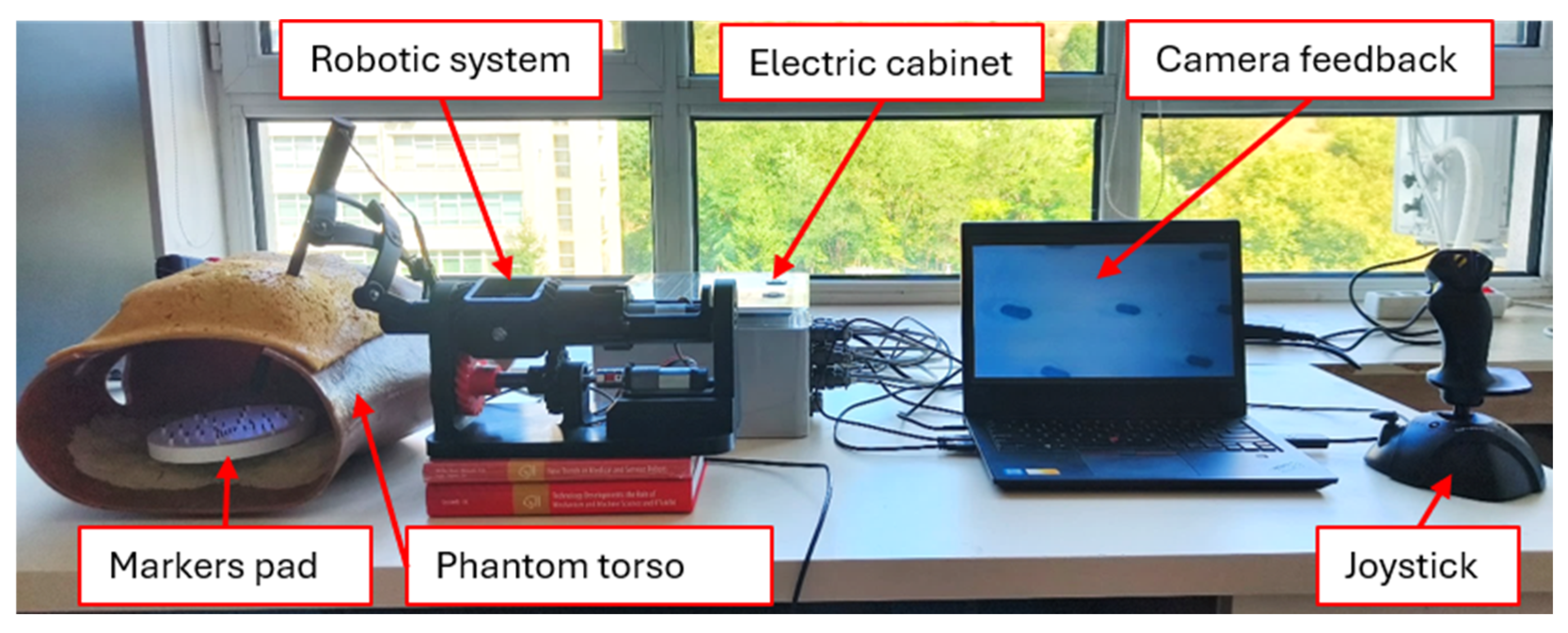
The experimental setup presented in
Figure 15 consisted of a phantom torso, a 3D-printed custom pad with an array of markers, a custom 3D-printed endoscopic camera, and the robot itself. The phantom torso was used to provide an anatomical reference similar to a minimally invasive surgical environment, constraining the range of motion of the mechanism to a limited workspace. The marker pad was modeled to have slightly concave geometry to allow the endoscopic camera to roughly center each marker visually on the graphical user interface video stream.
The internal marker pad was placed inside the phantom torso in a position where the camera could visualize the individual markers during the orientation of the spherical mechanism. The pad was designed with slightly concave geometry to facilitate visual centering of the markers in the camera image. During the experiment, the operator attempted to orient the endoscopic camera so that each marker appeared successively in the graphical interface video stream. This setup made it possible to test the practical interaction between the RCM mechanism, the teleoperation interface, the embedded controller and the video-feedback subsystem.
Before the experiment, the robot was powered on and connected to the master console through the serial interface. The automatic homing routine was then executed, using the inductive end-stop sensors to define the reference positions of the actuated axes. After homing, the endoscopic video stream was started in the graphical user interface. The joystick-based RCM-orientation mode was used as the main teleoperation method because it provided a direct mapping between operator input and camera orientation around the remote center of motion. The Force Dimension omega.7 haptic device remained available as an alternative input device for Cartesian-style control, but the phantom-torso evaluation focused primarily on camera orientation using the joystick.
4. Results
The robot was manufactured, assembled and integrated into a functional teleoperated platform. The final system included the spherical RCM mechanism, the contra-rotating gearbox, the helical-gear transmission for base-axis rotation, the end-effector rotation axis, the inductive end-stop sensors, the custom four-layer controller board, the embedded firmware, the master-console graphical interface and the custom USB endoscopic camera.
The mechanical structure was able to reach both extended and retracted configurations during laboratory testing. The contra-rotating gearbox enabled the opposed rotation of the two base links during extension and retraction, while the second actuator chain rotated the gearbox assembly around the base axis. The end-effector actuator provided additional camera-orientation capability. The custom controller board enabled motor actuation, encoder-based feedback, inductive-sensor homing and current monitoring during operation.
The phantom-torso experiment confirmed that the system could be teleoperated. After the homing routine, the operator used the joystick-based RCM-orientation mode to move the endoscopic camera around the torso entry point. The camera was oriented from left to right and from a more extended configuration toward a more retracted configuration, while the internal marker pad was observed through the graphical interface.
The video feedback from the USB endoscopic camera was displayed successfully in the master-console interface. The operator was able to bring individual markers into the camera’s field of view and visually center them on the screen. This confirmed that the mechanical structure, embedded controller, joystick teleoperation and video-feedback subsystem could operate together during a representative laboratory task.
The experiment demonstrated that the proposed spherical RCM architecture can be used as a platform for endoscopic camera-orientation tasks. The robot responded to joystick commands and allowed the camera to be repositioned around the phantom-torso access point. The marker pad could be observed from several camera orientations, indicating that the proposed architecture provides a usable range of motion for qualitative visual targeting.
However, the evaluation also revealed several technical limitations. The first limitation was related to motion resolution. Because of the 1:1 ratio of the contra-rotating gearbox and the characteristics of DC motor transmission, small motor motions could produce relatively large visible changes in camera orientation. This made precise marker centering more difficult in some configurations.
The second limitation was related to the available actuation torque. In certain orientations, especially when the mechanism was positioned close to the phantom torso or when the configuration became mechanically less favorable, the motors had reduced ability to move the structure smoothly. This limitation is partly associated with the proof-of-concept nature of the 3D-printed gearbox and with the absence of a reduction stage for torque amplification.
The third limitation was observed in retracted configurations of the spherical mechanism. When the arm was retracted, the links formed a more compact semi-spherical shape, reducing the usable rotation around the base axis because of possible interference with the phantom torso. In contrast, when the mechanism was more extended, the available angular motion around the base axis increased.
The results of the tests are depicted in
Table 4.
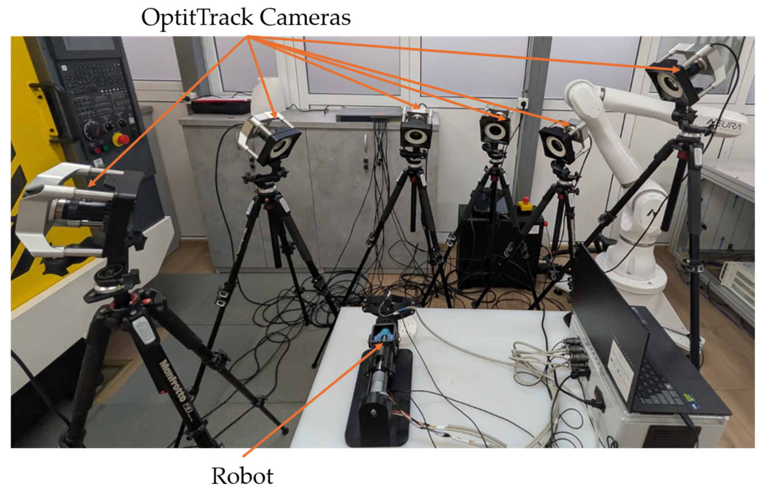
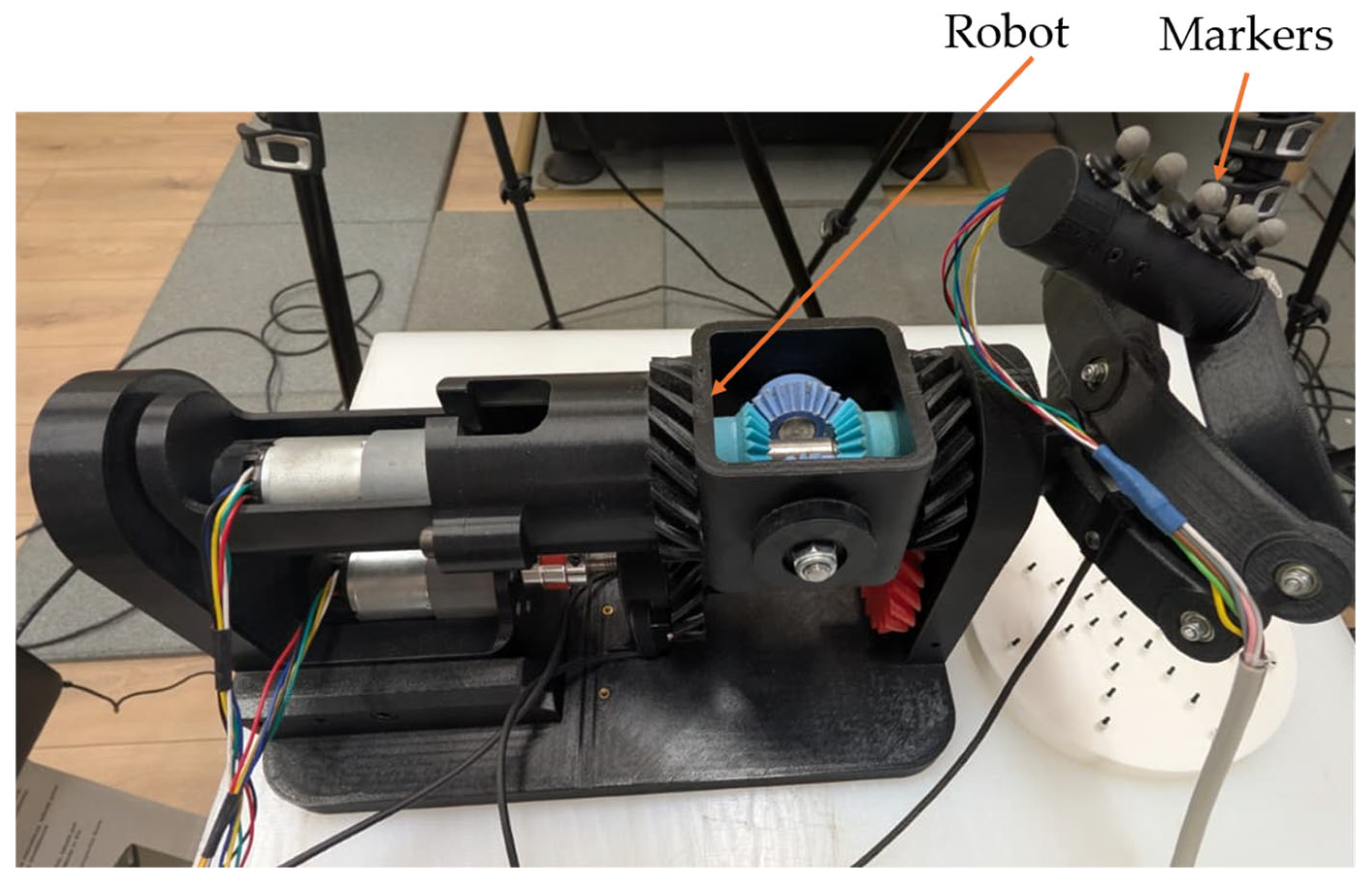
To complement the qualitative phantom-torso evaluation, the remote-center-of-motion accuracy was measured using an OptiTrack optical tracking system, as illustrated in
Figure 16.
Five retro-reflective markers were mounted collinearly on the external shaft of the instrument, as illustrated in
Figure 17, on the same rigid segment that transmits motion to the part passing through the trocar. The robot was commanded through an orientation sweep around the remote center of motion, while the three-dimensional marker trajectories were recorded.
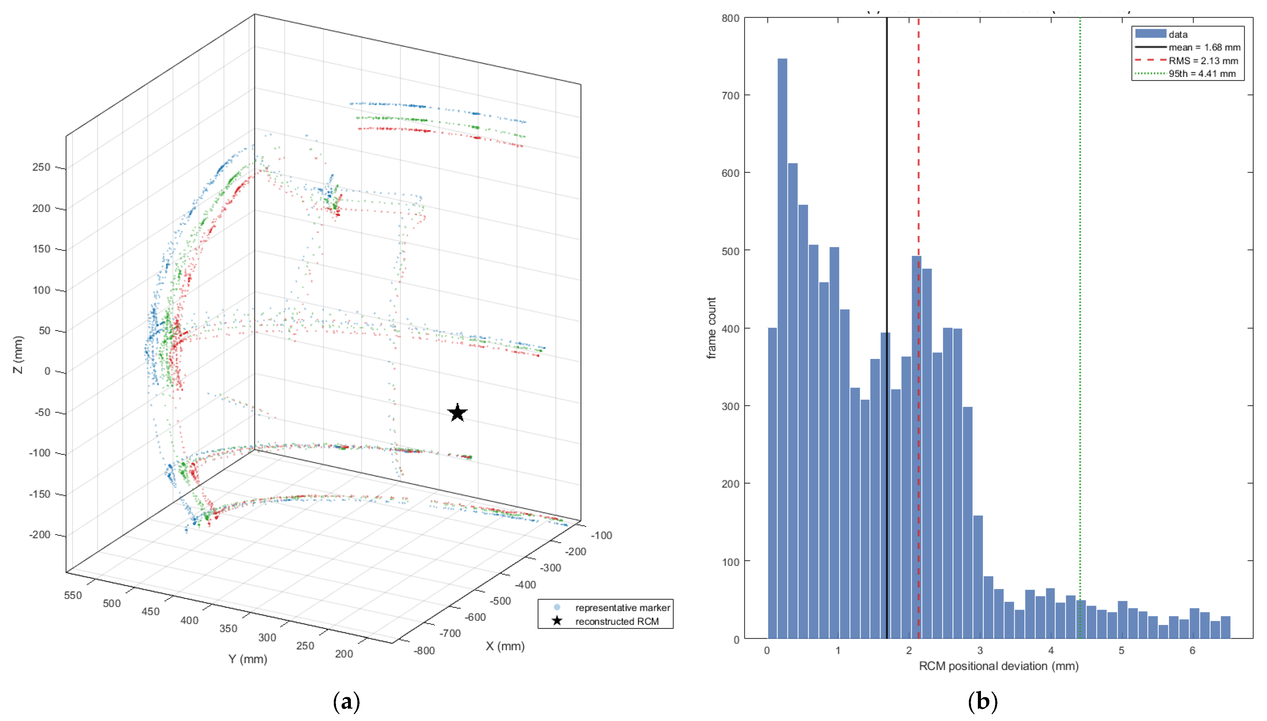
Because the five markers were mounted in series along the instrument shaft, the rigid-body orientation returned by the motion-capture software was not used directly. A collinear marker arrangement is poorly conditioned for estimating rotation about the shaft axis. Instead, the remote center of motion was reconstructed directly from the marker positions. During an ideal pivoting motion, each marker fixed on the shaft describes a spherical trajectory whose center coincides with the remote center of motion. Therefore, the remote center was estimated as the common center of the marker trajectories using a least-squares sphere-center fitting procedure.
The five markers mounted on the instrument shaft were used for the analysis. Other markers detected by the OptiTrack system were excluded, since they did not belong to the instrument marker set and produced inconsistent or intermittent trajectories. Frames affected by optical-tracking dropouts, marker swaps or residual outliers were removed before computing the final accuracy metrics. After this filtering step, 9915 valid frames were retained for the final RCM accuracy analysis. The outlier rejection applied a fixed per-frame threshold of approximately three times the RMS deviation (6.5 mm), corresponding to a 3σ criterion.
The reconstructed remote center of motion was located at approximately [−466, 200, −41] mm in the OptiTrack global coordinate frame. The measured RCM positional deviation had a mean value of 1.69 mm, a root-mean-square value of 2.13 mm, a median value of 1.51 mm and a 95th percentile of 4.39 mm. These results indicate that the proposed contra-rotating differential mechanism maintained the remote-center-of-motion constraint within approximately 2 mm RMS during the analyzed orientation sweep. The obtained values are close to the expected optical-tracking uncertainty of the marker cluster, suggesting that the reported deviation represents an upper bound on the actual mechanical RCM error of the proof-of-concept prototype.
Because the remote center was reconstructed by least-squares sphere fitting from five collinear markers, the reported RMS deviation combines the true mechanical wander of the pivot with the positional noise of the optical-tracking system and the reconstruction error of the ill-conditioned collinear geometry. It is therefore of the same order as the noise floor of the measurement chain and represents an upper bound on the mechanical RCM error rather than a sub-millimeter precision. Repeatability was not characterized in this proof-of-concept study, which was limited to a single continuous sweep. The planned protocol, executing the same commanded sweep N times under identical homing and reporting the standard deviation of the independently reconstructed center positions across repetitions, will be applied to the redesigned prototype.
Quantitative evaluation of remote-center-of-motion accuracy are presented in
Table 5 and
Figure 18.
5. Discussion
The present work demonstrates the development of a complete proof-of-concept robot based on a mechanically constrained spherical remote center-of-motion mechanism for minimally invasive surgical orientation tasks. Unlike purely conceptual mechanism studies, the proposed system integrates the mechanical structure, the contra-rotating gearbox, the custom embedded controller, the firmware, the graphical interface and the endoscopic video-feedback subsystem into a functional robot. The phantom-torso experiment showed that the mechanism can be teleoperated to orient an endoscopic camera inside a constrained workspace and to visualize internal markers through the graphical interface. The validation combines a qualitative phantom-torso demonstration with a quantitative optical-tracking measurement of RCM accuracy and should be interpreted as an initial feasibility demonstration rather than a complete performance assessment or clinical validation.
5.1. Relevance of the Mechanically Constrained Spherical RCM Architecture
The principal advantage of mechanically constrained RCM mechanisms is that the pivoting behavior is imposed by the geometry of the mechanism itself. In the context of minimally invasive surgery, this is important because the instrument or camera shaft must rotate around the trocar region without generating excessive lateral displacement at the incision. Software-constrained RCM approaches can provide greater flexibility because the pivot point can be adapted through control algorithms, but they depend on the accuracy of kinematic calibration, sensor feedback, and real-time controller performance. In contrast, a mechanically constrained architecture offers a deterministic pivoting behavior that is less dependent on continuous software enforcement.
The spherical architecture investigated in this work belongs to this mechanically constrained family. Its revolute joint axes are arranged to intersect at a common remote center, allowing the end-effector orientation to be modified around the RCM point. Compared with planar parallelogram mechanisms, a spherical linkage can provide a compact geometric arrangement around the trocar region. This may be useful in future multi-arm configurations, where several manipulators must operate around the same patient-side workspace. At the same time, spherical mechanisms are more demanding in terms of mechanical design, manufacturing accuracy, and assembly alignment because small deviations in joint-axis positioning can affect the practical quality of the RCM behavior.
5.2. Contra-Rotating Gearbox as the Main Design Contribution
The contra-rotating gearbox represents the main mechanical contribution of the proposed prototype. In the spherical RCM mechanism, L1 and L2 must rotate synchronously in opposite directions during extension and retraction. A possible solution would be to use two independent motors and synchronize them through software, but this increases the number of actuators and introduces sensitivity to motor mismatch, controller errors, and calibration drift. Another solution, used in several spherical or tensegrity RCM concepts, is cable or pulley actuation, but this introduces issues related to cable pretension, elongation, friction, and periodic readjustment.
The proposed gearbox solves this synchronization problem mechanically. A single input drives two coaxial outputs with equal magnitude and opposite direction, thereby producing the required opposed rotation of the two base links. This reduces the need for electronic synchronization between two base-link actuators and eliminates cable-based transmission for the extension and retraction motion. In addition, the gearbox allows the extension-retraction motion of the spherical mechanism to be mechanically separated from the rotation of the entire assembly around the base axis. This decoupling simplifies both mechanical interpretation and control because one actuator chain commands the spherical extension–retraction motion while another commands the base-axis rotation.
The current gearbox implementation also introduces important limitations. The prototype uses a 1:1 differential ratio, which means that the angular output of the base links is directly related to the motor output without torque amplification or fine angular reduction. This contributed to reduced fine-positioning capability during marker centering in the phantom experiment. Moreover, the bevel and helical gears were 3D printed, which is appropriate for proof-of-concept validation but not optimal for backlash, stiffness, wear, or torque transmission. A future version should therefore introduce a non-unitary reduction ratio and replace the critical printed gear elements with machined metal components.
5.3. Embedded Control and Teleoperation Integration
A relevant aspect of the work is that the mechanism was not evaluated as a passive mechanical model, but as an active robot. The custom four-layer controller board, the ATmega2560-based firmware, the motor-driver stages, the encoder feedback, the inductive end-stops, the current sensors, and the graphical user interface were all integrated.
The embedded controller allowed local closed-loop position control of the three actuated axes, while the computer handled the higher-level teleoperation interface, kinematic command generation, and video display. This separation is appropriate because it keeps the time-sensitive motor-control tasks on the microcontroller and the user-facing functions on the computer. The use of both a haptic device and a joystick also demonstrates that the mechanism can support different command parametrizations: Cartesian-style control through inverse kinematics and direct RCM-orientation control through the joystick.
For the phantom-torso experiment, joystick-based orientation control was the most practical approach because the experimental task focused on camera orientation rather than full instrument positioning. The graphical interface and OpenCV-based camera feedback allowed the operator to visualize the internal marker pad and guide the camera orientation accordingly. However, the current embedded architecture remains a proof-of-concept implementation. The 8-bit ATmega2560 is sufficient for basic PID control and serial communication, but future versions would benefit from a 32-bit microcontroller, higher control-loop frequency, improved current sensing, real-time communication protocols, and more advanced safety monitoring.
5.4. Interpretation of the Phantom-Torso Evaluation
The phantom-torso experiment demonstrated that the complete system can be assembled, initialized, teleoperated and used to orient an endoscopic camera toward internal visual targets. The experiment also confirmed that the system components—mechanical structure, gearbox, motors, sensors, controller board, firmware, GUI and camera feedback—can operate together during a representative laboratory task. In this sense, the validation supports the feasibility of the proposed spherical RCM architecture.
The phantom-torso experiment itself was qualitative, but it was complemented by a quantitative optical-tracking measurement of the remote center of motion. Using the OptiTrack system, the pivot constraint was maintained with a mean positional deviation of 1.69 mm and an RMS deviation of 2.13 mm over the analyzed orientation sweep, values close to the optical-tracking noise floor of the marker cluster, and therefore an upper bound on the true mechanical RCM error. Repeatability across repeated trials, the full angular workspace, marker-centering accuracy and dynamic response were nonetheless not characterized. The results should therefore not be interpreted as proof of surgical accuracy or readiness, but they show that the architecture is mechanically and electronically functional, holds the RCM to within approximately 2 mm RMS, and provides a sound basis for more rigorous quantitative testing.
5.5. Limitations of the Current Prototype
Several limitations must be acknowledged. First, the current prototype does not include a dedicated insertion–retraction axis. The mechanism can orient a camera or slender instrument around the RCM point, but it does not provide full instrument translation along the shaft. Integration of a prismatic insertion axis is necessary before the platform can support more general minimally invasive manipulation tasks.
Second, the actuation system has limited available torque. The current gearbox does not amplify the motor torque because of its 1:1 ratio, and the printed gears further reduce the effective stiffness and transmission quality. A redesigned gearbox with a reduction stage would improve both torque transmission and fine angular control.
Third, the 3D-printed mechanical implementation introduces backlash, surface roughness and dimensional tolerances that are acceptable for laboratory use but insufficient for precise surgical instrumentation. While additive manufacturing is useful for rapid prototyping, future iterations should use machined metallic gears, improved bearing interfaces and higher-stiffness structural elements.
Fourth, the validation was performed only on a foam phantom torso. No biological tissue, ex vivo model, animal model or clinical setting was used. Therefore, no conclusions can be drawn regarding clinical performance, sterilization, biocompatibility, surgical safety or patient-related outcomes. The present contribution is technological and experimental at a proof-of-concept level [
45].
5.6. Future Work
Future work will focus on the mechanical improvement and quantitative validation of the system. Priorities include the redesign of the contra-rotating gearbox to include a non-unitary reduction ratio [
43,
44,
45,
46], replacing the 3D-printed gears with machined metal components [
47,
48,
49,
50,
51,
52], integrating a dedicated insertion and retraction axis at the end-effector, and upgrading the embedded controller to a 32-bit architecture. Building on the optical-tracking measurement of RCM error reported here, the next prototype will be evaluated across repeated trials to establish positioning repeatability and to map the full angular workspace.
Data-driven compensation of the residual backlash, friction and motion-resolution limits will also be investigated, using ANFIS or reinforcement-learning-based controller auto-tuning trained on the encoder and current data to improve trajectory tracking and RCM accuracy on the existing hardware.
6. Conclusions
This paper presented the development of a compact, architecturally constrained spherical remote center-of-motion robot intended for minimally invasive surgical orientation tasks. The proposed system integrated a spherical RCM mechanism, a contra-rotating gearbox, a custom embedded controller, closed-loop motor control, a master-console interface, and endoscopic video feedback. The main mechanical contribution is the use of a contra-rotating differential gearbox to actuate the opposed motion of the two-base links, eliminating the need for cable-pulley transmissions or software-level synchronization.
The integrated system was evaluated in a phantom-torso setup using a custom endoscopic camera and internal visual markers, confirming the functional integration of all subsystems, and its RCM accuracy was quantified with an OptiTrack optical-tracking system, which showed that the pivot constraint was maintained with a mean deviation of 1.69 mm and an RMS deviation of 2.13 mm. The main remaining limitations are the limited actuator torque and the backlash introduced by the 3D-printed gears. Future work will address these design limitations, add an instrument insertion axis, and extend the optical-tracking evaluation to repeated-trial repeatability and full workspace characterization, as required before advanced surgical evaluations.




 ,
,