1. Introduction
Hydraulic drilling rigs intended for water-well construction must meet several requirements at the same time: adequate structural strength, operational safety, reasonable transport mass, and sufficient stiffness during drilling and lifting operations. In such systems, the mast is not just a supporting frame. It is the structural component that receives the hook load, transfers the reaction generated by the drilling head, and stabilizes the whole working assembly during operation. For this reason, the static verification of the mast and its supporting substructure remains a necessary design step, even when the final engineering objective is later extended toward lightweighting or material substitution [
1,
2,
3,
4,
5].
The FA125 hydraulic drilling rig was developed as a mobile drilling solution for hydrogeological applications, with a nominal drilling depth of 125 m and a structural configuration built around the mast, the mast support frame, and the base support assembly. In practical terms, the reliability of such a structure depends not only on global stiffness, but also on the way in which the governing service loads are transferred through the load-bearing members and connection regions. Local overstressing in a limited number of beams, plates, or joints may govern the entire verification process, even when the general deformation pattern appears acceptable. This is especially true in mast-type structures, where slender members, eccentric load paths, and localized connection details may generate stress peaks that are not obvious from simplified analytical approaches [
2,
4,
5].
Finite element analysis has become a standard and effective tool for the structural evaluation of mast-type and derrick-type systems because it allows global deformation, local stress concentration, and support reactions to be studied within a single model. Recent studies have addressed mast optimization, safety-oriented structural design under combined loading, and the numerical verification of drilling support systems subjected to realistic service conditions [
1,
2,
3]. Related numerical work on other mast-like structures has also shown that the governing regions are often found near the support zones, transition members, or connection plates, rather than in the most visually exposed parts of the structure [
4].
At the same time, industry-oriented standards such as API Spec 4F and the currently active SR EN ISO 13626:2010 provide the design framework for drilling and well-servicing structures, replacing older national approaches and aligning structural verification with current international practice [
5,
6].
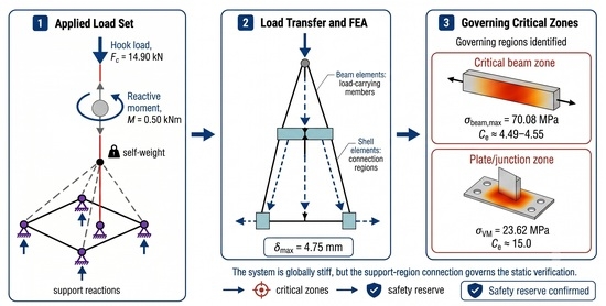
The present study is rooted in that practical and normative context. The load case analyzed here is not an arbitrary numerical scenario, but a code-based load combination corresponding to the structural design logic of the FA125 rig. It includes the self-weight of the structure, the maximum hook load, and the reactive moment transmitted by the drilling head, which together define the governing static condition used for verification of the mast assembly. The finite element model was built in MSC Visual Nastran (Version 4D 2004, MSC.Software Corp., Newport Beach, CA, USA) using beam and shell elements, which makes it possible to capture both the response of slender structural members and the local stress state in the plate-type connection regions [
7]. This mixed beam–shell representation is particularly suitable for drilling mast structures, where the critical response is usually shared between long members carrying axial and bending loads and local plate details carrying concentrated connection effects.
Against this background, advanced polymer composite systems are increasingly discussed for upgrading or replacing metallic structural components due to their superior specific stiffness [
8,
9,
10]. While our previous work [
11] targeted the dynamic domain—addressing modal behavior, transient pull-out response, and harmonic excitations—the specific scope of this communication is strictly restricted to the static load path under code-compliant criteria. However, prior to implementing such lightweight materials, the present study establishes a rigorous static reference framework for the FA125 drilling rig by shifting the focus entirely toward its governing design condition, incorporating international structural guidelines such as topside and offshore design standards [
12,
13].This static reference baseline is an indispensable prerequisite before attempting to integrate advanced structural composites, such as Glass Fiber Reinforced Polymers (GFRP) or Basalt Fiber Reinforced Polymers (BFRP), which have been extensively studied in other structural and infrastructural lightweighting contexts [
14,
15,
16,
17,
18].
The investigation is centered on resolving three fundamental engineering questions: first, whether the structural assembly satisfies the statutory static requirements under peak service loading; second, which specific beam members and connection joints govern the structural capacity; and third, the exact magnitude of the remaining safety margins within the current steel configuration. Consequently, the core novelty of this work lies in providing a calibrated mixed beam–shell finite element mapping that isolates member-level normal stresses and shell-level von Mises hotspots simultaneously. This provides a necessary and distinct engineering baseline for future selective optimization and local reinforcement strategies.
2. Materials and Methods
This study evaluates the static structural response of the FA125 drilling rig mast under representative operational loading conditions. The study focused on identifying the structural stiffness, stress distribution, and overall load-bearing performance while maintaining an identical geometric configuration for all investigated structural variants [
4,
5,
6,
7,
12].
2.1. Geometric Model and Structural Configuration
The structural framework under investigation belongs to the mast assembly of the FA125 hydraulic drilling rig, a mobile system specifically engineered for hydrogeological exploration and geotechnical drilling [
1,
2,
3].
Mechanically, the mast operates as a spatial truss-type structure rising to a nominal height of approximately 7.5 m. Its load-bearing skeleton consists of longitudinal columns, diagonal bracing lattices, and transverse reinforcement cross-members, all shifting operational demands down to the integrated base connections of the drilling platform.
Designing such a mast involves a delicate balance: the lattice must withstand severe axial pulling forces and bending moments during drill string extractions, yet comply with strict weight and transport constraints inherent to mobile equipment [
1,
2,
3].
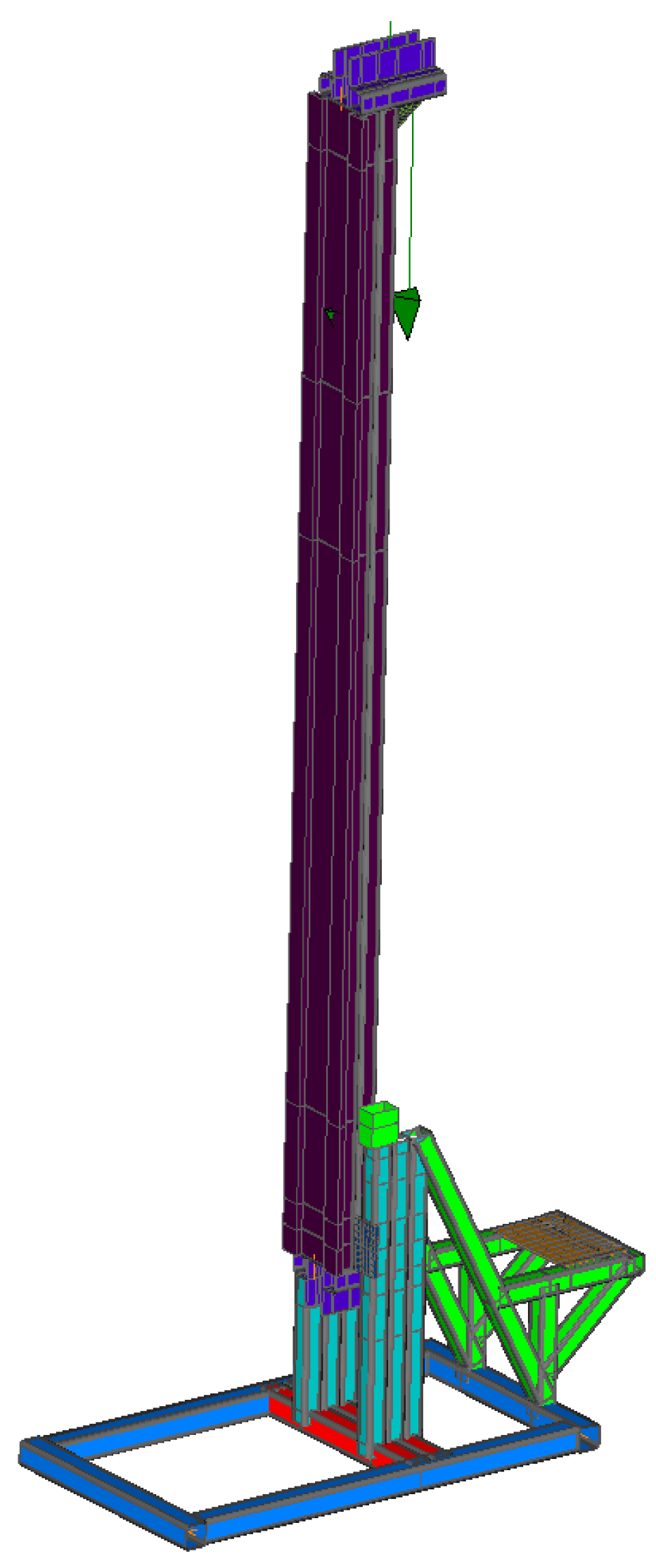
The same geometric configuration was retained throughout the static verification in order to isolate the effect of the governing load combination on the complete mast–support–base assembly. This approach allows the structural response to be interpreted in terms of load path, support transfer, member-level stress and local plate stress concentration (see
Figure 1).
This topological consistency ensures that the computed response can be interpreted in relation to the adopted static load combination, boundary conditions, and load-transfer path.
The resulting finite element model maps the primary structural components alongside their critical load-transfer zones.
We placed particular emphasis on discretizing the structural junctions and geometric transitions, as these interface regions are traditionally prone to localized stress concentrations during heavy drilling phases [
5,
6].
2.2. Material Models and Mechanical Properties
The primary numerical verification was carried out for the existing steel configuration of the FA125 mast. Since the objective of the paper is static safety assessment rather than full material optimization, the analysis focuses on the real load-bearing steel structure and on the identification of the members and joints that govern the static response. Composite or hybrid material solutions are mentioned only as possible future redesign directions and are not treated as the main result of the present investigation.
The steel configuration was based on a conventional structural steel grade frequently employed in industrial mechanical structures and drilling support assemblies due to its high mechanical resistance and established manufacturing applicability.
Since the main objective of the present paper is the static verification of the existing steel structure, the steel configuration remains the reference case throughout the analysis. The principal mechanical properties adopted in the finite element simulations are summarized in
Table 1.
The validated CAD geometry was imported into MSC Visual Nastran (Version 4D 2004, MSC.Software Corp., Newport Beach, CA, USA) to build the numerical model of the complete mast–support–base assembly. The reference static verification was performed for the existing steel structure, while the composite material data were retained only as a secondary outlook for future selective redesign.
2.3. Finite Element Modeling Strategy
The numerical simulations were performed using the MSC Visual Nastran finite element environment [
7].
The structural model was developed using beam-type finite elements suitable for the representation of slender structural members subjected to combined axial, bending, and shear loading conditions.
Similar finite element approaches have also been successfully applied to mast-like structures and composite engineering materials [
4,
13,
19,
20].
Additional refinement was introduced in structural regions characterized by geometric discontinuities, load transfer concentrations, and support connections where elevated equivalent stresses were expected to develop.
The lower support regions of the mast assembly were modeled using constrained boundary conditions intended to reproduce the operational anchorage configuration of the drilling rig during static loading.
The imposed constraints limited translational and rotational degrees of freedom in accordance with the physical support conditions of the real structure.
To ensure numerical consistency throughout the comparative investigation, identical mesh topology, boundary conditions, and loading configurations were maintained for all material variants.
The finite element model employed beam elements for the primary load-bearing members and shell elements for the connection plates. A mesh sensitivity study involving three discretization levels (coarse, medium, and fine) was performed to confirm mesh-independent results. The verification mesh was subsequently adopted for all simulations, with local refinement applied in regions exhibiting high stress gradients.
The results of this convergence study, mapping the stabilization of global displacements and maximum equivalent stresses, are detailed in
Table 2. The minimal variance confirmed that the Medium mesh yields fully converged results with optimal computational efficiency.
The numerical convergence trend indicates a sharp stabilization of the results as the grid is refined. While a variance of 11.94% is observed between the Coarse and Medium configurations due to localized stress gradients in the shell elements, the variation between the Medium and Fine meshes drops significantly to just 1.40% for the peak stresses and 0.20% for the maximum displacements. This minimal discrepancy mathematically demonstrates that asymptotic convergence has been successfully achieved at the Medium mesh level, ensuring high numerical confidence for the subsequent static verifications.
To validate the structural response obtained from the finite element model, an independent analytical verification was conducted using a simplified beam–column structural idealization. The lattice mast was modeled as an equivalent cantilever section subjected to an axial compression force Fc = 14.90 kN and an eccentric tip bending moment M = 0.55 kNm.
The basic mechanical evaluation of normal stresses at the base cross-section yielded a theoretical compressive stress of σanalytic = 73.42 MPa. Comparing this analytical estimation with the maximum stress computed via FEA (σFEA = 70.08 MPa) reveals a relative discrepancy of only 4.5%.
2.4. Boundary Conditions and Anchor Modeling
To capture the true structural behavior of the FA125 assembly during peak operation, the boundary conditions were formulated based on the physical constraints of the drilling platform anchorage. Mechanical anchoring is achieved via heavy-duty bolt connections that link the lower support frame directly to the rig substructure.
In the finite element model, these boundary conditions were applied across the four primary ground nodes (nodes 185, 187, 192, and 189) located at the base support assembly.
The restraint configuration was mathematically defined as follows:
This fully prevents rigid body translation of the base support frame under the structural self-weight and high axial vertical forces.
Rotational Constraints: Rotational degrees of freedom (Rx, Ry, Rz) were selectively evaluated. While the rigid anchorage limits macro-rotations to prevent overturning under the eccentric action of the hook load and the drilling-head reactive moment, partial localized rotational compliance was accounted for to reflect the structural flexibility of the baseline weldments and bolt pretension at the support plates.
Conversely, the top region of the vertical lattice mast is completely unrestrained, remaining free to deform and deflect under the combined axial pulling forces and bending moments transmitted through the upper operational zones.
2.5. Static Loading Conditions
The static loading configuration considered within the present investigation was established based on representative operational conditions associated with drilling and lifting operations.
The loading scenario included the contribution of:
Structural self-weight;
Operational axial loading generated by the drill string assembly;
Concentrated loading introduced through the upper operational region of the mast;
Supplementary structural reactions associated with the load transfer mechanism.
The gravitational loading contribution was automatically introduced according to the material density associated with each investigated structural configuration.
Special attention was given to the operational loading transmitted through the upper mast region, since this area represents one of the most critical structural zones during drilling operations. The adopted loading configuration was intended to reproduce realistic service conditions capable of generating representative stress and deformation fields within the structure [
2,
4,
11].
2.6. Governing Load Combination and Verification Criteria
The static assessment presented in this paper moves away from generic loading scenarios to focus strictly on the governing design combination adopted during the structural verification stage of the FA125 mast.
This specific combination covers the most demanding operational state of the assembly by superimposing the structural self-weight, the maximum hook load, and the reactive torque transmitted by the drilling head.
In this study, we reposition that traditional engineering logic within the modern, globally active design frameworks represented by SR EN ISO 13626:2010 and API Spec 4F [
5,
6,
12].
For the finite element model, the governing static load combination was defined as:
where LC
self represents the gravitational self-weight of the complete load-bearing assembly, LC
hook is the maximum hook load applied through the upper operational region of the mast, and LC
moment is the reactive moment generated by the drilling head during operation.
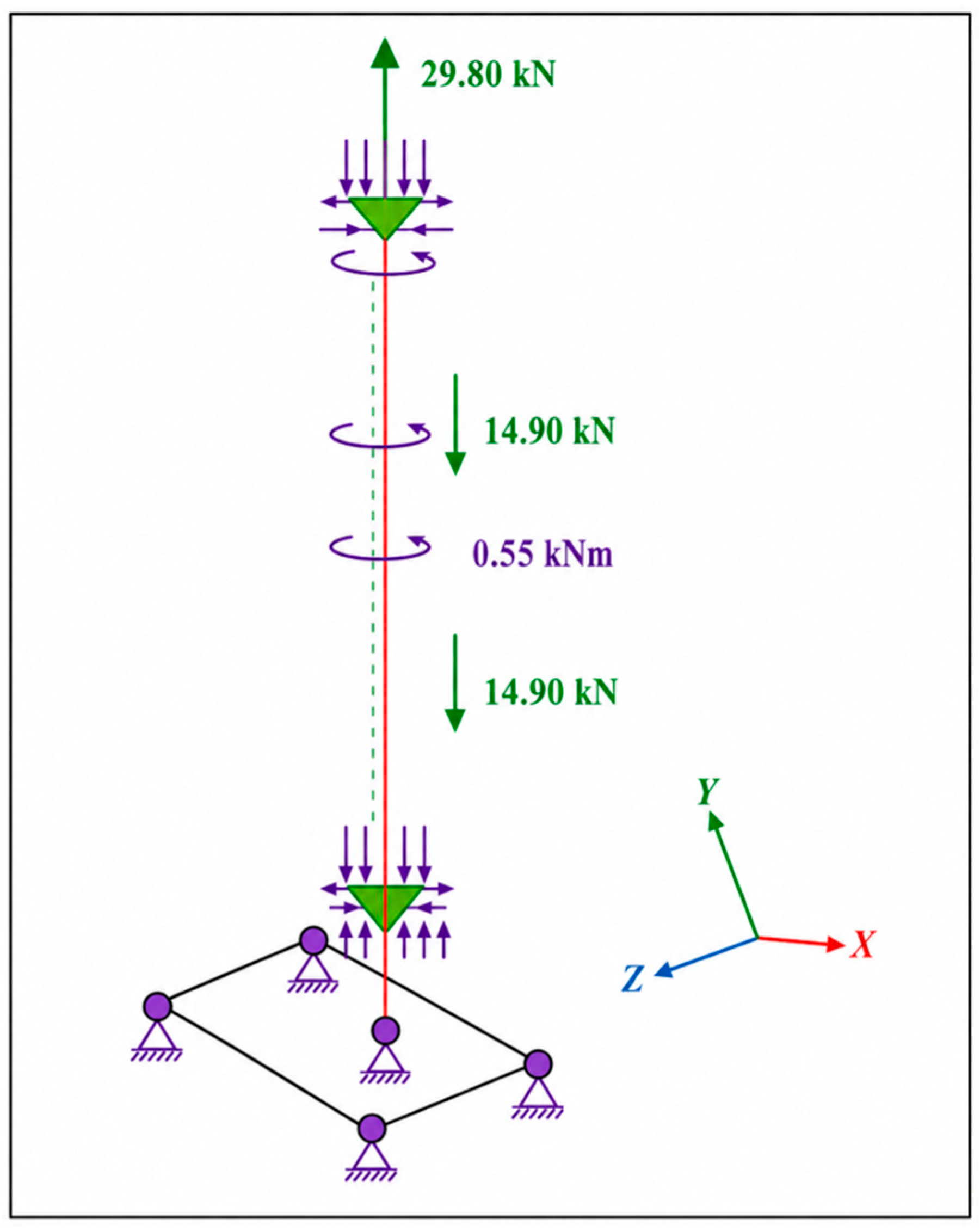
In numerical terms, the hook load was Fc = 1490 daN, corresponding to 14.90 kN, while the reactive drilling-head moment was M = 5500 daN·cm, corresponding to 0.55 kN·m. These values were applied as nodal force and nodal moment components in the masthead region, according to the structural design data available for the FA125 rig.
The loading scheme was introduced directly into the finite element model through nodal forces and nodal moment components distributed in the corresponding structural zones of the mast head and drilling-head support region.
This load combination targets the full structural assembly—mast, support frame, and base—rather than isolating individual beams. Because the system mixes slender columns with heavy joint plates, the structural components interact continuously during load transfer.
We applied the boundary constraints at four primary ground nodes in the base region where the real structure anchors to the soil. This localized constraint strategy forces the FEA solver to output explicit reaction patterns at the anchoring points, providing a clear map of the overall structural load path.
Our verification sequence evaluates three distinct structural responses.
First, the global displacement field maps the overall rigidity of the mast under load case C1, verifying that top-mast deflections do not jeopardize drilling alignment.
Second, we check the critical cross-sections of the beam elements for peak tensile and compressive stresses, comparing them against material yield limits to derive effective safety factors.
Then, we isolate the plate connections via a shell-element sub-model to analyze local von Mises stresses. This local shell-level assessment catches stress concentrations caused by joint eccentricities that standard beam models routinely overlook.
The verification itself was based on three categories of structural response.
First, the global displacement field was examined in order to assess the overall stiffness of the mast under the governing load combination. Particular attention was given to the mast-top displacement, since excessive deformation in this region may affect operational alignment, drilling precision, and the stability of the technological chain.
Second, the beam-type structural members were evaluated in terms of the maximum tensile and compressive stresses developed in the critical sections. These members govern the main load-transfer path from the mast toward the base support and were checked against the admissible strength conditions associated with the materials used in the structure.
The comparison was made by relating the computed stress level to the corresponding yielding strength and by calculating the effective safety coefficient for the most loaded members.
Third, the plate-type connection regions modeled with shell elements were evaluated through the equivalent von Mises stress. This was especially relevant in the mast-to-support connection area, where local stress concentration is more likely to occur because of geometric discontinuities and force transfer through bolted or welded plate assemblies.
In these regions, the structural response cannot be judged only from the behavior of the global beam members; a local shell-level assessment is necessary.
Based on this verification logic, the structural response was interpreted through the following engineering indicators: maximum mast displacement, maximum compressive stress in beam members, maximum tensile stress in beam members, maximum von Mises stress in shell regions, effective safety coefficients, and support reactions.
Together, these quantities provide a direct image of the governing static behavior of the FA125 mast and make it possible to identify the members and connection zones that control the strength assessment under the reference load combination.
The role of this section, therefore, is not to claim that the present study exhausts all relevant structural scenarios. Wind loading, fatigue effects, repeated operational cycles, and dynamic amplification remain important topics for subsequent work.
However, before such extensions can be addressed in a meaningful way, the governing static combination must first be understood clearly.
In that sense, the C1 case provides the basic structural reference for the present paper and also the necessary starting point for future redesign, local reinforcement, or selective material substitution studies.
2.7. Structural Verification Criteria
The structural assessment was performed through the evaluation of global deformation behavior and equivalent stress distribution developed within the mast structure under static loading conditions.
The maximum displacement values obtained from the finite element simulations were used to evaluate the global stiffness behavior of the investigated structural configuration. Excessive deformation levels may negatively influence drilling precision, operational stability, and long-term structural reliability.
Equivalent stress distributions were evaluated using the von Mises criterion for the steel plate regions, while beam-member stresses were assessed through the maximum tensile and compressive normal stresses. The verification was performed primarily for the existing steel configuration. The composite material data retained in the manuscript are used only as a secondary outlook for future selective redesign and are not treated as the central verification result.
3. Results and Discussion
The finite element simulations give a coherent picture of the static response of the FA125 drilling mast under the governing load combination C1. In the revised interpretation adopted in this manuscript, the main value of the results is not simply that the structure remains below the admissible limits, but that the analysis makes it possible to identify the actual static load path, the members that govern the verification, and the local joint regions where stress concentration must be watched more carefully.
Unlike the previously published dynamic study on the same platform [
11], the present section is centered on the static design condition defined by self-weight, maximum hook load, and drilling-head reactive moment.
For this reason, the discussion below is organized around three complementary aspects: the global deformation of the mast assembly, the beam members that govern the static response, and the plate-type joint regions where the local equivalent stress becomes relevant for the final assessment.
3.1. Global Deformation Under the Governing Static Combination
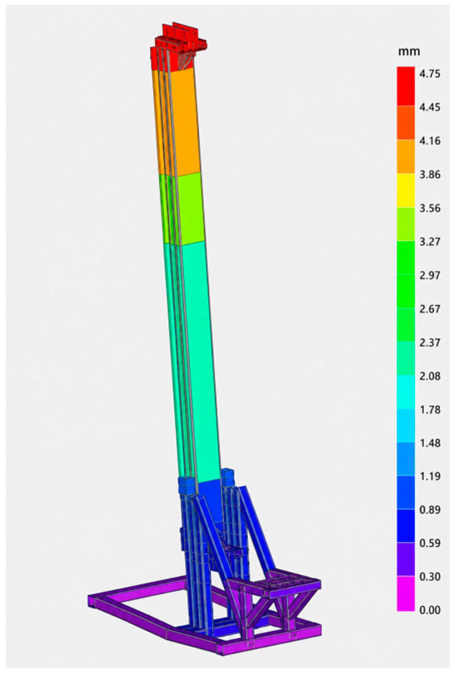
The deformed shape obtained from the finite element model confirms the expected behavior of the FA125 mast as a slender load-bearing assembly subjected to combined axial and bending effects. The largest displacement develops in the upper part of the mast, close to the mast head, where the cumulative effect of the applied operational loads produces the highest bending demand. This is consistent with the general behavior reported for mast-type and derrick-type support structures analyzed by numerical methods [
1,
2,
4].
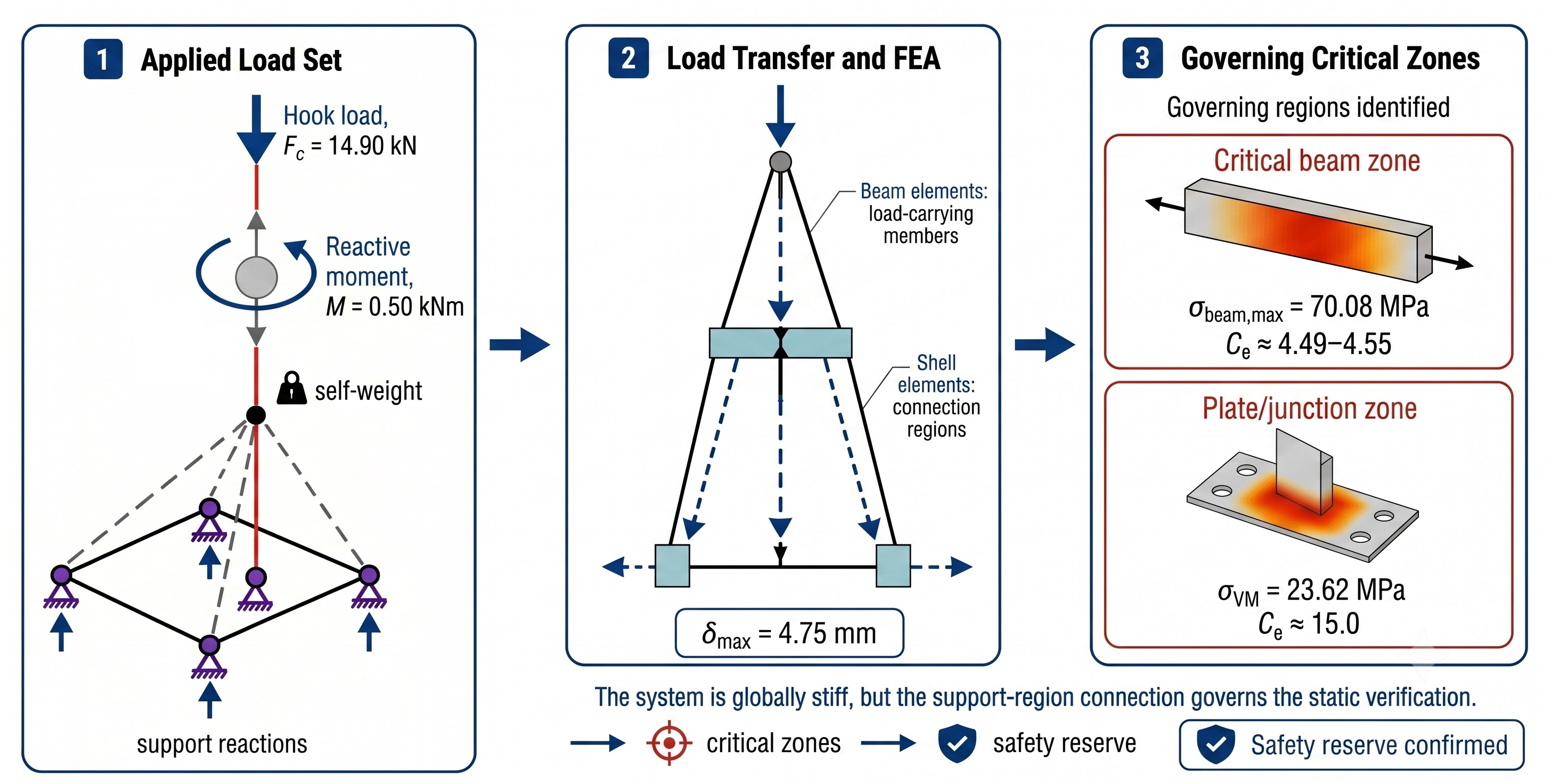
For the governing load combination C1, the maximum displacement at the mast top reaches 4.75 mm. Relative to the total structural height, this remains a modest value and indicates that the current steel configuration preserves an adequate stiffness reserve under the reference static condition.
In practical terms, the result suggests that the FA125 mast is able to maintain a satisfactory global geometric response during operation, without excessive lateral deviation in the mast head or loss of structural coherence in the support assembly.
This displacement result should not be read only as a global service indicator. It also provides the deformation background against which the local stress field must be interpreted. In other words, the structure does not fail by a large visible global distortion; instead, the governing static problem is associated with how the loads are redistributed through a limited number of members and joints while the overall mast remains relatively stiff.
The governing loading scheme and the corresponding support conditions are shown in
Figure 2.
3.2. Support Reactions and Load-Transfer Path
The reaction forces at the four constrained base nodes were extracted in order to check the global equilibrium of the finite element model and to identify the dominant static load-transfer path. The support nodes considered in the analysis were nodes 185, 187, 192, and 189, corresponding to the anchoring points of the base support. The resulting reactions are summarized in
Table 3.
The total vertical reaction obtained from the finite element model was 16.81 kN. This value is consistent with the applied hook load of 14.90 kN and the structural self-weight of approximately 1.90 kN, confirming the global equilibrium of the static model. The horizontal reaction components are self-balanced, with total Rx and Rz values approximately equal to zero. This confirms that the support system correctly balances the eccentric action produced by the hook load and the drilling-head reactive moment.
The distribution of the vertical reactions is not uniform. The highest vertical reactions are obtained at nodes 192 and 189, with Ry values of 4.86 kN and 5.33 kN, respectively. This indicates that the governing static load path is transferred preferentially through the lower support frame and anchoring region. This reaction pattern explains why the maximum beam stresses are located in the lateral base-support members rather than in the upper mast region.
These support reactions confirm that the base support is not only a boundary region, but an active load-transfer component of the FA125 structure. Therefore, the subsequent member-level verification is focused on the lateral base-support members, where the finite element model indicates the highest tensile and compressive stresses.
For the conventional steel configuration (see
Figure 3), the deformation pattern exhibited a progressive increase in displacement along the mast height, with the largest deformation values concentrated near the mast head region. This behavior is characteristic of slender truss-type load-bearing structures subjected to combined axial and bending loading conditions [
1,
2,
10].
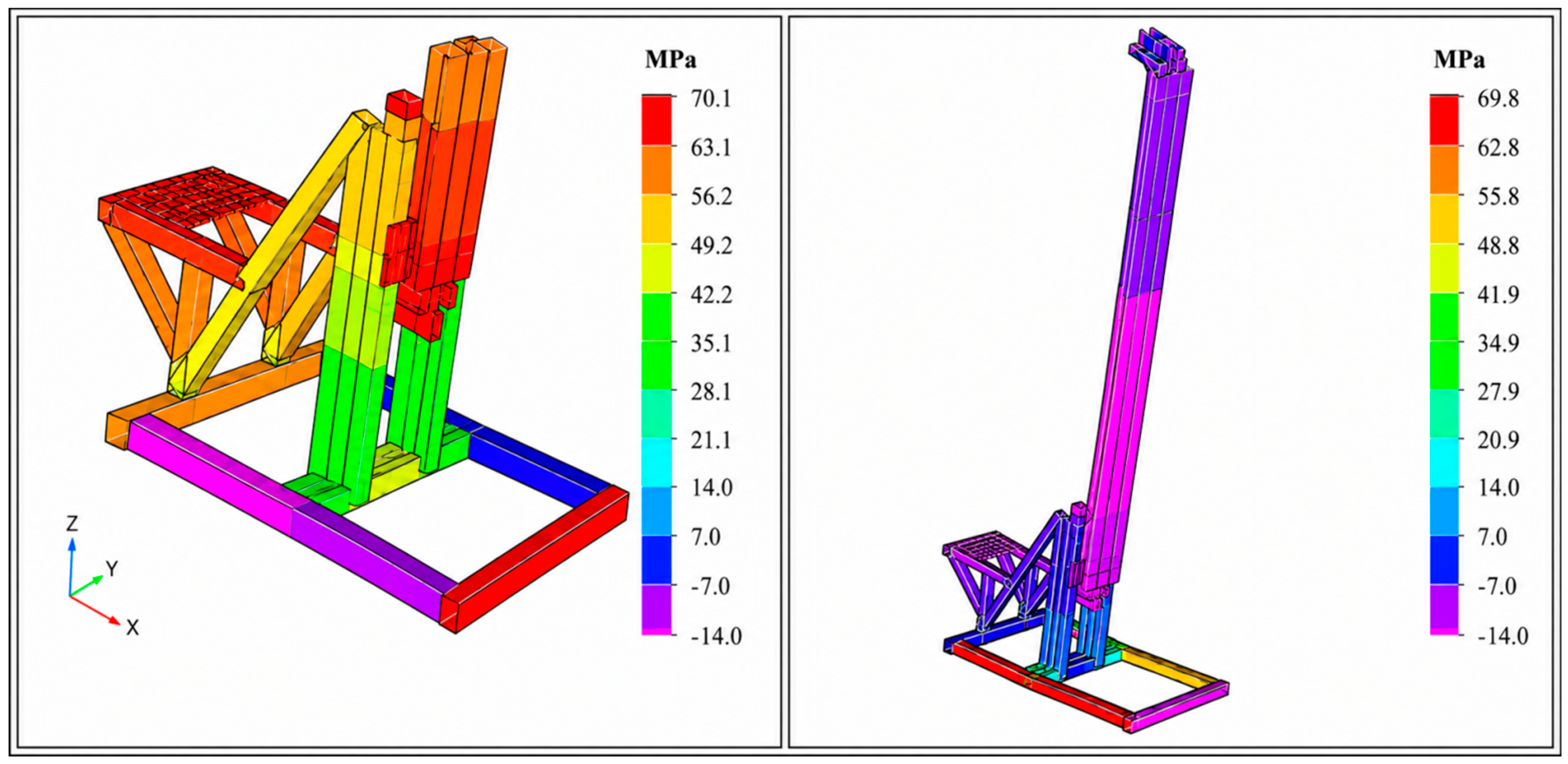
A more informative result emerges from the stress field. The beam-type elements that govern the static verification are not located in the visually dominant upper mast region, but in the lateral left-hand zone of the base support.
More precisely, the critical members are the square hollow sections of 60 × 60 × 4 mm that participate directly in transferring the mast loads toward the support frame and anchoring region.
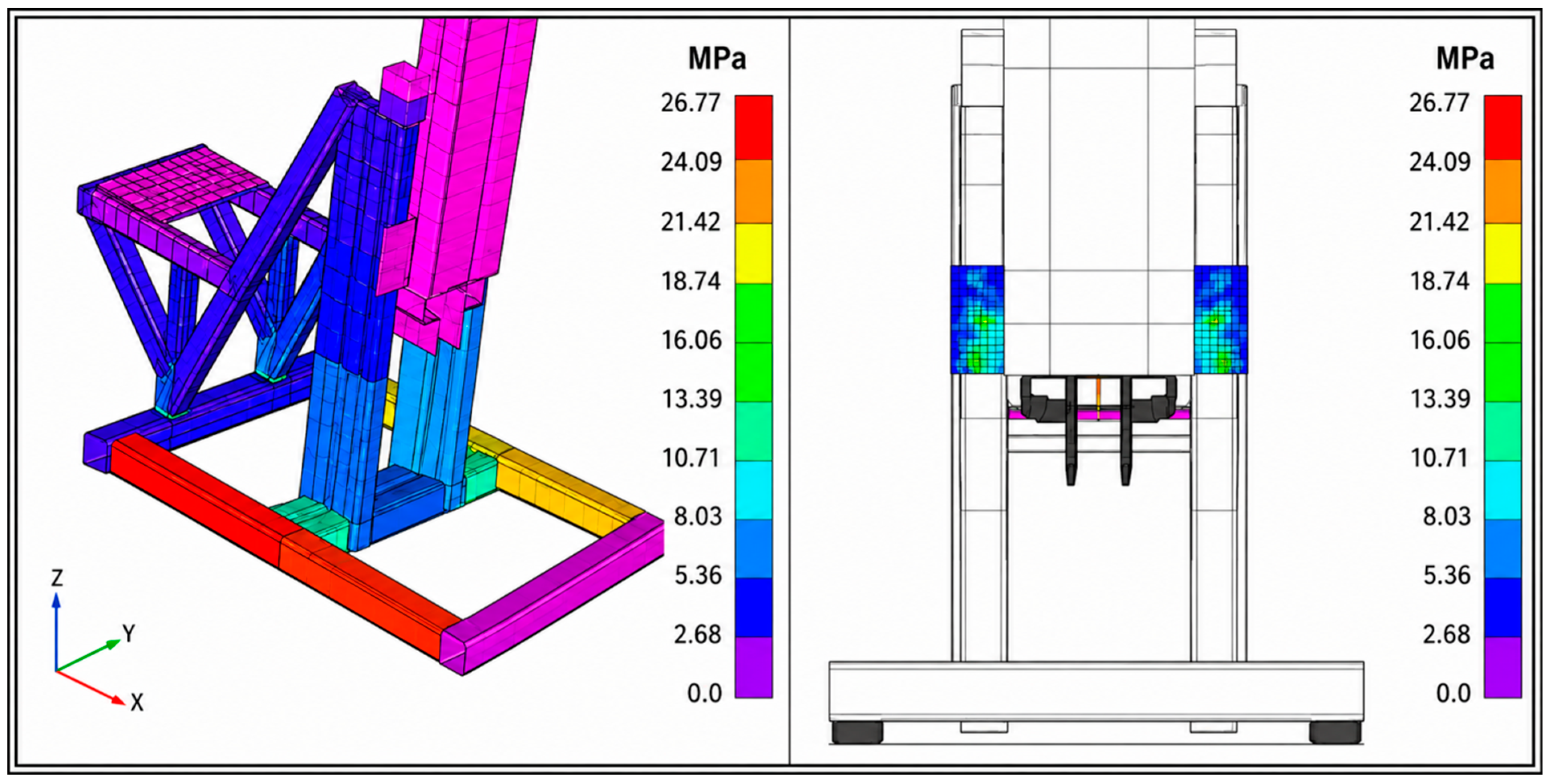
This is one of the most useful outcomes of the present analysis, because it identifies the real governing members of the structure rather than the intuitively expected ones. Their location and stress pattern are illustrated in
Figure 4.
This interpretation is more useful for design than a simple statement that the structure remains below admissible limits, because it identifies where the real structural sensitivity is located.
3.3. Member-Level Verification of the Lateral Base-Support Region
The member-level verification was carried out on the beam elements located in the lateral base-support region, where the finite element results indicated the highest normal stresses. The critical members are square hollow sections of 60 × 60 × 4 mm, which participate directly in the transfer of mast loads toward the support frame and the anchoring region.
The maximum compressive stress obtained in these members was σ
c = 70.08 MPa, while the maximum tensile stress was σ
t = 69.21 MPa. The beam-member verification was governed by E315 steel, with effective safety coefficients of 4.49 in compression and 4.55 in tension. These values remain well above the minimum safety coefficients recommended by STAS 1909-89 (or by SR EN ISO 13626:2010 [
6], currently in force) and confirm that the governing beam members remain below the adopted strength limits.
The member-level structural safety was explicitly verified against the limit state design criteria outlined in SR EN ISO 13626:2010 [
6]. The fundamental verification condition for the normal stresses developed in the critical beam sections is expressed as follows:
where
is the computed maximum effective normal stress (70.08 MPa in compression and 69.21 MPa in tension), Ry is the nominal yield strength of the E315/S315 structural steel (315 MPa) and
is the partial material safety factor taken as 1.10, according to code regulation. This yields an allowable design stress limit of
286.36 MPa. Since
= 70.08 MPa ≤ 286.36 MPa, the structural safety condition is fully satisfied, leaving a substantial engineering margin.
These values confirm that the governing beam members remain well below the adopted reference strength. At the same time, the result is important from a design perspective because it shows that the lower support-transfer region governs the member-level static response. Therefore, future redesign, local reinforcement, or selective material substitution should begin with this base-support load path rather than with a uniform intervention applied to the complete mast structure.
If some of the corresponding members are later confirmed as S355J2 during the detailed fabrication review, the resulting safety coefficients would be higher. However, the conservative 315 MPa reference is retained here as the main verification basis in order to avoid overestimating the available structural reserve.
The most severe compressive and tensile stresses are concentrated in the lateral square hollow sections that control the member-level static verification (see
Figure 4).
3.4. Shell-Level Verification of Mast-to-Support Plates
The shell-level verification was focused on the mast-to-support connection plates, where the load transfer between the mast and the lower support assembly produces local stress concentrations (see
Figure 5).
This region cannot be evaluated only through the beam-member results, because the plate geometry, local eccentricity of the load path, and connection layout may generate local von Mises stress peaks.
The maximum equivalent von Mises stress obtained in the connection plates was approximately 23.62 MPa. The plate verification was governed by S355J2 steel, with a nominal yielding strength of 355 MPa. The resulting effective safety coefficient is approximately 15.0, which remains significantly higher than the minimum value recommended by SR EN ISO 13626:2010 [
6], currently in force.
Although the numerical safety reserve is high, this region remains structurally important because it represents the principal local interface through which forces are transferred from the mast into the support frame. For this reason, the mast-to-support plates should remain a priority location for future experimental strain monitoring, weld-level inspection, fatigue assessment, or local reinforcement studies.
The localized stress concentration phenomena observed within the connection plates are primarily driven by geometric discontinuities and abrupt changes in the load-transfer path. The high structural safety factor calculated for these shell elements (approximately 15.0) aligns with established theoretical evaluations of geometric stress raisers. As demonstrated by Radojković et al. (2023) in their structural study of stress concentration zones, geometric transitions and opening boundaries are traditional sources of local stress peaks that require distinct shell-level assessment to safeguard against fatigue or localized micro-yielding, even when the global beam-like skeleton exhibits lower nominal stress states [
21].
3.5. Implications for Future Redesign
The present results should not be interpreted as a final material-substitution study. Instead, they provide a static structural map showing where any future lightweight or hybrid redesign should begin. The finite element results indicate that the governing static response is concentrated in two main regions: the lateral base-support members, which control the beam-level verification, and the mast-to-support connection plates, which control the local shell-level stress response.
This finding is important because the FA125 mast should not be approached as a uniform structure if a future lightweight upgrade is considered. Members with high safety reserve and moderate stiffness sensitivity may be considered first for selective redesign, whereas regions dominated by local connection effects, plate stiffness, weld behavior, or load eccentricity require more conservative treatment.
Composite or hybrid steel–composite solutions may therefore be relevant in later development stages, but only after the static load path, local connection behavior, joining technology, fatigue resistance, and dynamic response are evaluated together. In this sense, the present paper provides the static verification basis required before any credible discussion of GFRP, BFRP, CFRP, or hybrid material substitution can be made.
A structurally sound next step would be to combine the static map developed here with the dynamic findings already reported for the FA125 platform and then decide which members should remain metallic, which could be redesigned using lower-density materials, and which would require higher-stiffness or locally reinforced solutions.
Thus, the role of the present study is not to prescribe a final material replacement, but to identify the structural zones that matter most for future redesign.
4. Conclusions
This study examined the static response of the FA125 hydraulic drilling rig mast under its governing verification load combination (C1). The structural assessment was conducted on the complete load-bearing configuration—comprising the lattice mast, the support frame, and the base assembly—using a validated mixed beam–shell finite element representation capable of capturing both global stiffness fields and localized joint stress distributions.
The numerical and analytical results confirm that the existing FA125 steel structure satisfies the required static strength limits with a substantial engineering safety margin under the investigated loading scenario. The maximum displacement developed at the mast top was limited to 4.75 mm, indicating that the current steel configuration preserves adequate global operational rigidity.
A critical outcome of the analysis is the quantitative localization of the structural regions that govern the verification load path. The most heavily loaded beam members were identified within the lateral base-support zone, where the 60 × 60 × 4 mm square hollow sections developed a peak compressive stress of 70.08 MPa and a peak tensile stress of 69.21 MPa. Utilizing the conservative design yield baseline for E315 structural steel (315 MPa), these stresses correspond to effective safety coefficients of 4.49 and 4.55, respectively. Concurrently, the governing local shell response occurs within the mast-to-support connection plates, where the peak localized von Mises stress reaches 23.62 MPa, yielding an effective safety factor of approximately 15.0 against the 355 MPa yield limit of S355J2 steel.
It must be explicitly emphasized that these quantitative safety margins and stiffness conclusions are strictly restricted to the investigated C1 design combination of structural self-weight, maximum hook load, and reactive drilling torque. Alternative operational and environmental scenarios—including dynamic wind profiles, non-symmetric cyclic extractions, and accidental impact overloads—remain outside the scope of this communication and must be addressed in subsequent structural investigations.
Future Outlook: While the present study is restricted to the static evaluation of the steel configuration, the established stress distribution map defines the necessary engineering baseline for subsequent structural lightweighting. Future work will leverage these numerical boundaries to investigate targeted, region-dependent material hybridization using Glass Fiber Reinforced Polymers (GFRP) or Basalt Fiber Reinforced Polymers (BFRP) exclusively on low-stress structural components [
14,
15,
16,
17,
18], moving toward experimental validation and localized strain-gauge monitoring under operational field cycles.