Article

Partitioned Calculation of Node-Level Carbon Emission Factors for Large-Scale Power Systems Based on Centralized Data Distribution Pattern and BiCGSTAB Algorithm

China Southern Power Grid Artificial Intelligence Technology Co., Ltd., Guangzhou 510000, China
*
Author to whom correspondence should be addressed.
Technologies 2026, 14(7), 420; https://doi.org/10.3390/technologies14070420
Submission received: 2 June 2026 / Revised: 30 June 2026 / Accepted: 4 July 2026 / Published: 9 July 2026

Abstract

With the advancement of the new-type power system construction, the accurate and efficient calculation of node-level carbon emission factors (CEFs) has become a key basis for indirect carbon emission accounting in power systems. Existing centralized methods face two major challenges in large-scale power grids: a heavy computational burden caused by the expanding scale of carbon emission flow equations, and potential privacy leakage caused by the centralized aggregation of regional operational data. To address these issues, this paper proposes a partitioned iterative CEF calculation framework based on the centralized data distribution pattern (CDDP) and the biconjugate gradient stabilized (BiCGSTAB) algorithm. The power grid is naturally divided into multiple subregions according to the power supply jurisdiction of each node. Each subregion independently solves its local CEF model, while a centralized broker coordinates boundary information exchange among regions. During this process, each region only discloses the required boundary-node CEFs, which is consistent with the mechanism of unified dispatch and hierarchical management. Tests on the 2000-node, 10,000-node, and 25,000-node systems show that the maximum relative errors are 0.00019%, 0.0030%, and 0.0900%, respectively. These results verify the effectiveness and scalability of the proposed framework and provide a feasible engineering solution for efficient, privacy-preserving node-level CEF calculation in large-scale power grids.

1. Introduction

Power system decarbonization is a central issue in the global response to climate change. As one of the largest sources of anthropogenic carbon dioxide (CO2) emissions worldwide, the power sector is under increasing pressure to transition toward a clean and low-carbon generation structure [1]. Under China’s dual-carbon strategy, the large-scale integration of renewable energy is fundamentally reshaping the structure and operating characteristics of power grids [2,3]. However, this transition has introduced unprecedented complexity in the fine-grained quantification and attribution of carbon emissions. Such a capability is essential for carbon emission trading, demand-side carbon management, and low-carbon dispatch decision-making [4,5].
The carbon emission factor (CEF) and carbon emission flow theory provide a solid theoretical basis for tracing generation-side carbon emissions as they are transmitted through power networks to end-use consumption nodes. Kang et al. [6] pioneered a network-based carbon emission flow model, in which carbon emissions were traced and quantified from generators to demand nodes according to the proportional sharing principle. Cheng et al. [7] further extended carbon emission flow theory to multi-energy systems and proposed a unified analytical framework for modeling carbon emission flows in power, natural gas, and heating networks. The nodal CEF, defined as the CO2 emission intensity per unit of electricity at each bus, has become a core metric for nodal-level carbon accounting and enables fair attribution of carbon responsibility between the generation and consumption sides [8,9]. Wang et al. [10] developed a data-driven carbon emission flow model based on Bayesian inference regression and applied it to carbon-intensity-oriented optimal power dispatch, demonstrating the practical value of nodal carbon accounting in power system operation.
Despite significant progress in carbon emission flow theory, the accurate and efficient calculation of nodal CEFs in large-scale power systems remains a critical challenge. Existing centralized methods usually formulate the carbon emission flow problem as a system of linear equations, whose coefficient matrix is constructed from the power flow results of the entire grid. Although these methods are mathematically rigorous, their direct application to large-scale systems with tens of thousands of nodes leads to a substantial computational burden and requires synchronous centralized access to sensitive operational data from different regions [11,12].
More specifically, centralized CEF calculation becomes practically constrained when the system scale reaches the ten-thousand-node level. In this case, full-network power-flow data, generation data, load information, regional partition information, and branch-flow data must be synchronously aggregated at a central computing entity. The practical limitations of centralized methods are mainly reflected in three aspects: the size of the full-network coefficient matrix to be solved, the amount of cross-regional operational data that must be uploaded, and the latency tolerance required by near-real-time carbon accounting applications.
In modern power systems operated under the principle of unified dispatch and hierarchical management, regional operators generally impose strict protection on their own generation and load data. Mandatory data centralization not only increases the risk of privacy leakage but also introduces potential single points of failure in the computational infrastructure [13]. In addition, practical power grids may contain isolated nodes due to changes in operating conditions, such as zero active power flow across certain sections, which can render the coefficient matrix singular. Traditional direct inversion methods therefore need to traverse and remove all-zero rows to ensure matrix invertibility. For power grids with tens of thousands of nodes, the resulting carbon emission flow linear system is extremely large, making direct solution methods difficult to apply in real-time or near-real-time scenarios [14].
To address the computational bottlenecks of large-scale centralized solvers, distributed and decomposition-based algorithms have received increasing attention in power system optimization. For example, the alternating direction method of multipliers (ADMM) has been investigated for distributed optimal power flow, where regional subsystems solve local subproblems independently and exchange only boundary information with neighboring regions [15,16]. Privacy-preserving distributed economic dispatch algorithms have also been developed to protect sensitive generation cost and output data during inter-regional coordination [17,18]. However, these methods are mainly designed for optimization problems and cannot be directly applied to carbon emission flow calculation models, whose coefficient matrices are nonsymmetric and highly sparse. At present, iterative methods for calculating CEFs in large-scale power systems have not yet been systematically investigated. Meanwhile, the biconjugate gradient stabilized algorithm (BiCGSTAB), proposed by Van der Vorst [19], has been widely used as an efficient Krylov subspace method for solving large sparse nonsymmetric linear systems. Compared with direct solvers, BiCGSTAB has lower memory requirements and smoother convergence behavior, making it particularly suitable for sparse and potentially ill-conditioned matrices in power systems [20]. If an effective outer-loop iteration mechanism can be designed to handle inter-regional boundary dependencies, BiCGSTAB can be used to efficiently solve regional carbon emission flow linear systems and substantially reduce the computational burden of each subproblem.
Recent studies have further highlighted the practical value of high-resolution and spatially refined CEF calculation from the perspective of downstream applications. Chen et al. [12] proposed a carbon-aware optimal power flow (C-OPF) framework that directly integrates nodal carbon intensity constraints into power dispatch optimization, demonstrating that spatially resolved CEFs can significantly improve the accuracy of carbon-constrained dispatch. Bu et al. [21] applied nodal carbon intensities derived from the carbon emission flow method to demand-side low-carbon energy management in buildings, showing that dynamic nodal factors can more accurately reflect real-time changes in the generation mix. Sang et al. [11] explored the encoding of carbon emission flow as compact learning constraints for energy management systems, further motivating the development of efficient carbon emission flow calculation methods. However, existing studies have mainly been validated on small- and medium-scale test systems, and no systematic solution has yet been proposed for efficient nodal CEF calculation in large-scale power systems with thousands or even tens of thousands of nodes.
To fill this critical gap, this paper proposes a partitioned calculation framework for nodal CEFs in large-scale power systems based on a centralized data distribution mode and the BiCGSTAB algorithm. In the proposed framework, the entire power system is naturally divided into multiple regional grids according to the supply jurisdictions of nodes. Each subregion independently solves its local carbon emission flow linear system using BiCGSTAB. A centralized broker (CB) collects the CEFs of boundary nodes from all subregions and redistributes them according to predefined data subscription templates, thereby coordinating inter-regional information exchange in a unified manner. This architecture is highly consistent with the practical operation principle of unified dispatch and hierarchical management. The outer-loop iteration continues until the boundary CEFs converge, ensuring that the distributed solution satisfies practical engineering accuracy requirements. The scalability and accuracy of the proposed method are verified on test systems with 2000 nodes and 8 regions, 10,000 nodes and 16 regions, and 25,000 nodes and 31 regions.
Existing methods for nodal CEF calculation can be broadly divided into centralized carbon emission flow models and optimization-oriented frameworks such as carbon-aware optimal power flow. However, the former becomes computationally heavy and privacy-sensitive at the ten-thousand-node level, while the latter is not designed for large-scale CEF computation. To address this gap, the specific research objectives and contributions of this study are summarized as follows.
The specific research objectives of this study and the corresponding contributions are summarized as follows:
(a)
A partitioned CEF calculation framework compatible with the “unified dispatch and hierarchical management” organizational structure of new-type power systems is established. In the proposed framework, each regional management entity only needs to disclose boundary-node CEFs, thereby helping to protect operational privacy.
(b)
The BiCGSTAB algorithm is introduced to solve the nonsymmetric carbon emission flow model within each region. The convergence behavior of the inner and outer iterations is also analyzed.
(c)
Large-scale validation is carried out on systems with up to 25,000 nodes, demonstrating the feasibility of the proposed method for engineering implementation in large-scale new-type power systems.
To further clarify the methodological differences, Table 1 compares the proposed CDDP-BiCGSTAB framework with representative existing CEF methods.
The remainder of this paper is organized as follows. Section 2 presents the mathematical formulation of node-level CEF calculation, the BiCGSTAB-based solution method, and the proposed CDDP-based partitioned calculation framework. Section 3 describes the case-study systems, parameter settings, and numerical results. Section 4 discusses the convergence behavior, engineering applicability, parameter sensitivity, and limitations of the proposed framework. Section 5 concludes the paper and outlines future research directions.

2. Methodology

The main symbols used in the methodology are summarized in Table 2.

2.1. Derivation of Dynamic Carbon Emission Factor

According to the proportional sharing principle [21], all power flows leaving a node share the same carbon intensity as the power injected into that node. In other words, the CEF of a node is determined by the proportional weighting of all injected power flows. Assuming that the system contains n nodes, the node-level CEF vector of the entire network is defined as:
e = e 1 , e 2 , , e n T
where e denotes the node-level CEF vector of the entire network, and e n denotes the CEF of node n (kgCO2/kWh).
Assume that node n is connected to G n in-service generators, and the active power output of the g generator is P g , n . Then, the carbon balance equation of node n can be expressed as:
g = 1 G n P g , n + j U n f j n e n = g = 1 G n P g , n ε g , n + j U n f j n e j
where U n denotes the set of upstream nodes that actually inject active power into node n , and f j n denotes the active power injected into node n through branch (j- n ), with f j n > 0 .
According to Equation (2), the total power received by node n multiplied by its corresponding CEF is equal to the sum of local generation carbon emissions and upstream transmitted carbon emissions. Therefore, by formulating the carbon balance equation for each node in the entire network, the following linear equation system can be obtained [22]:
A e = b
where A is the coefficient matrix, and b is the constant vector.
The elements of the coefficient matrix are uniquely determined by the power flow distribution:
A n n = g = 1 G n P g , n + j U n f j n , A n j = f j n , j U n 0 , j U n
The n -th element of the constant vector is given by:
b n = g = 1 G n P g , n ε g , n
where A n n denotes the total active power received by node n (kW); the off-diagonal element A n j reflects the contribution of upstream carbon intensity to the current node through its negative sign; and b n denotes the sum of carbon emissions from local generators connected to node n . If no generator is connected to the node, this term is equal to zero.
The CEF values of different generator types used in this study are summarized in Table 1 according to generator type [23,24].

2.2. Solution Method Based on the BiCGSTAB Algorithm

In this paper, the BiCGSTAB algorithm is adopted as the solver. Compared with GMRES, BiCGSTAB has a fixed memory cost in each iteration, which does not increase with the number of iterations. Each iteration only requires two matrix-vector multiplications. Moreover, its convergence curve is smoother than those of BiCG and CGS, which helps avoid the risk of residual explosion.
The CEF coefficient matrix constructed from power-flow directions is generally nonsymmetric and highly sparse because only upstream active-power injections contribute to the carbon balance of each node. Therefore, classical methods designed for symmetric positive definite systems, such as the conjugate gradient method, are not directly applicable. Compared with optimization-oriented distributed solvers such as ADMM, BiCGSTAB is more suitable for the present problem because the CEF calculation is formulated as a sparse linear equation system rather than an optimization problem with an explicit objective function and constraints. Therefore, the objective of this study is not to minimize or maximize an objective function, but to obtain the node-level CEF vector that satisfies the carbon balance equations and the boundary-consistency condition among subregions. The corresponding mathematical formulation is given by the full-network CEF equation system in Equations (2)–(5), the subregional equation system in Equation (12), and the boundary update and convergence conditions in Equations (13)–(17).These characteristics make BiCGSTAB a suitable inner-layer solver for the proposed partitioned CEF calculation framework.
BiCGSTAB constructs the approximate solution within the Krylov subspace. The approximate solution at the n -th iteration satisfies:
e k e 0 + K k A , r 0
where e 0 = 0 is the zero initial solution; r 0 = b A e 0 is the initial residual; and K k A , r 0 = s p a n { r 0 , A r 0 , , A k 1 r 0 } is the k -th order Krylov subspace.
Initialization (k = 0): let r ^ = r 0 , p 0 = r 0 , ρ 0 = α 0 = ω 0 = 1 .
For the ( k + 1 )-th iteration, the update process is expressed as:
ρ k + 1 = r ^ T r k , β k = ρ k + 1 ρ k α k ω k , p k + 1 = r k + β k p k ω k v k
v k + 1 = A p k + 1 , α k + 1 = ρ k + 1 r ^ T v k + 1 , s k + 1 = r k α k + 1 v k + 1
t k + 1 = A s k + 1 , ω k + 1 = t k + 1 T s k + 1 t k + 1 T t k + 1
e k + 1 = e k + α k + 1 p k + 1 + ω k + 1 s k + 1 , r k + 1 = s k + 1 ω k + 1 t k + 1
where r ^ is the shadow residual vector, which is set as r ^ = r 0 and remains unchanged during the iteration; ρ k is the inner product scalar with the current residual; β k is the search direction update coefficient; p k is the search direction vector; v k and t k are intermediate variables in matrix-vector multiplication; α k is the BiCG step length; s k is the intermediate residual vector; and ω k is the optimal step length obtained by minimizing s k ω t k 2 .
The convergence criterion is defined by the relative residual norm:
η k = r k 2 b 2 ε i n n e r
where η k is the inner-layer relative residual at the k-th step, and ε i n n e r is the inner-layer convergence threshold. When η k ε i n n e r is satisfied, the algorithm terminates and outputs the current solution as the subregional CEF solution for the current outer iteration. The total computational complexity of a single iteration is O n n z A , where n n z A denotes the number of nonzero elements in the matrix, which is much lower than that of the direct method.
More details of the BiCGSTAB algorithm can be found in ref. [15].
In the proposed CDDP-BiCGSTAB framework, the above BiCGSTAB procedure is implemented as the inner-layer solver for each subregional CEF linear equation system. In the first outer iteration, the initial solution of each subregion is set to zero. In subsequent outer iterations, the converged solution from the previous outer iteration is used as the initial solution of the current iteration to accelerate convergence. For each outer iteration, every subregion updates its local right-hand-side vector according to the received boundary-node CEFs, solves the local sparse nonsymmetric equation system using BiCGSTAB, and then submits the updated boundary-node CEFs to the centralized broker for the next outer-layer update.

2.3. CDDP-Based Partitioned CEF Calculation Framework

The proposed partitioned calculation framework for node-level CEFs based on the centralized data distribution pattern (CDDP) is shown in Figure 1. For m subregions, the centralized broker coordinates the collection and distribution of boundary information in a unified manner. Each subregion independently completes its internal solution using BiCGSTAB, and regional operators do not need to share internal data.
The indices used in Figure 1 and throughout this section are defined as follows. The full power system is divided into M non-overlapping subregions. The m-th subregion is indexed by m ∈ {1, 2, …, M}, and the corresponding set of nodes is denoted by R m . The set of boundary nodes in subregion m is denoted by R m b n d , and the set of opposite-side nodes injecting power into subregion m is denoted by O m .
The numbered data-flow steps in Figure 1 are directly linked to the mathematical formulation in this section. Step 1 receives the opposite-side boundary CEFs distributed by the centralized broker, corresponding to the boundary information exchange described in Equations (15) and (16). Step 2 updates the subregional vector according to the boundary coupling relation in Equations (13) and (14). Step 3 solves the subregional CEF equation system in Equation (12) using BiCGSTAB until the inner-layer convergence criterion in Equation (11) is satisfied. Step 4 uploads the updated boundary CEFs to the centralized broker for aggregation, redistribution, and outer-layer convergence checking according to Equations (16) and (17).

2.3.1. Region Decomposition and Subregional Equation Construction

The power system containing n nodes is divided into m non-overlapping subregions, denoted as { R 1 , , R m } . These subregions satisfy the following relationships: m R m = n , R m R m = m m , N m = R m , m N m = n .
For the N m nodes in subregion R m , the subregional linear equation system is constructed according to Equations (2)–(5):
A m e m = b m
where A m is the coefficient matrix of subregion m; e m is the node-level CEF vector to be solved; and b m is the constant vector.
The construction of A m is completely consistent with that of the full-network matrix A. The main difference lies in b m . For a boundary node n R m b n d that receives cross-regional power injection, the corresponding element of b m contains the carbon contribution from the opposite-side node:
b m , n = g = 1 G n P g , n ε g , n + j O m U n f j n e j
where R m b n d denotes the set of boundary nodes in subregion m that receive cross-regional active power injection; O m denotes the set of all opposite-side nodes injecting power into region m; and e j is the CEF of opposite-side node j, which is the core variable transmitted in the interregional iteration.
The vector b m is decomposed into a local fixed term and a boundary coupling term:
b m = b m l o c + C m e m o f f
where b m l o c is the local carbon emission vector determined only by generators within the subregion and remains fixed throughout the iteration; C m is the boundary coupling matrix, whose element at position (n, j) is equal to f j n ; and e m o f f is the CEF vector of opposite-side nodes.
According to Equation (14), A m remains unchanged throughout the iteration, and only b m needs to be updated in each outer iteration, resulting in very low computational overhead. The directional screening of boundary nodes ensures that only cross-regional branches with power actually flowing into the subregion are included in e m o f f , thereby guaranteeing the physical consistency of carbon emission flow tracing.

2.3.2. Centralized Data Distribution Protocol

The proposed framework adopts a star-shaped communication topology, in which each subregion communicates only with the CB, and no direct data exchange is required among different subregions. Each regional operator only submits the CEFs of boundary nodes to the CB. Internal generation parameters, load data, and branch power flow data do not need to be disclosed externally, which is consistent with the dispatch mechanism of unified dispatch and hierarchical management.
The communication protocol consists of two stages. The initialization stage is executed only once. In this stage, each subregion sends a data subscription template to the CB to declare the set of opposite-side node indices required by the subregion. The CB aggregates all subscription requirements, determines the list of boundary nodes that each subregion should submit, and then distributes the submission template to each subregion. Each subregion initializes the node-level CEF vector as a zero vector, thereby eliminating interregional communication before the first outer iteration:
e m 0 = 0 , e m o f f , 0 = 0
where e m 0 and e m o f f , 0 denote the initial zero vectors of the node-level CEFs in subregion m and the opposite-side node CEFs, respectively.
In the iterative calculation stage, which is repeated in each outer iteration, each subregion updates e m o f f , l 1 and calls BiCGSTAB to solve the local equation system in the b m l outer iteration. After obtaining e m l , each subregion uploads the boundary-node CEFs to the CB according to the submission template. The CB then aggregates these values and distributes them to the corresponding subregions according to the subscription template:
e m o f f , l = e j l j O m
where e m o f f , l denotes the boundary CEF vector distributed by the CB to subregion m after the l iteration, and e j l denotes the CEF of opposite-side node j after the l iteration.

2.3.3. Dual-Layer Convergence Mechanism and Computational Procedure

The proposed framework forms a nested dual-layer convergence structure. For inner-layer convergence, each subregion solves the local equation system using BiCGSTAB in each outer iteration, and the termination condition is determined by the inner-layer convergence threshold. For outer-layer convergence, after receiving the results from all subregions in each communication round, the CB calculates the maximum absolute difference in the boundary-node CEFs:
δ l = m a x m = 1 M e m o f f , l e m o f f , l 1 ε o u t e r
where δ l is the boundary convergence error at the k-th outer iteration, and b m l is the outer-layer convergence threshold. As the outer iteration proceeds, the boundary-node CEFs gradually approach the accurate values, and the number of BiCGSTAB inner iterations required for convergence decreases accordingly.
The complete computational procedure of the proposed framework is shown in Table 2. When all subregions are executed in parallel, the equivalent computational complexity can be approximately expressed as:
O l c o n v m a x m { n n z A m k i n n e r , m }
where l c o n v denotes the number of outer iterations required for convergence; k i n n e r , m denotes the number of inner iterations required for a single BiCGSTAB solution in a subregion; and n n z A m denotes the number of nonzero elements in the corresponding subregional coefficient matrix.

3. Results

3.1. Test System Setup and Data Description

To systematically verify the effectiveness and scalability of the proposed CDDP-BiCGSTAB framework in large-scale power systems, this paper selects three representative benchmark systems from the ACTIVSg synthetic power grid test case library [25] for simulation analysis. The scale and basic parameters of the test systems are shown in Table 3. In this paper, a large power system refers to a power grid with thousands to tens of thousands of nodes and multiple geographical regions. The tested systems include both renewable and conventional generation units rather than only conventional fuel-based generation units.
The detailed DDP-BiCGSTAB partitioned calculation procedure for node-level CEFs is summarized in Algorithm 1.
Algorithm 1: DDP-BiCGSTAB partitioned calculation procedure for node-level CEFs.
Input: Full-network power flow data, regional partition scheme R m , convergence thresholds ε o u t e r , ε i n n e r , maximum number of iterations L m a x
Output: node-level CEF vector of each region e m
1:Begin
2:Each subregion m: construct A m , b m l o c , C m ; extract O m ; send the subscription template to the CB//initialization stage
3:CB: aggregate subscription templates, generate submission templates, and distribute them to each subregion
4:Each subregion m initialization: e m 0 = 0 , e m o f f , 0 = 0
5: l = 0 , δ 0 + //iterative calculation stage
6:WHILE δ l > ε o u t e r AND l < L m a x DO
7:   l l + 1
8:  Each subregion m (parallel region):
9:    Update b m l b m l o c + C m e m o f f , l 1 using Equation (14)
10:    With e m o f f , l 1 as the initial solution, call BiCGSTAB to solve A m e m l = b m l , until η k ε i n n e r    (The solution at the end of the previous iteration is used as the initial solution of the current iteration, and the gradual refinement of the boundary vector through outer iterations is used to accelerate inner-layer convergence)
11:    Submit e j l j O m to the CB according to the submission template
12:  CB: aggregate and distribute e m o f f , l , and calculate δ l using Equation (17)
13:END WHILE
14:RETURN e m
15:END
In this paper, the centralized direct solution of the full-network CEF equation is used as the reference methodology for validation, and the power-flow results are obtained using MATPOWER 6, a widely used open-source power system simulation tool. Therefore, the proposed CDDP-BiCGSTAB framework is evaluated by comparing its node-level CEF results with those obtained from the centralized full-network solution under the same power-flow and carbon-emission input data. Since publicly available actual measurements with node-level CEF labels are not currently available for large-scale power grids, this study uses the ACTIVSg synthetic benchmark systems for reproducible large-scale validation. Validation using real operational measurements will be considered in future work when utility-level measured data become available.
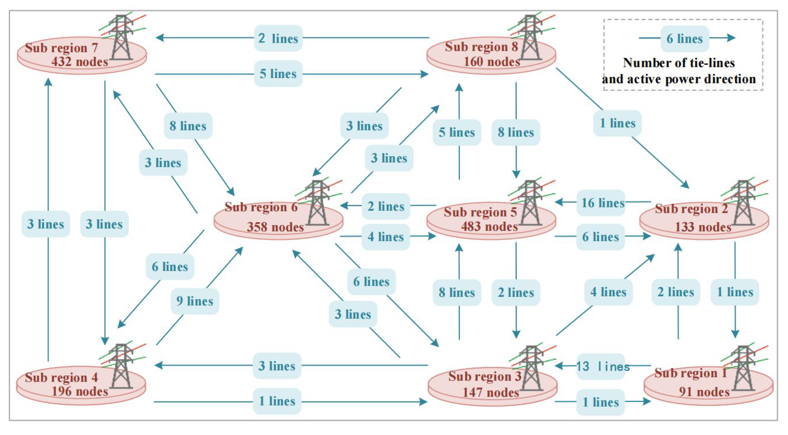
The three test systems cover 8, 16, and 31 geographical regions, respectively, with node scales ranging from the thousand-node level to the ten-thousand-node level. The generator types include multiple renewable and conventional generation units, and the voltage-level structures are complex, indicating strong engineering representativeness. Such a multi-scale test setting helps avoid conclusions based on a single network topology and supports a more comprehensive assessment of the proposed method. In addition, the gradual increase in network scale and regional coupling intensity can further reflect the computational challenges faced in practical large-scale grid analysis, especially when boundary information needs to be exchanged among multiple subregions. These differences in system size, regional partitioning, generation composition, and voltage hierarchy provide a suitable basis for evaluating the accuracy and scalability of the proposed framework under different operating conditions. In particular, the increasing number of regions and tie-line connections can better reflect the boundary-coupling characteristics of large-scale power grids. Taking the 2000-node system as an example, Figure 2 shows the number of subregions and the tie-line connections among them. The interregional connections of the other two systems can be obtained according to the system structure and power flow distribution and are therefore not repeated here. The scales and basic parameters of the three test systems are summarized in Table 4.
In addition, the pointwise relative error (Relative Error, RE) is adopted as the core evaluation index to quantitatively measure the difference between the calculation results obtained by the CDDP-BiCGSTAB framework and those obtained by the centralized direct solution method. It is defined as:
R E n = e n C D D P e n r e f e n r e f × 100 %
where e n C D D P denotes the CEF of node i calculated by the CDDP-BiCGSTAB framework, and e n r e f denotes the reference solution obtained by the centralized direct solution method.

3.2. Sensitivity Analysis and Parameter Selection

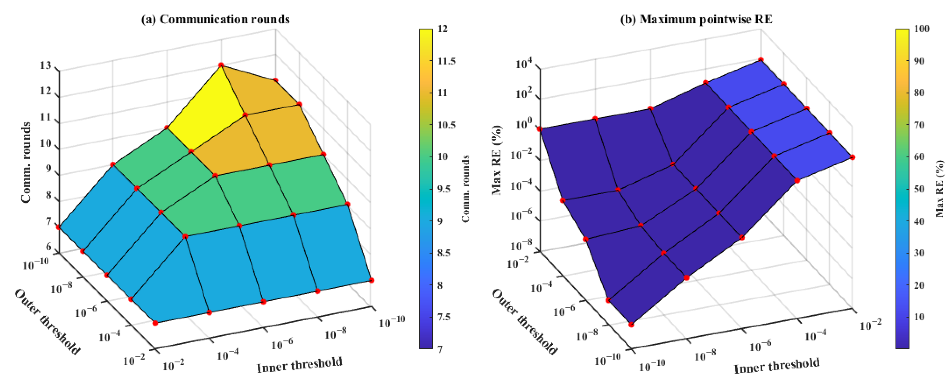
In fact, the overall computational performance of the CDDP-BiCGSTAB framework is jointly determined by the inner-layer convergence threshold and the outer-layer convergence threshold. The main parameters used in the proposed CDDP-BiCGSTAB calculation include the inner-layer convergence threshold, the outer-layer convergence threshold, the maximum number of inner BiCGSTAB iterations, the maximum number of outer iterations, and the initial-solution strategy. In the simulation program, the inner-layer convergence threshold is set to 1 × 10⁻⁸, and the outer-layer convergence threshold is set to 1 × 10⁻⁶. For each subregion, the maximum number of inner BiCGSTAB iterations is set to twice the dimension of the local coefficient matrix. The maximum number of outer iterations is set to the number of system nodes as a safeguard against non-convergence. In the first outer iteration, the initial solution is set to zero, while in subsequent outer iterations, the CEF solution from the previous outer iteration is used as the initial solution to accelerate convergence. To determine these two key parameters, the 2000-node system is taken as an example, and a grid search is conducted to test the effects of the inner- and outer-layer convergence thresholds on the number of outer iterations, namely the number of communication rounds, and the maximum value of the pointwise relative error. The results are shown in Figure 3. It is worth noting that the red dots in Figure 3 indicate the sampling points used for the sensitivity analysis through grid search.
As shown in Figure 3, looser settings of the inner- and outer-layer convergence thresholds lead to fewer communication rounds, but also result in larger pointwise relative errors. Therefore, considering both computational accuracy and communication rounds, the inner- and outer-layer convergence thresholds are set to 1 × 10⁻⁸ and 1 × 10⁻⁶, respectively. In practical engineering applications, these thresholds can be flexibly adjusted according to specific requirements.

3.3. Performance on the 2000-Node, 8-Region System

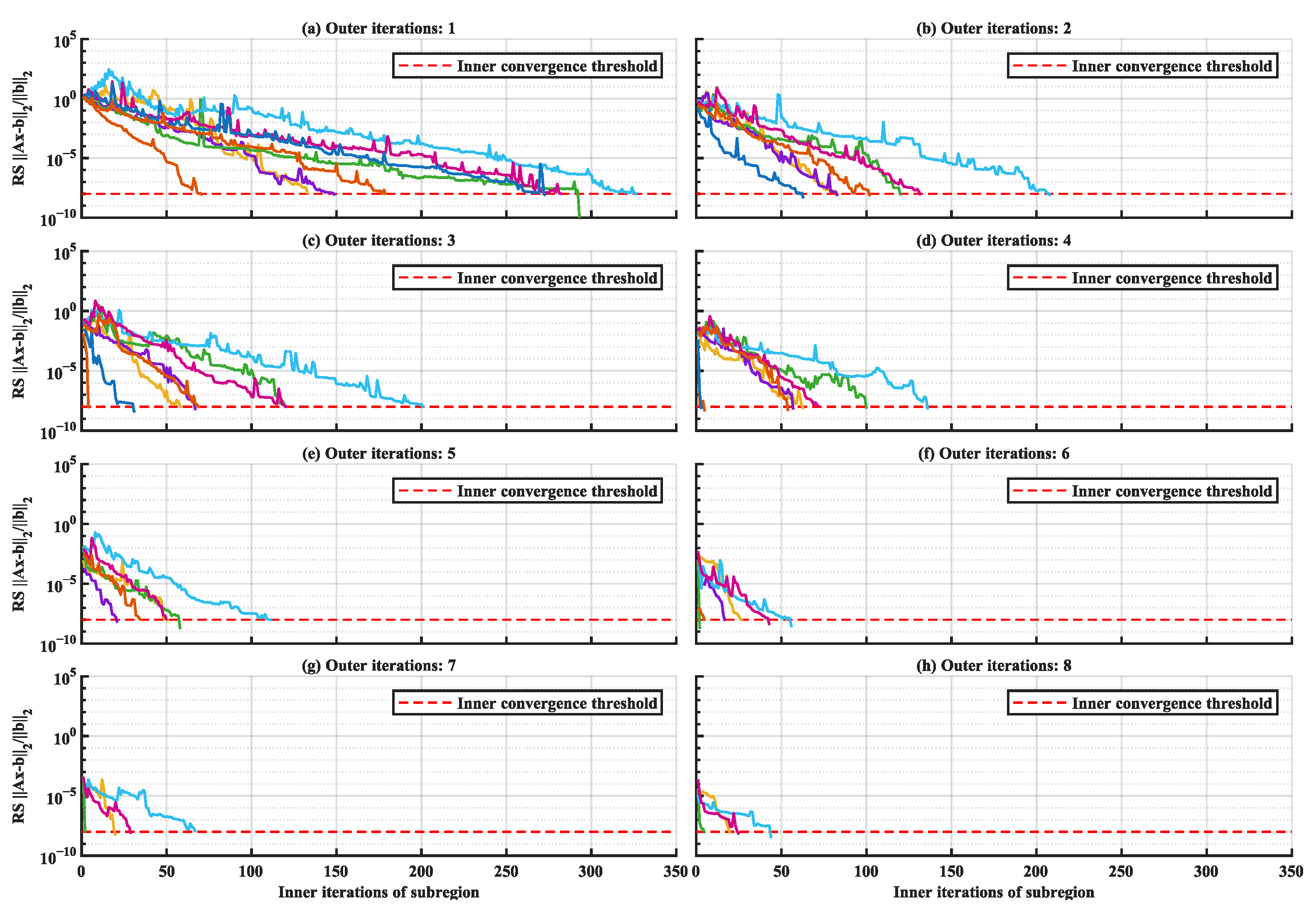
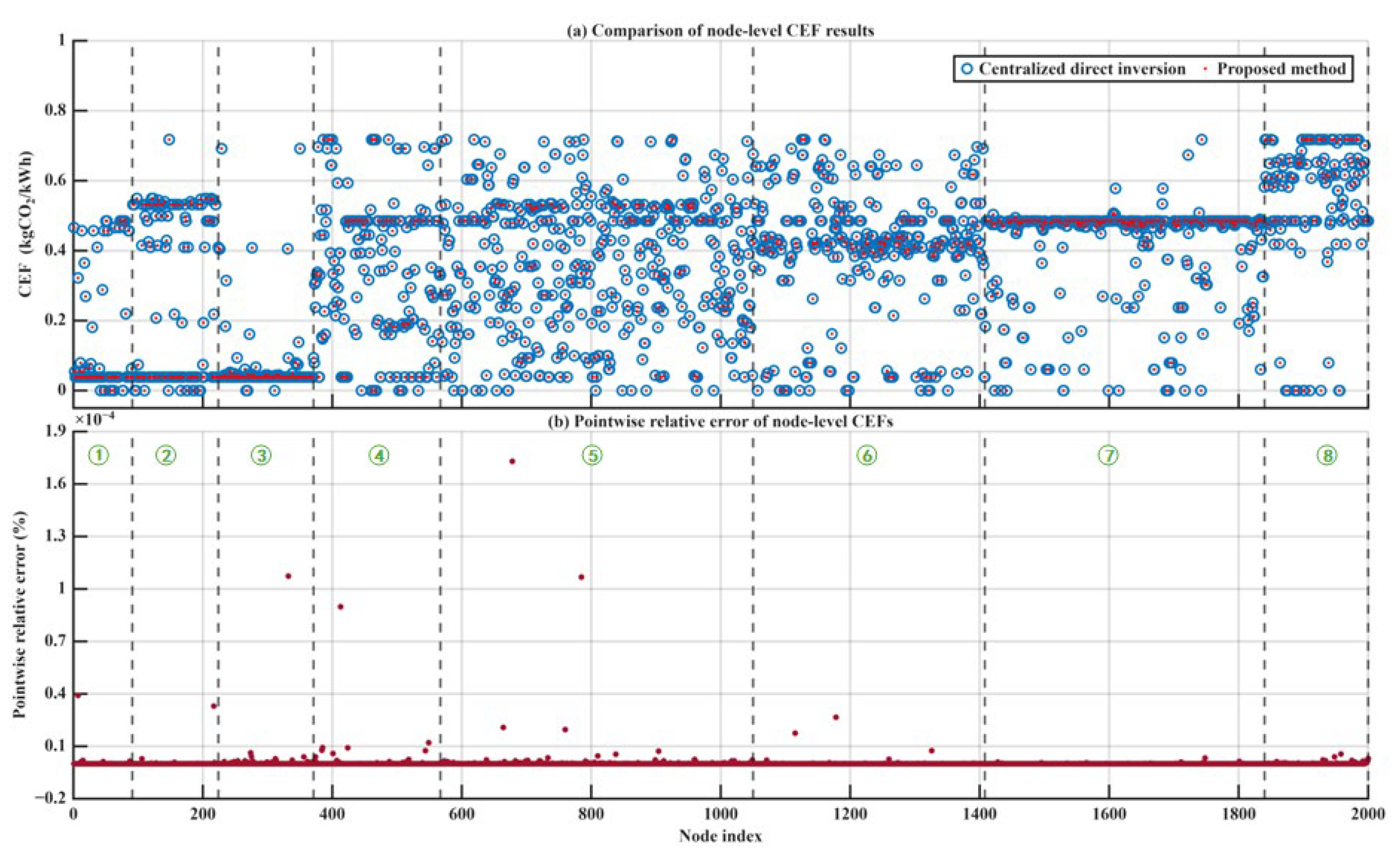
The performance of the CDDP-BiCGSTAB framework is further tested on the 2000-node, 8-region system. Figure 4 reports the inner- and outer-layer convergence behavior, and Figure 5 reports the node-level CEFs and pointwise relative errors.
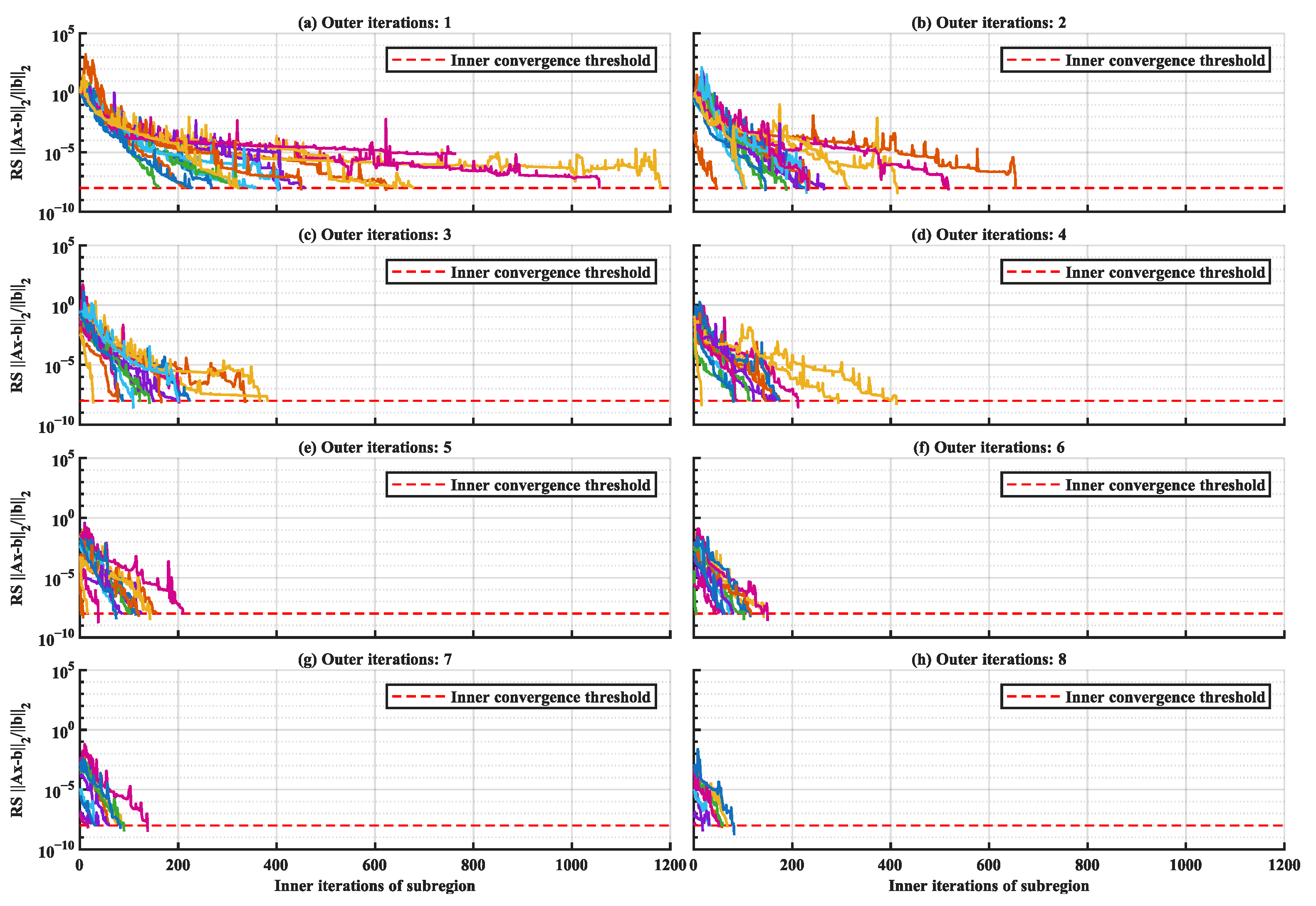
Figure 4 presents the inner- and outer-layer convergence behavior of the 2000-node, 8-region system within the first eight communication rounds. Each colored curve represents the relative residual of one subregion. It is worth noting that the different colors in Figure 4 represent the convergence curves of all subregions. All eight subregions converge to the specified outer-layer threshold, and as the outer iteration proceeds, the number of inner BiCGSTAB iterations required for convergence in each subregion gradually decreases.
Some local oscillation peaks appear in the convergence curves of certain subregions in Figure 4, which is an inherent characteristic of BiCGSTAB when solving sparse nonsymmetric matrices and does not affect the overall convergence of the algorithm.
Figure 5 reports the node-level CEFs and the pointwise relative errors of the 2000-node, 8-region system compared with the centralized direct solution. The left panel groups the CEF values by subregion, where the symbol on the x-axis denotes the subregion number; the right panel shows the relative error of every node. The relative errors of all nodes are within 0.00019%, confirming that the proposed framework preserves the accuracy of the centralized solution at the thousand-node scale.

3.4. Performance on the 10,000-Node, 16-Region System

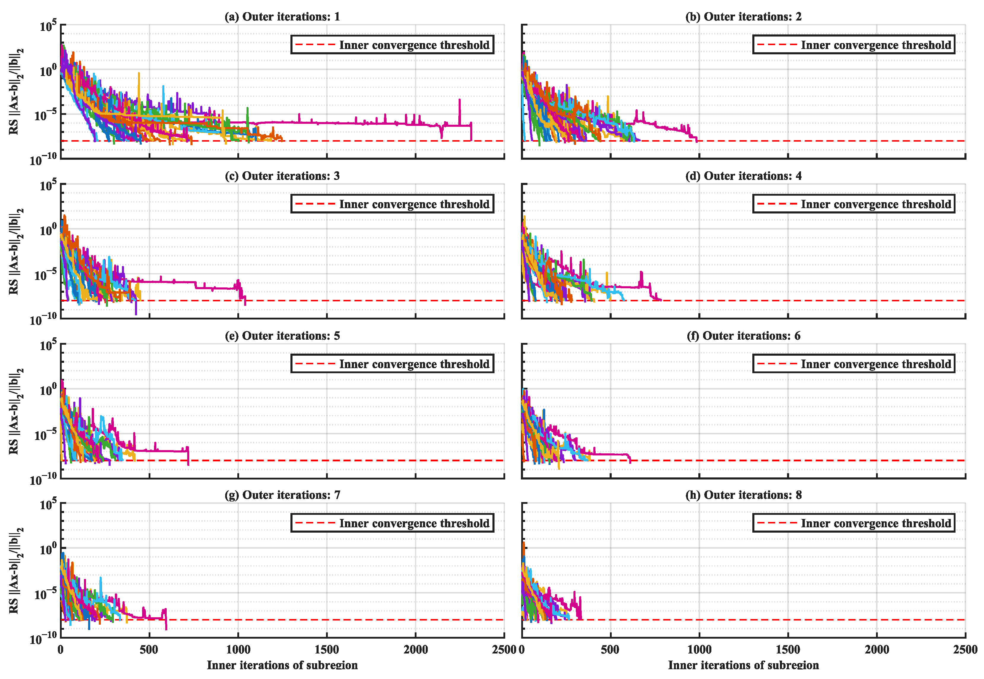
Figure 6 shows the convergence performance of the proposed framework on the 10,000-node, 16-region test system. It is worth noting that the different colors in Figure 6 represent the convergence curves of all subregions. Compared with the 2000-node system, each subregion requires noticeably more BiCGSTAB iterations in a single outer iteration, mainly due to the larger local equation systems and stronger boundary coupling with multiple opposite-side regions. Nevertheless, the convergence trajectories of all subregions still decrease to the prescribed threshold. In the early outer iterations, some subregions require more inner iterations because the exchanged boundary-node CEFs have not yet fully stabilized. After several communication rounds, the boundary information becomes more accurate, and the inner BiCGSTAB solver generally converges with fewer iterations. These results indicate that the warm-start strategy remains effective when the system scale increases to the ten-thousand-node level.
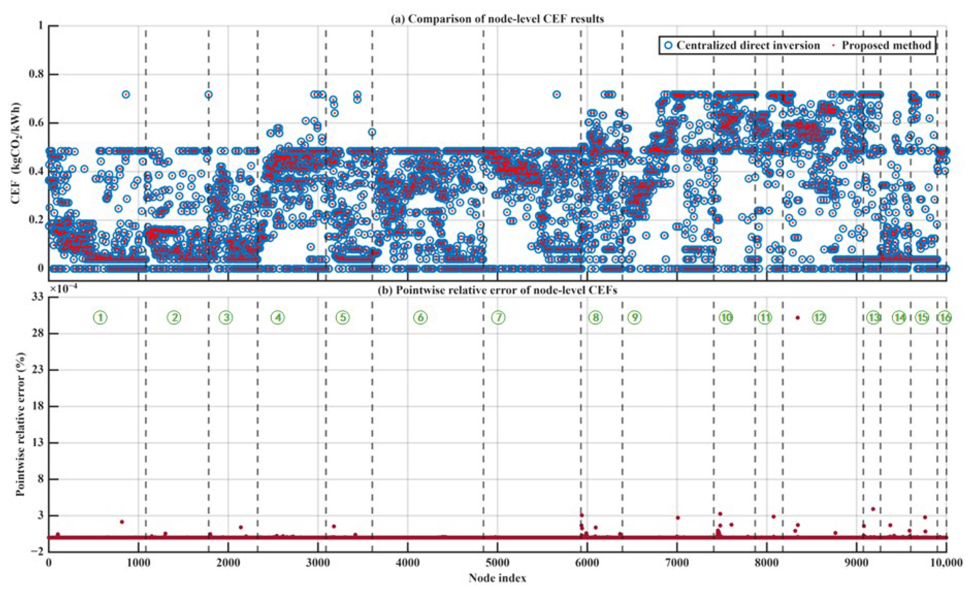
Figure 7 further compares the node-level CEFs obtained by the proposed method with those obtained by centralized direct inversion. The CEF profile remains consistent across different subregions, while the error distribution stays within a very small range. Except for one node in subregion 12, where the relative error is approximately 0.0030%, the relative errors of all other nodes are within 0.0004%. Therefore, the proposed CDDP-BiCGSTAB framework can maintain high numerical accuracy while extending the calculation scale from 2000 nodes to 10,000 nodes.

3.5. Performance on the 25,000-Node, 31-Region System

To further verify the effectiveness of the proposed framework in a larger-scale system, the 25,000-node, 31-region system is used for validation. Figure 8 illustrates the inner- and outer-layer convergence behavior of this system. It is worth noting that the different colors in Figure 8 represent the convergence curves of all subregions. When the result from the previous outer iteration is used as the initial solution, the inner-layer solution of subregional node-level CEFs still exhibits an acceleration effect. Specifically, as the outer iteration proceeds, the convergence of each subregion shows an overall accelerating trend. In the first outer iteration, all subregions require up to approximately 2500 BiCGSTAB iterations for the relative residual to reach the specified threshold, whereas in the second outer iteration, this value decreases to approximately 1000 iterations. Although the initial inner-layer iteration count is higher than those in the 2000-node and 10,000-node systems, no divergence is observed among the subregional convergence curves. After the first communication round, the updated boundary-node CEFs provide more accurate boundary conditions and a better initial solution for each subregion, which substantially reduces the number of BiCGSTAB iterations in subsequent outer iterations. This indicates that the centralized data distribution pattern can still coordinate boundary information effectively in a larger-scale partitioned system.
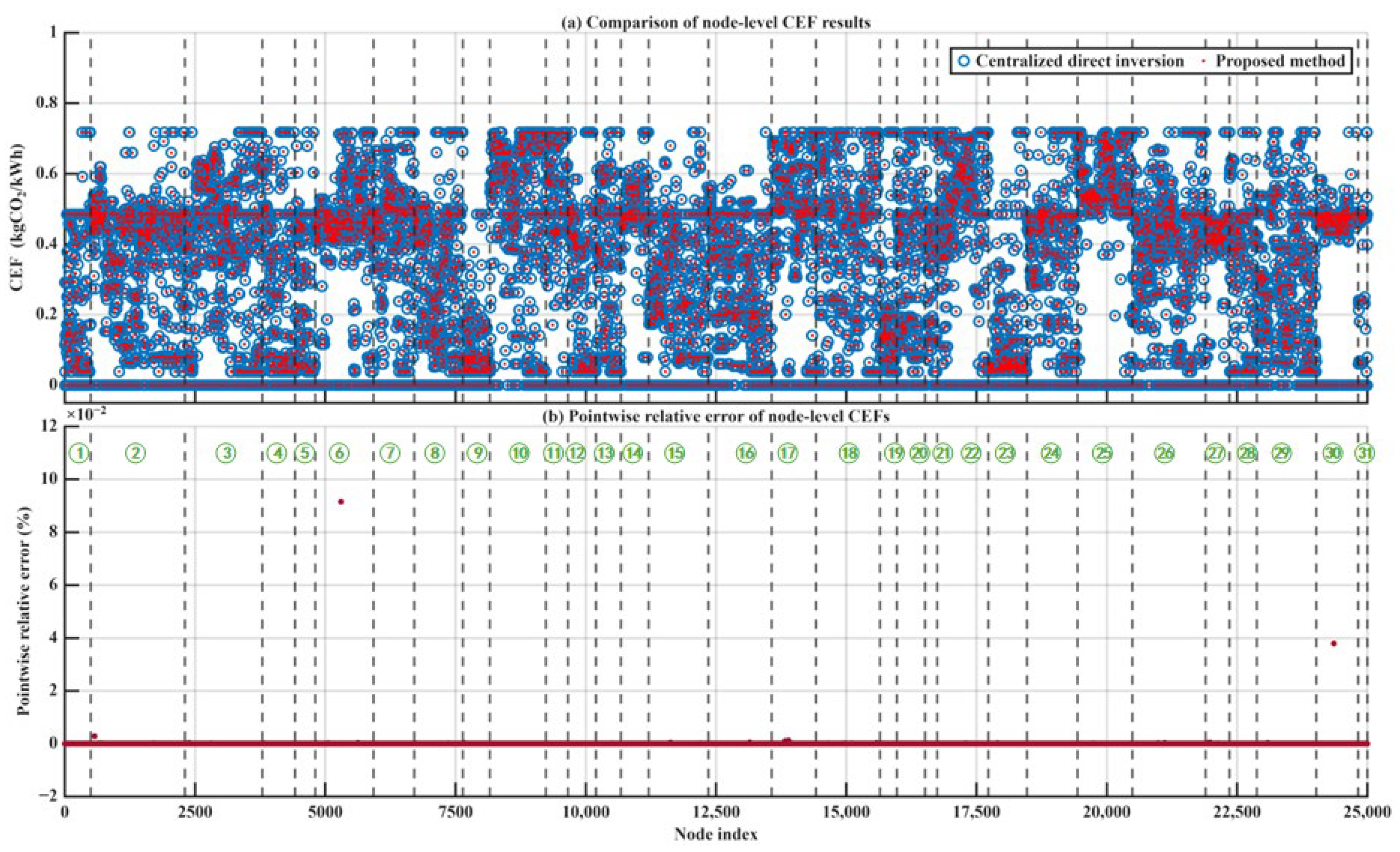
In addition, Figure 9 presents the node-level CEFs and pointwise relative errors. The maximum relative error of CEFs in the entire system is approximately 0.0900%, which is higher than the 0.0030% observed in the 10,000-node system. This is related to the larger number of boundary nodes and the longer cross-regional propagation paths in the 25,000-node system. Nevertheless, the accuracy satisfies practical engineering requirements and can be further improved by adjusting the inner- and outer-layer convergence thresholds.
It should be noted that the reported errors are calculated by comparing the proposed partitioned framework with the centralized direct inversion solution under the same input data. In this study, the centralized direct inversion solution refers to the CEFs of all nodes obtained by directly inverting the full-network CEF equation system. After isolated nodes are removed to ensure matrix invertibility, this direct inversion solution is regarded as the reference solution. Therefore, the errors reported in this paper represent the numerical discrepancies between the proposed partitioned iterative method and the centralized direct inversion method, rather than modeling errors or measurement errors. Specifically, the reported values are the maximum pointwise relative errors over all nodes, rather than average errors. Maintaining the maximum error below 0.1% in a 25,000-node system with 31 regions indicates that the proposed framework remains numerically consistent with the centralized reference solution even under large-scale regional coupling. In addition, the accuracy of the proposed iterative method can be adjusted through the inner- and outer-layer convergence thresholds. Tighter thresholds can further reduce the numerical errors, whereas looser thresholds can reduce the number of BiCGSTAB iterations and communication rounds. Therefore, the proposed framework can meet different practical requirements for calculation accuracy and computational efficiency.
This result supports the robustness of the proposed method for large-scale grid-level CEF calculation. The test results of the three systems jointly indicate that the proposed method has good scalability for efficient and accurate partitioned calculation of node-level CEFs in large-scale power grids. These errors can be further reduced by tightening the inner- and outer-layer convergence thresholds, but this would increase the number of BiCGSTAB iterations and communication rounds.
Table 5 provides a clearer numerical summary of the results presented in Figure 4, Figure 5, Figure 6, Figure 7, Figure 8 and Figure 9, including the test-system scale, number of regions, maximum relative error, and the main observation for each case.

4. Discussion

By decomposing the full-network carbon emission flow model into multiple subregional equation systems, the CDDP-BiCGSTAB framework avoids solving the entire system in a centralized manner and reduces the dependence on full-network data aggregation. Each region independently solves its local CEF calculation problem and only discloses boundary-node CEFs to the centralized broker, while internal generation parameters, load information, and branch power flow data remain within the region. Such a mechanism is consistent with the operational mode of unified dispatch and hierarchical management, and supports privacy-preserving CEF calculation in practical large-scale power grids. This consistency also indicates the immediate engineering applicability of the proposed framework: the centralized broker can be regarded as the dispatching or coordination entity, while each subregion corresponds to a regional grid operator that performs local calculation and only reports the required boundary-node CEFs.
The observed convergence behavior can be explained by the nested inner- and outer-layer iteration mechanism. At the inner layer, BiCGSTAB is used to solve the sparse and nonsymmetric CEF equation system within each subregion. At the outer layer, boundary-node CEFs are updated through the centralized broker. As the outer iteration proceeds, boundary CEFs gradually approach stable values, and the number of inner BiCGSTAB iterations generally decreases. This indicates that using the previous solution as the initial value is beneficial for accelerating inner-layer convergence.
Sensitivity results indicate that the convergence thresholds directly affect the trade-off between communication efficiency and calculation accuracy. Looser inner- and outer-layer thresholds reduce the number of communication rounds but increase the pointwise relative error. For the 25,000-node system, the higher maximum relative error is mainly associated with the larger number of boundary nodes and larger cross-regional propagation paths. Therefore, threshold settings should be adjusted in practical applications according to accuracy requirements, communication cost, and computational efficiency.
When comparing numerical errors with previous studies, a direct one-to-one comparison is not straightforward because the test systems, reference solutions, and error definitions are different. Existing studies on nodal CEF calculation and carbon emission flow analysis mainly focus on centralized formulations or application-oriented dispatch and energy-management problems in small- and medium-scale systems. In this study, the centralized method refers to direct inversion of the full-network CEF equation system to obtain the CEFs of all nodes. After isolated nodes are removed to ensure the invertibility of the system matrix, the centralized direct inversion solution is regarded as the reference solution. Therefore, the reported errors represent the numerical discrepancies between the proposed partitioned iterative method and the centralized direct inversion method under the same input data. The maximum pointwise relative errors are 0.00019%, 0.0030%, and 0.0900% for the 2000-node, 10,000-node, and 25,000-node systems, respectively. These results indicate that the proposed framework remains numerically consistent with the centralized reference solution while extending nodal CEF calculation to larger-scale partitioned power systems. In addition, the accuracy of the proposed iterative method can be adjusted through the inner- and outer-layer convergence thresholds. Tighter thresholds can further reduce the numerical errors, whereas looser thresholds can reduce communication rounds and computational costs, allowing the framework to meet different practical accuracy and efficiency requirements.
Several practical limitations should also be noted. First, the communication process between subregional computing centers and the centralized broker is assumed to be reliable and synchronized in this study. In practical communication networks, latency may increase the waiting time before each outer-layer update, while packet loss may delay or interrupt the delivery of boundary-node CEFs, thereby affecting the convergence speed of the outer iteration. Since CEF calculation fundamentally relies on the completeness of the required data, communication latency or packet loss that causes data incompleteness may make valid CEF computation infeasible for all existing CEF calculation methods, including the proposed framework. However, the focus of this study is to address data privacy and computational organization issues in conventional centralized CEF calculation, while communication-induced data missing is beyond the scope of the present work. In practice, such problems can be reduced or even avoided by enhancing the robustness of power-system data communication networks. The forward-looking issue raised by the reviewer will also be discussed as an important direction for future work. Since CEF calculation fundamentally relies on the completeness of the required data, communication latency or packet loss that causes data incompleteness may make valid CEF computation infeasible for all existing CEF calculation methods, including the proposed framework. However, the focus of this study is to address data privacy and computational organization issues in conventional centralized CEF calculation, while communication-induced data missing is beyond the scope of the present work. In practice, such problems can be reduced or even avoided by enhancing the robustness of power-system data communication networks. The forward-looking issue raised by the reviewer will also be discussed as an important direction for future work. Second, the proposed framework is based on a fixed network topology and a fixed power-flow snapshot during one CEF calculation task. For highly dynamic switching operations or real-time fault reconfigurations, the subregional matrices and boundary-data templates need to be updated or reconstructed accordingly. Nevertheless, once the network topology has been determined, the proposed method remains applicable. It should be noted that this assumption does not restrict the applicability of the proposed method to a specific topology. Once the network topology is determined, the proposed framework remains valid and can be applied by regenerating the corresponding subregional matrices and boundary information. Third, the star-shaped communication topology relies on the centralized broker, which may introduce a potential single point of failure. In practical deployment, redundant brokers, hierarchical broker architectures, or distributed-ledger-based verification mechanisms can be considered to improve reliability and traceability.
These limitations also indicate that future work should further investigate communication-aware convergence analysis, dynamic topology updating, and more reliable broker architectures for practical deployment in large-scale power systems.

5. Conclusions

This paper proposes a partitioned iterative framework for calculating node-level carbon emission factors in large-scale power systems, based on a centralized data distribution pattern and the BiCGSTAB algorithm. To address the computational burden and data privacy constraints associated with conventional centralized methods, the proposed framework decomposes the full-network carbon emission flow model into multiple subregional equation systems. Within this framework, each regional operator only solves its local CEF calculation problem and transmits the CEFs of boundary nodes to the centralized broker, while internal generation parameters, load information, and branch power-flow data are retained locally and remain protected.
Validation is performed on three large-scale test systems, namely the 2000-node, 8-region system, the 10,000-node, 16-region system, and the 25,000-node, 31-region system. Compared with the centralized direct solution, the maximum relative errors of node-level CEFs are 0.00019%, 0.0030%, and 0.0900%, respectively. These results demonstrate that the proposed CDDP-BiCGSTAB framework maintains high calculation accuracy across different system scales and shows good scalability for large-scale power grid applications.
Overall, the proposed method achieves a balance among calculation accuracy, scalability, and data privacy protection. The main novelty of this work lies in integrating the CDDP-based boundary information coordination with the BiCGSTAB-based subregional solution, which enables node-level CEF calculation to be extended from conventional centralized settings to large-scale partitioned power systems. It provides an engineering-oriented solution for node-level CEF calculation in large-scale new-type power systems and supports potential applications in indirect carbon emission accounting, demand-side carbon management, and low-carbon dispatch decision-making. Future work can further extend the proposed partitioned iterative framework in several directions. First, the efficient handling of boundary-node information can be combined with long-term grid planning models to examine how storage technologies and smart-grid technologies under decision-dependent uncertainty may affect regional carbon emission flow analysis [26,27]. Second, with the rapid development of transportation electrification, smart EV charging and vehicle-to-grid flexibility can be incorporated to reflect their impact on nodal CEFs under dynamic load conditions [28]. Third, renewable-energy expansion and its land-use constraints can be considered in future carbon emission flow studies to improve the realism of long-term low-carbon grid planning [29]. In addition, recent studies on the day-ahead optimization of interconnected power systems and net-zero-carbon emission pathway planning can provide useful references for linking nodal CEF calculation with low-carbon operation and long-term emission-reduction strategies [30,31]. Finally, distributed ledger technologies, such as blockchain, can be integrated to enhance the security, traceability, and credibility of boundary-data transmission among regions.

Author Contributions

The authors confirm their contributions to the paper as follows: Conceptualization, Y.C. and R.C.; methodology, Y.C. and R.C.; software, Y.C. and H.J.; validation, Y.C., H.J. and Y.H.; formal analysis, Y.C. and R.C.; investigation, H.J. and Y.H.; resources, F.Z.; data curation, H.J. and Y.H.; writing—original draft preparation, Y.C.; writing—review and editing, R.C. and F.Z.; visualization, Y.C. and H.J.; supervision, F.Z.; project administration, F.Z. All authors have read and agreed to the published version of the manuscript.

Funding

This research received no external funding.

Institutional Review Board Statement

Not applicable.

Informed Consent Statement

Not applicable.

Data Availability Statement

The benchmark system data used in this study are publicly available from the ACTIVSg synthetic power grid test case library [25]. The derived calculation results supporting the findings of this study are available within the article. Further supporting data are available from the corresponding author upon reasonable request.

Conflicts of Interest

All the authors were employed by the company China Southern Power Grid Artificial Intelligence Technology Co., Ltd.

Abbreviations

The following abbreviations are used in this manuscript:
CEFCarbon emission factor
CDDPCentralized data distribution pattern
CBCentralized broker
BiCGSTABBiconjugate gradient stabilized algorithm
RERelative error

References

  1. Zhu, S.; Ji, J.; Huang, Q.; Li, S.; Ren, J.; He, D.; Yang, Y. Optimal scheduling and trading in joint electricity and carbon markets. Energy Strategy Rev. 2024, 54, 101426. [Google Scholar] [CrossRef]
  2. Yang, C.; Liu, J.; Liao, H.; Liang, G.; Zhao, J. An improved carbon emission flow method for the power grid with prosumers. Energy Rep. 2023, 9, 114–121. [Google Scholar] [CrossRef]
  3. Park, B.; Dong, J.; Liu, B.; Kuruganti, T. Decarbonizing the grid: Utilizing demand-side flexibility for carbon emission reduction through locational marginal emissions in distribution networks. Appl. Energy 2023, 330, 120303. [Google Scholar] [CrossRef]
  4. Wang, Y.; Qiu, J.; Tao, Y.; Zhao, J. Carbon-oriented operational planning in coupled electricity and emission trading markets. IEEE Trans. Power Syst. 2020, 35, 3145–3157. [Google Scholar] [CrossRef]
  5. Chen, X.; Chao, H.; Shi, W.; Li, N. Towards carbon-free electricity: A flow-based framework for power grid carbon accounting and decarbonization. Energy Convers. Econ. 2024, 5, 396–418. [Google Scholar] [CrossRef]
  6. Kang, C.; Zhou, T.; Chen, Q.; Wang, J.; Sun, Y.; Xia, Q.; Yan, H. Carbon emission flow from generation to demand: A network-based model. IEEE Trans. Smart Grid 2015, 6, 2386–2394. [Google Scholar] [CrossRef]
  7. Cheng, Y.; Zhang, N.; Zhang, B.; Kang, C.; Xi, W.; Feng, M. Low-carbon operation of multiple energy systems based on energy-carbon integrated prices. IEEE Trans. Smart Grid 2019, 11, 1307–1318. [Google Scholar] [CrossRef]
  8. Cheng, Y.; Zhang, N.; Wang, Y.; Yang, J.; Kang, C.; Xia, Q. Modeling carbon emission flow in multiple energy systems. IEEE Trans. Smart Grid 2018, 10, 3562–3574. [Google Scholar] [CrossRef]
  9. Li, B.; Song, Y.; Hu, Z. Carbon flow tracing method for assessment of demand side carbon emissions obligation. IEEE Trans. Sustain. Energy 2013, 4, 1100–1107. [Google Scholar] [CrossRef]
  10. Wang, Y.; Qiu, J.; Tao, Y. Optimal power scheduling using data-driven carbon emission flow modelling for carbon intensity control. IEEE Trans. Power Syst. 2021, 37, 2894–2905. [Google Scholar] [CrossRef]
  11. Sang, L.; Xu, Y.; Sun, H. Encoding carbon emission flow in energy management: A compact constraint learning approach. IEEE Trans. Sustain. Energy 2023, 15, 123–135. [Google Scholar] [CrossRef]
  12. Chen, X.; Sun, A.; Shi, W.; Li, N. Carbon-aware optimal power flow. IEEE Trans. Power Syst. 2024, 40, 3090–3104. [Google Scholar] [CrossRef]
  13. Chen, W.; Liu, G.P. Privacy-preserving consensus-based distributed economic dispatch of smart grids via state decomposition. IEEE/CAA J. Autom. Sin. 2024, 11, 1250–1261. [Google Scholar] [CrossRef]
  14. Zimmerman, R.D.; Murillo-Sanchez, C.E.; Thomas, R.J. MATPOWER: Steady-state operations, planning, and analysis tools for power systems research and education. IEEE Trans. Power Syst. 2010, 26, 12–19. [Google Scholar] [CrossRef]
  15. Van der Vorst, H.A. Bi-CGSTAB: A fast and smoothly converging variant of Bi-CG for the solution of nonsymmetric linear systems. SIAM J. Sci. Stat. Comput. 1992, 13, 631–644. [Google Scholar] [CrossRef]
  16. Erseghe, T. Distributed optimal power flow using ADMM. IEEE Trans. Power Syst. 2014, 29, 2370–2380. [Google Scholar] [CrossRef]
  17. Mhanna, S.; Verbic, G.; Chapman, A.C. Adaptive ADMM for distributed AC optimal power flow. IEEE Trans. Power Syst. 2018, 34, 2025–2035. [Google Scholar] [CrossRef]
  18. An, W.; Ding, D.; Wang, Z.; Liu, Q.; Dong, H. Privacy-preserving distributed optimization for economic dispatch in smart grids. Automatica 2025, 177, 112275. [Google Scholar] [CrossRef]
  19. Sun, L.; Ding, D.; Dong, H.; Bai, X. Privacy-preserving distributed economic dispatch for microgrids based on state decomposition with added noises. IEEE Trans. Smart Grid 2023, 15, 2424–2433. [Google Scholar] [CrossRef]
  20. Bu, L.; Chen, X.; Gan, L.; Yu, K.; Zhou, Y.; Cao, J.; Cao, Y. Low-carbon operation method of the building based on dynamic carbon emission factor of power system. IET Smart Grid 2023, 6, 67–85. [Google Scholar] [CrossRef]
  21. Zhang, X.; Guo, Z.; Pan, F.; Yang, Y.; Li, C. Dynamic carbon emission factor based interactive control of distribution network by a generalized regression neural network assisted optimization. Energy 2023, 283, 129132. [Google Scholar] [CrossRef]
  22. Guo, Z.; Zhang, X.; Pan, F.; Yang, Y.; Li, J. Dynamic electricity-carbon factors driven fast day-ahead coordination and optimization of source-load-storage in distribution networks with a white box accelerator. Energy 2025, 331, 137049. [Google Scholar] [CrossRef]
  23. Liu, Z.; Guan, D.; Wei, W.; Davis, S.J.; Ciais, P.; Bai, J.; Peng, S.; Zhang, Q.; Hubacek, K.; Marland, G.; et al. Reduced carbon emission estimates from fossil fuel combustion and cement production in China. Nature 2015, 524, 335–338. [Google Scholar] [CrossRef] [PubMed]
  24. Shan, Y.; Liu, J.; Liu, Z.; Xu, X.; Shao, S.; Wang, P.; Guan, D. New provincial CO2 emission inventories in China based on apparent energy consumption data and updated emission factors. Appl. Energy 2016, 184, 742–750. [Google Scholar] [CrossRef]
  25. Texas A&M University. Electric Grid Test Cases. Available online: https://electricgrids.engr.tamu.edu/electric-grid-test-cases/ (accessed on 9 April 2026).
  26. Giannelos, S.; Konstantelos, I.; Strbac, G. A new class of planning models for option valuation of storage technologies under decision-dependent innovation uncertainty. In Proceedings of the 2017 IEEE Manchester PowerTech, Manchester, UK, 18–22 June 2017; pp. 1–6. [Google Scholar] [CrossRef]
  27. Amann, G.; Escobedo Bermúdez, V.R.; Boskov-Kovacs, E.; Gallego Amores, S.; Giannelos, S.; Iliceto, A.; Ilo, A.; Chavarro, J.R.; Samovich, N.; Schmitt, L.; et al. E-Mobility Deployment and Impact on Grids: Impact of Electric Vehicle and Charging Infrastructure on European Transmission and Distribution Grids: Innovation Needs; Publications Office of the European Union: Luxembourg, 2022. [Google Scholar] [CrossRef]
  28. Koutsandreas, D.; Ardehali, A.; Giannelos, S.; Pudjianto, D. Quantifying the trade-offs between clean-energy expansion and land requirements: Evidence from Greece. Energies 2026, 19, 2261. [Google Scholar] [CrossRef]
  29. Giannelos, S. Option Valuation of Smart Grid Technology Projects Under Endogenous and Exogenous Uncertainty. Ph.D. Thesis, Imperial College London, London, UK, 2016. [Google Scholar]
  30. Malamaki, K.-N.D.; Fotopoulou, M.; Martinez-Lopez, D.; Lampsidis, G.; Ferrer-Fernandez, P.; Andriopoulos, N.; Tzanis, N.; Kaousias, K.; Chassioti, E.; Moraitis, I. Day ahead optimization of insular systems considering future interconnection: The case of Ikaria island. Sustain. Energy Grids Netw. 2025, 44, 102018. [Google Scholar] [CrossRef]
  31. Liu, J.; Li, J.W.; Li, X.; Li, Y.P.; Gao, P.P.; Jin, L. An optimization model to provide electric power systems’ net zero-carbon emission pathways considering diverse measures under double-side randomness and vagueness. Renew. Energy 2026, 256, 124637. [Google Scholar] [CrossRef]
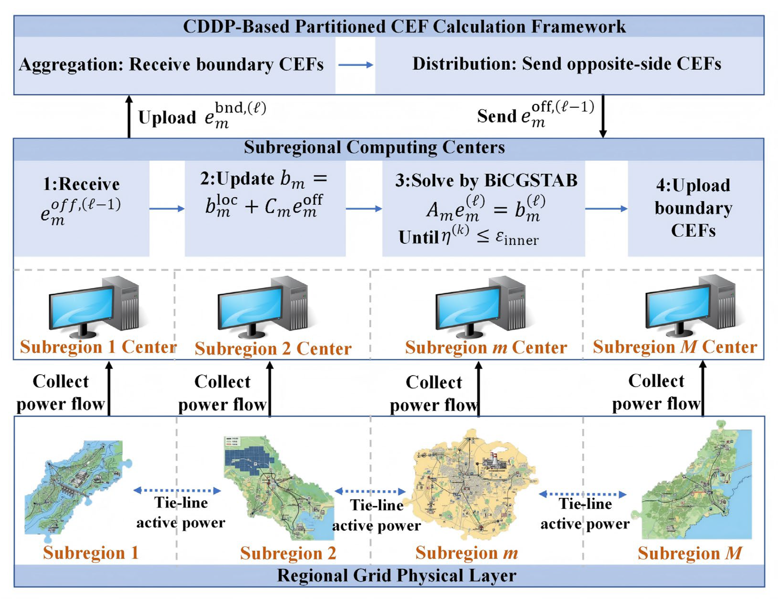
Figure 1. Partitioned calculation framework for node-level carbon emission factors based on the centralized data distribution pattern (CDDP). Each numbered block in the figure represents one subregion, indexed by m = 1, 2, …, M, and the central block represents the centralized broker (CB) that coordinates boundary information exchange.
Technologies 14 00420 g001
Figure 2. Interregional tie-line connections in the 2000-node, 8-region system.
Technologies 14 00420 g002
Figure 3. Sensitivity analysis results for inner- and outer-layer convergence thresholds.
Technologies 14 00420 g003
Figure 4. Inner- and outer-layer convergence behavior of the 2000-node, 8-region system.
Technologies 14 00420 g004
Figure 5. Node-level CEFs and pointwise relative errors in the 2000-node, 8-region system.
Technologies 14 00420 g005
Figure 6. Inner- and outer-layer convergence behavior of the 10,000-node, 16-region system.
Technologies 14 00420 g006
Figure 7. Node-level CEFs and pointwise relative errors in the 10,000-node, 16-region system.
Technologies 14 00420 g007
Figure 8. Inner- and outer-layer convergence behavior of the 25,000-node, 31-region system.
Technologies 14 00420 g008
Figure 9. Node-level CEFs and pointwise relative errors in the 25,000-node, 31-region system.
Technologies 14 00420 g009
Table 1. Comparison of the proposed CDDP-BiCGSTAB framework with representative existing CEF methods.
Ref.MethodPartitioned CalculationMax. Scale (Nodes/Regions)
[6]Centralized carbon emission flowNo<1000/–
[7]Centralized multi-energy carbon emission flowNo<1000/–
[10]Data-driven Bayesian carbon emission flowNo<1000/–
[12]Carbon-aware OPF with nodal carbon intensityNo<1000/–
[21]Demand-side low-carbon energy management with nodal CEFNo<1000/–
This workPartitioned CDDP-BiCGSTABYes (subregional sparse nonsymmetric BiCGSTAB)25,000/31
Table 2. Nomenclature of main symbols used in the methodology.
SymbolDescriptionUnit
e Node-level CEF vector of the full networkkgCO2/kWh
e n CEF of node nkgCO2/kWh
ε g , n CEF of generator g connected to node nkgCO2/kWh
P g , n Active power output of generator g connected to node nkW
U n Set of upstream nodes injecting active power into node n-
f j n Active power injected into node n through branch (j-n)kW
A Coefficient matrix of the full-network CEF equationkW
b Constant vector of the full-network CEF equationkgCO2/h
R m Node set of subregion m-
N m Number of nodes in subregion m-
R m b n d Set of boundary nodes in subregion m-
O m Set of opposite-side nodes injecting power into subregion m-
A m Coefficient matrix of subregion mkW
e m Node-level CEF vector of subregion mkgCO2/kWh
b m Constant vector of subregion mkgCO2/h
C m Boundary coupling matrix of subregion mkW
e m o f f CEF vector of opposite-side nodes for subregion mkgCO2/kWh
η k Inner-layer relative residual-
ε i n n e r Inner-layer convergence threshold-
δ l Boundary convergence error at the l-th outer iterationkgCO2/kWh
ε o u t e r Outer-layer convergence thresholdkgCO2/kWh
R E Pointwise relative error%
Table 3. Carbon emission factor parameters of different generator types.
Generator Type ε g , n (kgCO2/kWh)
Coal-fired power0.7180
Oil-fired power0.8390
Natural gas0.4850
Hydropower0.0380
Photovoltaic power0.0790
Wind power0.0380
Nuclear power0.0600
Table 4. Scales and basic parameters of the test systems.
Test
System
NodesBranchesGeneratorsRegionsGenerator TypesVoltage Levels (kV)System
Description
ACTIVSg 2000200032064328Gas, Hydro, Nuclear, PV, Coal, Wind500, 230, 161, 115, 24, 22, 20, 18, 13.8, 13.2Synthetic grid for Texas, USA
ACTIVSg 10k10,00012,706193716Gas, Hydro, Nuclear, PV, Coal, Wind765, 500, 345, 230, 161, 138, 115, 24, 22, 20, 18, 13.8, 13.2, 1Synthetic grid for the western USA
ACTIVSg 25k25,00032,230377931Gas, Hydro, Nuclear, PV, Coal, Wind, Oil765, 500, 345, 230, 161, 138, 115, 100, 69, 24, 22, 20, 18, 13.8, 13.2, 1Synthetic grid for the northeastern USA
Table 5. Summary of the main numerical results of the three test systems.
Test SystemNodesRegionsMax. Relative Error (%)Main Observation
ACTIVSg 2000200080.00019Accurate agreement with the centralized direct solution
ACTIVSg 10k10,000160.0030Accuracy maintained at the ten-thousand-node scale
ACTIVSg 25k25,000310.0900Maximum error remains below 0.1% under large-scale regional coupling
Disclaimer/Publisher’s Note: The statements, opinions and data contained in all publications are solely those of the individual author(s) and contributor(s) and not of MDPI and/or the editor(s). MDPI and/or the editor(s) disclaim responsibility for any injury to people or property resulting from any ideas, methods, instructions or products referred to in the content.