Article

Low-Cost Active Cell Balancing Battery Management System for Electric Vehicles with Cell Charger as Cell Balancer


1
Electrical Engineering Department, University of Indonesia, Kampus UI, Depok 16424, Indonesia
2
Research Center for Advanced Vehicle, University of Indonesia, Kampus UI, Depok 16424, Indonesia
3
Research Centre for Transportation Technology, National Research and Innovation Agency (BRIN), Bandung 40135, Indonesia
*
Author to whom correspondence should be addressed.
Technologies 2026, 14(5), 298; https://doi.org/10.3390/technologies14050298
Submission received: 16 March 2026 / Revised: 27 April 2026 / Accepted: 6 May 2026 / Published: 12 May 2026

Abstract

Cell imbalance in battery packs can cause premature termination during battery discharge and recharge processes. This condition can decrease the usable energy of the battery. The cost of batteries can reach 30–40% of the price of an electric vehicle, so battery cell balancing in a battery management system (BMS) and a battery thermal management system (BTMS) is very important to maximize battery capacity, safety, and life. In conventional active balancing studies, the cell-balancing process draws energy from the cells or battery pack, resulting in a reduction in battery pack energy due to power losses during the balancing process. This condition can reduce the range of electric vehicles. In this paper, a battery balancing system with a reduced number of switches and low cost, as well as the use of a cell charger, is proposed. The cell charger will draw energy from the electrical grid so that it can maximize the energy in the battery pack. A balancing current of 3 A from the cell charger is used in the balancing process. A 23S1P 100 Ah LiFePO4 battery pack, consisting of 23 cells, is used for validation. Test results show that the proposed battery balancing system can balance the voltage of 23 battery cells for 40 minutes from the highest and lowest voltage difference of 116.7 mV to 11.8 mV.

1. Introduction

The transportation sector is one of the sectors that contributes significantly to pollution worldwide. The use of electric vehicles (EVs) is considered important to reduce pollution from internal combustion engine vehicles (ICEVs). Types of EVs, such as plug-in hybrid electric vehicles (PHEVs), hybrid electric vehicles (HEVs), and battery electric vehicles (BEVs), all depend on energy storage systems (ESS). The ESS’s capabilities have a big impact on these vehicles’ performance. Because of their high energy density and extended service life, lithium batteries have drawn attention as an energy source for EVs in recent years. Lithium batteries are essential to EVs’ performance, especially when it comes to calculating the vehicles’ operating range. In EVs, batteries constitute the largest share of the cost, accounting for 30–40% of the total [1]. Although these batteries offer high energy density, they still experience degradation during their operational life. Frequent high-rate charging and discharging during EV operation can accelerate battery capacity degradation, lowering vehicle range, increasing replacement costs, and the possibility of thermal runaway [2,3,4].
Series or series-parallel battery cell configurations are necessary to increase the capacity and voltage in EVs. In battery packs, each battery cell is not made exactly the same. Even new batteries of the same type and model still have slight differences in capacity, internal resistance, self-discharge, and aging phenomena [5]. It is impossible to totally prevent small variations in battery cell capacity, even with careful cell selection. As a result, each time the battery is discharged or charged, each cell’s state of charge (SoC) will be slightly out of balance [6,7]. Negative consequences of cell imbalance in battery packs include early discharging and charging process termination, which can lower usable energy and shorten battery life [8,9,10]. Cell balancing will be implemented via a battery management system (BMS) in order to avoid this issue [11].
Various methods to reduce cell imbalance have been extensively researched. These methods can be broadly categorized into two types: passive and active [12,13,14]. The passive method is performed by releasing energy from the battery cells with higher voltage, thereby balancing the voltage of all cells to the lowest cell voltage [15,16]. This approach has two significant disadvantages despite its inexpensive cost, ease of use, and superior balancing performance. First, because of its temperature management system, this approach typically results in unfavorable side effects. As a result, the battery pack might need an extra thermal management system, adding to the system’s overall weight. Second, energy loss while balancing makes it impossible to accomplish the goal of energy conservation [8,17].
Active balancing, in contrast to ineffective passive techniques, uses a variety of balancing techniques to move energy from cells with greater voltage to cells with lower voltage, such as transformer-based balancing [18,19], inductor-based balancing [20], capacitor-based balancing [21,22], converter-based balancing [23,24], and a reconfigurable balancing method [25,26]. The effectiveness of active battery balancing systems in moving energy from stronger cells to weaker cells instead of dissipating it as heat is well known. Nevertheless, there are a number of serious disadvantages to this sophisticated functionality, one of which is its high price [27]. To be used in EVs and to compete with the price of passive battery balancing systems, a low-cost active battery balancing system design is crucial.
Previously, a low-cost active battery balancing device was also suggested. To transmit energy from high-voltage cells to low-voltage cells, Pham et al. [28] suggested a quick and inexpensive cell-to-cell balancing system that uses a single isolated push–pull converter. To reduce expenses, a switch arrangement is utilized to choose which battery cell pairs need to be balanced using relays. Twelve small-capacity battery cells connected in series were used in an experiment to verify the suggested method. Relays are inexpensive, but they have a limited service life due to physical wear on moving parts and contact issues, where frequent switching can result in arcing, corrosion, and eventually welding or contact failure. Unlike Pham et al. [28], Sun et al. [29] and Dinh et al. [30] used a MOSFET-based bidirectional switch to replace the relay in the switch array. In [29], Sun et al. proposed a hybrid battery balancing system using passive and active balancing systems with the same balancing circuit, making it simpler and less expensive. The proposed passive balancing system uses a heater, cooling fan, or resistor, while the active balancing system uses an isolated charger connected to a 12 V battery. The proposed method uses a bidirectional switch with a number of switches equal to 2n, where n is the number of battery cells connected in series. The bidirectional switches used are based on two MOSFETs with a common source configuration, where N-channel MOSFETs are used except for the two switches connected to the top battery cells, which use P-channel MOSFETs. A bidirectional switch is also used by Dinh et al. [30] in their proposed battery balancing system. A high-efficiency, low-cost cell-to-cell balancing system using a two-way CLLC resonant converter is proposed to transfer energy from high-voltage cells to low-voltage cells for 12 battery cells divided into two legs. The bidirectional switch in the switch arrangement used is only n + 2 plus two three-pole switches. The bidirectional switch used is also based on two MOSFETs with a common source configuration, where N-channel MOSFETs are used in each leg, except for the two switches connected to the top battery cell, which use P-channel MOSFETs.
In terms of the energy source used for balancing, cell balancing can be classified into cell balancing systems that use energy sources from cells/modules/battery packs and balancing systems that use energy sources from outside cells/modules/battery packs, as shown in Figure 1. The energy required for the balancing process in traditional active balancing research typically originates from the battery pack’s stored energy. The major drawback of this active balancing technique is that power loss during the balancing process reduces the battery’s energy usage, which reduces the range of electric vehicles. The ideal method for charging battery cells with low SoC is to use an external energy source to optimize efficiency and manage energy losses in the battery balancing process [31]. In previous studies, external energy sources have been used, such as solar power [31], additional batteries [32], supercapacitors [33,34], or a low-voltage battery in vehicles [35]. In [35], Riczu and Bauman offer a battery balancing circuit that makes use of low-voltage batteries as a practical source and sink. For this low-voltage battery, the energy essentially comes from the battery pack, because the charging process originates from the battery pack through a DC-DC converter. In [31], Duan et al. suggest a solar-powered battery balancing system for electric vehicles that uses solar energy to charge the battery module with the lowest SoC while the vehicle is being driven. In the experiment, four 12 V 100 Ah battery modules were balanced via eight switches. Each switch is made up of two DC solid-state relays that are both operated by the same gate signal and have their internal MOSFET drains coupled. Zhang et al. [32] suggested an additional battery-based active equalization technique. A battery pack made up of multiple series batteries is enhanced with the additional battery. One of the series batteries in the battery pack is linked in parallel with the additional battery for a predetermined amount of time, depending on its capacity and SoC. Energy is moved from the equalized battery to the additional battery. Conversely, the equalized battery’s current is decreased when the additional battery serves as a power source throughout the charging or draining process. Battery equalization can be accomplished by varying the duration of parallel connections between the additional battery and the series battery. Relay switches are utilized in the suggested cell balancing technique, with 2n switches connecting the additional battery and series battery cells. Jiang et al.’s [33] proposed balancing circuit makes use of supercapacitors. These supercapacitors, which are refilled during the vehicle regeneration process, take the position of the cell with the highest state of charge (SoC). When completely charged, the supercapacitors also send energy to the cell with the lowest SoC. In this proposed method, two SPDT switches and 2n + 1 switches are needed for the balancing operation. A battery pack heating system that incorporates a supercapacitor-based non-dissipative balancing function was proposed by Wang et al. [34]. To balance the power battery pack and warm the heating battery pack, two supercapacitors serve as energy transfer and storage devices. During the process of balancing the power battery pack, the heating battery pack serves as both an energy source and a storage device. The balancing process in the suggested strategy necessitates 2n + 3 switches.
In contrast to the aforementioned techniques, this study suggests a battery balancing system based on cell chargers that draws energy from the electrical grid, thereby improving energy efficiency and the overall performance of electric vehicles. For illustration, AC-DC converters and DC-DC converters typically have an efficiency of 89–92% and 85–97%, respectively. The overall efficiency from the wall to the cell during battery cell or battery pack charging is 89% if we utilize the maximum efficiency numbers, which are 92% for the AC-DC converter and 97% for the DC-DC converter. The balancing circuit, which functions similarly to a DC-DC converter, has an additional 3% loss in a battery balancing system that uses the energy already present in the battery, whether it be cell to cell, pack to cell, or vice versa. This indicates that after the balancing process, the overall wall-to-cell efficiency is 86%. In comparison, the total wall-to-cell efficiency following the balancing procedure is 89% with the proposed cell charger-based battery balancing system.
In addition, a low-cost battery balancing system is also proposed by minimizing the number of switches and the design of the bidirectional switch circuit. This proposed method uses a switch array concept consisting of n + 5 bidirectional switches, which is almost half of the conventional switch configuration. Unlike previous studies that used N-channel MOSFETs and P-channel MOSFETs in their bidirectional switches, in this study, all MOSFETs used for bidirectional switches were N-channel MOSFETs. The use of N-channel MOSFETs and MOSFET drivers in some of the bidirectional switches is still cheaper than using P-channel MOSFETs. The use of N-channel MOSFETs compared to P-channel MOSFETs will also reduce losses in the switch.

2. Proposed Cell Balancing Design

2.1. The Structure of the Proposed Cell Balancing Design

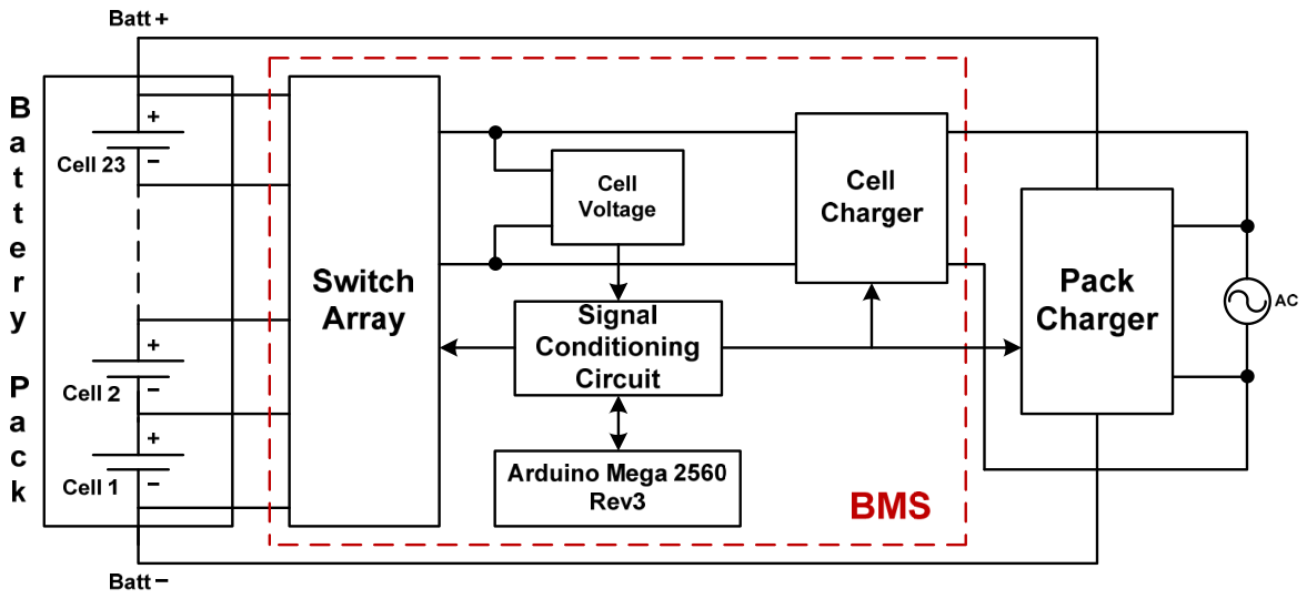
The proposed active cell balancing system based on cell chargers is presented in Figure 2. The proposed system consists of three main parts, namely a cell selecting switch (switch array), a cell charger, and a control section consisting of a microcontroller and its signal conditioning circuit. The first part is a switch array that connects battery cells for reading battery cell voltage and transferring energy during the balancing process. The second part is a cell charger for transferring energy from the electrical grid to low-voltage battery cells. The third part is a control circuit that regulates the switch array to read cell voltage and process the signal to control the operation of the cell charger or pack charger.
From Figure 2, a microcontroller (Arduino Mega 2560 Rev3) monitors the 23 battery cells’ voltage to ensure that the battery cells are protected from overvoltage and undervoltage conditions. The battery cell voltage is monitored through bidirectional switches (BDS) connected to the cells, where the operation of these switches is controlled by the microcontroller. The microcontroller processes the voltage data from the cells to decide whether to charge or balance them.

2.2. The Proposed Low-Cost Bidirectional Switch Circuit Design

In previous studies on low-cost cell balancing systems, the switches used in the switch array were relays [28] or bidirectional switches that used either N-channel or P-channel MOSFETs [29,30]. Table 1 shows a detailed comparison of previous low-cost battery cell balancing studies in terms of the number of components in the switch array and the energy sources used with the proposed battery cell balancing system.
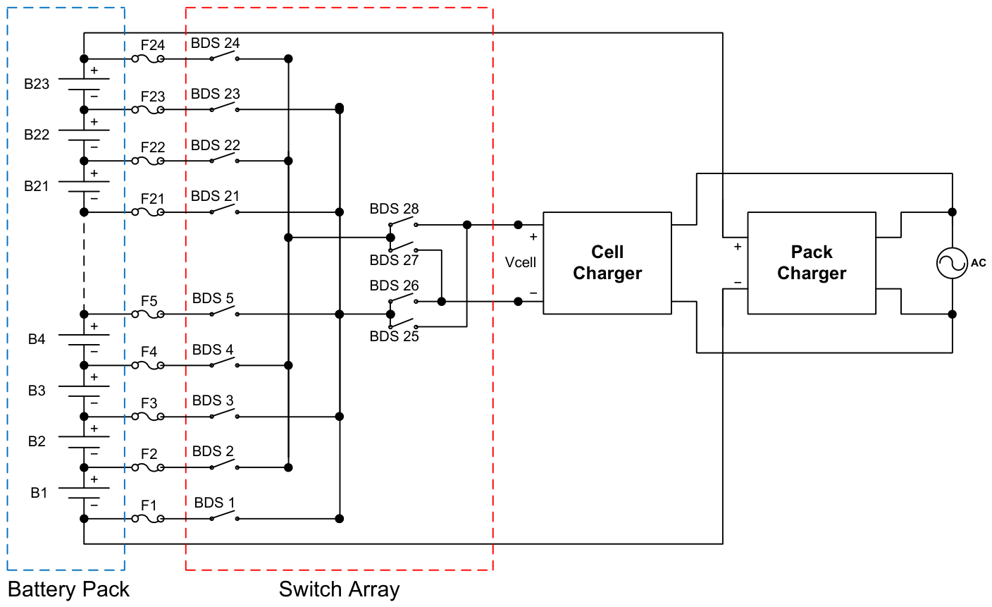
In this study, the switch configuration connected to each battery cell is displayed in Figure 3. In Figure 3, fuses are added to each battery cell connection to prevent short-circuiting in the event of switch failure. Reading the voltage of battery cells in a battery pack requires n + 5 switches, where n is the number of battery cells. Unlike conventional switch array-based active cell balancing, the number of switches used can be reduced by half. To read each battery cell’s voltage, 28 switches are required for 23 battery cells. The switches to be used are bidirectional switches (BDSs) using two N-channel MOSFETs with a common source configuration.
In Figure 3, BDS 25, BDS 26, BDS 27, and BDS 28 function as voltage polarity reversal devices for the battery cells whose voltage is to be read or balanced. BDS 26 and BDS 28 will be active simultaneously to connect to odd battery cells, namely B1, B3, B5, and so on up to B23. Conversely, BDS 25 and BDS 27 will be active simultaneously to connect to even battery cells, namely B2, B4, B6, and so on up to B22. There are four BDSs that must be active to read one of the battery cells. To read the voltage of battery cell 1, BDS 1, BDS 2, BDS 26, and BDS 28 are active. Next, to read the voltage of battery cell 2, BDS 2, BDS 3, BDS 25, and BDS 27 must be active. Similarly, to read the voltage of a specific battery cell, there are four BDSs that must be active with a specific configuration. This BDS configuration also aims to determine the specific cell that will be balanced by the cell charger. A BDS functions as a semiconductor switch with no moving parts, offering almost unlimited switch life, no contact vibration, and significantly higher switching speeds compared to relays. Modern MOSFETs in BDS can have very low on-resistance (RDS(on)), so power losses calculated using the I2xRDS(on) formula are minimal. The use of BDS is based on durability considerations compared to mechanical relays that still use mechanical contacts in their operation.
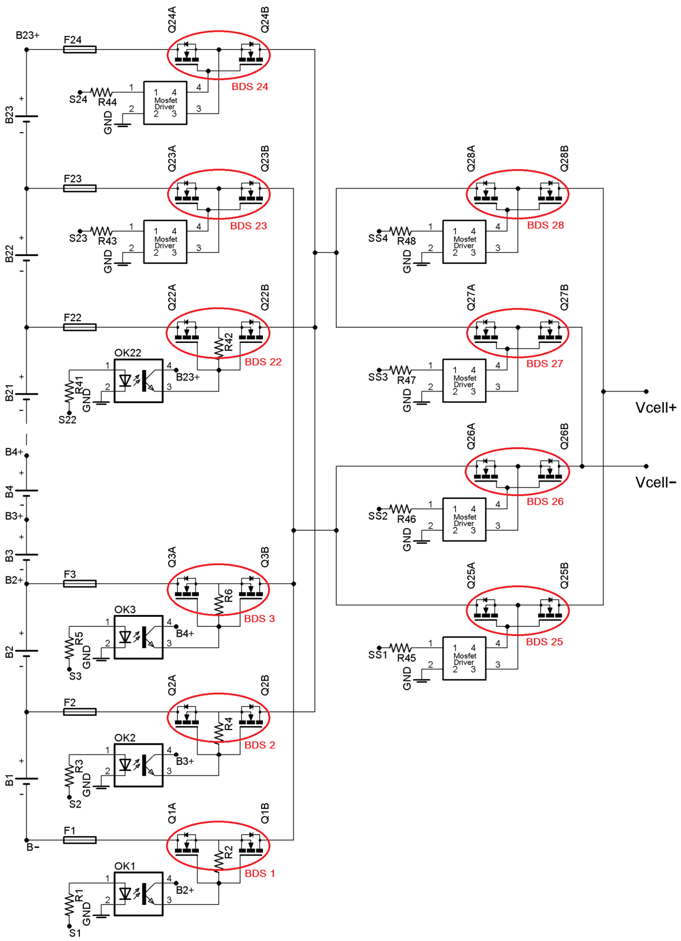
Unlike previous studies that used N-channel MOSFETs and P-channel MOSFETs on the top two switches of the battery pack, in this study, all MOSFETs used for BDSs are N-channel MOSFETs. BDSs with two N-channel MOSFETs in a common source configuration are used to monitor each battery cell’s voltage in the battery pack. The BDSs are activated via an optocoupler or MOSFET driver. The power required to activate the optocoupler or MOSFET driver is obtained from the battery cells, so no external power source is needed to activate the BDSs in the switch array. The BDSs are activated with a specific configuration as cell selection switches to prevent short circuits between cells. The BDS will be activated via an optocoupler except for the top two switches (BDS 23 and BDS 24) and four switches for voltage polarity (BDS 25, BDS 26, BDS 27, and BDS 28), which use a MOSFET driver to activate them. The use of N-channel MOSFETs and MOSFET drivers is still cheaper than using P-channel MOSFETs. The use of N-channel MOSFETs compared to P-channel MOSFETs will also reduce conduction losses, where the internal resistance (RDS(on)) of N-channel MOSFETs is smaller than that of P-channel MOSFETs. The details of the BDS circuit, along with the optocoupler and MOSFET driver, are shown in Figure 4.

2.3. Cell Charger

A cell charger is used to balance battery cells in the battery pack by charging cells that have lower voltages. The cell chargers used in this balancing process utilize components that are readily available on the market. This cell charger consists of an AC/DC isolated power module that converts AC voltage to DC voltage and a DC/DC converter that changes the AC/DC-isolated power module’s output voltage to the appropriate DC voltage for battery cell charging. In this experiment, 220 VAC was converted to 12 VDC using an isolated AC-DC power module from Shenzhen Hi-Link Electronic Co., Ltd. (Shenzhen, China) The 12 VDC voltage was then stepped down to the cell balancing voltage using a DC-DC converter module based on the XL4016 from Shanghai Xinlong Semiconductor Technology Co., Ltd. (Shanghai, China) with a maximum current capability of 8 A. This DC-DC converter module functions as a constant current-constant voltage (CC-CV) charger with an output voltage set to 4.5 VDC and a maximum current set to 3 A.

3. Equalization Control Strategy

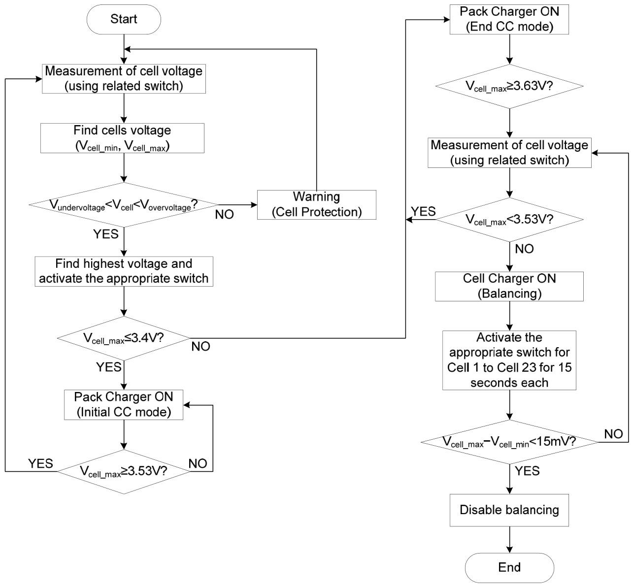
The proposed cell balancing algorithm is illustrated in Figure 5. Initially, the microcontroller would use bidirectional switches connected to each cell to periodically check its voltage. The microcontroller will provide a warning if the cell voltage is beyond limits (Vcell < Vmin and Vcell > Vmax). This condition also applies in the event of a switch failure or an open circuit, where the voltage of the battery cell connected to that switch is not detected (0 V).
The microcontroller will identify the highest cell voltage and turn on the corresponding bidirectional switches if all cell voltages are within limits (Vmin < Vcell < Vmax). The microcontroller will turn on the pack charger to begin the initial charging procedure if the highest cell voltage is lower than 3.4 V. This procedure will continue until the highest cell voltage is higher than 3.53 V. If the highest cell voltage surpasses 3.53 V, the microcontroller will re-read each battery cell’s voltage to determine the new highest cell voltage. The battery cell with the highest voltage will continue to be monitored until the battery pack charging process is complete. The battery pack charging process stops, and the cell balancing process begins if the highest cell voltage has reached the maximum permitted voltage limit of 3.63 V.
Cell balancing is performed if there are battery cells with a voltage below 3.53 V and begins by balancing cell 1, cell 2, and then continues until it reaches cell 23 for 15 s each. This balancing process is carried out until the maximum and minimum voltage differences between the cells are below 15 mV. The cell charger used in this cell balancing process draws power from the electrical grid.

4. Experimental Results

The LiFePO4 23S1P 100 Ah battery was used to test the proposed cell balancing design. The nominal voltage of 73.6 V produced by this battery pack is frequently utilized for electric motorcycles. A pack charger with an 83.9 V and 7 A voltage and current is utilized to charge the battery pack. The 23 battery cells’ voltage is monitored by the Analog Devices DC1894B module.
In this test, the discharge process of battery packs from a balanced battery condition was carried out for 30 min and 60 min with a discharge current of 30 A to see its effect on cell imbalance. After that, a 7 A charging current was applied to the battery pack until the battery cell voltage reached its maximum voltage. After the battery pack charging process was complete, the balancing process was carried out by charging the battery cells that still had a lower voltage compared to the highest battery cell voltage. This balancing process used a cell charger that drew energy from the grid with a balancing current of 3 A.
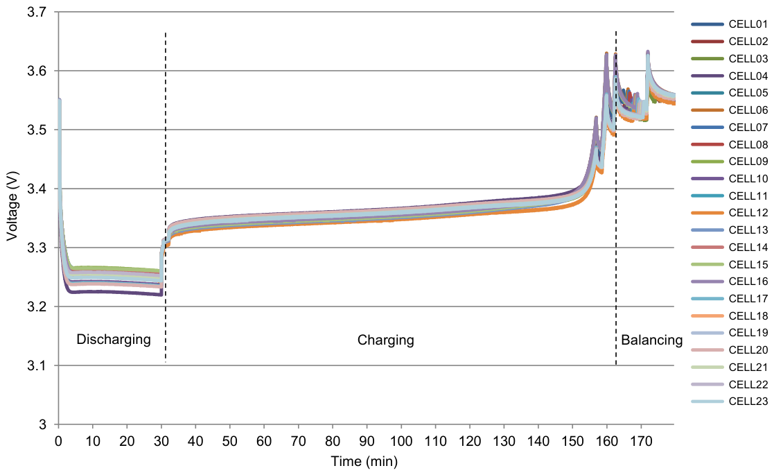
Figure 6 displays the results of testing the battery pack with a 30 min discharge followed by a charging and balancing process. The initial voltage before discharge, the final discharge voltage, the final charging voltage, and the final voltage after the balancing process for every cell monitored by the DC1894B module are presented in Table 2.
As shown in Figure 6, following a 30 min 30 A discharge process, a 7 A charge was applied for approximately 132 min until the battery cell with the highest voltage reached the maximum allowable voltage limit of 3.63 V. Once the maximum voltage limit was reached, a balancing process was performed for 17 min until the difference between the highest and lowest voltages was below 15 mV.
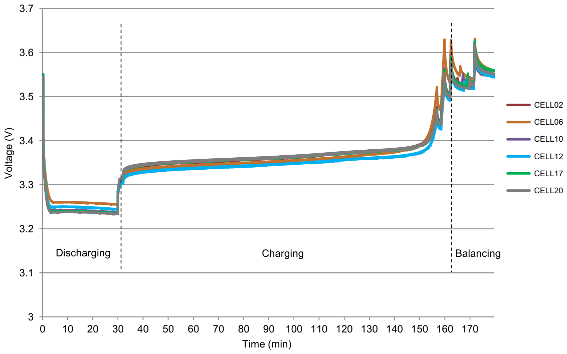
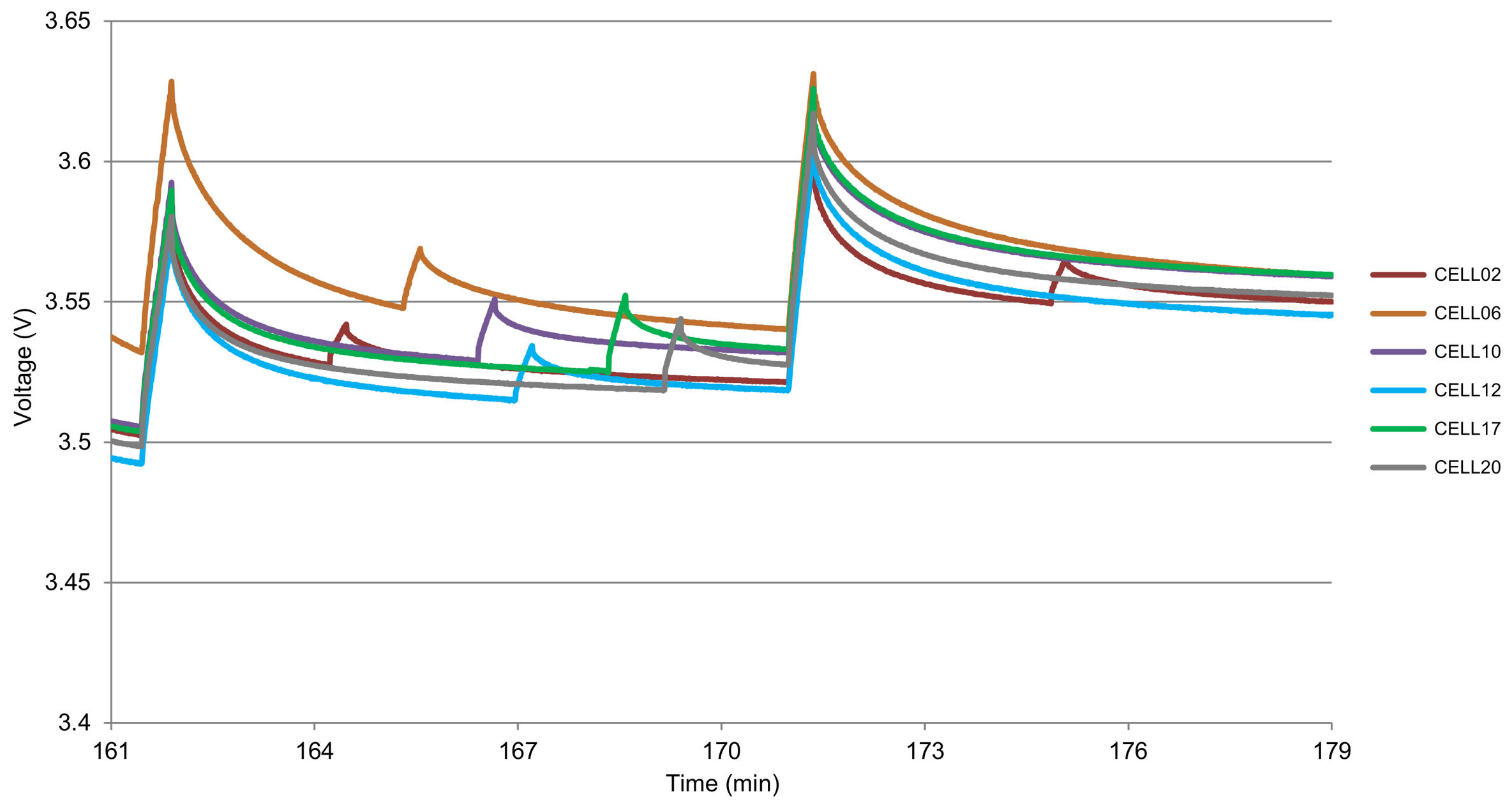
Table 2 shows that at the beginning of the discharge process, there was a 13.1 mV cell voltage difference between the highest and lowest voltages, where cell 12 had the lowest voltage and cell 10 had the highest voltage. The voltage difference between the highest and lowest cells after the discharge process was 50.9 mV, where the lowest voltage and highest voltage change to cell 2 and cell 20, respectively. After the battery pack was charged, the difference between the greatest and lowest cell voltages was 53.7 mV at the end of the charging operation, with the lowest voltage and highest voltage changing to cell 12 and cell 6, respectively. The difference between the highest and lowest cell voltages after the balancing procedure was 14.1 mV. The highest and lowest voltages during each process, as well as the voltage during the balancing process, are shown in further detail in Figure 7 and Figure 8.
From Figure 8, the cell balancing process starts from minute 162 to minute 179. During the balancing process, the highest cell voltage dropped below the balancing process voltage limit of 3.53 V, so the battery pack was recharged as displayed at minute 171. After the cell voltage had returned to the balancing process voltage limit, the balancing process was performed again until the cell difference met the specified limit of less than 15 mV. According to the test results, it took 17 min to balance the cells.
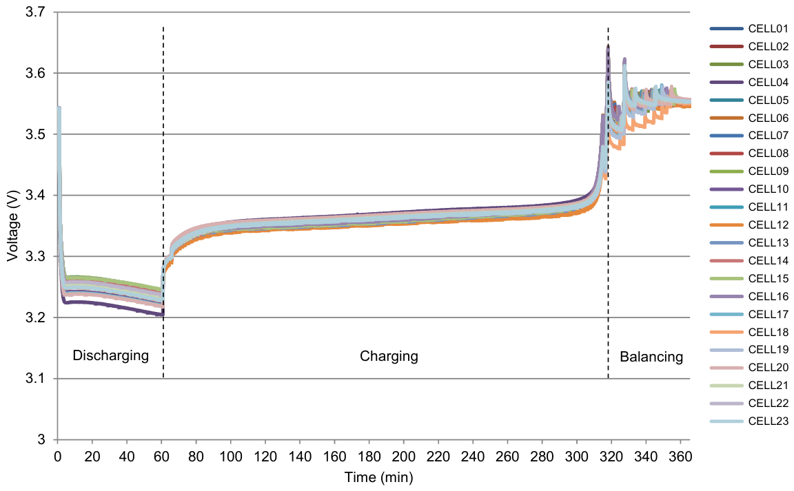
The results of testing the battery pack with a 60 min discharge process are shown in Figure 9, while the initial voltage before discharge, final discharge voltage, final charge voltage, and final voltage after the balancing process for each cell are presented in Table 3.
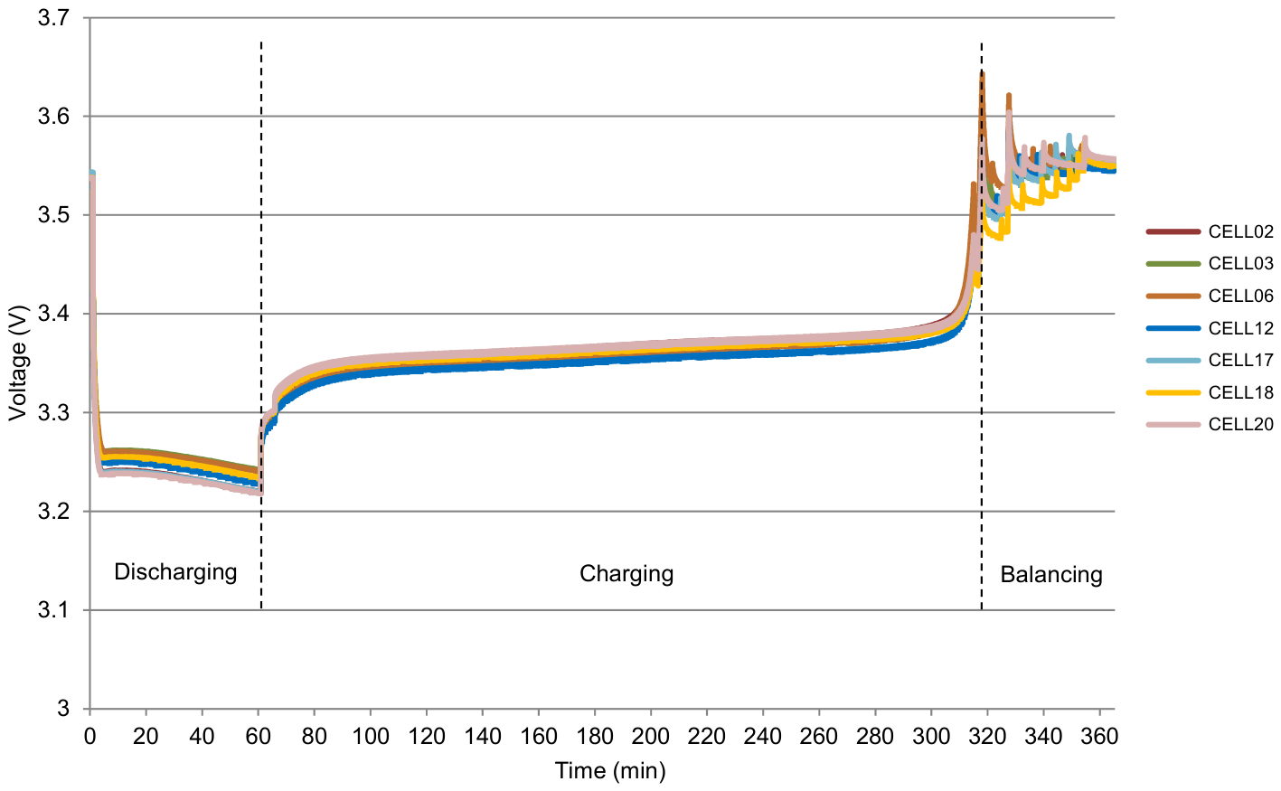
As illustrated in Figure 9, a 7 A charge was performed for roughly 258 min after a 60 min 30 A discharge procedure until the battery cell with the greatest voltage hit the maximum permitted voltage limit of 3.63 V. After the maximum voltage limit was achieved, a 40 min balancing procedure was carried out until the difference between the highest and lowest voltages was below 15 mV.
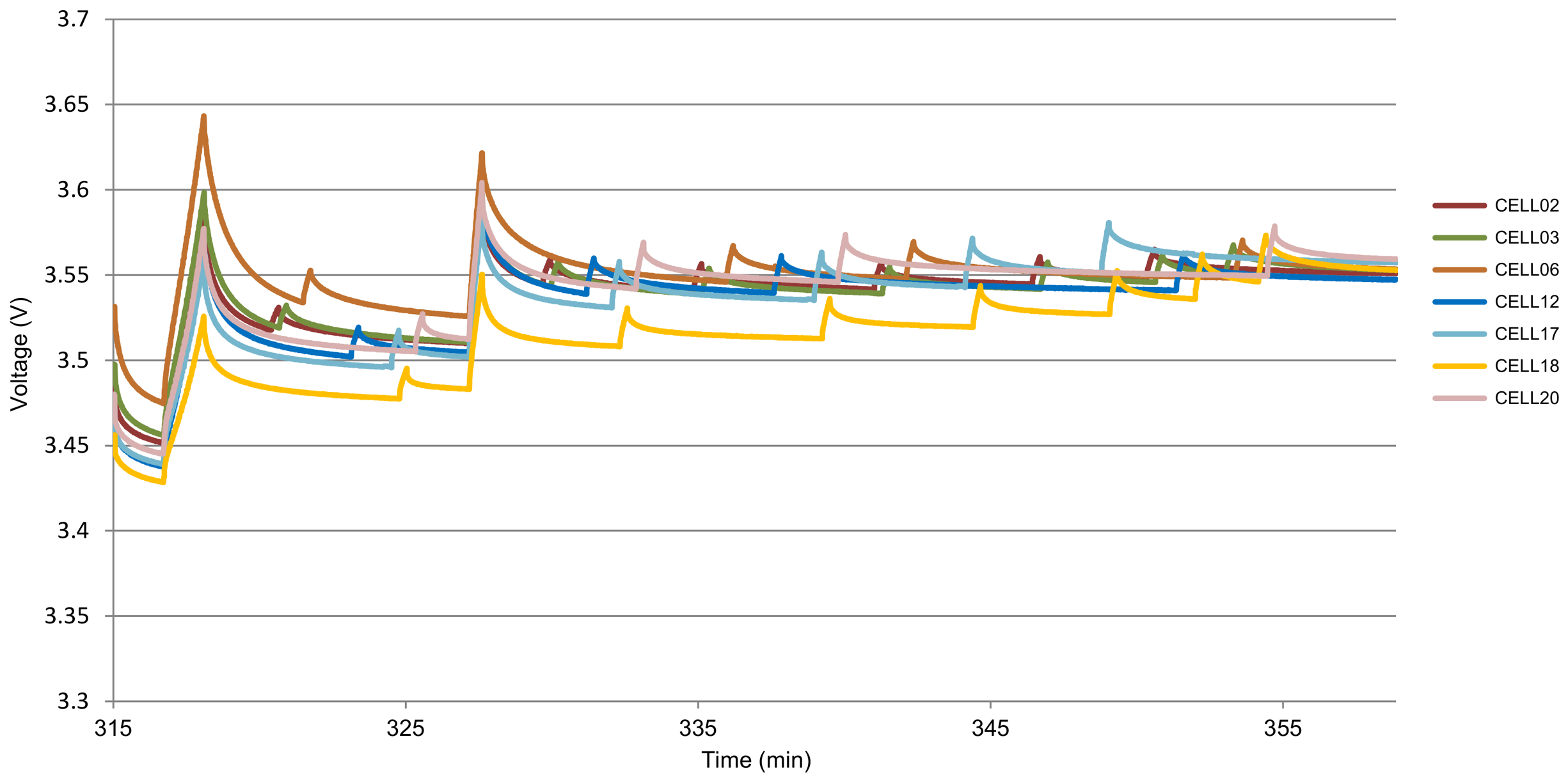
At the beginning of the discharge process, as shown in Table 3, there was a cell voltage difference of 15.6 mV between the highest and lowest voltages, with the lowest voltage and highest voltage being cell 3 and cell 17, respectively. The voltage difference between the highest and lowest cells after the discharge process was 49.9 mV, with the lowest voltage and highest voltage changing to cell 2 and cell 20, respectively. After the battery pack was recharged, the difference between the highest and lowest cell voltages increased dramatically to 116.7 mV, or twice that of the previous test, with the lowest voltage and highest voltage changing to cell 18 and cell 6, respectively. After the balancing process, the difference between the highest and lowest cell voltages was 11.8 mV with a balancing time of 40 min. The highest and lowest voltages during each process, as well as the voltage during the balancing process, are shown in further detail in Figure 10 and Figure 11.
From Figure 11, the cell balancing process starts from minute 318 to minute 358. During the balancing process, the highest cell voltage dropped below the balancing process voltage limit of 3.53 V, so the battery pack was recharged as displayed at minute 327. After the cell voltage had returned to the balancing process limit, the balancing process was performed again until the cell difference met the specified limit of less than 15 mV, with cell balancing taking 40 min.
In contrast to earlier research, which took 50 min to balance 12 batteries with a 74 Ah capacity or 12 batteries with a lesser capacity, this test took less time to balance 23 battery cells. Table 4 shows a comparison of the test results with previous studies.

5. Conclusions

The proposed low-cost battery balancing system with a switch array concept consisting of bidirectional switches that use only N-channel MOSFETs can be used to balance the voltage of 23 LiFePO4 100 Ah battery cells connected in series. There are 28 bidirectional switches (n + 5) utilized, which is almost half of the conventional switch configuration. As a cell balancer, a cell charger is used to charge battery cells that have low voltage. With a maximum balancing current of 3 A, this cell charger maximizes the energy already in the battery pack by using energy from the grid. According to the test data, it takes 40 min to balance the 23 cells, and the voltage difference between the highest and lowest cells drops from 116.7 mV to 11.8 mV.

Author Contributions

Conceptualization, A.A.; methodology, A.A. and F.Y.; writing—original draft preparation, A.A.; writing—review and editing, F.Y., F.H. and A.M.; supervision, F.Y., F.H. and A.M. All authors have read and agreed to the published version of the manuscript.

Funding

This research received no external funding.

Institutional Review Board Statement

Not applicable.

Informed Consent Statement

Not applicable.

Data Availability Statement

Dataset available on request from the authors.

Acknowledgments

The authors gratefully acknowledge the financial support for the article processing charge (APC) provided by the Unit of Research, Innovation, and Community Engagement, Faculty of Engineering, Universitas Indonesia, under the contract no NKB-1382/UN2.F4.D/PPM.00.04/2026.

Conflicts of Interest

The authors declare no conflicts of interest.

References

  1. König, A.; Nicoletti, L.; Schröder, D.; Wolff, S.; Waclaw, A.; Lienkamp, M. An Overview of Parameter and Cost for Battery Electric Vehicles. World Electr. Veh. J. 2021, 12, 21. [Google Scholar] [CrossRef]
  2. Zhang, J.; Long, T.; Sun, X.; He, L.; Yang, J.; Wang, J.; Wang, Z.; Huang, Y.; Zhang, L.; Zhang, Y. Mechanism Investigation on Microstructure Degradation and Thermal Runaway Propagation of Batteries Undergoing High-Rate Cycling Process. J. Energy Chem. 2026, 113, 1013–1029. [Google Scholar] [CrossRef]
  3. Buidin, T.I.C.; Cristea, M.; Cristea, C. Prediction of Retired EV Batteries’ Usable Capacity for Repurposing in Second-Life Applications. Technologies 2026, 14, 124. [Google Scholar] [CrossRef]
  4. He, C.; Xiao, L.; Zhang, J.; Wang, Z.; Wang, J.; Wang, L.; Zhang, L.; Wang, W.; Huang, Y.; Ouyang, D.; et al. Mechanistic Insights and Risk Evaluation of Thermal Runaway in Lithium-Ion Batteries under Coupled Temperature-Rate Conditions. Chem. Eng. J. 2026, 532, 174210. [Google Scholar] [CrossRef]
  5. Ashraf, A.; Ali, B.; Alsunjury, M.S.A.; Goren, H.; Kilicoglu, H.; Hardan, F.; Tricoli, P. Review of Cell-Balancing Schemes for Electric Vehicle Battery Management Systems. Energies 2024, 17, 1271. [Google Scholar] [CrossRef]
  6. Turksoy, A.; Teke, A.; Alkaya, A. A Comprehensive Overview of the Dc-Dc Converter-Based Battery Charge Balancing Methods in Electric Vehicles. Renew. Sustain. Energy Rev. 2020, 133, 110274. [Google Scholar] [CrossRef]
  7. Izadi, Y.; Beiranvand, R. A Comprehensive Review of Battery and Supercapacitor Cells Voltage-Equalizer Circuits. IEEE Trans. Power Electron. 2023, 38, 15671–15692. [Google Scholar] [CrossRef]
  8. Kumar Das, U.; Shrivastava, P.; Soon, K.; Yamani, M.; Bin, I.; Mekhilef, S.; Jamei, E.; Seyedmahmoudian, M.; Stojcevski, A. Advancement of Lithium-Ion Battery Cells Voltage Equalization Techniques: A Review. Renew. Sustain. Energy Rev. 2020, 134, 110227. [Google Scholar] [CrossRef]
  9. Ghaeminezhad, N.; Ouyang, Q.; Hu, X.; Member, S.; Xu, G.; Wang, Z. Active Cell Equalization Topologies Analysis for Battery Packs: A Systematic Review. IEEE Trans. Power Electron. 2021, 36, 9119–9135. [Google Scholar] [CrossRef]
  10. Yuan, L.; Ji, T.; Zhang, L. Active Methods for the Equalization of a Serially Connected Lithium-Ion Battery Pack: A Review. Batteries 2024, 10, 239. [Google Scholar] [CrossRef]
  11. Gabbar, H.A.; Othman, A.M.; Abdussami, M.R. Review of Battery Management Systems (BMS) Development and Industrial Standards. Technologies 2021, 9, 28. [Google Scholar] [CrossRef]
  12. Habib, A.K.M.A.; Hasan, M.K.; Issa, G.F.; Singh, D.; Islam, S.; Ghazal, T.M. Lithium-Ion Battery Management System for Electric Vehicles: Constraints, Challenges, and Recommendations. Batteries 2023, 9, 152. [Google Scholar] [CrossRef]
  13. Miranda, J.P.D.; Barros, L.A.M.; Pinto, J.G. A Review on Power Electronic Converters for Modular BMS with Active Balancing. Energies 2023, 16, 3255. [Google Scholar] [CrossRef]
  14. Uzair, M.; Abbas, G.; Hosain, S. Characteristics of Battery Management Systems of Electric Vehicles with Consideration of the Active and Passive Cell Balancing Process. World Electr. Veh. J. 2021, 12, 120. [Google Scholar] [CrossRef]
  15. Amin; Ismail, K.; Nugroho, A.; Kaleg, S. Passive Balancing Battery Management System Using MOSFET Internal Resistance as Balancing Resistor. In Proceedings of the 2017 International Conference on Sustainable Energy Engineering and Application (ICSEEA), Jakarta, Indonesia, 23–24 October 2017; pp. 151–155. [Google Scholar]
  16. Manas, M.; Yadav, R.; Dubey, R.K. Designing a Battery Management System for Electric Vehicles: A Congregated Approach. J. Energy Storage 2023, 74, 109439. [Google Scholar] [CrossRef]
  17. Ashok, B.; Kannan, C.; Mason, B.; Ashok, S.D.; Indragandhi, V. Towards Safer and Smarter Design for Lithium-Ion-Battery-Powered Electric Vehicles: A Comprehensive Review on Control Strategy Architecture of Battery Management System. Energies 2022, 15, 4227. [Google Scholar] [CrossRef]
  18. Liu, L.; Xu, B.; Yan, Z.; Zhou, W.; Li, Y.; Mai, R.; He, Z. A Low-Cost Multiwinding Transformer Balancing Topology for Retired Series-Connected Battery String. IEEE Trans. Power Electron. 2021, 36, 4931–4936. [Google Scholar] [CrossRef]
  19. Park, Y.H.; Kim, R.Y.; Choi, Y.J. An Active Cascaded Battery Voltage Balancing Circuit Based on Multi-Winding Transformer with Small Magnetizing Inductance. Energies 2021, 14, 1302. [Google Scholar] [CrossRef]
  20. Zheng, X.; Liu, X.; He, Y.; Zeng, G. Active Vehicle Battery Equalization Scheme in the Condition of Constant-Voltage/Current Charging and Discharging. IEEE Trans. Veh. Technol. 2017, 66, 3714–3723. [Google Scholar] [CrossRef]
  21. Singirikonda, S.; Obulesu, Y.P. Active Cell Voltage Balancing of Electric Vehicle Batteries by Using an Optimized Switched Capacitor Strategy. J. Energy Storage 2021, 38, 102521. [Google Scholar] [CrossRef]
  22. Zhou, G.; Zhang, X.; Gao, K.; Tian, Q.; Xu, S. Two-Mode Active Balancing Circuit Based on Switched-Capacitor and Three-Resonant-State LC Units for Series-Connected Cell Strings. IEEE Trans. Ind. Electron. 2022, 69, 4845–4858. [Google Scholar] [CrossRef]
  23. Liu, F.; Zou, R.; Liu, Y. An Any-Cell-to-Any-Cell Battery Equalizer Based on Half-Bridge LC Converter. IEEE Trans. Power Electron. 2023, 38, 4218–4223. [Google Scholar] [CrossRef]
  24. Zong, Y.; Li, K.; Wang, Q.; Meng, J. Multi-Mode Lithium-Ion Battery Balancing Circuit Based on Forward Converter with Resonant Reset. Appl. Sci. 2023, 13, 10430. [Google Scholar] [CrossRef]
  25. Lee, S.; Noh, G.; Ha, J.I. Reconfigurable Power Circuits to Series or Parallel for Energy-Balanced Multicell Battery Pack. IEEE Trans. Ind. Electron. 2023, 70, 3641–3651. [Google Scholar] [CrossRef]
  26. Huang, H.; Ghias, A.M.Y.M.; Acuna, P.; Dong, Z.; Zhao, J.; Reza, M.S. A Fast Battery Balance Method for a Modular-Reconfigurable Battery Energy Storage System. Appl. Energy 2024, 356, 122470. [Google Scholar] [CrossRef]
  27. Khan, N.; Ai Ooi, C.; Alturki, A.; Amir, M. A Critical Review of Battery Cell Balancing Techniques, Optimal Design, Converter Topologies, and Performance Evaluation for Optimizing Storage System in Electric Vehicles. Energy Rep. 2024, 11, 4999–5032. [Google Scholar] [CrossRef]
  28. Pham, V.; Duong, V.; Choi, W. A Low Cost and Fast Cell-to-Cell Balancing Circuit for Lithium-Ion Battery Strings. Electronics 2020, 9, 248. [Google Scholar] [CrossRef]
  29. Sun, C.; Chou, C.; Lin, Y.; Huang, Y. A Cost-Effective Passive/Active Hybrid Equalizer Circuit Design. Energies 2022, 15, 2000. [Google Scholar] [CrossRef]
  30. Dinh, M.; Le, T.; Park, M. A Low-Cost and High-Efficiency Active Cell-Balancing Circuit for the Reuse of EV Batteries. Batteries 2024, 10, 61. [Google Scholar] [CrossRef]
  31. Duan, C.; Wang, C.; Li, Z.; Chen, J.; Wang, S.; Snyder, A.; Jiang, C. A Solar Power-Assisted Battery Balancing System for Electric Vehicles. IEEE Trans. Transp. Electrif. 2018, 4, 432–443. [Google Scholar] [CrossRef]
  32. Zhang, H.; Wang, Y.; Qi, H.; Zhang, J. Active Battery Equalization Method Based on Redundant Battery for Electric Vehicles. IEEE Trans. Veh. Technol. 2019, 68, 7531–7543. [Google Scholar] [CrossRef]
  33. Jiang, B.; Liu, Y.; Huang, X.; Prakash, R.R.R. A New Battery Active Balancing Method with Supercapacitor Considering Regeneration Process. In Proceedings of the IECON 2020 The 46th Annual Conference of the IEEE Industrial Electronics Society, Singapore, 18–21 October 2020; pp. 2364–2369. [Google Scholar] [CrossRef]
  34. Wang, Y.; Liu, P.; Jin, X.; Zhang, K.; Cheng, Y.; Yin, W. Design and Experiment of a Novel Stepwise Preheating System for Battery Packs Coupled with Non-Dissipative Balancing Function Based on Supercapacitors. J. Energy Storage 2023, 66, 107444. [Google Scholar] [CrossRef]
  35. Riczu, C.; Bauman, J. Implementation and System-Level Modeling of a Hardware Efficient Cell Balancing Circuit for Electric Vehicle Range Extension. IEEE Trans. Ind. Appl. 2021, 57, 2883–2895. [Google Scholar] [CrossRef]
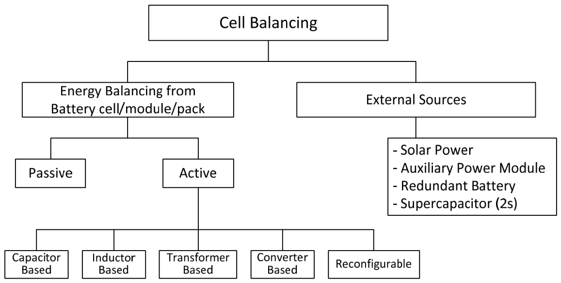
Figure 1. The classification of cell balancing based on the energy source used for balancing.
Technologies 14 00298 g001
Figure 2. The proposed cell balancing system.
Technologies 14 00298 g002
Figure 3. BDS configuration on the switch array.
Technologies 14 00298 g003
Figure 4. The proposed BDS circuit.
Technologies 14 00298 g004
Figure 5. The proposed cell balancing control algorithm.
Technologies 14 00298 g005
Figure 6. The voltage of each battery cell with battery discharge for 30 min, followed by the charging and balancing process.
Technologies 14 00298 g006
Figure 7. The highest and lowest voltages during the 30-min discharge, charge, and equalization processes.
Technologies 14 00298 g007
Figure 8. The voltage of each battery cell during the cell balancing process after 30 min of discharge.
Technologies 14 00298 g008
Figure 9. The voltage of each battery cell with battery discharge for 60 min, followed by the charging and balancing process.
Technologies 14 00298 g009
Figure 10. The highest and lowest voltages during the 60-min discharge, charge, and equalization processes.
Technologies 14 00298 g010
Figure 11. The voltage of each battery cell during the cell balancing process after 60 min of discharge.
Technologies 14 00298 g011
Table 1. Comparison of previous low-cost cell balancing methods with the proposed method.
ParametersReferencesProposed Method
Cell-to-Cell [28]Passive/Active [29]Cell-to-Cell [30]
No. of cells12221223
No. of switches244414 + 2 three-pole switches28
Switch typeRelayBidirectional SwitchBidirectional SwitchBidirectional Switch
MOSFET type041 Dual N-MOSFETs and 3 Dual P-MOSFETs10 Dual N-MOSFETs and
4 Dual P-MOSFETs
28 Dual N-MOSFETs
MOSFET driver0 (4 Transistors array)85 Transistors14 Optocouplers22 Optocouplers +
6 MOSFET Drivers
Switch lossesVery LowMediumMediumLow
Cost (switch array)Very LowMediumMediumLow
Balancing sourceBattery packAuxiliary batteryBattery packAC power/ Grid
Table 2. The voltage of each cell for 30 min of discharge.
CellVoltage (V)
InitialEnd DischargingEnd ChargingEnd Balancing
Cell 13.54343.24923.60843.5566
Cell 23.54353.23563.58213.5501
Cell 33.54153.25663.57993.5476
Cell 43.54493.28383.59553.5483
Cell 53.54063.28253.61883.5545
Cell 63.54443.25513.62853.5594
Cell 73.54393.28283.62613.5583
Cell 83.54293.2833.62263.5563
Cell 93.54763.28613.57983.5548
Cell 103.55093.28643.59263.5592
Cell 113.54733.28543.5853.5546
Cell 123.53783.27423.57483.5455
Cell 133.54263.25913.62323.5571
Cell 143.54333.25863.62333.5573
Cell 153.5423.26033.6233.5561
Cell 163.54393.28393.62673.5588
Cell 173.553.28643.58973.5596
Cell 183.54443.2863.57793.5531
Cell 193.54863.28573.58343.5581
Cell 203.54433.28653.58053.5523
Cell 213.54773.2843.58323.5567
Cell 223.54983.28463.58663.5593
Cell 233.54833.28323.58653.5582
Table 3. The voltage of each cell for 60 min of discharge.
CellVoltage (V)
InitialEnd DischargingEnd ChargingEnd Balancing
Cell 13.53613.23373.60733.5549
Cell 23.5313.21983.57183.5508
Cell 33.52793.24183.58953.5529
Cell 43.53033.26693.57683.554
Cell 53.53473.26623.6233.55
Cell 63.5383.26693.63233.5534
Cell 73.53763.26683.63093.5506
Cell 83.53673.26663.62433.5562
Cell 93.54013.26913.56773.5553
Cell 103.54293.26933.57463.5522
Cell 113.53933.26843.56923.5558
Cell 123.52913.25663.56293.5474
Cell 133.53743.24483.63083.5537
Cell 143.5373.24343.62873.5513
Cell 153.53593.24563.62993.5591
Cell 163.53783.26733.62943.5546
Cell 173.54353.26933.54523.5572
Cell 183.5383.26873.51563.5527
Cell 193.54223.26863.54233.5552
Cell 203.53763.26973.56223.5592
Cell 213.54113.26723.57043.5539
Cell 223.54283.26793.57473.5552
Cell 233.54153.26623.57293.5548
Table 4. A comparison of previous experimental results with the proposed method.
ParametersReferencesProposed Method
[28][30]
Number of Cells121223
Battery CapacityNA (low)74 Ah100 Ah
Balancing CurrentNA4 A3 A
Initial Voltage Difference180 mV70 mV53.7 mV116.7 mV
Final Voltage Difference12 mV4 mV14.1 mV11.8 mV
Balancing Time54 min134 min17 min40 min
Disclaimer/Publisher’s Note: The statements, opinions and data contained in all publications are solely those of the individual author(s) and contributor(s) and not of MDPI and/or the editor(s). MDPI and/or the editor(s) disclaim responsibility for any injury to people or property resulting from any ideas, methods, instructions or products referred to in the content.