Review

Antenna Performance and Effects of Concealment Within Building Structures: A Comprehensive Review

by
Mirza Farrukh Baig
and
Ervina Efzan Mhd Noor
*
Centre for Manufacturing and Environmental Sustainability, Faculty of Engineering and Technology, Multimedia University, Bukit Beruang, Malacca 75450, Malaysia
*
Author to whom correspondence should be addressed.
Technologies 2026, 14(5), 259; https://doi.org/10.3390/technologies14050259
Submission received: 27 February 2026 / Revised: 21 April 2026 / Accepted: 23 April 2026 / Published: 25 April 2026
(This article belongs to the Section Information and Communication Technologies)

Abstract

The rapid expansion of wireless communication in urban environments requires antenna systems that balance high electromagnetic performance with stringent aesthetic and security constraints. This review examines recent advances in concealed antenna technologies integrated into building structures, with a focus on performance variation, material-induced attenuation, and emerging concealment strategies. Techniques such as transparent conductors on glass, structural embedding within walls, and camouflage-based designs are shown to significantly influence resonance behavior, radiation efficiency, and pattern characteristics compared to free-space operation. Despite these challenges, optimized solutions including transparent conductive oxide arrays, wideband embedded antenna geometries, and metasurface-enhanced window structures can partially recover performance while maintaining optical transparency above 70%. Material loading effects are found to induce resonant frequency shifts of approximately 10–44%, depending on dielectric properties and environmental conditions. Transparent antenna arrays achieve gains ranging from 0.34 to 13.2 dBi, while signal-transmissive wall systems demonstrate transmission improvements of up to 22 dB relative to untreated building materials. These technologies enable a wide range of applications, including 5G and beyond-5G cellular networks across sub-6 GHz and millimeter-wave bands, as well as Internet of Things systems and smart city infrastructure. However, key challenges remain, including the need for comprehensive characterization of building material electromagnetic properties, optimization of multilayer structural environments, and the development of standardized design and evaluation methodologies. This review provides a unified framework for understanding the tradeoffs associated with antenna concealment and identifies critical research directions for the development of building-integrated wireless systems in next-generation communication networks.

1. Introduction

The proliferation of wireless communication systems in urban environments has created an inherent tension between the technical requirements for ubiquitous radio frequency coverage and societal demands for aesthetic preservation, architectural integrity, and visual harmony in built spaces. Traditional antenna installations, typically characterized by visible masts, panels, and radomes, increasingly face regulatory restrictions, public opposition, and integration challenges in heritage districts, residential areas, and modern architectural designs [1,2,3]. This conflict has intensified with the deployment of fifth-generation (5G) cellular networks and the anticipated rollout of sixth-generation (6G) systems, which require denser base station deployments and higher frequency operation to achieve target data rates and latency specifications [4,5,6,7].
Beyond aesthetic considerations, antenna concealment addresses critical operational requirements including security and covert deployment scenarios where visible infrastructure may be undesirable or prohibited [8]. The integration of antennas into building structures offers additional benefits: reduced installation costs through leveraging existing architectural elements [9], protection from environmental degradation, and opportunities for dual-function designs that combine communication capabilities with structural or energy-harvesting functions [10]. Urban densification and the emergence of smart city paradigms further necessitate innovative approaches to antenna placement, as traditional tower-based infrastructure cannot scale to meet the connectivity demands of Internet of Things (IoT) sensor networks, autonomous vehicles, and pervasive computing applications [11,12].
The technical challenge lies in achieving effective concealment while maintaining acceptable electromagnetic performance. Antenna operation fundamentally depends on precise geometric dimensions, unobstructed radiation paths, and controlled impedance environments, all of which are compromised when antennas are embedded in dielectric materials, printed with lossy transparent conductors, or integrated into multi-layer building assemblies [13]. Understanding and mitigating these performance impacts constitutes a critical research frontier at the intersection of antenna engineering, materials science, and architectural design.
This review provides a comprehensive assessment of current knowledge on antenna performance when concealed within or integrated into building structures. It examines the electromagnetic impacts of concealment, including resonant frequency shifts, reductions in gain and efficiency, modifications to radiation patterns, and bandwidth variations. Particular attention is given to material specific influences of common construction materials such as concrete, glass, multilayer wall systems, and advanced composites, with emphasis on dielectric loading, loss tangent, and frequency dependent attenuation. The review further evaluates existing concealment technologies, including transparent conductive oxides, antenna on glass configurations, structural embedding methods, camouflage-based designs, and metasurface enhanced solutions. It also explores key application domains where concealed antennas provide essential functionality, such as 5G and 6G cellular networks, Internet of Things deployments, structural health monitoring, and indoor coverage enhancement.
In addition, practical design guidelines and optimization strategies are discussed to support engineers in balancing concealment requirements with performance targets. Current research gaps are identified, and future directions are proposed to advance concealed antenna technologies for next generation wireless systems. The scope of this review covers antennas operating from ultra-high-frequency bands around 860 MHz to millimeter wave frequencies up to Ka band, approximately 40 GHz. Both passive antenna elements and active systems with integrated electronics are considered, with primary focus placed on electromagnetic performance rather than circuit level implementation details.

Review Methodology

A systematic literature review was conducted to ensure comprehensive and unbiased coverage of concealed and building integrated antenna technologies. Major databases, including Scopus, Web of Science, and IEEE Xplore, were used to identify relevant studies. The search employed targeted keywords such as “concealed antennas,” “building integrated antennas,” “transparent antennas,” and “metasurface antennas,” combined with application terms including “5G,” “6G,” “millimeter wave,” and “IoT.” The search was limited to publications from 2010 to 2026 to capture recent developments.
Clear inclusion and exclusion criteria were applied to select relevant studies. Papers were included if they addressed antennas integrated within building materials and provided quantitative electromagnetic performance results, while studies lacking validation or focusing only on circuit level design were excluded. A multi stage screening process was followed, including duplicate removal, title and abstract screening, and full text evaluation. This resulted in 30 representative papers, which were analyzed to identify key trends, material effects, and design strategies, ensuring a transparent and rigorous review process.

2. Background and Theoretical Foundations

2.1. Electromagnetic Principles of Antenna Concealment

Antenna operation is governed by Maxwell’s equations, which describe the generation and propagation of electromagnetic fields in response to time-varying currents and charges [14]. The fundamental resonance condition for an antenna relates its physical dimensions to the operating wavelength, typically requiring radiating elements on the order of λ/4 to λ/2 for efficient operation, where λ is the free-space wavelength. When an antenna is placed in proximity to or embedded within dielectric materials, the effective wavelength is reduced according to λ e f f = λ 0 / ε r , where λ 0 is the free-space wavelength and ε r is the relative permittivity of the surrounding medium [15]. This wavelength compression necessitates either physical miniaturization of the antenna or acceptance of a downward shift in resonant frequency [16,17,18].
The radiation efficiency of an antenna quantifies the ratio of radiated power to input power, with losses arising from conductor resistance (ohmic losses), dielectric absorption in substrate and surrounding materials, and impedance mismatch [19]. Concealment strategies that employ lossy materials, such as transparent conductive oxides with sheet resistances orders of magnitude higher than copper, or embedding within concrete that has a non-zero loss tangent, directly reduce radiation efficiency [20]. The relationship between material conductivity σ and skin depth δ = 2 / ω μ σ further constrains the minimum conductor thickness required for effective current flow, creating fundamental tradeoffs between optical transparency (favoring thin, sparse conductors) and electromagnetic performance (favoring thick, continuous conductors) [21,22].
Radiation patterns describe the angular distribution of radiated power and are determined by the antenna geometry, ground plane configuration, and near-field environment [23]. Embedding antennas in building structures introduces asymmetric dielectric loading, which can distort radiation patterns, create unwanted nulls, and reduce front-to-back ratio [24]. Multi-layer wall assemblies with varying permittivity and thickness act as stratified media, supporting multiple reflections and transmission coefficients that depend on frequency, polarization, and incidence angle according to Fresnel equations and transmission line theory [25,26].

2.2. Material-Antenna Interactions

Building materials exhibit frequency-dependent electromagnetic properties characterized by complex permittivity ε r = ε j ε and complex permeability μ = μ j μ . For most non-magnetic building materials, μ μ 0 (free-space permeability), while the real part of permittivity ε′ (dielectric constant) and the loss tangent tan δ = ε / ε govern wave propagation and attenuation [27]. Concrete typically exhibits ε r in the range 4–8 depending on composition, moisture content, and curing state, with loss tangent values of 0.01–0.1 [28]. Glass substrates used in windows generally have ε r 4 7 with low loss tangent (<0.01) in the microwave regime, though low-emissivity coatings and metallic films can dramatically alter transmission characteristics [29,30,31].
When an antenna is embedded in a dielectric material, the effective permittivity experienced by the antenna depends on the spatial distribution of fields and the geometry of the embedding. For a patch antenna on a substrate, the effective permittivity can be approximated by ε e f f ε r + 1 / 2 + ε r 1 / 2 × [ 1 + 12 h W ] 1 / 2 , where h is substrate thickness and W is patch width. However, for fully embedded antennas or complex multi-layer structures, numerical electromagnetic simulation is typically required to accurately predict resonance and radiation characteristics [32].
Moisture content significantly affects the electromagnetic properties of porous materials like concrete, as water has a high dielectric constant ( ε r 80 at microwave frequencies) and moderate loss tangent [33]. Studies of antennas embedded in concrete for structural health monitoring applications have documented resonant frequency shifts exceeding 40% between freshly poured (high moisture) and fully cured (low moisture) states, along with corresponding changes in impedance matching and radiation efficiency [34]. This time-dependent behavior complicates the design of permanently embedded antenna systems and necessitates either robust wideband designs or adaptive tuning mechanisms.

2.3. Performance Metrics for Concealed Antennas

Evaluating concealed antenna performance requires consideration of multiple interdependent metrics:
Resonant Frequency and Bandwidth: The frequency at which the antenna achieves minimum reflection coefficient (maximum return loss), typically defined by |S11| < −10 dB. Bandwidth quantifies the frequency range over which acceptable impedance matching is maintained, often specified as fractional bandwidth (BW/f0) or absolute bandwidth in MHz or GHz.
Gain and Directivity: Gain (in dBi) measures the antenna’s ability to concentrate radiated power in a preferred direction relative to an isotropic radiator, accounting for all losses. Directivity excludes mismatch and conductor losses, representing only the pattern shaping effect. For concealed antennas, gain degradation relative to free-space operation is a primary performance indicator.
Radiation Efficiency: The ratio of radiated power to accepted power (excluding reflection losses), typically expressed as a percentage or in dB. Transparent conductor antennas often exhibit efficiencies below 10%, while optimized embedded designs can achieve 50–80% efficiency [35].
Radiation Pattern: The angular distribution of radiated power, characterized by beam width (half-power or 3 dB beam width), front-to-back ratio, side lobe levels, and cross-polarization discrimination. Concealment-induced pattern distortion can create coverage gaps or interference issues in practical deployments.
Transmission Coefficient: For signal-transmissive wall designs, the transmission coefficient |S21| quantifies the power transmitted through the structure, with improvements of 10–22 dB reported for optimized embedded antenna arrays compared to raw building materials [36].
Optical Transparency: For transparent antenna applications, optical transmittance in the visible spectrum (400–800 nm) is a critical non-electromagnetic metric, with values exceeding 70–90% required for window integration [37].

3. Electromagnetic Performance Impacts of Concealment

3.1. Resonant Frequency Shifts and Impedance Matching

Dielectric loading from building materials systematically shifts antenna resonant frequencies downward, with the magnitude of shift depending on the permittivity, geometry, and extent of material coverage. An electrically small complementary split ring resonator (CSRR) loaded antenna embedded in Ordinary Portland Cement pastes with varying iron(III) oxide inclusions was investigated, demonstrating that material loading induces systematic downward shifts in resonant frequency along with corresponding variations in impedance matching [38]. The antenna, optimized for 3.50 GHz operation in free space, exhibited altered resonance characteristics when embedded in cementitious composites, requiring re-optimization of geometric parameters to restore target frequency operation.
More pronounced frequency shifts occur in high-moisture environments. In studies of Radio Frequency (RF) energy-powered sensor nodes embedded in concrete for structural health monitoring, a 915 MHz antenna was observed to undergo a resonant frequency shift from 898 MHz to 510 MHz when placed in freshly poured concrete, corresponding to a 44% downward shift [39]. The S11 parameter decreased across the frequency band and the reflection profile flattened, suggesting broader bandwidth but significantly decreased efficiency due to absorption in the high-moisture concrete. As the concrete cured over 10 days, the resonant frequency gradually recovered toward the design value as moisture content decreased, demonstrating the time-dependent nature of material loading effects.
For antennas embedded in load-bearing walls with multi-layer thermal insulation, analytical models were developed to predict electromagnetic transmission, and wideband back to back spiral antenna systems were optimized for operation within wall assemblies [2]. The design process required iterative electromagnetic-thermal co-simulation to ensure that antenna geometries maintained acceptable impedance matching across the 2.6–8 GHz band while preserving the thermal insulation properties of the wall structure. The optimized signal-transmissive wall demonstrated a 22 dB improvement in electromagnetic transmission compared to the raw load-bearing wall, achieved through careful tuning of spiral dimensions and spacing to compensate for dielectric loading effects.
Impedance matching is further complicated by the frequency-dependent nature of material properties and the potential for multi-mode resonances in complex geometries. Transparent conductor antennas on glass substrates exhibit different matching characteristics than their copper counterparts due to the distributed resistance of the transparent film, which can broaden impedance bandwidth at the expense of radiation efficiency [40]. Design strategies to address resonance shifts include: (1) pre-compensation by designing the free-space antenna at a higher frequency to account for expected downward shift, (2) use of matching networks or tuning elements to restore impedance matching post-embedding, and (3) adoption of inherently wideband antenna topologies (e.g., spirals, log-periodic arrays) that maintain acceptable matching despite frequency shifts.

3.2. Gain and Efficiency Degradation

Concealment strategies impose fundamental tradeoffs between visual transparency or structural integration and electromagnetic performance, with gain and efficiency being the most severely impacted metrics. Comparative studies of transparent antenna arrays using gallium doped zinc oxide (GZO) and conventional copper conductors were conducted, revealing significant performance differences [6,41]. A single GZO antenna element achieved approximately 8% radiation efficiency and a gain of −10.87 dBi, compared to 2.18 dBi for an equivalent copper element, a degradation exceeding 13 dB. The poor performance stems from the high sheet resistance of GZO films (typically 10–50 Ω/square) compared to copper (<0.01 Ω/square), resulting in substantial ohmic losses that convert input power to heat rather than radiated electromagnetic energy.
Array configurations provide a pathway to partially recover gain losses. A 4 × 1 array of GZO elements was shown to increase the gain to 0.34 dBi, representing an approximate 11 dB improvement over a single element through coherent power combining [6]. However, the array gain remained approximately 10 dB below an equivalent copper array, indicating that arraying mitigates but does not eliminate the fundamental conductivity limitations of transparent materials. The study further investigated meshed conductor approaches, finding that increasing optical transparency from 70% to 95% through reduced mesh density decreased gain by 0.80 dB and 2.42 dB, respectively, with efficiency dropping from 60% to 56% [6]. These results quantify the direct tradeoff between transparency and performance, providing design guidance for applications with specific visibility requirements.
For camouflaged pico-cell base stations, a 2 × 2 transparent antenna array using indium tin oxide (ITO) on glass laminates was developed, achieving a realized gain of 13.2 dBi with 77% visual transparency [5]. The relatively high gain was enabled by the array configuration, optimized feed network design, and use of ITO with higher conductivity than GZO. The system demonstrated reflection coefficients better than −15 dB and port-to-port coupling less than −23 dB across the 5G sub-6 GHz band (3.3–3.8 GHz), with a 3 dB solid angle of 33° × 33° suitable for pico-cell coverage scenarios. This represents a successful balance between concealment and performance for practical deployment, though the gain remains lower than conventional metal antenna arrays of similar size.
Antennas embedded in concrete for structural health monitoring face even more severe efficiency challenges due to high dielectric losses in the surrounding material. An evolutionary-optimized antenna embedded in concrete achieved a gain of −8.4 dBi at 4.2% concrete water content after 157 days of drying [34]. The study found that increasing concrete conductivity (through higher moisture or conductive additives) rapidly decreases gain, while permittivity has less influence on efficiency. Path loss measurements revealed 82 dB attenuation at 3.5 cm depth in freshly poured concrete at 915 MHz, decreasing to 43 dB and 29 dB after 12 h and 10 days, respectively, as moisture content reduced. These extreme losses necessitate either very high transmit powers or close proximity between embedded antennas and external readers, limiting practical applications to short-range sensing scenarios.

3.3. Radiation Pattern Alterations

Concealment within building structures introduces asymmetric dielectric loading and near-field scattering objects that distort radiation patterns relative to free-space operation. The effects of complex wall structures on antenna radiation characteristics were investigated, showing that multi-layer assemblies with varying permittivity and thickness lead to pattern distortions, unwanted nulls, and changes in polarization characteristics [42]. The magnitude of pattern distortion depends on the electrical thickness of the wall (thickness in wavelengths), the permittivity contrast between layers, and the antenna’s position relative to the wall structure.
For transparent antenna arrays designed for pico-cell applications, maintaining controlled radiation patterns is critical for coverage planning and interference management. A 2 × 2 ITO array was demonstrated to achieve a 3 dB solid angle of 33° × 33°, providing relatively symmetric coverage suitable for street-level pico-cell deployment [5]. The back-to-back configuration with separate radiating and feeding layers enabled independent control of inward and outward radiation patterns, with isolation better than 25 dB between ports serving opposite directions [43]. This design approach addresses the challenge of providing simultaneous indoor and outdoor coverage from window-mounted antennas while minimizing interference between the two coverage zones [44].
Signal-transmissive walls with embedded antenna arrays exhibit frequency-dependent transmission patterns determined by the array geometry and element spacing. Optimized spiral antenna arrays embedded in load-bearing walls can improve transmission across wide angular ranges, although the transmission coefficient varies with the incidence angle in accordance with array factor principles [2]. At frequencies where the element spacing approaches λ/2, grating lobes may appear at oblique angles, creating unintended transmission maxima that could impact coverage uniformity.
Transparent antenna systems for in-building networks face the additional challenge that back lobe radiation from window-mounted antennas acts as interference for indoor users. Demonstration systems evaluated using 3D ray tracing simulations revealed that indoor Signal-to-Interference-plus-Noise Ratio (SINR) performance varies critically depending on the transparent antenna’s location within the building, with back lobe interference degrading SINR in regions directly behind the antenna [45].

3.4. Bandwidth Considerations

Bandwidth performance of concealed antennas depends on the antenna topology, material properties [46], and matching network design [47]. Transparent conductor antennas often exhibit broader impedance bandwidth than their copper counterparts due to the distributed resistance of the transparent film, which provides inherent damping that reduces the quality factor Q of the resonance [48]. A GZO antenna element was reported to achieve a simulated operational band from 2.8 GHz to 10 GHz (112.5% fractional bandwidth), compared to 5.67 GHz to 6.62 GHz (7.6% fractional bandwidth) for a copper element of identical geometry [6]. However, this bandwidth advantage comes at the cost of severely reduced efficiency, as the resistive losses that broaden the bandwidth also dissipate input power.
For embedded antenna systems designed to improve wall transmission, wideband operation is essential to support multiple cellular bands and future-proof installations against evolving spectrum allocations. A signal-transmissive wall employing wideband spiral antennas achieved a 22 dB transmission improvement across 2.6–8 GHz, covering most of the 5G New Radio Frequency Range 1 [2]. The spiral topology provides inherently broadband characteristics through its self-similar geometry, though the bandwidth is ultimately limited by the finite size of the structure and the frequency-dependent properties of the wall materials.
Metasurface-enhanced windows represent an emerging approach to bandwidth extension for building-integrated antennas [49]. A metasurface glass was developed that demonstrated signal enhancement exceeding 10 dB within a 150 mm range before and after the focal point for the 5G sub-6 GHz frequency band, with enhancement exceeding 15 dB at the focal point [50]. Real-world tests showed received signal reference power (RSRP) increases of approximately 6–9 dB [51]. The metasurface design can be optimized for specific frequency bands, though achieving multi-band or ultra-wideband operation requires more complex unit cell geometries or multi-layer metasurface configurations [52,53].
Table 1 summarizes the cumulative electromagnetic performance impacts associated with antenna concealment, highlighting quantitative degradations, underlying physical mechanisms, and corresponding mitigation strategies.

4. Building Material Impacts on Antenna Performance

4.1. Concrete and Cementitious Materials

Concrete represents one of the most challenging materials for antenna integration due to its high dielectric constant, moderate to high loss tangent, and time-varying electromagnetic properties during curing [54]. These properties cause substantial wavelength compression and energy absorption, necessitating careful antenna design to maintain acceptable performance when embedded [55].
Material loading effects were investigated on a CSRR-loaded electrically small antenna embedded in ordinary Portland cement pastes with varying iron(III) oxide inclusions [38]. The study employed both simulation and experimental validation to characterize how cementitious loading induced systematic downward shifts in resonant frequency and altered impedance matching characteristics. The antenna achieved a theoretical gain of 1.80 dBi and an impedance bandwidth of 1.57% with a maximum return loss of 20.0 dB when optimized for 3.50 GHz operation. The research demonstrated that material loading effects can be predicted through electromagnetic simulation if accurate dielectric properties are known, enabling pre-compensation in the design phase.
The most pronounced material effects occur during the curing phase, when moisture content is highest [56]. A 915 MHz antenna embedded in freshly poured concrete was reported to exhibit a significant 44% downward shift in resonant frequency (from 898 MHz to 510 MHz) due to the high-water content [39]. Path loss measurements further revealed severe attenuation of 82 dB at a depth of 3.5 cm in fresh concrete, which decreased to 43 dB after 12 h and 29 dB after 10 days as the material dried. During this process, the S11 response becomes flatter, indicating an apparent increase in bandwidth but a reduction in radiation efficiency due to increased dielectric losses. These results suggest that antennas designed for permanent embedding must either be optimized for the fully cured state, accepting degraded performance during early stages, or incorporate adaptive tuning mechanisms to accommodate time-varying material properties.
The time-dependent electromagnetic behavior of concrete can be explained using moisture-dependent dielectric models, where both effective permittivity and loss tangent increase with water content. As moisture gradually decreases, these parameters decline, leading to a progressive recovery of the resonant frequency toward its intended value. To address this detuning effect, several mitigation strategies have been proposed, including pre-compensation by designing antennas at higher initial frequencies, adaptive impedance matching using tunable components such as varactors or Radio Frequency Micro-Electro-Mechanical Systems (RF MEMS) [57,58], and post-fabrication tuning during the curing process. Experimental studies indicate that these approaches can significantly reduce mismatch losses and partially restore radiation efficiency, demonstrating that performance degradation caused by moisture variation can be effectively managed through predictive design and reconfigurable matching techniques [59].
For structural health monitoring applications, evolutionary optimization techniques have been applied to design antennas specifically for concrete embedding [34]. An optimized antenna manufactured on ROGERS RO4350B substrate (0.50 mm thickness) and covered with 2 cm of concrete above and 15.5 cm below achieved a reflection coefficient of −13 dB and a gain of −8.4 dBi at 4.2% concrete water content after 157 days of drying. The study found that concrete conductivity has a more significant impact on gain than permittivity, with higher conductivity (from moisture or conductive additives) rapidly degrading performance. The antenna operated in the Ultra High Frequency (UHF) band (860–960 MHz) with measurements focused on 868 MHz, demonstrating feasibility for passive Radio Frequency Identification (RFID) sensor applications despite the severe embedding losses.

4.2. Glass and Transparent Substrates

Glass substrates offer more favorable electromagnetic properties than concrete, with typical dielectric constants of 4.65–6 and low loss tangent (0.01–0.017) in the microwave regime [60]. However, modern architectural glass often incorporates low-emissivity coatings, metallic films for solar control, or multi-layer laminates for safety and insulation, all of which can significantly attenuate radio frequency signals [61]. The challenge for antenna-on-glass designs is to achieve sufficient conductivity for efficient radiation while maintaining high optical transparency—a fundamentally conflicting requirement.
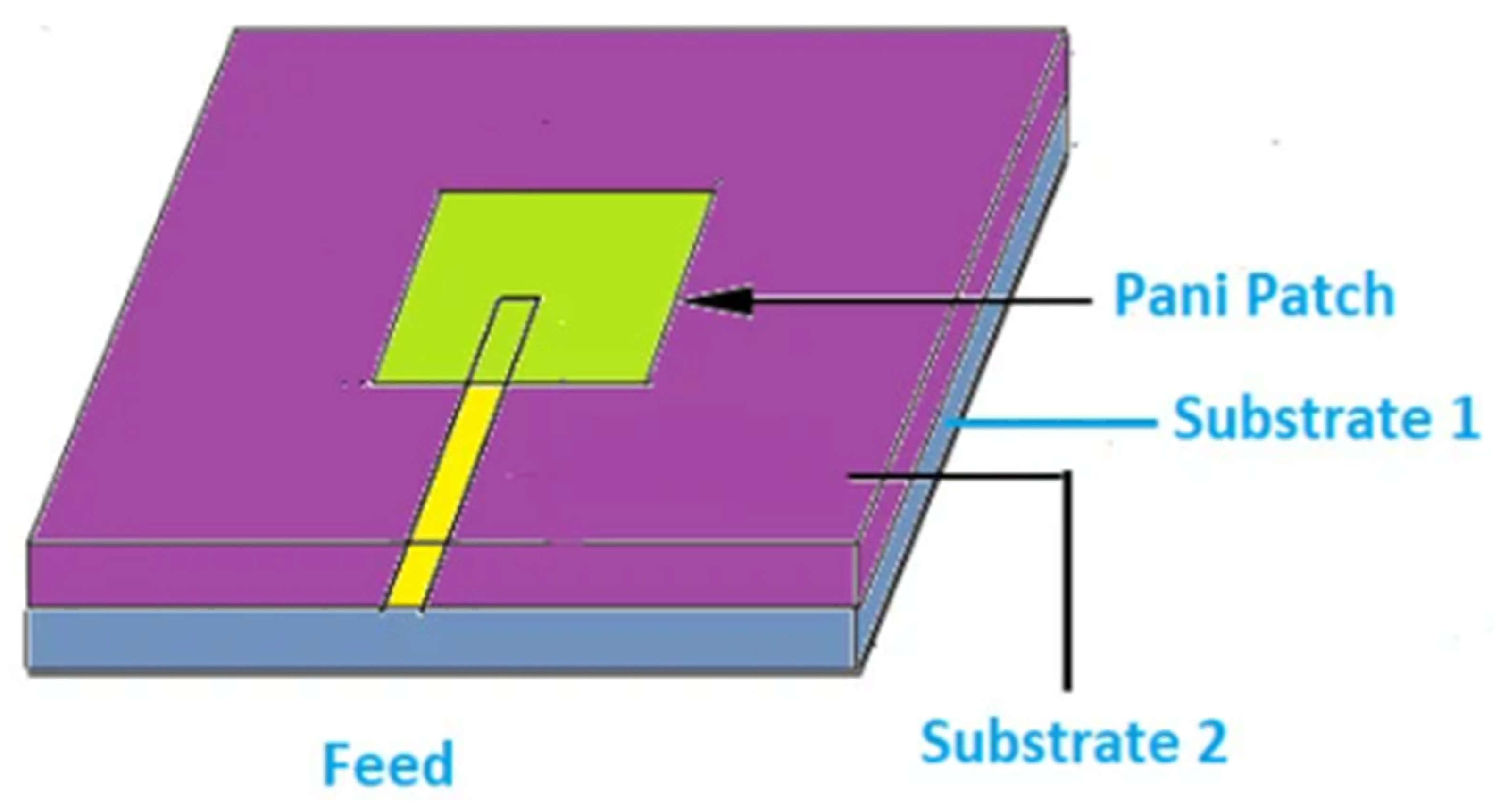
Transparent substrates extend beyond conventional glass to include materials such as polymers, conductive oxides, and flexible films that enable both optical transparency and electromagnetic functionality. Common options include polyethylene terephthalate (PET), polycarbonate, and ITO-coated films, which typically exhibit low dielectric constants and relatively low loss at microwave frequencies [62]. These properties make them attractive for lightweight, flexible, and conformal antenna designs. A conductive polymer microstrip-fed patch antenna operating at 10 GHz was proposed in [63], using polyaniline (PANI) as the radiating film (conductivity ≈ 6 × 10³ S/m, thickness 100 µm). The design achieved a gain of 2.08 dB, as shown in Figure 1.

4.3. Multi-Layer Wall Structures

Modern building walls typically comprise multiple layers with distinct electromagnetic properties: exterior cladding, insulation, vapor barriers, structural elements, and interior finishes. Each layer contributes to the overall transmission loss, and the interfaces between layers create impedance discontinuities that generate reflections. The cumulative effect can result in signal attenuation exceeding 20–30 dB, severely degrading indoor cellular coverage [64].
A novel semi-analytical technique was introduced for analyzing multi-layered walls with periodic interfaces, providing a simplified and validated approach to evaluate scattering characteristics and examine the influence of structural parameters [65]. In addition, a comprehensive MATLAB-based multilayer electromagnetic simulation tool was developed to facilitate the analysis of RF transparency in building walls. This tool enables the evaluation of different material configurations, integration of advanced components such as frequency selective surfaces (FSS), and assessment of overall frequency response [66]. Furthermore, the modal transmission-line (MTL) method was applied to analyze the transmission coefficient of building walls, which is essential for accurate microcellular network planning. By modeling walls as multilayer periodic structures, this method allows detailed investigation of radiowave propagation through complex environments, with its accuracy validated through comparison with finite-element method results reported in the literature [67].
The design process required simultaneous consideration of electromagnetic and thermal performance, as modifications to improve RF transmission (e.g., creating apertures or reducing insulation thickness) could degrade thermal insulation. Electromagnetic-thermal co-simulation enabled identification of antenna geometries and positions that satisfied both requirements [68]. The resulting signal-transmissive wall maintained the thermal insulation properties of the original structure while dramatically improving indoor connectivity, demonstrating the feasibility of dual-function building elements.
Passive antenna systems embedded in walls at 35 GHz have also been investigated for 5G millimeter-wave applications. Two-patch and four-patch configurations operating around 3.5 GHz were studied, with numerical simulations showing that these antenna systems enhance the transmission coefficient of typical building walls [69]. The four-patch design maintained thermal insulation performance while improving RF transmission, although higher-frequency operation introduces additional challenges related to fabrication tolerances and variations in material properties.

4.4. Comparative Material Analysis

The literature reveals systematic differences in how various building materials impact antenna performance, though comprehensive comparative studies across multiple materials remain limited. Table 2 provides a consolidated comparison of building material impacts on antenna performance, highlighting key electromagnetic properties, quantitative performance degradation, underlying physical mechanisms, and corresponding mitigation strategies.

5. Concealment Technologies and Design Approaches

5.1. Transparent Conductive Oxide Antennas

TCOs enable antenna fabrication with optical transmittance exceeding 70–90%, making them suitable for window integration and applications where visual transparency is paramount [70,71,72]. The two most widely studied TCO materials for antenna applications are ITO and GZO, each offering distinct trade-offs in conductivity, transparency, cost, and fabrication complexity. ITO generally provides higher conductivity, with a sheet resistance of 10–30 Ω/square, compared to 30–50 Ω/square for GZO. This results in improved electromagnetic performance, albeit with slightly reduced optical transparency and higher material cost [73,74].
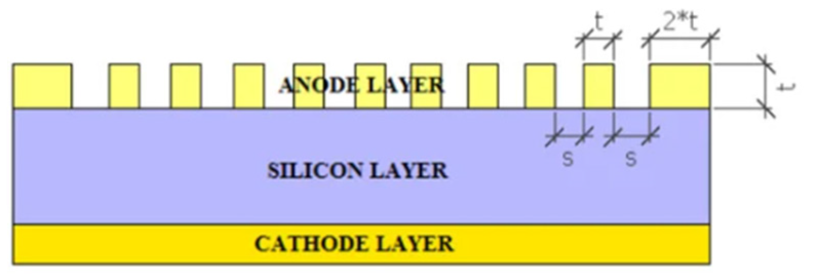
The analysis of a 28 GHz solar patch antenna that utilizes variations of TCOs thin films, including ITO, Fluorine-doped Tin Oxide (FTO), Silver-coated AgHT-4, and AgHT-8, used as the radiating patch [75] as shown in Figure 2. These materials are tested with glass as the substrate as the radiating patch. This approach aims to overcome the problem of traditional, non-transparent radiating patches shadowing the solar cell and degrading its efficiency.
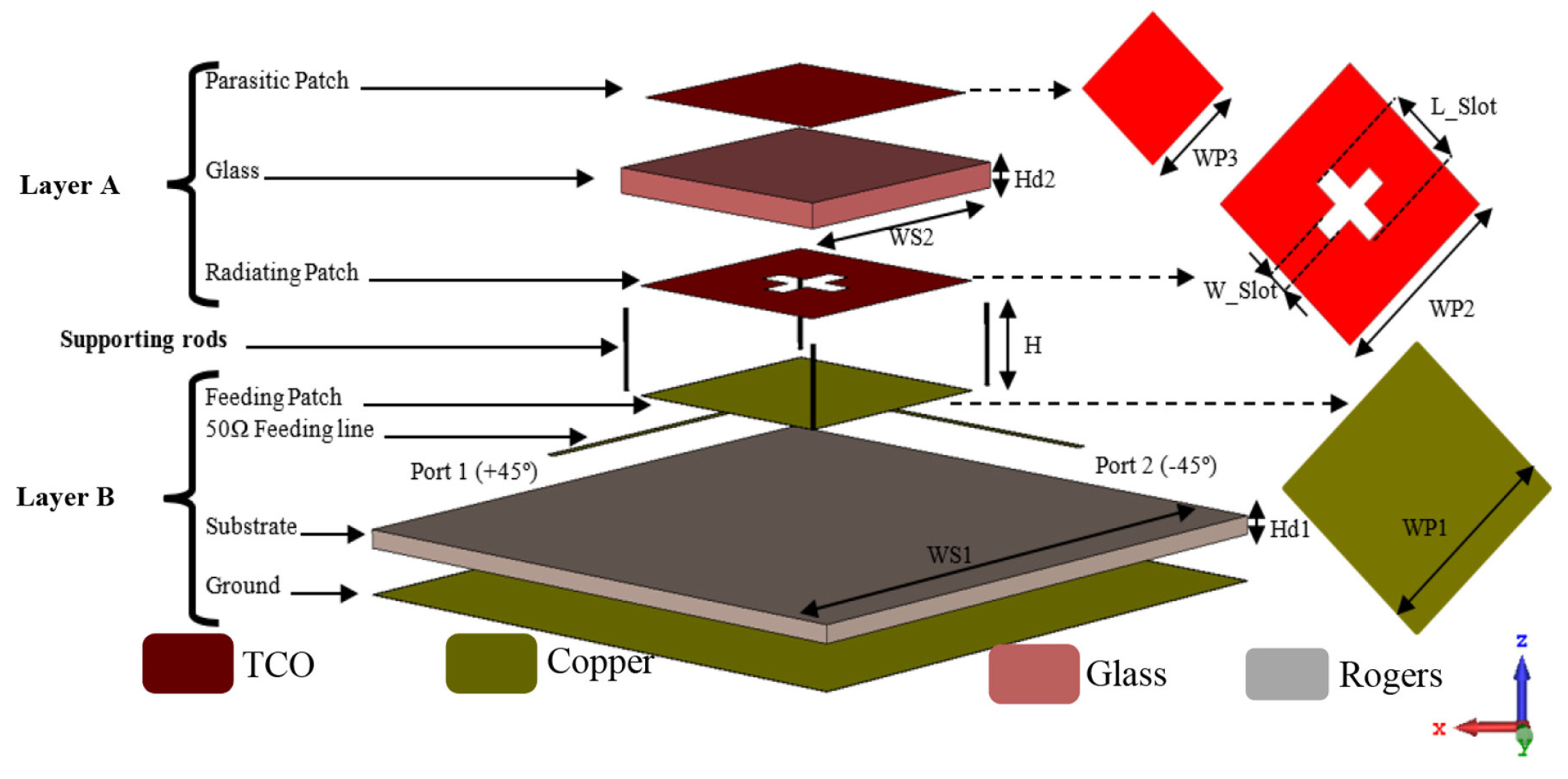
ITO-based transparent antennas as shown in Figure 3 for 5G pico-cell base stations have been demonstrated, achieving 77% visual transparency while maintaining a realized gain of 13.2 dBi in a 2 × 2 array configuration [5]. The radiating layer comprised ITO patches printed on opposite sides of a glass laminate, with the feeding network embedded within a street lamp head for effective concealment. The system exhibited favorable reflection coefficient characteristics, indicating that ITO can support practical 5G deployments when implemented in optimized array configurations.
GZO offers advantages in terms of material abundance (avoiding the supply constraints of indium) and potentially lower cost, though typically at the expense of higher sheet resistance. Detailed comparative studies of GZO and copper antennas revealed that a single GZO element achieved approximately 8% efficiency and a gain of −10.87 dBi, compared to 2.18 dBi for a copper counterpart [6]. However, a 4 × 1 GZO array improved the gain to 0.34 dBi, demonstrating that array configurations can partially mitigate the limitations associated with lower conductivity. In addition, the GZO elements exhibited a simulated operational band from 2.8 GHz to 10 GHz (112.5% fractional bandwidth), which is significantly broader than that of copper elements (5.67–6.62 GHz, 7.6% bandwidth), primarily due to resistive damping that reduces the resonance quality factor.
Systematic reviews of transparent antenna technologies have identified key design principles for TCO-based systems [72]. Optical transparency and electrical conductivity are fundamentally coupled through the material’s electronic band structure, creating an unavoidable tradeoff. Increasing film thickness or doping concentration improves conductivity but reduces transparency. Practical designs must balance these competing requirements based on application-specific priorities. For smart city and IoT applications where moderate performance is acceptable, transparency may be prioritized; for pico-cell base stations requiring higher gain, conductivity takes precedence [76].
Fabrication techniques for TCO antennas include sputtering, chemical vapor deposition, and solution-based processes, each with distinct implications for film quality, uniformity, and cost. Patterning can be achieved through photolithography, laser ablation, or shadow masking. The choice of fabrication method impacts the achievable sheet resistance, transparency, and minimum feature size, which in turn constrain the antenna designs that can be realized [77].
Table 3 summarizes the typical ranges of sheet resistance and optical transmittance reported in the literature. The values presented reflect variations in fabrication methods, film thickness, doping levels, and measurement conditions. The table highlights the inherent trade-offs between electrical conductivity and optical transparency, which fundamentally govern the performance of transparent antenna systems. This comparison provides a unified framework for selecting appropriate materials based on application-specific requirements in transparent and concealed antenna design.

5.2. Antenna-on-Glass Integration

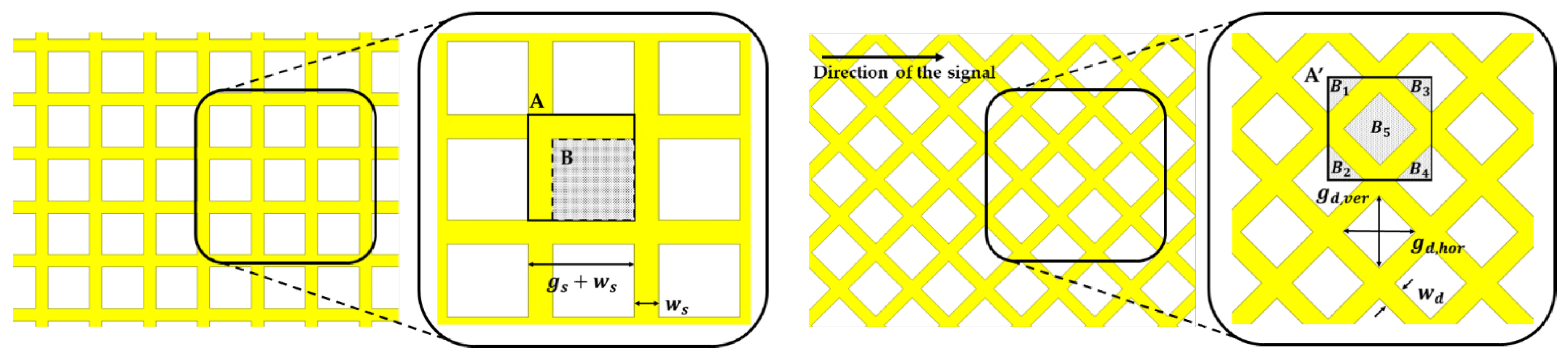
Antenna-on-glass integration encompasses a broader range of techniques beyond TCO-based designs, including meshed metal conductors, grid antennas, and hybrid approaches that combine transparent and opaque elements [83,84,85]. These methods offer different points on the transparency-performance tradeoff curves enabling designers to select approaches matched to specific application requirements. Figure 4 presents the design parameters of square and diamond mesh configurations, illustrating their respective geometries and their impact on the performance of fully meshed antennas and integrated feedlines.
Meshed conductor antennas achieve optical transparency by employing thin metallic traces, typically copper or silver, arranged in grid or mesh patterns with open areas that permit light transmission. A novel fabrication approach has been introduced to realize optically transparent, flexible, and conformal antennas, addressing the challenge of simultaneously achieving high electrical conductivity and optical transmittance. Using this method, metallic meshes with optical transmittance exceeding 90% were successfully fabricated, with tunable sheet resistance reduced to approximately 2 Ω/square. The resulting antennas demonstrated optical transmittance levels of 92% and 55% for different design configurations, while maintaining effective radio-frequency performance [86].
Grid antennas represent a specialized class of meshed designs in which the conductor pattern itself functions as the radiating structure. Glass-integrated grid antennas have been developed using characteristic mode analysis (CMA) for multiband indoor network applications [87]. The grid topology inherently supports multiband operation by exciting different characteristic modes at distinct frequencies, while preserving visual transparency through its open structure. This approach is particularly well suited for indoor coverage scenarios, where moderate gain and multiband capability are often prioritized over maximum radiation efficiency.
Coplanar waveguide (CPW) antennas on glass offer advantages for millimeter-wave applications where the ground plane and signal traces can be patterned on the same surface, simplifying fabrication and enabling integration with active components. Ibrahim et al. demonstrated CPW antennas on glass for 5G and beyond, showing that this topology can achieve acceptable gain and pattern characteristics for mmWave frequencies while maintaining aesthetic integration [88]. The CPW configuration also provides inherent wideband matching characteristics, which is beneficial for supporting multiple 5G bands.
For window-type transparent antenna systems targeting beyond-5G and 6G applications, relevant deployment scenarios have been proposed using antennas that combine high electrical conductivity with high optical transparency for in-building networks and mmWave augmented reality systems [4]. These systems were evaluated through software-defined radio implementations and system-level simulations, demonstrating their feasibility for future deployment. A key aspect of this approach is the use of advanced transparent conductive materials or hybrid conductor designs that offer improved conductivity–transparency trade-offs compared to conventional ITO or GZO, although the specific material compositions were not fully disclosed.

5.3. Structural Embedding in Walls

Structural embedding involves integrating antennas directly into load-bearing walls, insulation layers, or other building structural elements, providing complete visual concealment at the cost of more severe electromagnetic challenges [89,90]. This approach is motivated by applications requiring permanent installation, protection from environmental factors, or situations where even transparent antennas would be visually unacceptable.
The signal-transmissive wall concept represents one of the most comprehensive approaches to structural embedding [91]. Related studies on 5G mobile devices have focused on characterizing antenna radiation in the presence of human hands, highlighting the significant impact of user interaction on mmWave signal performance. It has been shown that natural grip positions can substantially alter antenna coverage on the device chassis, with even minor variations in hand placement leading to noticeable changes in radiation characteristics. To address this, a method for generating accurate 3D models of human hands has been developed for analyzing antenna–hand interactions in mobile devices. This approach is particularly important, as mmWave signals are far more susceptible to blockage and attenuation from the user’s hand compared to conventional sub-6 GHz systems.
For millimeter-wave frequencies, passive antenna systems embedded in walls face additional challenges related to higher material losses and tighter fabrication tolerances [92]. Two-patch and four-patch configurations for signal-transmissive walls have been investigated to enhance electromagnetic transmission through energy-efficient wall structures while preserving thermal insulation performance [2]. Numerical simulations, typically conducted using tools such as CST Studio Suite, demonstrate that these antenna-integrated designs can significantly improve wall transmission coefficients at frequencies relevant to 5G systems. Among the configurations, the four-patch design exhibits superior performance compared to the two-patch arrangement, primarily due to higher aperture efficiency and a more uniform field distribution across the wall cross-section.
Embedding antennas for structural health monitoring represents a distinct application where the antenna serves dual purposes: wireless communication and sensing of the structure’s condition. RF energy-powered sensor nodes have been developed with antennas embedded directly in concrete, protected by epoxy resin to withstand the highly alkaline environment [39]. The antennas were printed on the underside of the circuit board and designed to operate under severe material loading and the time-varying properties associated with concrete curing. In this context, lower antenna performance is acceptable compared to conventional communication systems, as the primary requirement is maintaining a sufficient link budget for short-range interrogation rather than achieving high data rates or wide coverage.

5.4. Camouflage and Low-Visibility Designs

Camouflage and low-visibility antenna designs aim to integrate radiating structures seamlessly into their surrounding environment without compromising electromagnetic performance [93,94]. These approaches are increasingly important for smart infrastructure, where antennas are embedded into architectural elements such as walls, windows, lighting fixtures, and façades to avoid visual clutter while supporting dense wireless connectivity. By leveraging transparent conductive materials, textured surfaces, and structurally integrated layouts, antennas can be concealed within everyday objects while still maintaining acceptable radiation characteristics.
A key design challenge lies in balancing aesthetic invisibility with electrical performance. Techniques such as frequency selective surfaces, grid and mesh conductors, and transparent conductive oxides enable partial or near-complete optical transparency, allowing antennas to blend with glass or coated substrates. At the same time, embedding antennas into building materials introduces additional complexities such as dielectric loading, detuning effects, and angle-dependent transmission variations, which must be carefully managed through simulation-driven optimization.
Overall, camouflage antenna systems represent a convergence of electromagnetics and architectural design, enabling unobtrusive wireless coverage for next-generation smart environments, including 5G and beyond applications.

5.5. Metasurface-Enhanced Windows

Metasurface-enhanced windows represent an advanced approach to integrating electromagnetic functionality into transparent architectural elements. By incorporating engineered subwavelength structures onto or within glass surfaces, these metasurfaces can manipulate incident electromagnetic waves in a controlled manner, enabling functions such as beam focusing, redirection, filtering, or signal enhancement while preserving optical transparency. This makes them particularly attractive for modern buildings, where conventional materials often attenuate wireless signals due to coatings or multilayer configurations.
Metasurfaces, defined by their subwavelength periodic structures, provide a distinct alternative to traditional antenna-based solutions. Instead of generating electromagnetic radiation through current flow, they operate passively by modifying incident waves via tailored scattering, refraction, or focusing effects. This enables improved signal transmission through windows without requiring visibly conductive antenna elements, thereby maintaining architectural aesthetics.
A metasurface-integrated glass design has been demonstrated to simultaneously provide low-emissivity thermal insulation and enhanced 5G signal propagation [50]. In this approach, the outer surface incorporates a metasurface that reflects infrared radiation for thermal management while allowing visible light transmission. At the same time, the metasurface unit cells are engineered to focus sub-6 GHz 5G signals, achieving signal enhancement exceeding 10 dB within a 150 mm region around the focal point and more than 15 dB at the focal point itself. Real-world building measurements further show improvements in reference signal received power (RSRP) of 6–9 dB compared to conventional glass, confirming the practical viability of this concept.
Compared to transparent conductor antennas, the metasurface approach offers several advantages. It does not require active feeding or impedance matching networks, simplifying installation and reducing potential points of failure. In addition, metasurfaces can be designed for relatively wide bandwidth operation using multi-resonant unit cells or gradient configurations. They can also support multifunctionality, enabling simultaneous thermal insulation, signal enhancement, and potentially solar control or privacy features through careful design.
Surface-mount passive metasurfaces have also been explored for enhancing microwave transmission through window glass in 5G and 6G applications [31]. This approach enables retrofitting of existing windows without replacement, providing a practical pathway for upgrading building infrastructure. By minimizing reflection and maximizing transmission at target frequencies, such designs effectively create frequency-selective windows that remain optically transparent while improving wireless connectivity.
Closely related to metasurfaces, FSS consist of periodic arrays of metallic patches or apertures embedded into or applied onto glass. These structures can be tailored to selectively transmit or block specific frequency bands, enabling applications such as electromagnetic shielding while maintaining connectivity for designated signals [95]. However, experimental validation of FSS-based concealment in real building environments remains limited, highlighting an important direction for future research.

5.6. Multi-Band Concealed Antenna

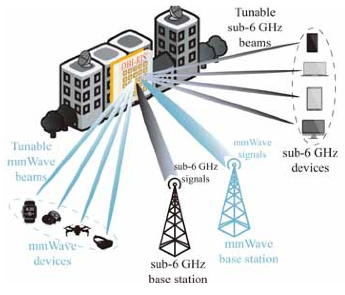
For multi-band concealed antenna systems targeting both sub-6 GHz and mmWave operation, a shared-aperture design strategy is generally preferred to achieve compact integration while maintaining electromagnetic isolation between bands [96,97]. In such architectures, low-frequency elements (e.g., patch, monopole, or slot antennas) are co-located with high-frequency arrays or metasurface-based radiating layers within the same physical footprint, enabling simultaneous operation without significant aperture enlargement. Complementary element approaches are often employed, where sub-6 GHz radiation is handled by electrically larger structures, while mmWave functionality is realized using subwavelength or phased-array elements embedded within the same substrate or layered structure. Electromagnetic isolation is typically enhanced through the use of frequency-selective surfaces, defected ground structures, or electromagnetic bandgap patterns, which suppress inter-band coupling and stabilize impedance characteristics. Simulation studies reported in the literature indicate that such isolation techniques can preserve sub-6 GHz radiation efficiency while enabling efficient mmWave beam steering with limited mutual interference [98]. Overall, shared-aperture and complementary element designs provide a practical pathway for realizing compact, multi-functional concealed antennas suitable for integrated 5G and beyond communication systems (Figure 5).
Table 4 summarizes the key concealment technologies and design approaches discussed in this section, highlighting their operational principles, performance characteristics, and associated trade-offs. TCO-based antennas offer the highest optical transparency but exhibit significant efficiency degradation due to high sheet resistance, necessitating array configurations or hybrid designs to improve gain. Antenna-on-glass techniques, including meshed and grid conductors, provide a more balanced trade-off between transparency and conductivity, enabling practical implementations with moderate performance.
Structural embedding approaches achieve complete visual concealment and environmental protection; however, they introduce severe dielectric loading and material-induced losses, making them more suitable for short-range or sensing applications rather than high-performance communication systems. Camouflage and low-visibility designs extend integration into architectural elements but require careful electromagnetic optimization to mitigate detuning and radiation distortion. In contrast, metasurface-enhanced windows provide a passive solution for improving signal transmission and coverage, offering additional multifunctional benefits such as thermal insulation without requiring active feeding networks.
Overall, the table illustrates that the selection of a concealment technique depends strongly on the target application, required electromagnetic performance, and acceptable level of visual integration.
Table 5 summarizes the key reported performance metrics along with their corresponding test conditions, including frequency, material environment, antenna configuration, and evaluation method. This compilation highlights the variability in measurement and simulation setups across the literature and provides a structured basis for interpreting reported results such as gain, efficiency, transmission improvement, and resonant frequency shift.

6. Applications and Use Cases

6.1. 5G and Beyond-5G Cellular Networks

Fifth-generation (5G) cellular networks, along with emerging beyond-5G (B5G) and sixth-generation (6G) systems, represent the primary drivers for the development of concealed antenna technologies. The high densification requirements of 5G, with inter-site distances potentially falling below 100 m in dense urban environments, create a strong need for aesthetically unobtrusive antenna solutions that can be deployed at street level, integrated into building façades, or embedded within indoor spaces [99].
For sub-6 GHz 5G bands, particularly in the 3.3–3.8 GHz range, transparent and camouflaged pico-cell base stations enable dense network deployment without introducing visual clutter [5]. By integrating antennas into materials such as glass, walls, or street infrastructure, these systems can maintain urban aesthetics while delivering reliable coverage and capacity in high-demand areas. In addition, recent work has introduced a swarm intelligence-based meta-heuristic algorithm for optimizing 5G mmWave base station deployment [100]. The approach incorporates redundant base station removal and a comprehensive optimization framework to improve network efficiency. Its effectiveness is demonstrated through comparative analysis, showing enhanced coverage, reduced outage probability, and faster computational performance relative to conventional methods. Specifically, the algorithm minimizes the number of required base stations while optimizing their placement at mmWave frequencies, such as 28 GHz and 38 GHz, ensuring that user data rate requirements are satisfied.
A comprehensive review of mmWave enabling technologies that are critical for 5G and future 6G wireless communication systems [101]. It highlights recent developments while outlining the key requirements and challenges associated with next-generation networks. Particular emphasis is placed on advancements in beamforming integrated circuits (ICs) for both hybrid massive MIMO and asymmetrical massive MIMO architectures. The study further identifies the evolving demands of 6G systems, including the need for highly integrated transceiver channels, wider operating frequency bands, increased operational flexibility, and support for diverse functionalities beyond those of current 5G technologies.

6.2. Internet of Things and Smart Cities

Internet of Things (IoT) deployments and smart city applications require ubiquitous wireless connectivity for distributed sensors, actuators, and edge computing devices [102]. Concealed antennas enable IoT infrastructure integration into urban furniture, building facades, and public spaces without creating visual clutter or requiring dedicated mounting structures [103].
In smart city scenarios, concealed antennas are particularly valuable for supporting low-power wide-area network (LPWAN) technologies such as Long Range Wide Area Network (LoRaWAN), Narrowband-IoT (NB-IoT), and Sigfox, which are widely used for applications including environmental monitoring, smart metering, traffic management, and public safety systems [104]. These applications typically require long-range communication with low data rates, making it feasible to integrate antennas into infrastructure elements such as lamp posts, utility boxes, and signage. Such integration not only improves network coverage and reliability but also enhances system scalability by enabling dense and unobtrusive deployment.
Furthermore, the integration of concealed antennas with edge computing and intelligent sensing platforms enables real-time data processing and decision-making in smart cities [105]. Embedding antennas within buildings and urban infrastructure supports localized communication between devices and edge nodes, reducing latency and improving overall system efficiency. However, challenges remain in terms of electromagnetic interference, material-induced signal attenuation, and maintenance accessibility, which must be addressed through careful design and optimization of antenna placement and surrounding materials.
The integration of transparent antennas into building windows creates opportunities for distributed antenna systems that provide uniform coverage across urban areas. Each window can function as a small cell or IoT gateway, creating a dense network of access points without requiring dedicated infrastructure. This approach is particularly valuable in dense urban environments where traditional tower-based infrastructure cannot provide adequate coverage due to building blockage and where aesthetic concerns limit deployment of visible antennas [106].

6.3. Structural Health Monitoring

SHM of civil infrastructure represents a specialized application in which antennas are permanently embedded in materials such as concrete, steel, or composites to enable wireless interrogation of sensors that monitor parameters including stress, strain, temperature, moisture, and chemical conditions. In this context, lower antenna performance can be tolerated compared to conventional communication systems, as the primary requirements are maintaining a sufficient link budget for short-range communication and ensuring long-term reliability in harsh environments [107,108].
Recent research has focused on the development of robust embedded antenna systems capable of operating under severe material loading and environmental variability. Factors such as high permittivity, moisture content, and curing processes in concrete can significantly detune antennas and reduce radiation efficiency. To address these challenges, studies have explored miniaturized antenna designs, encapsulation techniques, and frequency tuning strategies that compensate for dielectric variations over time, ensuring stable performance throughout the lifecycle of the structure [55,109].
In addition, energy-efficient and battery-free SHM systems have gained increasing attention, particularly those based on RF energy harvesting or passive RFID technologies. These systems eliminate the need for frequent maintenance or battery replacement, making them well suited for long-term deployment in inaccessible or hazardous locations. Embedded antennas play a critical role in enabling reliable wireless power transfer and data communication, even in highly attenuative environments such as reinforced concrete [110,111].
Furthermore, advancements in wireless sensing networks and data analytics have enhanced the capabilities of SHM systems by enabling real-time monitoring and predictive maintenance. The integration of embedded antennas with distributed sensor networks allows continuous data acquisition and transmission to centralized or edge-based processing units. This facilitates early detection of structural anomalies, reduces maintenance costs, and improves overall safety and resilience of infrastructure systems, although challenges related to signal attenuation, interference, and scalability remain active areas of research [112,113].

6.4. Indoor Coverage Enhancement

Indoor cellular coverage has become increasingly critical as mobile data traffic continues to shift toward indoor environments, with estimates indicating that approximately 70–80% of usage occurs indoors [114]. However, modern building materials, particularly energy-efficient walls with multilayer insulation and low-emissivity windows, introduce significant signal attenuation, leading to degraded indoor coverage and reduced quality of service.
To address these challenges, a range of solutions has been explored, including distributed antenna systems (DAS), small cells, and signal repeaters [115]. While effective, these approaches often require additional infrastructure, increased deployment costs, and complex installation. As an alternative, concealed and integrated antenna systems embedded within walls, windows, or ceilings have emerged as a promising approach to enhance indoor signal penetration without compromising building aesthetics.
Recent research has also focused on the use of signal-transmissive materials and metasurface-based designs to improve electromagnetic wave propagation into indoor spaces [116,117]. These technologies can reduce reflection and absorption losses at building interfaces, enabling better signal penetration from outdoor base stations. In addition, transparent antennas and frequency-selective surfaces integrated into windows can selectively enhance desired frequency bands, further improving indoor coverage while maintaining energy efficiency.
Furthermore, hybrid approaches that combine passive and active techniques are gaining attention for next-generation indoor networks [118]. For example, integrating concealed antennas with intelligent reflecting surfaces or reconfigurable metasurfaces allows dynamic control of signal propagation, optimizing coverage based on user distribution and environmental conditions. Despite these advancements, challenges such as material compatibility, cost, and large-scale deployment remain key areas for ongoing research.
Table 6 presents a comparative overview of the major application domains of concealed antenna systems, linking each use case with its corresponding frequency range, performance requirements, and implementation challenges. In 5G and beyond-5G networks, concealed antennas enable dense deployment of pico-cell and millimeter-wave systems, where high gain, beamforming capability, and optimized placement are critical for overcoming propagation losses and blockage.
For IoT and smart city applications, the emphasis shifts toward scalability, low power consumption, and unobtrusive integration into urban infrastructure, where moderate antenna performance is acceptable. Structural health monitoring represents a distinct use case in which antennas are embedded within materials such as concrete, requiring robust operation under severe dielectric loading and environmental variability, often prioritizing reliability over efficiency.
Indoor coverage enhancement applications focus on mitigating signal attenuation caused by modern building materials, with concealed antennas and metasurface-based solutions improving signal penetration and coverage uniformity without additional visible infrastructure. The table further highlights that each application domain imposes unique design constraints, reinforcing the need for application-specific optimization of antenna configuration, materials, and placement strategies.

7. Discussion

7.1. Design Tradeoffs and System-Level Optimization

The reviewed literature consistently demonstrates that concealed antenna systems are governed by unavoidable multi-domain tradeoffs spanning electromagnetic, material, architectural, and system-level constraints. These tradeoffs must be addressed through integrated design frameworks rather than isolated antenna optimization.
Transparency versus Conductivity: For transparent antennas, optical transmittance and electrical conductivity remain fundamentally coupled. Materials such as ITO and GZO illustrate this limitation, where higher conductivity improves radiation efficiency but reduces transparency and increases cost. Emerging materials such as graphene, silver nanowires, and hybrid metal–oxide films attempt to shift this tradeoff frontier, but practical implementations still face scalability and durability challenges. From a system perspective, acceptable transparency thresholds (typically 70–90%) should be defined at the application level, followed by electromagnetic optimization within those constraints.
Embedding Depth versus Electromagnetic Performance: Embedding depth strongly influences path loss, impedance matching, and radiation efficiency. Experimental studies show attenuation exceeding 80 dB in high-moisture concrete, highlighting the extreme sensitivity to material conditions. Optimal strategies include shallow embedding, dielectric buffering layers, and electromagnetic pre-compensation. In addition, co-design with building materials, including low-loss insulation layers or engineered interfaces, can significantly reduce attenuation.
Bandwidth versus Efficiency Tradeoff: Transparent conductors and lossy environments inherently broaden impedance bandwidth due to reduced quality factor, but at the expense of efficiency. This creates application-dependent design decisions: wideband operation is advantageous for multi-band 5G/6G systems, whereas high-efficiency narrowband designs are preferred for energy-constrained IoT and SHM applications.
Array Size versus Esthetic Integration: Array configurations provide the most effective mechanism for recovering gain losses, with improvements proportional to element count. However, larger arrays reduce transparency and increase physical footprint. Advanced solutions such as sparse arrays, non-uniform spacing, and beamforming architectures can improve gain per unit area while preserving visual integration.
System-Level Tradeoff: A key insight across Section 1, Section 2, Section 3, Section 4, Section 5 and Section 6 is that antenna performance cannot be optimized independently of network-level requirements. For example, reduced antenna gain can be compensated through network densification, beamforming, or RIS-assisted propagation. Thus, future design should adopt joint antenna–network optimization frameworks, particularly for 5G/6G deployments.

7.2. Performance Recovery Techniques

Several techniques have been proposed to mitigate performance degradation due to concealment, though none fully eliminate the inherent limitations.
Array-Based Gain Recovery: Array configurations remain the most effective approach for compensating low conductivity and embedding losses. Experimental results show gain improvements exceeding 10 dB through arraying, enabling practical deployment in pico-cell systems. However, challenges such as feed network losses, mutual coupling, and increased system complexity must be addressed.
Adaptive and Intelligent Matching Networks: Dynamic impedance matching offers a promising solution for environments with time-varying properties, such as curing concrete or temperature-dependent materials. Emerging approaches using tunable components and AI-assisted impedance tuning can maintain optimal matching conditions in real time.
Wideband and Multi-Resonant Designs: Spiral, log-periodic, and characteristic mode-based antennas provide robustness against frequency detuning caused by material loading. These designs are particularly suitable for multi-band and future-proof communication systems.
Metasurface and RIS-Based Enhancement: Metasurfaces and reconfigurable intelligent surfaces (RIS) introduce a paradigm shift by modifying propagation rather than radiation. These structures can improve signal penetration, reduce blockage, and enhance indoor coverage without requiring active antenna elements. Their integration with concealed antennas enables hybrid passive-active systems with improved performance.
Material and Fabrication Innovations: Advances in nanomaterials, printable electronics, and flexible substrates are gradually improving conductivity-transparency tradeoffs and enabling scalable manufacturing. Techniques such as electrohydrodynamic lithography and inkjet printing offer promising pathways for large-area deployment.

7.3. Limitations of Current Approaches

Despite significant progress, several limitations constrain the practical deployment of concealed antenna systems:
Performance Gaps: Even optimized concealed antennas exhibit 5–15 dB lower gain compared to conventional metallic designs, limiting their applicability in high-power or long-range communication systems.
Material Property Uncertainty: Building materials exhibit large variability in dielectric properties due to moisture, temperature, and aging. This introduces uncertainty in antenna performance and complicates design standardization.
Fabrication Challenges: Transparent antennas require specialized fabrication processes, while embedded systems demand coordination with construction workflows. These practical constraints hinder large-scale adoption.
Limited Multi-Band Operation: Achieving efficient multi-band operation across sub-6 GHz and mmWave frequencies remains challenging due to increased losses and fabrication tolerances at higher frequencies.
Lack of Standardization: There is currently no unified framework for evaluating concealed antennas in terms of electromagnetic, optical, and structural performance. Standardized testing methodologies are essential for commercialization and industry adoption.
Long-Term Reliability: Long-term durability under environmental stress, including UV exposure, humidity, and mechanical strain, remains insufficiently studied. This is particularly critical for building-integrated systems with lifetimes exceeding 20 years.
At present, no dedicated international standard exists for evaluating building-integrated metasurfaces or signal-transmissive wall systems. Consequently, most studies adopt established antenna measurement practices, particularly IEEE Std 149 [119], along with conventional anechoic chamber techniques for near-field and far-field characterization. Experimental validation of metasurface-enhanced windows is typically conducted in controlled indoor environments using horn antennas or vector network analyzers, with measurement distances satisfying far-field criteria (2D2/λ) and sample sizes representative of practical window apertures (approximately 0.1–1 m2) [120,121]. Similarly, signal-transmissive wall investigations commonly utilize scaled or full-thickness multilayer samples evaluated under normal and oblique incidence in calibrated free-space or semi-anechoic setups [122]. However, several limitations remain. Laboratory samples are often smaller than real building structures, which may underestimate edge diffraction, environmental scattering, and multipath effects. In addition, many studies assume idealized plane-wave excitation, whereas real-world propagation conditions are angular and dynamic. Furthermore, material heterogeneity in practical construction, such as reinforcement in concrete or coating variability in glass, is not always fully captured in controlled experiments, limiting direct generalization of reported performance metrics. These factors highlight that, although current methodologies are consistent with conventional antenna testing approaches, the development of standardized evaluation protocols specifically tailored to building-integrated electromagnetic systems remains an important open research challenge.
In mmWave and Ka-band concealed antenna implementations, fabrication tolerances play a critical role due to the electrically small wavelength, where minor dimensional deviations can significantly affect electromagnetic performance [92,123,124]. Typical manufacturing variations on the order of ±10–50 µm in patch dimensions, slot widths, or mesh periodicity can introduce resonant frequency shifts of approximately 1–5% and phase errors that accumulate across array elements, leading to beam pointing deviations, increased side-lobe levels, and reduced array gain. These effects are further exacerbated in transparent conductive oxide and metasurface-based designs, where additional variability in sheet resistance, film uniformity, and unit cell geometry contributes to impedance mismatch and phase distortion. To mitigate these issues, tolerance-aware design methodologies are commonly employed, including full-wave parametric sensitivity analysis during optimization, use of wideband or low-Q antenna geometries to reduce frequency sensitivity, and incorporation of redundant or subwavelength metasurface unit cells to average out local fabrication errors. At the array level, calibration techniques and phase compensation networks can also be applied to correct residual element-to-element variations, improving beam stability and overall radiation performance in practical concealed antenna deployments at high frequencies.
From a commercialization perspective, the primary limiting factors for concealed antenna technologies are manufacturing cost and process scalability, followed by fabrication complexity, while maintainability is a secondary but still relevant constraint. High-performance transparent and embedded antenna systems often rely on expensive materials such as indium-based oxides, silver nanowires, or precision-engineered meshed conductors, which significantly increase production cost and restrict large-scale deployment. In addition, fabrication processes typically require high-resolution lithography, controlled deposition techniques, or multilayer integration, which introduce yield limitations and increase manufacturing complexity [125,126]. These challenges are further amplified when antennas are integrated into building materials such as glass or concrete, where alignment precision and structural compatibility must also be maintained. Although maintainability is less critical during initial deployment, long-term performance can be affected by environmental degradation, material aging, and limited accessibility for repair or replacement, particularly in embedded or façade-integrated configurations [127]. To address these limitations, recent studies propose the use of low-cost alternative materials such as metal meshes [126,128] or graphene-based films [129,130,131], adoption of scalable roll-to-roll and printing fabrication techniques [132], and modular or replaceable antenna architectures that improve repairability and lifecycle management [133,134,135].
Long-term reliability of concealed and building-integrated antenna systems remains an important but relatively underexplored aspect, as most reported studies focus on short- to medium-term performance (days to months), with only limited multi-year field data available. Consequently, reliability is typically evaluated using accelerated aging methodologies that simulate environmental stress conditions such as temperature cycling, high humidity exposure (e.g., 85 °C/85% RH), UV radiation, and mechanical stress, following general electronic testing practices (e.g., IEC 60068 [136]). The dominant degradation mechanisms depend on the material system: TCO antennas are prone to increased sheet resistance due to microstructural changes, thermal-induced cracking, and moisture ingress [137,138]; silver nanowire and meshed conductors are affected by oxidation and junction resistance growth; while metasurface-based and embedded wall systems are more susceptible to substrate aging, mechanical deformation, and detuning caused by variations in surrounding dielectric properties such as moisture in concrete or delamination in multilayer structures [120]. To ensure long-term performance stability, it is recommended that accelerated aging tests be combined with periodic electromagnetic characterization, including S-parameter monitoring, gain stability, and radiation pattern evaluation, enabling estimation of performance drift over extended operational lifetimes. Establishing standardized reliability benchmarks for such systems remains an open research challenge for large-scale deployment in future wireless infrastructure.

8. Future Research Directions

8.1. Advanced Materials and Fabrication

The development of next-generation materials with improved conductivity–transparency characteristics remains a key research priority for concealed antenna systems. Current transparent conductive oxides are fundamentally limited by the inverse relationship between electrical conductivity and optical transmittance, motivating the exploration of alternative materials and hybrid approaches.
Graphene and Carbon Nanotubes: Graphene and carbon nanotube-based conductors have emerged as promising candidates due to their high carrier mobility, mechanical flexibility, and potential for broadband electromagnetic performance. These materials offer the possibility of achieving lower sheet resistance than conventional TCOs while maintaining high optical transparency. However, challenges related to large-area uniform deposition, repeatability, and long-term environmental stability continue to limit practical deployment, requiring further investigation into scalable fabrication techniques and durability under real-world conditions.
Silver Nanowire Networks: Silver nanowire networks represent another viable alternative, capable of achieving sheet resistances below 10 Ω/square with optical transmittance exceeding 85%. Such performance positions them as strong competitors to ITO and GZO for transparent antenna applications. Nevertheless, issues such as surface roughness, optical haze, and susceptibility to oxidation raise concerns for architectural integration, particularly in outdoor environments. Future work should focus on encapsulation strategies, surface planarization, and environmental protection to enhance reliability.
Hybrid Conductor Approaches: Hybrid conductor approaches offer a practical pathway to overcoming material limitations by combining transparent conductors with strategically placed opaque metallic elements. For instance, employing highly conductive metals for feed networks while preserving transparency in the radiating aperture can significantly improve overall efficiency without compromising visual integration. This approach also enables more flexible design tradeoffs tailored to specific application requirements.
Low-Loss Embedding Materials: In parallel, the development of low-loss embedding materials is critical for improving the performance of structurally integrated antennas. Advanced concrete formulations, aerogel-based composites, and engineered dielectric materials with reduced permittivity and loss tangent could significantly mitigate attenuation effects. Comprehensive characterization of these materials across frequency, temperature, and moisture conditions is essential to enable accurate modeling and reliable antenna design.

8.2. Multi-Band and Reconfigurable Systems

Future wireless networks, including beyond-5G and 6G systems, will operate across a wide spectrum ranging from sub-6 GHz to millimeter-wave and potentially terahertz frequencies. Concealed antenna systems must therefore evolve to support multi-band and reconfigurable operation within constrained physical and aesthetic boundaries.
Frequency-Agile Designs: Frequency-agile antenna designs incorporating tunable components such as varactors, RF switches, or microelectromechanical systems can enable dynamic adaptation to multiple frequency bands. These approaches are particularly relevant for embedded and transparent antennas, where fixed-frequency designs may become obsolete as spectrum allocations evolve. Key challenges include integrating active components without compromising transparency, managing additional losses, and ensuring long-term reliability.
Multi-Layer Metasurfaces: Multi-layer metasurface architectures provide a promising solution for multi-band functionality. By stacking metasurface layers with distinct unit cell geometries, it is possible to achieve frequency-selective transmission, beam shaping, or signal enhancement across multiple bands simultaneously. Such designs can be tailored to support both sub-6 GHz and mmWave operation within a single structure, although fabrication complexity and interlayer coupling effects must be carefully managed.
Shared-Aperture Arrays: Shared-aperture antenna systems represent another efficient strategy for maximizing functionality within limited space. Techniques such as interleaved elements, nested array configurations, and multi-mode radiators allow multiple frequency bands to coexist within a single physical aperture. This is particularly advantageous for transparent and window-integrated antennas, where available area is constrained and must be utilized efficiently.

8.3. Integration with Building Information Modeling

The integration of concealed antenna design into Building Information Modeling (BIM) workflows offers significant potential for improving deployment efficiency and system performance. BIM provides a digital representation of building geometry, materials, and infrastructure, enabling a more holistic approach to antenna design and placement.
Electromagnetic Simulation in Architectural Context: Coupling electromagnetic simulation tools with BIM models would allow accurate prediction of installed antenna performance by accounting for real-world factors such as material heterogeneity, structural layouts, and surrounding objects. This integrated approach can reduce design uncertainty and minimize the need for post-installation adjustments.
Automated Placement Optimization: Automated placement optimization represents another promising direction, where algorithms analyze BIM data to identify optimal antenna locations based on coverage requirements, structural constraints, and aesthetic considerations. Such tools could significantly streamline the design process, particularly for large-scale deployments in smart buildings and urban environments.
Lifecycle Management: In addition, BIM-based lifecycle management can facilitate the monitoring, maintenance, and upgrading of concealed antenna systems. This is especially important for embedded antennas, where physical access is limited after construction. Digital tracking of antenna locations and specifications ensures long-term operability and supports future infrastructure upgrades.

8.4. Standardization and Regulatory Frameworks

The absence of standardized design methodologies and regulatory guidelines remains a major barrier to the widespread adoption of concealed antenna technologies. Establishing unified frameworks is essential to ensure interoperability, performance consistency, and industry acceptance.
Performance Metrics and Testing Protocols: Standardized performance metrics and testing protocols should be developed to evaluate both electromagnetic and optical characteristics, including gain, efficiency, bandwidth, and transparency. These protocols must account for real-world conditions such as material variability, environmental factors, and installation scenarios to ensure meaningful and reproducible results.
Design Guidelines: The development of design guidelines covering electromagnetic performance, structural integration, safety, and durability would further support industry adoption. Such guidelines should address practical considerations, including fire safety, mechanical stability, and compatibility with building materials, ensuring that antenna integration does not compromise structural integrity.
Regulatory Considerations: Regulatory frameworks must also evolve to accommodate concealed antenna systems. Updated building codes and zoning regulations should provide clear approval pathways for integrated antenna solutions, balancing the need for dense wireless infrastructure with aesthetic and safety requirements.
Spectrum Management: In parallel, spectrum management strategies must adapt to the increased density of small cells and IoT devices enabled by concealed antennas. Techniques such as dynamic spectrum sharing, interference coordination, and intelligent network management will be critical to maintaining system performance in highly dense deployments.
To support future standardization of concealed and building-integrated antenna systems, a minimum test framework is proposed. The evaluation should begin with clearly defined sample specifications, including representative structural elements such as glass panels, wall sections, or multilayer building modules with documented material composition, thickness, and antenna integration method (e.g., transparent conductive films, metasurface layers, or embedded radiators). Testing should cover both sub-6 GHz (approximately 0.7–6 GHz) and mmWave bands (24–40 GHz) to ensure applicability to current and emerging wireless systems. Environmental conditions should include controlled temperature cycling (−40 °C to +85 °C), humidity variation (20–95% RH), and, where relevant, moisture ingress or curing effects for cementitious materials, along with long-term aging simulations. Key performance indicators should include resonant frequency stability, S11, radiation efficiency, realized gain, bandwidth, and, for transmission-based structures, insertion loss or transmission enhancement, as well as optical transparency for visually integrated designs. As preliminary acceptance guidelines, stable operation is suggested with S11 < −10 dB across the target band, frequency deviation within approximately ±5% under environmental variation, radiation efficiency above 50% for transparent implementations where feasible, and transmission improvement exceeding 5–10 dB for signal-transmissive walls or window systems. This framework provides a unified basis for comparative evaluation and future development of standardized testing protocols in this emerging field.

9. Conclusions

This review has presented a comprehensive analysis of antenna performance and concealment strategies within building structures, synthesizing insights from peer-reviewed studies published between 2010 and 2026. The findings confirm that antenna concealment, whether achieved through transparent conductive materials, structural embedding, camouflage techniques, or metasurface-based designs, inherently alters electromagnetic behavior due to dielectric loading, conductor losses, and radiation pattern distortion. Despite these constraints, carefully engineered design strategies such as array configurations, wideband antenna topologies, impedance matching, and material optimization can significantly mitigate performance degradation while preserving effective concealment.
Several key observations emerge from this study.
First, material loading introduces substantial resonant frequency shifts, typically in the range of 10 to 44 percent, depending on the dielectric properties and embedding conditions. Concrete environments impose the most severe limitations due to high permittivity and moisture sensitivity, whereas glass substrates provide more favorable conditions for antenna integration.
Second, transparent conductor antennas based on materials such as ITO and GZO can achieve optical transmittance above 70 to 90 percent, but at the cost of reduced efficiency and gain compared to conventional metallic antennas. The use of array configurations has been shown to partially compensate for these losses, enabling practical deployment in applications such as pico-cell base stations.
Third, structurally integrated solutions such as signal-transmissive walls demonstrate substantial improvements in electromagnetic transmission, with reported gains of up to 22 dB across wide frequency ranges, while maintaining thermal insulation performance.
Fourth, metasurface-enhanced windows offer a promising dual-function approach, simultaneously improving wireless signal propagation and providing energy-efficient building features, with measured signal enhancements in the range of 6 to 15 dB. Finally, the application landscape for concealed antennas is broad, spanning 5G and beyond-5G cellular systems, Internet of Things networks, structural health monitoring, and indoor coverage enhancement, each with distinct performance requirements and design constraints.
Despite significant progress, several research challenges remain. A major limitation is the lack of comprehensive and standardized characterization of building material electromagnetic properties under varying environmental conditions such as frequency, temperature, and moisture content. This uncertainty directly affects design accuracy and system reliability. In addition, the absence of unified testing protocols and performance benchmarks limits comparability across studies and slows the transition from research to large-scale deployment. Long-term reliability is another critical concern, as concealed antennas must maintain stable performance over the typical lifespan of building infrastructure, which can exceed several decades. Furthermore, continued research into advanced materials with improved conductivity–transparency tradeoffs is essential to enhance the viability of transparent antennas. The development of multi-band and reconfigurable systems will also be necessary to support the increasingly diverse and dynamic spectrum requirements of future wireless networks.
Overall, the integration of antennas into building structures represents a fundamental shift from conventional, visually exposed deployments toward distributed and architecturally integrated wireless systems. This transformation is driven by the densification demands of modern communication networks, the rapid expansion of connected devices, and the growing emphasis on urban aesthetics and sustainability. Concealed antenna technologies provide a practical pathway to achieving seamless connectivity without compromising structural or visual design. As advances in materials, fabrication methods, and system-level optimization continue, building-integrated antennas are expected to play a central role in the evolution of next-generation wireless infrastructure, enabling more efficient, scalable, and unobtrusive communication networks in future smart environments.

Funding

This research received no external funding.

Institutional Review Board Statement

Not applicable.

Informed Consent Statement

Not applicable.

Data Availability Statement

No new data were created or analyzed in this study.

Conflicts of Interest

The authors declare no conflict of interest.

References

  1. Lin, J.C. Controversy over Cellular Mobile-Telecommunication Base-Station-Antenna Installations. IEEE Antennas Propag. Mag. 2004, 46, 155–156. [Google Scholar] [CrossRef]
  2. Vaha-Savo, L.; Haneda, K.; Icheln, C.; Lu, X. Electromagnetic-Thermal Analyses of Distributed Antennas Embedded into a Load-Bearing Wall. IEEE Trans. Antennas Propag. 2023, 71, 6849–6858. [Google Scholar] [CrossRef] [Scilit]
  3. Sreevidya, S.; Subramanian, N. Aesthetic Appraisal of Antenna Towers. J. Archit. Eng. 2003, 9, 102–108. [Google Scholar] [CrossRef] [Scilit]
  4. Park, S.-H.; Park, C.-K.; Yoo, H.; Kim, B.; Chae, C.-B. Window-Type and AR Glass-Type Transparent Antenna Systems for B5G/6G. In Proceedings of the 2023 IEEE 20th Consumer Communications & Networking Conference (CCNC); IEEE: New York, NY, USA, 2023; pp. 937–938. [Google Scholar]
  5. Alieldin, A.; Huang, Y.; Stanley, M.; Xu, Q. 5G Camouflage Antenna for Pico-Cell Base Stations. IET Microw. Antennas Propag. 2020, 14, 1696–1699. [Google Scholar] [CrossRef] [Scilit]
  6. Green, R.B.; Ding, K.; Avrutin, V.; Ozgur, U.; Topsakal, E. Optically Transparent Antenna Arrays for the Next Generation of Mobile Networks. IEEE Open J. Antennas Propag. 2022, 3, 538–548. [Google Scholar] [CrossRef] [Scilit]
  7. Alieldin, A.; El-Agamy, A.F.; Mowafy, M.; El-Akhdar, A.M. An Invisible MIMO Pair of Back-to-Back Antennas for 5G Siganl Boosters. In Proceedings of the 2021 International Telecommunications Conference, ITC-Egypt 2021—Proceedings; Institute of Electrical and Electronics Engineers Inc.: New York, NY, USA, 2021. [Google Scholar]
  8. Gietema, W.; Harlan, R.R. System and Method of Integrating and Concealing Antennas, Antenna Subsystems and Communications Subsystems. U.S. Patent 6222503B1, 9 January 1998. [Google Scholar]
  9. Reineck, M.J.; Wedholm, K.M. Building Elements and Support Structure for Enclosing an Antenna. U.S. Patent 5852424A, 20 May 1997. [Google Scholar]
  10. Nemeth, J.J.; Mclernon, S. Antenna Concealment Structures Incorporating Fabric Concealment Shells. U.S. Patent 2013/0113680 A1, 8 November 2012. [Google Scholar]
  11. Dureja, M.K. Stealth Wireless Pole System and Platform. U.S. Patent 20170237146A1, 20 January 2016. [Google Scholar]
  12. Green, R.B. Optically Transparent Antennas and Filters for Smart City Optically Transparent Antennas and Filters for Smart City Communication Communication Downloaded from Downloaded From. Ph.D. Thesis, Virginia Commonwealth University, Richmond, VA, USA, 2019. [Google Scholar]
  13. Aliqab, K.; Nadeem, I.; Khan, S.R. A Comprehensive Review of In-Body Biomedical Antennas: Design, Challenges and Applications. Micromachines 2023, 14, 1472. [Google Scholar] [CrossRef] [Scilit]
  14. Ndoumbe, J.; Tchuenbou, N.; Kom, C.H. Modeling and Simulation of High Frequency Electromagnetics Wave Propagation on Vivaldi Antenna Using Finite Element Method. Open J. Antennas Propag. 2023, 11, 49–59. [Google Scholar] [CrossRef]
  15. Dinkic, J.; Stevanovic, M.N.; Djordjevic, A. Physical Models for Influence of Substrate Permittivity on the Gain of Microstrip Antennas. IEEE Trans. Antennas Propag. 2023, 71, 9078–9083. [Google Scholar] [CrossRef] [Scilit]
  16. Oh, S.; Lee, H.; Shin, M. Miniaturization of a Microstrip Antenna by Using Transformation Electromagnetics. IEEE Antennas Wirel. Propag. Lett. 2016, 15, 366–369. [Google Scholar] [CrossRef] [Scilit]
  17. Jiang, X.; Xiao, S. Research on New Electromagnetic Radiation Method for Antenna Miniaturization. In Proceedings of the 2019 Cross Strait Quad-Regional Radio Science and Wireless Technology Conference (CSQRWC); IEEE: New York, NY, USA, 2019; pp. 1–3. [Google Scholar]
  18. Kumar, A.; Yaduvanshi, R.S. Miniaturization of Rectangular Dielectric Resonator Antenna. In Proceedings of the 2020 2nd International Conference on Advances in Computing, Communication Control and Networking (ICACCCN); IEEE: New York, NY, USA, 2020; pp. 574–577. [Google Scholar]
  19. Farahani, S. RF Propagation, Antennas, and Regulatory Requirements. In ZigBee Wireless Networks and Transceivers; Elsevier: Amsterdam, The Netherlands, 2008; pp. 171–206. [Google Scholar]
  20. Wen, H.; Weng, B.; Wang, B.; Xiao, W.; Liu, X.; Wang, Y.; Zhang, M.; Huang, H. Advancements in Transparent Conductive Oxides for Photoelectrochemical Applications. Nanomaterials 2024, 14, 591. [Google Scholar] [CrossRef] [Scilit]
  21. Guo, C.; Wu, P.; Liu, Y.; Fan, T. Radio-Frequency Conductivity Evaluation Method Based on Surface/Interface Scattering of Metallic Coatings. Coatings 2024, 14, 599. [Google Scholar] [CrossRef] [Scilit]
  22. Pawłowski, S.; Plewako, J.; Korzeniewska, E.; Sobczyński, D. The Influence of the Skin Phenomenon on the Impedance of Thin Conductive Layers. Electronics 2023, 12, 4834. [Google Scholar] [CrossRef] [Scilit]
  23. Morozov, P.; Morozov, F.; Lazarev, M.; Bogolyubov, L.; Popov, A. Characterization of Antenna Radiation Pattern and Penetration Depth in Ground Penetrating Radar Field Missions. Remote Sens. 2023, 15, 5452. [Google Scholar] [CrossRef] [Scilit]
  24. Kamal, S.; Sen, P. Printed Multiple Input Multiple Output Antennas Powered by Passive Metamaterial and Defected Ground for Diverse Sixth Generation Applications. Sci. Rep. 2025, 15, 22723. [Google Scholar] [CrossRef] [Scilit]
  25. Jansen, C.; Piesiewicz, R.; Mittleman, D.; Kurner, T.; Koch, M. The Impact of Reflections From Stratified Building Materials on the Wave Propagation in Future Indoor Terahertz Communication Systems. IEEE Trans. Antennas Propag. 2008, 56, 1413–1419. [Google Scholar] [CrossRef] [Scilit]
  26. Guo, M.; Han, Z.; Shi, G.; Chen, R.; Li, J.; Guo, S. Construction of Gradient Layered Structure for Microwave Absorbing Composite Materials with Strong Absorption and High Bandwidth. Polym. Test. 2025, 144, 108729. [Google Scholar] [CrossRef] [Scilit]
  27. Maniak, K.; Mydlikowski, R. Laboratory Measurements of Electromagnetic Wave Attenuation of Building Materials in the W-Band (75–110 GHz). Appl. Sci. 2025, 15, 13178. [Google Scholar] [CrossRef] [Scilit]
  28. Soutsos, M.N.; Bungey, J.H.; Millard, S.G.; Shaw, M.R.; Patterson, A. Dielectric Properties of Concrete and Their Influence on Radar Testing. NDT E Int. 2001, 34, 419–425. [Google Scholar] [CrossRef] [Scilit]
  29. Fleury, J.; Burnier, L.; Lanini, M.; Di Domenico, M.; Zimmermann, E.; Genoud, C.; Salvadé, A.; Schueler, A. Novel Microwave Transparent Low Emissivity Coating for Energy-Efficient Glazing: Towards 5G Frequencies. J. Phys. Conf. Ser. 2019, 1343, 012199. [Google Scholar] [CrossRef] [Scilit]
  30. Cai, L.; Wu, J.; Lamberson, L.; Streltsova, E.; Daly, C.; Zakharian, A.; Borrelli, N.F. Glass for 5G Applications. Appl. Phys. Lett. 2021, 119, 082901. [Google Scholar] [CrossRef] [Scilit]
  31. Zhang, N.; Geng, Z.; Ni, Y.; Cheng, Y.; Du, X.; Shen, Y.; Ryu, T.; Yin, X.; Luo, Y. 5G/6G Wave Efficient Window Glass Utilising Surface Mount Passive Metasurface for Enhancing Microwave Transmission. IET Microw. Antennas Propag. 2025, 19, e12546. [Google Scholar] [CrossRef] [Scilit]
  32. Chen, C.; Zou, L.; Bi, C.; Wang, A. Effect of Dielectric Layer on Miniaturized Patch Antenna Sensor. Sensors 2024, 24, 7608. [Google Scholar] [CrossRef] [Scilit]
  33. Solyom, K.; Lopez, P.R.; Esquivel, P.; Lucia, A.; Vásquez-Caicedo. Effect of Temperature and Moisture Contents on Dielectric Properties at 2.45 GHz of Fruit and Vegetable Processing by-Products. RSC Adv. 2020, 10, 16783–16790. [Google Scholar] [CrossRef] [Scilit]
  34. Mair, D.; Fischer, M.; Konzilia, J.; Renzler, M.; Ussmueller, T. Evolutionary Optimization of Antennas for Structural Health Monitoring. IEEE Access 2023, 11, 4905–4913. [Google Scholar] [CrossRef] [Scilit]
  35. Nunna, P.K.; Kuchhal, P.; Varshney, A. Wearables and Implantables in MICS—A Review. Alex. Eng. J. 2023, 79, 73–80. [Google Scholar] [CrossRef] [Scilit]
  36. Vähä-Savo, L.; Veggi, L.; Vitucci, E.M.; Icheln, C.; Degli-Esposti, V.; Haneda, K. Analytical Characterization of a Transmission Loss of an Antenna-Embedded Wall. IEEE Open J. Antennas Propag. 2023, 5, 1765–1772. [Google Scholar] [CrossRef] [Scilit]
  37. Sissoko, A.; Sanogo, C.O.; Diourté, B. A Review on Conductive and Transparent Materials Used in the Design of Transparent Antennas. Open J. Antennas Propag. 2023, 11, 11–25. [Google Scholar] [CrossRef]
  38. Ng, J.P.S.; Sum, Y.L.; Soong, B.H.; Monteiro, P.J.M. Investigation of Material Loading on an Evolved Antecedent Hexagonal CSRR-Loaded Electrically Small Antenna. Sensors 2023, 23, 8624. [Google Scholar] [CrossRef] [Scilit] [PubMed]
  39. Luo, Y.; Pu, L.; Wang, J.; Howard, I.L. Enhancing In-Situ Structural Health Monitoring Through RF Energy-Powered Sensor Nodes and Mobile Platform. IEEE Trans. Mob. Comput. 2025, 24, 1999–2013. [Google Scholar] [CrossRef] [Scilit]
  40. Perkins, B.; Walters, D.; Green, R. Antennas Made from Transparent Conductive Oxides Require Multiple Optimization Criteria. In Proceedings of the 2025 United States National Committee of URSI National Radio Science Meeting (USNC-URSI NRSM); IEEE: New York, NY, USA, 2025; p. 351. [Google Scholar]
  41. Beckford, J.; Behera, M.K.; Yarbrough, K.; Obasogie, B.; Pradhan, S.K.; Bahoura, M. Gallium Doped Zinc Oxide Thin Films as Transparent Conducting Oxide for Thin-Film Heaters. AIP Adv. 2021, 11, 075208. [Google Scholar] [CrossRef] [Scilit]
  42. Goh, Y.Z.; Neve, M.J.; Rowe, G.B. Effects of Complex Wall Structures on Antenna Radiation Characteristics. In Proceedings of the 2018 IEEE International Symposium on Antennas and Propagation & USNC/URSI National Radio Science Meeting; IEEE: New York, NY, USA, 2018; pp. 2485–2486. [Google Scholar]
  43. Das, D.; Jana, R.; Gangwar, R.K.; Maithani, S. Back-to-Back DRA Using Single/Double Layered Substrates for Bidirectional Radiation with a Choice of Versatile Polarizations. IETE J. Res. 2025, 71, 2740–2749. [Google Scholar] [CrossRef] [Scilit]
  44. Chu, Q.-X.; Wen, D.-L.; Luo, Y. A Broadband ±45° Dual-Polarized Antenna With Y-Shaped Feeding Lines. IEEE Trans. Antennas Propag. 2015, 63, 483–490. [Google Scholar] [CrossRef] [Scilit]
  45. Park, S.-H.; Kim, S.-M.; Kim, S.; Yoo, H.; Kim, B.; Chae, C.-B. Demo: A Transparent Antenna System for In-Building Networks. In Proceedings of the 2022 IEEE International Conference on Communications Workshops (ICC Workshops); IEEE: New York, NY, USA, 2022; pp. 1–2. [Google Scholar]
  46. Ismail, M.Y.; Abbasi, M.I. Analysis of Design Optimization of Bandwidth and Loss Performance of Reflectarray Antennas Based on Material Properties. Mod. Appl. Sci. 2009, 4, 28–35. [Google Scholar] [CrossRef] [Scilit]
  47. Alibakhshikenari, M.; Virdee, B.S.; Shukla, P.; Wang, Y.; Azpilicueta, L.; Naser-Moghadasi, M.; See, C.H.; Elfergani, I.; Zebiri, C.; Abd-Alhameed, R.A.; et al. Impedance Bandwidth Improvement of a Planar Antenna Based on Metamaterial-Inspired T-Matching Network. IEEE Access 2021, 9, 67916–67927. [Google Scholar] [CrossRef] [Scilit]
  48. Song, G.; Yoo, J.; Son, H.; Kim, E.; Lee, I. Bandwidth Enhancement of a Low-profile Monopole Antenna Embedded in a Circular Cavity on a Manhole Cover. Int. J. RF Microw. Comput.-Aided Eng. 2022, 32, e23017. [Google Scholar] [CrossRef] [Scilit]
  49. Yang, W.; Li, J.; Chen, D.; Cao, Y.; Xue, Q.; Che, W. Advanced Metasurface-Based Antennas: A Review. IEEE Open J. Antennas Propag. 2025, 6, 6–24. [Google Scholar] [CrossRef] [Scilit]
  50. Zheng, J.; Zheng, H.; Pang, Y.; Qu, B.; Xu, Z. A Metasurface Glass for Energy Saving and 5G Mobile Communication Signal Enhancement. Small 2025, 21, 2408598. [Google Scholar] [CrossRef] [Scilit]
  51. Jeske, M.; Aloise, D.; Sansò, B.; Nascimento, M.C.V. Reference Signal Received Power Prediction Accuracy in Wireless Outdoor Settings: A Comprehensive Feature Importance Study. IEEE Trans. Antennas Propag. 2025, 73, 8022–8037. [Google Scholar] [CrossRef] [Scilit]
  52. Sehrai, D.A.; Asif, M.; Shah, W.A.; Khan, J.; Ullah, I.; Ibrar, M.; Jan, S.; Alibakhshikenari, M.; Falcone, F.; Limiti, E. Metasurface-Based Wideband MIMO Antenna for 5G Millimeter-Wave Systems. IEEE Access 2021, 9, 125348–125357. [Google Scholar] [CrossRef] [Scilit]
  53. Khan, H.Z.; Jabbar, A.; Kazim, J.u.R.; Ur Rehman, M.; Imran, M.A.; Abbasi, Q.H. Multi-Band Ultrathin Reflective Metasurface for Linear and Circular Polarization Conversion in Ku, K, and Ka Bands. Commun. Eng. 2024, 3, 124. [Google Scholar] [CrossRef] [Scilit] [PubMed]
  54. Wu, Z.; Wong, H.S.; Buenfeld, N.R. Transport Properties of Concrete after Drying-Wetting Regimes to Elucidate the Effects of Moisture Content, Hysteresis and Microcracking. Cem. Concr. Res. 2017, 98, 136–154. [Google Scholar] [CrossRef] [Scilit]
  55. Teng, K.; Kot, P.; Muradov, M.; Shaw, A.; Hashim, K.; Gkantou, M.; Al-Shamma’a, A. Embedded Smart Antenna for Non-Destructive Testing and Evaluation (NDT&E) of Moisture Content and Deterioration in Concrete. Sensors 2019, 19, 547. [Google Scholar] [CrossRef] [Scilit]
  56. Liu, B.; Luo, G.; Xie, Y. Effect of Curing Conditions on the Permeability of Concrete with High Volume Mineral Admixtures. Constr. Build. Mater. 2018, 167, 359–371. [Google Scholar] [CrossRef] [Scilit]
  57. Malmqvist, R.; Rantakari, P.; Samuelsson, C.; Lahti, M.; Cheng, S.; Saijets, J.; Vaha-Heikkila, T.; Rydberg, A.; Varis, J. RF MEMS Based Impedance Matching Networks for Tunable Multi-Band Microwave Low Noise Amplifiers. In Proceedings of the 2009 International Semiconductor Conference; IEEE: New York, NY, USA, 2009; pp. 303–306. [Google Scholar]
  58. Ssejjuuko, P.; Donelli, M.; Iannacci, J. Exploiting RF MEMS Switches for Pattern Reconfigurable Parasitic Antennas. In Micro and Nanoelectronics Devices, Circuits and Systems; Springer: Singapore, 2022; pp. 1–12. [Google Scholar]
  59. Di Florio Di Renzo, A.; Trovarello, S.; Afif, O.; Tartagni, M.; Masotti, D.; Costanzo, A. A Predictive-Model-Assisted Moisture Content Sensor by Monitoring the DC-Unstable States of a Microwave Self-Oscillating Antenna. IEEE Trans. Microw. Theory Tech. 2025, 73, 5580–5591. [Google Scholar] [CrossRef] [Scilit]
  60. Hasanuzzaman, M.; Rafferty, A.; Sajjia, M.; Olabi, A.-G. Properties of Glass Materials. In Encyclopedia of Materials: Technical Ceramics and Glasses; Elsevier: Amsterdam, The Netherlands, 2016; pp. 647–657. [Google Scholar]
  61. Pereira, J.; Teixeira, H.; Gomes, M.d.G.; Moret Rodrigues, A. Performance of Solar Control Films on Building Glazing: A Literature Review. Appl. Sci. 2022, 12, 5923. [Google Scholar] [CrossRef] [Scilit]
  62. Hussain, M.; Zahra, H.; Abbas, S.M.; Zhu, Y. Flexible Dielectric Materials: Potential and Applications in Antennas and RF Sensors. Adv. Electron. Mater. 2024, 10, 2400240. [Google Scholar] [CrossRef] [Scilit]
  63. Rmili, H.; Miane, J.; Zangar, H.; Olinga, T. Design of Microstrip-fed Proximity-coupled Conducting-polymer Patch Antenna. Microw. Opt. Technol. Lett. 2006, 48, 655–660. [Google Scholar] [CrossRef] [Scilit]
  64. Rodriguez, I.; Nguyen, H.C.; Jorgensen, N.T.K.; Sorensen, T.B.; Mogensen, P. Radio Propagation into Modern Buildings: Attenuation Measurements in the Range from 800 MHz to 18 GHz. In Proceedings of the 2014 IEEE 80th Vehicular Technology Conference (VTC2014-Fall); IEEE: New York, NY, USA, 2014; pp. 1–5. [Google Scholar]
  65. Ahmadi, A.; Dehkhoda, P.; Tavakoli, A.; Dehmollaian, M. Transmission and Reflection Characteristics of a Multi-Layered Wall with Doubly Periodic Interfaces. AEU—Int. J. Electron. Commun. 2020, 117, 153087. [Google Scholar] [CrossRef] [Scilit]
  66. Caldcirinha, R.F.S.; Ferreira, D.; Fernandes, T.R.; Cuinas, I. A Multilayer EM Simulation Tool to Assess RF Transparency Control of Building Wall Structures. In Proceedings of the 2018 International Workshop on Computing, Electromagnetics, and Machine Intelligence (CEMi); IEEE: New York, NY, USA, 2018; pp. 89–90. [Google Scholar]
  67. Savov, S.V.; Herben, M.H.A.J. Application of the Modal Transmission-Line Method to Radiowave Propagation through Building Walls. IEE Proc.—Sci. Meas. Technol. 2002, 149, 258–261. [Google Scholar] [CrossRef] [Scilit]
  68. Chen, L.; Wei, Z.; Ma, S.; Chen, Y.; Xie, Y.; Li, C.; He, S.; Yuan, H. Electro-Thermal Co-Design and Verification of TGV Transmission Structures for High-Power High-Frequency Applications. Micromachines 2026, 17, 253. [Google Scholar] [CrossRef] [Scilit]
  69. Vaha-Savo, L.; Atienza, A.G.; Cziezerski, C.; Heino, M.; Haneda, K.; Icheln, C.; Lu, X.; Viljanen, K. Passive Antenna Systems Embedded into a Load Bearing Wall for Improved Radio Transparency. In Proceedings of the 2020 50th European Microwave Conference (EuMC); IEEE: New York, NY, USA, 2021; pp. 424–427. [Google Scholar]
  70. Das, H.S.; Mishra, S.; Dash, M.K.; Nandi, P.K.; Maity, S.K.; Khatua, D.; Chatterjee, A.; Guo, Z.; Xu, B.; Roymahapatra, G. Transparent Conducting Gallium-Doped Zinc Oxide Thin Films on Glass Substrate for Optoelectronic Device Applications. ES Mater. Manuf. 2023, 22, 841. [Google Scholar] [CrossRef] [Scilit]
  71. Syed Feroze Hussain, S.; Thiripurasundari, D. A Review on Optically Transparent Antenna Fabricated with Conductive Nano-Material Oxides. J. Electron. Mater. 2022, 51, 6707–6734. [Google Scholar] [CrossRef] [Scilit]
  72. Chishti, A.R.; Aziz, A.; Qureshi, M.A.; Abbasi, M.N.; Algarni, A.M.; Zerguine, A.; Hussain, N.; Hussain, R. Optically Transparent Antennas: A Review of the State-of-the-Art, Innovative Solutions and Future Trends. Appl. Sci. 2022, 13, 210. [Google Scholar] [CrossRef] [Scilit]
  73. Mazur, M.; Domaradzki, J.; Kaczmarek, D.; Moh, S.; Placido, F. Sheet Resistance and Optical Properties of ITO Thin Films Deposited by Magnetron Sputtering with Different O. In Proceedings of the 2010 International Students and Young Scientists Workshop “Photonics and Microsystems”; IEEE: New York, NY, USA, 2010; pp. 60–63. [Google Scholar]
  74. Chen, Z.; Li, W.; Li, R.; Zhang, Y.; Xu, G.; Cheng, H. Fabrication of Highly Transparent and Conductive Indium–Tin Oxide Thin Films with a High Figure of Merit via Solution Processing. Langmuir 2013, 29, 13836–13842. [Google Scholar] [CrossRef] [Scilit] [PubMed]
  75. Mohd Ali, N.I.; Misran, N.; Mansor, M.F.; Jamlos, M.F. Transparent Solar Antenna of 28 GHz Using Transparent Conductive Oxides (TCO) Thin Film. J. Phys. Conf. Ser. 2017, 852, 012036. [Google Scholar] [CrossRef] [Scilit]
  76. Dominguez, B.; Silva, F.; Baghel, A.; Albuquerque, D.; Pinho, P. Optically Transparent Antennas for 5G and Beyond: A Review. Electronics 2025, 14, 1616. [Google Scholar] [CrossRef] [Scilit]
  77. Sharme, R.K.; Quijada, M.; Terrones, M.; Rana, M.M. Thin Conducting Films: Preparation Methods, Optical and Electrical Properties, and Emerging Trends, Challenges, and Opportunities. Materials 2024, 17, 4559. [Google Scholar] [CrossRef] [Scilit]
  78. Mohammed Ali, M.K.; Ibrahim, K.; Pakhuruddin, M.Z.; Faraj, M.G. Optical and Electrical Properties of Indium Tin Oxide (ITO) Thin Films Prepared by Thermal Evaporation Method on Polyethylene Terephthalate (PET) Substrate. Adv. Mat. Res. 2012, 545, 393–398. [Google Scholar] [CrossRef] [Scilit]
  79. Lunca-Popa, P.; Chemin, J.-B.; Adjeroud, N.; Kovacova, V.; Glinsek, S.; Valle, N.; El Hachemi, M.; Girod, S.; Bouton, O.; Maris, J.P. Study of Gallium-Doped Zinc Oxide Thin Films Processed by Atomic Layer Deposition and RF Magnetron Sputtering for Transparent Antenna Applications. ACS Omega 2023, 8, 5475–5485. [Google Scholar] [CrossRef] [Scilit]
  80. De, S.; Higgins, T.M.; Lyons, P.E.; Doherty, E.M.; Nirmalraj, P.N.; Blau, W.J.; Boland, J.J.; Coleman, J.N. Silver Nanowire Networks as Flexible, Transparent, Conducting Films: Extremely High DC to Optical Conductivity Ratios. ACS Nano 2009, 3, 1767–1774. [Google Scholar] [CrossRef] [Scilit]
  81. Khrapach, I.; Withers, F.; Bointon, T.H.; Polyushkin, D.K.; Barnes, W.L.; Russo, S.; Craciun, M.F. Novel Highly Conductive and Transparent Graphene-Based Conductors. Adv. Mater. 2012, 24, 2844–2849. [Google Scholar] [CrossRef] [Scilit]
  82. Zarei, M.; Mohammadi, K.; A Mahmood, A.; Li, M.; Leu, P.W. Flexible Embedded Metal Meshes by Nanosphere Lithography for Very Low Sheet Resistance Transparent Electrodes, Joule Heating, and Electromagnetic Interference Shielding. ACS Appl. Electron. Mater. 2025, 7, 4266–4278. [Google Scholar] [CrossRef] [Scilit]
  83. Sun, Y.-X.; Wu, D.; Fang, X.S.; Ren, J. On-Glass Grid Structure and Its Application in Highly-Transparent Antenna for Internet of Vehicles. IEEE Trans. Veh. Technol. 2023, 72, 93–101. [Google Scholar] [CrossRef] [Scilit]
  84. Yang, L.-L.; Wang, X.-F.; Xie, X.; Xu, K.; Yang, W.-W.; Chen, J.-X. Independently Controllable Hybrid-Designed Transparent Antenna for Shared-Aperture Array. In Proceedings of the 2025 IEEE International Workshop on Electromagnetics: Applications and Student Innovation Competition (iWEM); IEEE: New York, NY, USA, 2025; pp. 272–273. [Google Scholar]
  85. Yu, S.; Lee, S.; Lee, H.; Park, Y.B. Study of Mesh Pattern for Optically Transparent Flexible Antenna with Feedline. Appl. Sci. 2021, 11, 10002. [Google Scholar] [CrossRef] [Scilit]
  86. Ye, D.; Xie, H.; Tian, Y.; Wen, J.; Shi, Z.; An, K.; Zhang, Y.; Huang, Y. Electrohydrodynamic Lithography of Metallic Mesh for Optically Transparent Flexible and Conformal Antennas. Sci. China Technol. Sci. 2023, 66, 2–12. [Google Scholar] [CrossRef] [Scilit]
  87. Yao, Y.; Shao, Y.; Zhang, J.; Zhang, J. Design of Glass-Integrated Grid Antenna Using CMA for Multiband Indoor Network. In Proceedings of the 2020 International Symposium on Antennas and Propagation (ISAP); IEEE: New York, NY, USA, 2021; pp. 481–482. [Google Scholar]
  88. Ibrahim, I.M.; Abdellatif, A.G.; Ahmed, M.I.; Elsherbini, M.M.; Badawi, M.B.; Ansari, S.; Shawky, M.A. Next-Gen Wireless Unleashed: Coplanar Waveguide Antennas on Glass for 5G and Beyond. AEU—Int. J. Electron. Commun. 2025, 202, 156055. [Google Scholar] [CrossRef] [Scilit]
  89. Aziz, M.; El Hassan, A.; Hussein, M.; Zaneldin, E.; Al-Marzouqi, A.H.; Ahmed, W. Characteristics of Antenna Fabricated Using Additive Manufacturing Technology and the Potential Applications. Heliyon 2024, 10, e27785. [Google Scholar] [CrossRef] [Scilit] [PubMed]
  90. Vähä-Savo, L.; Icheln, C.; Lü, X.; Palermo, A.; Marzani, A.; Haneda, K. Antenna-Embedded Building Elements as Futuristic Cellular Infrastructure: Introduction to a Multiphysics Study. IEEE Antennas Propag. Mag. 2025, 2–12. [Google Scholar] [CrossRef] [Scilit]
  91. Vaha-Savo, L.; Koivumaki, P.; Haneda, K.; Icheln, C.; Chen, J. 3-D Modeling of Human Hands for Characterizing Antenna Radiation from a 5G Mobile Phone. In Proceedings of the 2022 16th European Conference on Antennas and Propagation (EuCAP); IEEE: New York, NY, USA, 2022; pp. 1–5. [Google Scholar]
  92. Mehmood, F.; Mehmood, A. Recent Advancements in Millimeter-Wave Antennas and Arrays: From Compact Wearable Designs to Beam-Steering Technologies. Electronics 2025, 14, 2705. [Google Scholar] [CrossRef] [Scilit]
  93. Gui, B.; Wang, J.; Zhang, L.; Zhu, Y.; Jia, Y.; Xu, C.; Yan, M.; Chu, Z.; Wang, J.; Qu, S. Design of Scene-Adaptive Infrared Camouflage Emitter Based on Au-VO2-Al2O3-Au Metamaterials. Opt. Commun. 2022, 512, 128016. [Google Scholar] [CrossRef] [Scilit]
  94. Gao, Y.; Long, L.; Liu, Y.; Tang, Z.; Ye, H. Low-Emissivity Patterned Camouflage for Visible and Infrared Stealth. Adv. Eng. Mater. 2024, 26, 2400520. [Google Scholar] [CrossRef] [Scilit]
  95. Anwar, R.; Mao, L.; Ning, H. Frequency Selective Surfaces: A Review. Appl. Sci. 2018, 8, 1689. [Google Scholar] [CrossRef] [Scilit]
  96. Zhang, Q.; Chai, B.; Chen, J.; Yang, W. A Compact Aperture-Sharing Sub-6 GHz/Millimeter-Wave Dual-Band Antenna. Sensors 2023, 23, 4400. [Google Scholar] [CrossRef] [Scilit] [PubMed]
  97. Huang, W.; He, Y.; Khan, A. A Novel Sub-6 GHz and Millimeter Wave Shared-Aperture 5G Base Station Antenna. In Proceedings of the 2023 International Applied Computational Electromagnetics Society Symposium (ACES-China); IEEE: New York, NY, USA, 2023; pp. 1–3. [Google Scholar]
  98. Rao, J.; Zhang, Y.; Tang, S.; Li, Z.; Ming, Z.; Zhang, J.; Chiu, C.-Y.; Murch, R. A Shared-Aperture Dual-Band Sub-6 GHz and MmWave Reconfigurable Intelligent Surface With Independent Operation. IEEE Trans. Microw. Theory Tech. 2025, 73, 4116–4132. [Google Scholar] [CrossRef] [Scilit]
  99. Oinas-Kukkonen, H.; Karppinen, P.; Kekkonen, M. 5G and 6G Broadband Cellular Network Technologies as Enablers of New Avenues for Behavioral Influence with Examples from Reduced Rural-Urban Digital Divide. Urban Sci. 2021, 5, 60. [Google Scholar] [CrossRef] [Scilit]
  100. Ganame, H.; Yingzhuang, L.; Ghazzai, H.; Kamissoko, D. 5G Base Station Deployment Perspectives in Millimeter Wave Frequencies Using Meta-Heuristic Algorithms. Electronics 2019, 8, 1318. [Google Scholar] [CrossRef] [Scilit]
  101. Hong, W.; Jiang, Z.H.; Yu, C.; Hou, D.; Wang, H.; Guo, C.; Hu, Y.; Kuai, L.; Yu, Y.; Jiang, Z.; et al. The Role of Millimeter-Wave Technologies in 5G/6G Wireless Communications. IEEE J. Microw. 2021, 1, 101–122. [Google Scholar] [CrossRef] [Scilit]
  102. Syed, A.S.; Sierra-Sosa, D.; Kumar, A.; Elmaghraby, A. IoT in Smart Cities: A Survey of Technologies, Practices and Challenges. Smart Cities 2021, 4, 429–475. [Google Scholar] [CrossRef] [Scilit]
  103. Khan, S.; Mazhar, T.; Shahzad, T.; Bibi, A.; Ahmad, W.; Khan, M.A.; Saeed, M.M.; Hamam, H. Antenna Systems for IoT Applications: A Review. Discov. Sustain. 2024, 5, 412. [Google Scholar] [CrossRef] [Scilit]
  104. Chilamkurthy, N.S.; Pandey, O.J.; Ghosh, A.; Cenkeramaddi, L.R.; Dai, H.-N. Low-Power Wide-Area Networks: A Broad Overview of Its Different Aspects. IEEE Access 2022, 10, 81926–81959. [Google Scholar] [CrossRef] [Scilit]
  105. Wang, Y.; Wang, Z. Edge Computing Integration in 5G Core on Real-Time Data Processing for Smart Applications. Internet Technol. Lett. 2025, 8, 1–8. [Google Scholar] [CrossRef] [Scilit]
  106. Emon, E.I.; Islam, A.M.; Bashar, M.S.; Ahmed, A. Design, Fabrication, and Performance Analysis of a Silicon Solar Cell Integrated Transparent Antenna for Wireless Communications. Eng. Sci. Technol. Int. J. 2025, 61, 101915. [Google Scholar] [CrossRef] [Scilit]
  107. Gomasa, R.; Talakokula, V.; Kalyana Rama Jyosyula, S.; Bansal, T. A Review on Health Monitoring of Concrete Structures Using Embedded Piezoelectric Sensor. Constr. Build. Mater. 2023, 405, 133179. [Google Scholar] [CrossRef] [Scilit]
  108. Wilson, C.L.; Lonkar, K.; Roy, S.; Kopsaftopoulos, F.; Chang, F.-K. 7.20 Structural Health Monitoring of Composites. In Comprehensive Composite Materials II; Elsevier: Amsterdam, The Netherlands, 2018; pp. 382–407. [Google Scholar]
  109. Sum, Y.L.; Rheinheimer, V.; Soong, B.H.; Monteiro, P.J.M. Effects of Cement Paste Enhanced with Iron-Based Magnetic Particles on an Embedded Small Resonator Antenna. Sci. Rep. 2017, 7, 15185. [Google Scholar] [CrossRef] [Scilit] [PubMed]
  110. Arinze, S.N.; Obi, E.R.; Ebenuwa, S.H.; Nwajana, A.O. RF Energy-Harvesting Techniques: Applications, Recent Developments, Challenges, and Future Opportunities. Telecom 2025, 6, 45. [Google Scholar] [CrossRef] [Scilit]
  111. Luo, Y.; Pu, L.; Wang, G.; Zhao, Y. RF Energy Harvesting Wireless Communications: RF Environment, Device Hardware and Practical Issues. Sensors 2019, 19, 3010. [Google Scholar] [CrossRef] [Scilit]
  112. Khan, L.U.; Yaqoob, I.; Tran, N.H.; Kazmi, S.M.A.; Dang, T.N.; Hong, C.S. Edge-Computing-Enabled Smart Cities: A Comprehensive Survey. IEEE Internet Things J. 2020, 7, 10200–10232. [Google Scholar] [CrossRef] [Scilit]
  113. Khalifeh, A.; Darabkh, K.A.; Khasawneh, A.M.; Alqaisieh, I.; Salameh, M.; AlAbdala, A.; Alrubaye, S.; Alassaf, A.; Al-HajAli, S.; Al-Wardat, R.; et al. Wireless Sensor Networks for Smart Cities: Network Design, Implementation and Performance Evaluation. Electronics 2021, 10, 218. [Google Scholar] [CrossRef] [Scilit]
  114. Muller, M.K.; Taranetz, M.; Rupp, M. Analyzing Wireless Indoor Communications by Blockage Models. IEEE Access 2017, 5, 2172–2186. [Google Scholar] [CrossRef] [Scilit]
  115. Sudhamani, C.; Roslee, M.; Tiang, J.J.; Rehman, A.U. A Survey on 5G Coverage Improvement Techniques: Issues and Future Challenges. Sensors 2023, 23, 2356. [Google Scholar] [CrossRef] [Scilit]
  116. Lin, Z.; Zhang, D.; Ding, W.; Feng, J.; Yu, L.; Wang, Z.; Zhang, N.; Guo, Q.; Yang, J. Electromagnetic (EM) Metasurface with Wireless Signal Control Function Fabricated by 3D Printing. Microsyst. Nanoeng. 2026, 12, 1. [Google Scholar] [CrossRef] [Scilit]
  117. Shamim, S.; Mohsin, A.S.M.; Rahman, M.M.; Hossain Bhuian, M.B. Recent Advances in the Metamaterial and Metasurface-Based Biosensor in the Gigahertz, Terahertz, and Optical Frequency Domains. Heliyon 2024, 10, e33272. [Google Scholar] [CrossRef] [Scilit] [PubMed]
  118. Alzubaidi, O.T.H.; Alheejawi, S.; Hindia, M.N.; Dimyati, K.; Noordin, K.A. Interference Mitigation Strategies in Beyond 5G Wireless Systems: A Review. Electronics 2025, 14, 2237. [Google Scholar] [CrossRef] [Scilit]
  119. IEEE Std 149; IEEE Recommended Practice for Antenna Measurements—Redline. IEEE: New York, NY, USA, 2021.
  120. Holloway, C.L.; Kuester, E.F.; Gordon, J.A.; O’Hara, J.; Booth, J.; Smith, D.R. An Overview of the Theory and Applications of Metasurfaces: The Two-Dimensional Equivalents of Metamaterials. IEEE Antennas Propag. Mag. 2012, 54, 10–35. [Google Scholar] [CrossRef] [Scilit]
  121. Sun, S.; He, Q.; Xiao, S.; Xu, Q.; Li, X.; Zhou, L. Gradient-Index Meta-Surfaces as a Bridge Linking Propagating Waves and Surface Waves. Nat. Mater. 2012, 11, 426–431. [Google Scholar] [CrossRef] [Scilit]
  122. Rappaport, T.S.; Heath, R.W., Jr.; Daniels, R.C.; Murdock, J.N. Millimeter Wave Wireless Communications; Pearson Education: London, UK, 2015. [Google Scholar]
  123. Yang, Y.; Mao, M.; Xu, J.; Liu, H.; Wang, J.; Song, K. Millimeter-Wave Antennas for 5G Wireless Communications: Technologies, Challenges, and Future Trends. Sensors 2025, 25, 5424. [Google Scholar] [CrossRef] [Scilit]
  124. Liu, X.; Zeng, X.; Hao, C.; Zhang, H.; Yu, Z.; Lv, T.; Li, M.; Zhang, Z. Design of Ka-Band Phased Array Antenna with Calibration Function. Comput. Mater. Contin. 2023, 74, 6251–6261. [Google Scholar] [CrossRef] [Scilit]
  125. Kerminen, J.; Xie, B.; Mela, L.; Karakoç, A.; Ruttik, K.; Jäntti, R. Low-Cost Thin Film Patch Antennas and Antenna Arrays with Various Background Wall Materials for Indoor Wireless Communications. Flex. Print. Electron. 2023, 8, 025013. [Google Scholar] [CrossRef] [Scilit]
  126. Yao, Y.; Shao, Y.; Zhang, J.; Zhang, J. A Transparent Antenna Using Metal Mesh for UWB MIMO Applications. IEEE Trans. Antennas Propag. 2023, 71, 3836–3844. [Google Scholar] [CrossRef] [Scilit]
  127. Egels, M.; Venouil, A.; Hannachi, C.; Pannier, P.; Benwadih, M.; Serbutoviez, C. Screen-Printed 1 × 4 Quasi-Yagi-Uda Antenna Array on Highly Flexible Transparent Substrate for the Emerging 5G Applications. Electronics 2025, 14, 2850. [Google Scholar] [CrossRef] [Scilit]
  128. Mebrahtom, M.; Fissha, Y.; Ali, M.; Gebretsadik, A.; Kide, Y.; Nguse, Z.; Gebrehiwot, Z.; Flores, E.S.; Avudaiappan, S.; Ikeda, H. Comparative Study of Eco-Friendly Wire Mesh Configurations to Enhance Sustainability in Reinforced Concrete Structures. Sci. Rep. 2024, 14, 8818. [Google Scholar] [CrossRef] [Scilit] [PubMed]
  129. Guo, S.; Chen, J.; Zhang, Y.; Liu, J. Graphene-Based Films: Fabrication, Interfacial Modification, and Applications. Nanomaterials 2021, 11, 2539. [Google Scholar] [CrossRef] [Scilit]
  130. Zhou, X.; Leng, T.; Pan, K.; Hu, Z. A Dual-Band Flexible Printed Graphene Antenna Array for 2.4 and 5 GHz WLAN IoE Applications. In Proceedings of the 2021 51st European Microwave Conference (EuMC); IEEE: New York, NY, USA, 2022; pp. 522–525. [Google Scholar]
  131. Zhou, X.; Leng, T.; Pan, K.; Abdalla, M.A.; Hu, Z. Graphene Printed Flexible and Conformal Array Antenna on Paper Substrate for 5.8GHz Wireless Communications. In Proceedings of the 2020 14th European Conference on Antennas and Propagation (EuCAP); IEEE: New York, NY, USA, 2020; pp. 1–4. [Google Scholar]
  132. Song, H.J.; Schaffner, J.H.; Bekaryan, A.; Oconnor, K.; Tombs, T.; Talty, T.; Carper, D.; Yasan, E. Roll-to-Roll Printed Transparent Applique Antennas. In Proceedings of the 2018 IEEE International Symposium on Antennas and Propagation & USNC/URSI National Radio Science Meeting; IEEE: New York, NY, USA, 2018; pp. 1671–1672. [Google Scholar]
  133. Yang, W.; Dong, Z.; Guo, Z.; Sun, H. Copper Particle-Free Ink with Enhanced Performance for Inkjet-Printed Flexible UWB Antennas. J. Mater. Chem. C Mater. 2023, 11, 14429–14438. [Google Scholar] [CrossRef] [Scilit]
  134. Chang, H.; Lai, F.-P.; Chen, Y.-S. Design and Fabrication of Optically Transparent Transmitarrays Using Inkjet-Printing Technology. Int. J. Microw. Wirel. Technol. 2024, 16, 1162–1172. [Google Scholar] [CrossRef] [Scilit]
  135. Wang, X.; Kuznetcov, M.; Jiang, W.; Tang, Z.; Wei, Z.; Zhang, A.; Wei, N.; Li, X. Printed RFID Systems for Sustainable IoT: Synergistic Advances in Conductive Inks, Antenna Architectures, and Scalable Manufacturing. Front. Electron. 2025, 6. [Google Scholar] [CrossRef] [Scilit]
  136. Yuan, J. Testing Standards. In Flexible Electronic Packaging and Encapsulation Technology; Wiley: Hoboken, NJ, USA, 2024; pp. 239–269. [Google Scholar] [CrossRef] [Scilit]
  137. Ellmer, K. Past Achievements and Future Challenges in the Development of Optically Transparent Electrodes. Nat. Photonics 2012, 6, 809–817. [Google Scholar] [CrossRef] [Scilit]
  138. Hecht, D.S.; Hu, L.; Irvin, G. Emerging Transparent Electrodes Based on Thin Films of Carbon Nanotubes, Graphene, and Metallic Nanostructures. Adv. Mater. 2011, 23, 1482–1513. [Google Scholar] [CrossRef] [Scilit] [PubMed]
Figure 1. Conductive polymer microstrip fed patch antenna [63].
Technologies 14 00259 g001
Figure 2. Solar-Integrated transparent patch antenna structure [75].
Technologies 14 00259 g002
Figure 3. Proposed antenna element configuration [5].
Technologies 14 00259 g003
Figure 4. Square and diamond mesh configurations [85].
Technologies 14 00259 g004
Figure 5. Multi-band concealed antenna systems [98].
Technologies 14 00259 g005
Table 1. Consolidated Summary of Electromagnetic Performance Impacts Due to Antenna Concealment.
Performance AspectKey ObservationsQuantitative ImpactPrimary CausesMitigation StrategiesRefs.
Resonant Frequency ShiftSystematic downward shift due to dielectric loading; highly sensitive to material permittivity and moisture10–44% frequency shift (up to 44% in fresh concrete)High ε r materials, moisture content, embedding depthPre-compensation design, wideband antennas, adaptive tuning[2,38,39,40]
Impedance Matching DegradationDetuning and mismatch increase in complex and multi-layer environmentsBroader S11 response but degraded matching stabilityFrequency-dependent material properties, multi-mode effectsMatching networks, tuning circuits, broadband topologies[2,40]
Gain ReductionSignificant degradation in transparent and embedded antennas compared to copperUp to 10–13 dB loss (e.g., −10.87 dBi vs. 2.18 dBi)High sheet resistance of Transparent Conductive Oxides (TCOs), dielectric absorptionArray configurations, hybrid conductors, optimized feed networks[5,6,41]
Radiation Efficiency LossStrong efficiency reduction, especially in lossy or high-moisture materialsEfficiency as low as ~8% (GZO); severe loss in concreteOhmic losses, dielectric loss tangent, moisture-induced conductivityMaterial optimization, low-loss substrates, shallow embedding[6,34,41]
Array-Based Gain RecoveryPartial recovery of gain through coherent combining~10–12 dB improvement (e.g., 4 × 1 array gain increase)Increased aperture size and constructive interferenceOptimized array spacing, coupling control, efficient feeding[5,6,41]
Radiation Pattern DistortionPattern deformation, nulls, and polarization changes due to structural interactionAngular distortion and coverage non-uniformityMulti-layer reflections, asymmetric dielectric loadingStrategic placement, pattern shaping, dual-layer configurations[42,43,44]
Back-Lobe InterferenceIndoor interference from window-mounted antennasSINR degradation in indoor zonesBidirectional radiation, poor isolationDirectional design, shielding, optimized placement[2]
Transmission Enhancement (Walls)Embedded antennas improve signal penetration through wallsUp to 22 dB improvement (2.6–8 GHz)Controlled coupling and re-radiation through structuresSpiral antennas, embedded arrays, co-design with materials[2]
Bandwidth Expansion (Transparent Antennas)Wider bandwidth due to resistive dampingUp to 112.5% bandwidth (GZO vs. ~7.6% copper)Reduced Q-factor from resistive materialsAccept efficiency tradeoff, use for multi-band systems[6,41,48]
Bandwidth Enhancement (Metasurfaces)Frequency-selective enhancement and focusing6–15 dB signal improvement (sub-6 GHz)Engineered surface-wave manipulationMulti-layer metasurfaces, frequency-selective design[49,50,51]
Material SensitivityStrong dependence on environmental and physical conditionsUp to 82 dB attenuation (fresh concrete, 3.5 cm)Moisture variation, composition, agingRobust design margins, environmental modeling[34,39]
Table 2. Comprehensive Summary of Building Material Impacts on Antenna Performance.
Material CategoryTypical Electromagnetic PropertiesObserved Performance ImpactQuantitative EffectsDominant Physical MechanismsDesign ImplicationsMitigation StrategiesRefs.
Concrete (Fresh/High Moisture) ε r : 10–20 tan δ: 0.1–0.3Severe detuning, high attenuation, unstable performance during curing
  • Frequency shift up to 44%
  • Path loss up to 82 dB (3.5 cm)
  • Rapid temporal variation
High content → increased permittivity and conductivity Strong dielectric loss and absorptionNot suitable for stable communication during curing Time-dependent design requiredAdaptive tuning, moisture-aware design, post-curing optimization[39,56]
Concrete (Cured/Dry) ε r : 4–8 tan δ: 0.01–0.1Moderate detuning and efficiency degradation
  • Frequency shift ~10–20%
  • Gain ≈ −8.4 dBi (embedded Structural health monitoring (SHM))
Dielectric loading, residual losses, reduced wavelengthSuitable for SHM and short-range systemsPre-compensation, low-loss substrates, shallow embedding[34,54,55]
Cementitious Composites (Engineered)Variable ε r and tan δ (depends on additives)Controlled tuning but sensitive to composition
  • Narrow bandwidth (~1.57%)
  • Gain ~1.8 dBi (optimized case)
Material heterogeneity, inclusion-based permittivity variationEnables predictive design if properties are knownEM simulation-based co-design, material characterization[38]
Glass (Standard) ε r : 4.5–6 tan δ: <0.01Minimal impact on radiation, low loss
  • Small resonance shift
  • High efficiency retention
Low dielectric loss, weak absorptionHighly suitable for antenna integrationDirect antenna-on-glass designs[61]
Glass (Low-E/Coated/Laminated) ε r : 4–7 tan δ: variableSignificant signal attenuation
  • Strong reflection and absorption losses
Metallic coatings (IR/thermal control layers) act as RF shieldsLimits indoor coverage from outdoor signalsMetasurfaces, FSS, aperture/window design[62,69]
Transparent Substrates (PET, PC, ITO films)Low ε r , low lossModerate efficiency reduction due to conductor limitations
  • Gain ~2.08 dB (polymer antenna)
  • Conductivity ~103–104 S/m
Limited conductivity of transparent materialsSuitable for flexible and conformal antennasHybrid conductors, thicker films, optimized geometries[63,64]
TCOsHigh sheet resistance (10–50 Ω/sq)Reduced efficiency and gain
  • Efficiency: 8–60%
  • Gain loss: 10–13 dB
Ohmic losses dominate radiationTradeoff between transparency and RF performanceArrays, meshed conductors, hybrid metal-TCO designs[6,63]
Multi-Layer Wall StructuresLayer-dependent ε r and tan δStrong attenuation and multipath effects
  • Total loss: 20–30 dB
  • Frequency-dependent transmission
Reflection at interfaces, impedance mismatch, absorptionMajor limitation for indoor coverageEmbedded antennas, signal-transmissive walls[65]
Signal-Transmissive Walls (Engineered)Optimized composite structuresSignificant improvement in RF penetration
  • Transmission improvement up to 22 dB (2.6–8 GHz)
Controlled coupling and re-radiation via embedded antennasEnables dual-function (thermal + RF) structuresSpiral antennas, co-design (thermal + EM)[2,69]
mmWave Wall-Embedded SystemsFrequency-sensitive materialsHigher losses and sensitivity to fabrication
  • Improved transmission with 2-/4-patch designs
Short wavelength → higher sensitivity to geometry/materialsChallenging but feasible for 5G/6GPrecision fabrication, optimized array topology[70]
Table 3. Comparison of Transparent Conductive Materials for Antenna Applications.
MaterialSheet Resistance (Ω/sq)Optical Transmittance (%)Key AdvantagesKey LimitationsTypical Deposition/FabricationRef.
ITO10–3080–90High conductivity, mature technology, widely used in optoelectronicsBrittle, expensive indium supply, limited flexibilitySputtering, e-beam evaporation[78]
GZO30–5080–90Indium-free, good optical properties, cost-effective alternativeHigher resistivity than ITO, lower RF efficiencyRF sputtering, sol–gel methods[79]
Silver Nanowires (AgNW)5–2085–95Very low sheet resistance, flexible, scalable solution processingSurface roughness, long-term oxidation stability issuesSolution coating, spray coating, spin coating[80]
Graphene (monolayer/multilayer)30–20090–97Ultra-thin, flexible, chemically stable, high transparencyRelatively high sheet resistance, difficult large-area uniformityChemical Vapor Deposition (CVD) growth, transfer printing[81]
Metal Mesh/Grid Structures1–10 (effective)70–95Excellent conductivity, tunable transparency-performance tradeoffPattern visibility at low density, fabrication complexityLithography, laser ablation, shadow masking[82]
Table 4. Comparative Summary of Concealment Technologies and Design Approaches.
Technology/ApproachKey Materials/StructuresPerformance CharacteristicsAdvantagesLimitations/TradeoffsTypical ApplicationsDesign RecommendationsRefs.
TCO AntennasITO, GZO, FTO, AgHT films on glass
  • Gain: −10.87 to 13.2 dBi
  • Efficiency: ~8–60%
  • Transparency: 70–90%
High optical transparency Direct window integration Mature fabrication methodsHigh sheet resistance → efficiency loss Tradeoff: transparency vs. conductivity Cost (ITO) and supply issuesPico-cell BS, smart windows, IoT gatewaysUse array configurations Optimize thickness/doping Hybrid feed (metal + TCO)[5,6,72,73,74,75,76]
Meshed/Grid Transparent AntennasMetallic mesh (Cu, Ag), grid structures
  • Transparency > 90%
  • Sheet resistance ~2 Ω/sq
  • Moderate gain and efficiency
Better conductivity than TCO Tunable transparency-performance balance Flexible and conformalOptical haze and diffraction Fabrication complexity Limited ultra-high frequency scalingIndoor networks, flexible electronics, smart surfacesOptimize mesh density Use CMA for multiband design[86,87]
Antenna-on-Glass (CPW/Hybrid)Glass substrates, CPW-fed structures, hybrid conductors
  • Wideband behavior
  • Stable radiation patterns
  • mmWave compatibility
Easy integration with electronics Low-loss substrate Supports multiband operationLimited by coatings (low-E glass) Moderate gain compared to metal antennas5G/6G mmWave, indoor coverage, AR systemsPrefer CPW for mmWave Combine with metasurfaces if coated glass[4,88]
Structural Embedding in WallsConcrete, insulation layers, embedded patches/spirals
  • Gain often <0 dBi (can be −8 dBi)
  • High attenuation
  • Stable long-term (post-curing)
Concealment Environmental protection Dual structural + RF functionSevere detuning and loss Time-varying properties (curing) Difficult maintenanceSHM, secure communications, embedded IoTDesign for cured state Use wideband or adaptive tuning Minimize embedding depth[34,39,89,90,91]
Signal-Transmissive Wall SystemsEmbedded antenna arrays (spiral, patch), multi-layer walls
  • Transmission gain up to 22 dB
  • Wideband (2.6–8 GHz)
Improves indoor coverage Maintains thermal insulation System-level optimizationComplex co-design (thermal + EM) Installation constraintsIndoor coverage enhancement, smart buildingsUse spiral/array configurations Co-design with wall materials[2,69,70,91]
Camouflage/Low-Visibility AntennasIntegrated into façades, street furniture, textured surfaces
  • Moderate gain
  • Controlled radiation patterns
Aesthetic integration Flexible placement No visual clutterPerformance depends on environment Pattern distortion possibleSmart cities, urban infrastructure, street-level 5GUse simulation-driven placement Combine with transparent or embedded tech[93,94]
Metasurface-Enhanced WindowsSubwavelength periodic structures on glass
  • Signal enhancement: 6–15 dB
  • RSRP gain: 6–9 dB
  • Passive operation
No active feeding required Maintains transparency Multifunction (thermal + RF)Frequency-specific design Limited real-world validation Complex fabrication5G/6G buildings, retrofit solutionsUse multi-layer metasurfaces Optimize for target bands[31,50]
FSSPeriodic metallic patches/apertures on glass
  • Selective transmission/blocking
  • Frequency filtering behavior
Enables controlled RF transparency Supports shielding + communicationNarrowband behavior Limited experimental validationSmart windows, EMI control, selective connectivityCombine with metasurfaces for multi-band operation[95]
Hybrid Transparent-Conductive SystemsCombination of TCO + metal traces or advanced materials
  • Improved gain vs. pure TCO
  • Retains partial transparency
Better performance balance Reduced feed lossesIncreased design complexity Fabrication challengesFuture 6G, high-performance transparent systemsUse metal feeds + transparent radiators Optimize layout for minimal visibility[4,72]
Table 5. Summary of key reported results and associated test conditions.
Study/SystemFrequencyAntenna Type/ConfigurationMaterial/EnvironmentMetric ReportedValueTest ConditionMethodRefs.
CSRR-loaded embedded antenna3.5 GHzElectrically small antennaCement paste with Fe2O3 inclusionsResonant frequency shiftDownward shift observedEmbedded in cementitious mediumSimulation + Measurement[38]
Concrete-embedded sensor antenna915 MHzEmbedded monopole-typeFresh concrete (high moisture)Frequency shift898 → 510 MHz (≈44%)Fresh vs. curing concrete (time-varying moisture)Measurement[39]
Concrete-embedded antenna (dry state)868–915 MHzOptimized embedded antennaConcrete (4.2% moisture, 157 days)Gain−8.4 dBiLong-term cured concreteMeasurement[34]
Transparent GZO antenna (single element)~3–6 GHzPlanar elementGlass substrate with GZOEfficiency/Gain8%, −10.87 dBiFree-space (transparent conductor)Simulation[6]
Transparent GZO antenna array (4 × 1)~3–6 GHzArray configurationGlass + GZOGain improvement0.34 dBi (~+11 dB vs. single)Free-space array operationSimulation[6]
Transparent mesh antennaGHz rangeMeshed conductorGlass substrateTransparency vs. gain tradeoff70–95% transparency, −0.8 to −2.42 dB gain lossVariation of mesh densitySimulation[6,86]
ITO transparent antenna array3.3–3.8 GHz2 × 2 arrayGlass with ITOGain/Transparency13.2 dBi/77%Pico-cell deployment scenarioMeasurement[5]
Signal-transmissive wall2.6–8 GHzEmbedded spiral antennasMulti-layer wallTransmission improvement+22 dBCompared to raw wall structureSimulation + Measurement[2,45]
Concrete attenuation (early curing)915 MHzEmbedded antennaFresh concretePath loss82 dB (3.5 cm depth)High moisture conditionMeasurement[57]
Concrete attenuation (cured)915 MHzEmbedded antennaCured concretePath loss29–43 dB12 h to 10 days curingMeasurement[57]
Metasurface-enhanced glassSub-6 GHz (5G)Passive metasurfaceGlass windowSignal enhancement10–15 dBNear focal region (~150 mm)Measurement + Simulation[50]
Metasurface window (real-world)Sub-6 GHzPassive metasurfaceBuilding windowRSRP improvement+6–9 dBReal building environmentMeasurement[51]
Multilayer wall systemmmWave/sub-6 GHzLayered structureMulti-material wallTransmission loss20–30 dBTypical building wallSimulation[70]
Table 6. Summary of Applications and Use Cases of Concealed Antennas.
Application DomainKey Use CaseFrequency RangePerformance RequirementsKey Benefits of ConcealmentTechnical ChallengesRepresentative FindingsRefs.
5G/B5G/6G Cellular NetworksPico-cell base stations, façade-integrated antennas, mmWave deploymentsSub-6 GHz (3.3–3.8 GHz), mmWave (28–38 GHz)High gain, beamforming capability, low interference, dense deploymentEnables dense urban deployment without visual clutter; supports street-level infrastructure integrationHigh path loss at mmWave, blockage sensitivity, thermal and material losses, placement optimizationMeta-heuristic optimization reduces BS count while improving coverage and outage; transparent arrays achieve practical gains for pico-cells[5,99,100,101]
IoT and Smart CitiesSmart metering, environmental sensing, traffic monitoring, public safetySub-GHz to low GHz (LPWAN: LoRa, NB-IoT, Sigfox)Long-range, low power, moderate efficiencySeamless integration into urban infrastructure (lamp posts, windows, signage); scalable deploymentMaterial attenuation, interference in dense deployments, maintenance accessWindow-integrated antennas enable distributed access points; supports dense IoT ecosystems with minimal infrastructure[102,103,104,105,106]
SHMEmbedded sensing in concrete, bridges, buildingsUHF (≈860–960 MHz), ISM bandsReliable short-range communication, robustness, long-term stabilityPermanent embedding with environmental protection; enables continuous monitoringSevere dielectric loading, detuning due to moisture, low efficiency, harsh environmentsEmbedded antennas achieve stable operation with −8.4 dBi gain; RF energy harvesting enables battery-free sensing[55,107,108,109,110,111]
Indoor Coverage EnhancementDistributed antenna systems, window-integrated antennas, signal-transmissive wallsSub-6 GHz and mmWaveImproved penetration, uniform coverage, high SINREnhances indoor connectivity without visible infrastructure; compatible with modern buildingsHigh attenuation from walls/windows, cost of retrofitting, material compatibilityMetasurfaces and transmissive walls improve indoor signal strength; hybrid systems enable adaptive coverage control[114,115,116,117,118]
Smart Infrastructure and Edge SystemsEdge-connected sensing, localized communication nodesSub-6 GHz to mmWaveLow latency, reliable connectivity, scalable deploymentSupports real-time processing and localized communication; integrates with building systemsInterference management, placement optimization, integration with edge nodesConcealed antennas enable efficient edge communication and reduced latency in smart city networks[105,112,113]
Disclaimer/Publisher’s Note: The statements, opinions and data contained in all publications are solely those of the individual author(s) and contributor(s) and not of MDPI and/or the editor(s). MDPI and/or the editor(s) disclaim responsibility for any injury to people or property resulting from any ideas, methods, instructions or products referred to in the content.