Article

Motion Planning and Control of Mobile Manipulators for Grasping-on-the-Move Tasks
1
School of Mechanical Engineering, Sichuan University of Science and Engineering, Zigong 643000, China
2
School of Electronic Information and Artificial Intelligence, Leshan Normal University, Leshan 614000, China
3
Office of the Board, Hangzhou Star Species Robotics Co., Ltd., Hangzhou 310000, China
*
Author to whom correspondence should be addressed.
Technologies 2026, 14(4), 210; https://doi.org/10.3390/technologies14040210
Submission received: 5 March 2026 / Revised: 26 March 2026 / Accepted: 30 March 2026 / Published: 2 April 2026
(This article belongs to the Topic New Trends in Robotics: Automation and Autonomous Systems)

Abstract

Currently, most mobile manipulators employ a “Stop-and-Grasp” strategy, where the base of the manipulator stops before the arm executes the grasp. However, achieving “Grasping-on-the-Move” actions—where the robot grasps a target while the base is in motion—remains a significant challenge due to the coupling of base and arm dynamics. To address this, we propose a two-phase collaborative motion planning framework. In the first phase (long-range approach), we introduce a spatially constrained visual servoing (SC-VS) method. By establishing a dynamic safety corridor based on the chassis path, this method ensures robust target tracking and obstacle avoidance for the arm during base motion. In the second phase (close-range grasping), to seize the brief grasping opportunity, we propose a Constrained-Sampling RRT-Connect (CSR-RRT-Connect) algorithm. By restricting the sampling region based on target prediction, this algorithm significantly reduces planning time. Comparative experiments demonstrate that our method achieves a 92% success rate at a base speed of 0.3 m/s, significantly outperforming the 46% success rate of baseline methods, while exhibiting superior robustness against dynamic operational disturbances and perception noise.

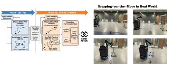
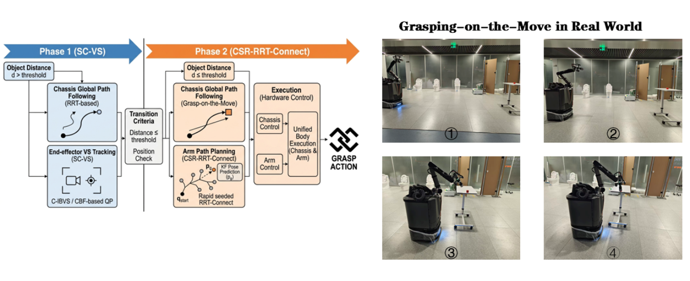
Graphical Abstract

1. Introduction

Mobile manipulators have the mobility of chassis movement and the operational flexibility of robotic arms, making them indispensable in scenarios such as intelligent manufacturing, logistics sorting, and home services [1]. Unlike traditional fixed-seat robotic arms, mobile manipulators have relatively flexible and unrestricted workspaces.
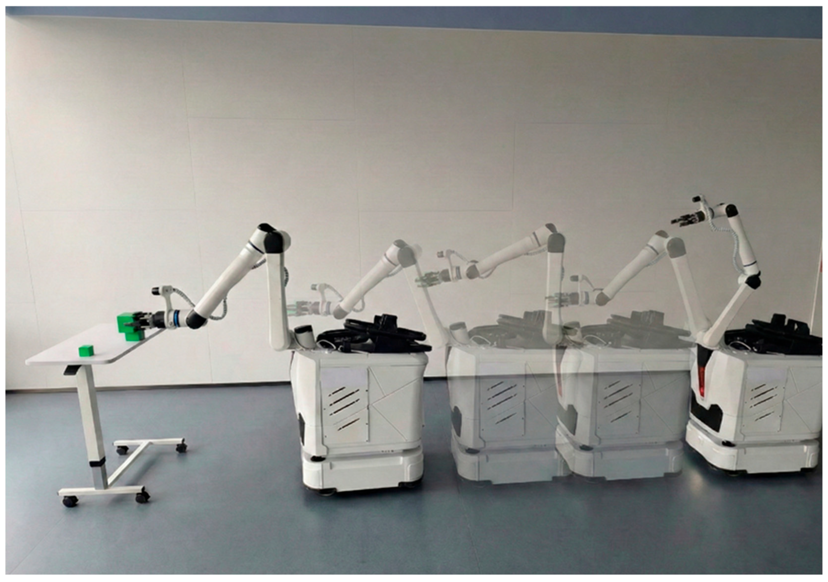
In actual task execution, due to the complexity of system control, composite robots typically still adopt a stop-then-grab control method; that is, the robotic arm performs the grasping action only after the chassis has moved to the designated position (as shown in Figure 1). This control method breaks down the overall operation of the composite robot into sub-tasks of “navigation to position—target perception—grasping execution.” When facing high-efficiency task requirements, the following problems exist:
(1)
Inefficiency due to motion redundancy: The composite robot is a nonlinear system as a whole, and the chassis and the robotic arm it carries have a high degree of coordination. However, the traditional control mode cannot fully utilize its operational freedom, resulting in low-motion capability and operational efficiency, and it cannot achieve continuous operation of “continuous simultaneous locomotion and manipulation”.
(2)
Dynamic Perception Deviation: When the robot moves continuously, the acceleration of the chassis and the inertia of the overall body cause vibrations to the vision sensors installed at the end of the robotic arm. This can cause the observed target to easily fall out of the field of view. This is because the chassis and the robotic arm are treated as two independent entities, unable to achieve feedback coordination. When the observed target is lost, the deviation caused by the chassis movement cannot be compensated for in time by the tracking motion of the robotic arm.
(3)
Lack of real-time capability: In dynamic scenarios involving motion grasping, the manipulator faces a strictly time-constrained execution period to grasp the target. Traditional path planning algorithms take too long to search for sampling points and generate paths within the full configuration space, making it impossible to generate a suitable path when the target enters the grasping range, which can lead to the target being missed or a collision.
To address these aforementioned problems, this paper proposes a two-stage collaborative motion planning method, which divides the overall motion of grasping into the following two stages:
Long-range target tracking stage: This stage employs a spatially constrained visual servo control method, which differs from typical image-error-dependent visual control methods. This paper combines chassis path prediction and trajectory points to constrain the robot arm’s motion. By using the pre-acquired chassis pose to constrain the robot arm’s motion and establish a search space during movement, this method ensures that the robot arm adjusts its posture in real time as it moves with the chassis to keep the target within visual range at all times, and also enables dynamic obstacle avoidance for the robot arm.
Close-range grasping phase: This phase involves rapid path planning based on sampling space constraints. For the brief grasping opportunities during motion grasping, this paper designs and proposes an improved rapid path planning method. This method compresses the search space by constraining the sampling space of path points to a subspace near the target. Experiments show that this method significantly improves the overall efficiency of path planning, ensuring accurate and stable target grasping by the robotic arm without chassis deceleration.
Based on the design improvements of the above algorithm, comparative experiments show that when the chassis maintains a movement speed of 0.3 m/s, the proposed method achieves a target grasping success rate of 92%, which significantly improves the robustness and efficiency of the composite robot in dynamic scenarios.

Related Work

The “Grasping-on-the-Move” task for mobile manipulators requires the robotic arm to coordinate tracking, approaching, and grasping the target while the chassis remains in continuous motion [2]. In this scenario, the system must maintain continuous chassis motion while executing the grasp, which requires highly reactive control strategies [3]. This involves a tight coupling of chassis–arm coordination, real-time perception, and dynamic path planning.
A.
Collaborative Motion Planning for Mobile Manipulators
Motion planning for mobile manipulators aims to coordinate the movements of high-degree-of-freedom arms and chassis. Existing approaches can be broadly categorized into decoupled planning and integrated planning [4].
Decoupled Planning: This method decomposes the problem into two sequential sub-tasks: chassis path planning and robotic arm grasping planning. This “Stop-and-Grasp” approach first plans the chassis path to the grasping “base,” then initiates the robotic arm’s grasping action only after the chassis has stabilized [5]. As noted in the introduction, while this simplifies control, its “wait-and-execute” pattern leads to inefficient task execution and demands stringent final positioning accuracy from the chassis, rendering it unsuitable for high-real-time scenarios.
Whole-Body Planning: This approach treats the mobile manipulator as a unified high-degree-of-freedom system, performing planning within a unified configuration space [6]. For instance, it simultaneously solves the motion of the chassis and manipulator by optimizing a unified objective function that incorporates task goals (e.g., end-effector position) and constraints (e.g., joint limitations and obstacle avoidance) [7,8,9]. While whole-body planning theoretically finds optimal solutions and avoids full-body collisions, its core challenge lies in high computational complexity [10]. For instance, while holistic optimization methods like Nonlinear Model Predictive Control (NMPC) provide optimal trajectories for rover and mobile manipulation systems, their receding-horizon optimization over the full state space typically incurs per-cycle costs incompatible with sub-150 ms grasping windows [11]. For “motion-based grasping” tasks requiring rapid response, this approach struggles to meet real-time requirements, and the complex optimization objective may lead to insufficient weighting of the core task of “tracking the target.”
B.
Visual Servoing and Target Tracking in Motion Grasping
Maintaining a “gaze” on the target during the base motion is a critical prerequisite for motion grasping. Visual servoing (VS) is a commonly used technique to achieve this objective [12].
Traditional visual servoing methods [13] are predominantly applied to fixed-base robotic arms or assume the base remains stationary. When applied to mobile manipulators, the base’s motion introduces significant disturbances to the visual servoing system. Prateek Arora & Christos Papachristos applied visual servoing principles to dynamic target grasping [14]; K. Jo and D. Chwa employed a mobile manipulator visual servoing approach for controlling omnidirectional mobile robots [15]. Both sought to leverage the chassis’s mobility to expand the working space of visual servoing; however, these methods are generally restricted to relatively slow chassis movements. In contrast to our proposed approach, existing vision-servo control methods for mobile manipulators [16] either sacrifice chassis maneuverability or fail to provide robust obstacle avoidance guarantees.
C.
Real-Time Path Planning for Dynamic Grasping
When the target enters the graspable range, the system must “immediately” plan a feasible grasping path. In “motion grasping” scenarios, this “grasping window” is extremely brief as the chassis remains in motion.
Sampling-based path planning algorithms (e.g., RRT, rapidly exploring random trees) and their variants (e.g., RRT* and RRT-Connect) [17,18,19] are commonly used tools for solving high-dimensional robotic arm planning. However, the standard RRT algorithm converges slowly when generating high-quality paths in complex spaces. To enhance real-time performance, researchers have proposed various improvements, such as Guided RRT (G-RRT) [20] or target-biased sampling [21]. Nevertheless, when confronting “on-the-fly” grasping opportunities, these methods remain inefficient due to their “blind” sampling across the entire configuration space, making it challenging to guarantee the discovery of a solution within the fleeting decision window [22].
In summary, existing research either employs an inefficient “decoupling” model or relies on computationally expensive “holistic” planning. In the more challenging “motion grasping,” a lightweight framework is still lacking that can simultaneously address (1) how the robotic arm can maintain robust and safe target tracking while the chassis executes a global path (including obstacle avoidance), and (2) how to achieve rapid grasping path planning within a short grasping window. This paper proposes corresponding solutions to these two challenges.

2. Materials and Methods

2.1. Motion-Based Grasping Framework

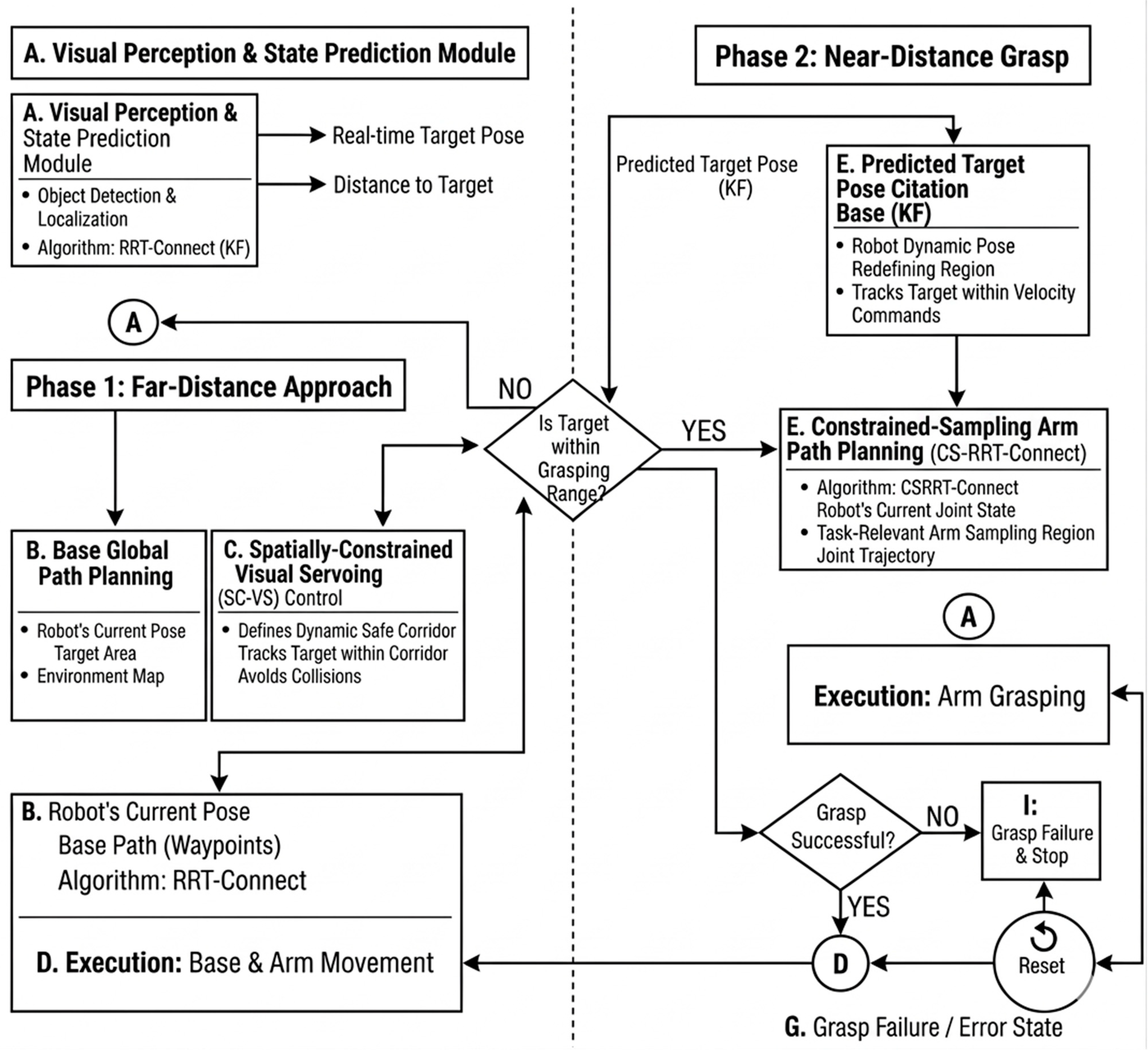
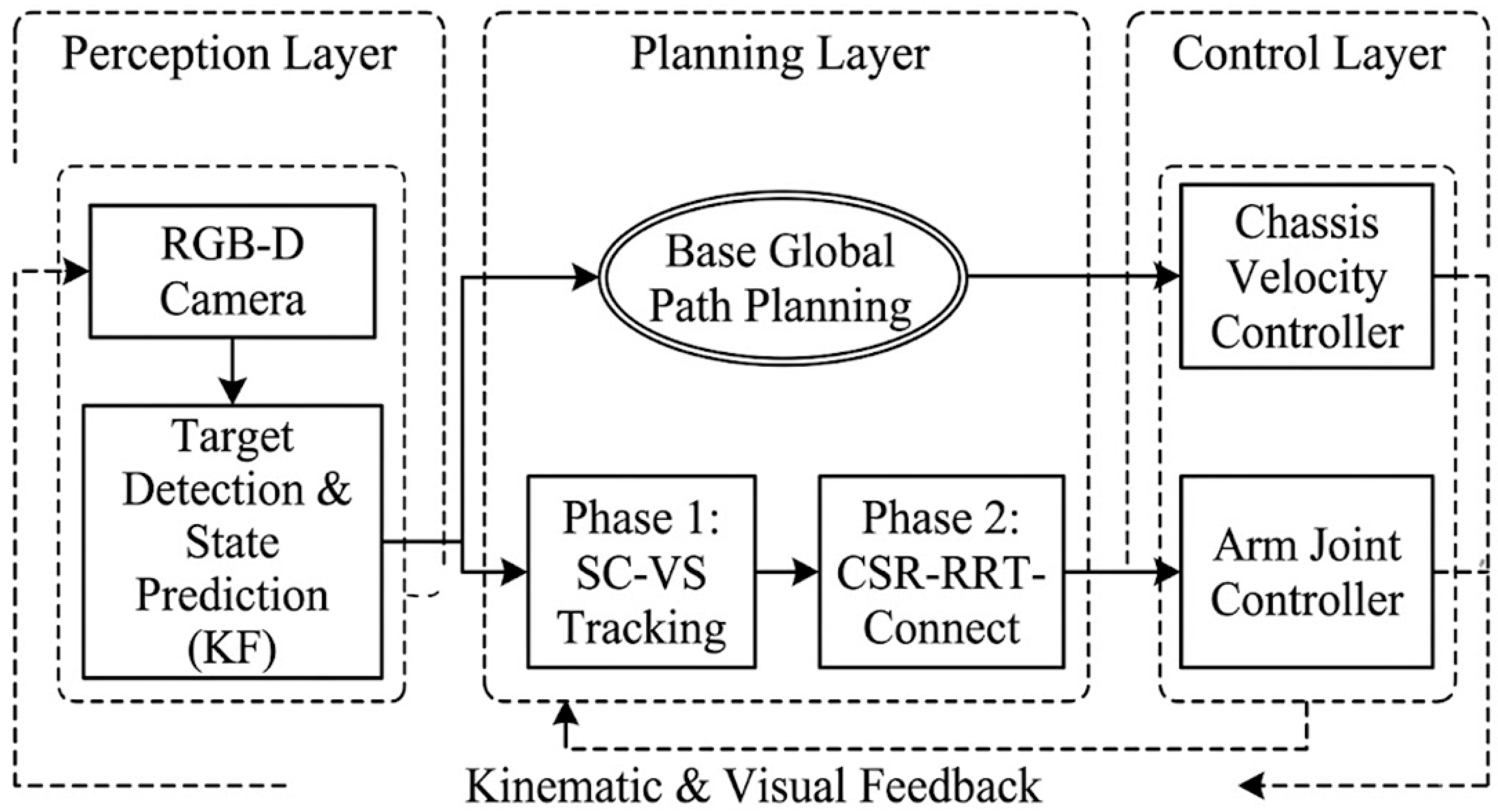
To enable efficient grasping by articulated robots during continuous motion, this paper proposes a two-stage closed-loop control framework (as shown in Figure 2).
The core design principle of this framework is to decouple the complex “motion-based grasping” task into two consecutive stages, accomplished through the coordinated operation of three major functional modules. In Stage 1 (long-range approach), the mobile manipulator begins at a distance from the target. The core tasks of this stage are as follows: The chassis plans a global path to approach the target, while the manipulator performs vision servo control to maintain robust tracking of the target and actively avoids obstacles. In Phase 2 (close-range grasping), the target enters the manipulator’s effective workspace. The core task here is to rapidly plan and execute a precise end-effector grasp while the chassis remains in motion. This framework comprises three modules—visual perception, spatial constraint servo, and path planning—the collaborative relationships and functions of which are detailed below.
A.
Visual Perception and State Prediction Module
This module provides real-time target information for decision-making and control. Its functions include real-time target detection and localization: the target’s 3D pose is acquired in the robot coordinate system via a depth camera. Phase-triggered grasping: the distance between the target and the robotic arm base is calculated in real time. When the target enters the predefined “graspable range,” it sends a trigger signal to the system, causing the framework to transition from Phase 1 to Phase 2. Kalman Filter (KF)-Based State Prediction [23]: In “motion grasping,” unavoidable system delays exist between perception, planning, and execution. To compensate for this delay, this module employs a Kalman Filter algorithm to model the dynamics of the target. In Phase 2, the module outputs not the target’s current position but the predicted grasping point at time T + ∆T, where ∆T represents the estimated planning and execution time. Specifically, the state vector is defined as x = [ x , y , z , v x , v y , v z ] T , employing a constant-velocity transition model. The measurement noise covariance R is initialized based on the nominal depth error specifications of the RealSense camera (approximately 1–2% at 1 m distance) and calibrated experimentally. The process noise covariance Q is configured by assuming bounded acceleration for the slowly moving target. This configuration effectively balances prediction smoothness with real-time responsiveness.
B.
Phase 1: Spatially Constrained Visual Servoing (SC-VS) Control Module
This module is pivotal for achieving robust target tracking and active obstacle avoidance, representing one of the core innovations of this paper. During Phase 1, chassis motion induces significant disturbances to the robotic arm’s visual servoing. While unconstrained visual servoing can maintain the target at the center of the field of view, it may induce “unsafe” robot poses. To address this, we propose a spatially constrained visual servoing (SC-VS) method. Its core idea is to dynamically construct a safety-constrained space using the chassis path planning results from Phase 1 (generated by RRT-Connect in Section 3.C). This module integrates the visual servoing objective function with this spatial constraint, ensuring that all joints and linkages of the robotic arm remain within a predefined “safety corridor” [24] while executing target tracking. This achieves active obstacle avoidance without compromising tracking performance.
C.
Path Planning Module
This module generates motion trajectories for the chassis and robotic arm, employing a two-stage design.
Stage 1: Chassis Global Path Planning
Upon initiation of Stage 1, the RRT-Connect algorithm plans a globally optimal (or suboptimal) path from the current position to the target area for the mobile chassis. This algorithm converges rapidly in high-dimensional spaces due to its bidirectional search capability. The generated waypoints serve not only for chassis navigation but are also passed to the SC-VS module in Section 3.B as the reference for generating the “safety corridor.”
Stage 2: Constraint-Sampled Manipulator Grasping Planning. This module is key to achieving rapid “on-the-fly” grasping and represents another core innovation of this paper. When Phase 2 is triggered, the system must complete high-dimensional path planning for the robotic arm within an extremely brief “grasping window.” Although robotic arm planning is also based on RRT-Connect, the standard algorithm’s “blind” sampling search in the global configuration space (C-space) is excessively time-consuming, making it difficult to meet the real-time requirements of motion grasping. To address this, we propose a Constrained-Sampling RRT-Connect algorithm (CS-RRT-Connect). This algorithm no longer uniformly samples the entire configuration space. Instead, it utilizes the target grasp pose predicted by the KF in Section 3.A to define a high-priority “task-relevant sampling region” (TRSR) within both the task space and configuration space. By concentrating the vast majority of sampling points within this region, CS-RRT-Connect significantly reduces the search time for effective paths and markedly improves planning efficiency. This ensures a high success rate for grasping even while the chassis continues to move.

2.2. Constrained-Image-Based Visual Servoing (C-IBVS)

Constrained-Image-Based Visual Servoing (C-IBVS). This method addresses how a mobile manipulator can robustly track targets while safely avoiding obstacles during the long-range approach phase of “motion-based grasping,” all while the chassis continues moving.
This method comprises three steps: (A) constructing a dynamic safety constraint space based on the chassis path; (B) performing target virtual plane mapping to enhance stability; and (C) designing a constrained IBVS control law to solve for coordinated motion.
A.
Establishing Chassis Paths and Dynamic Constraint Spaces
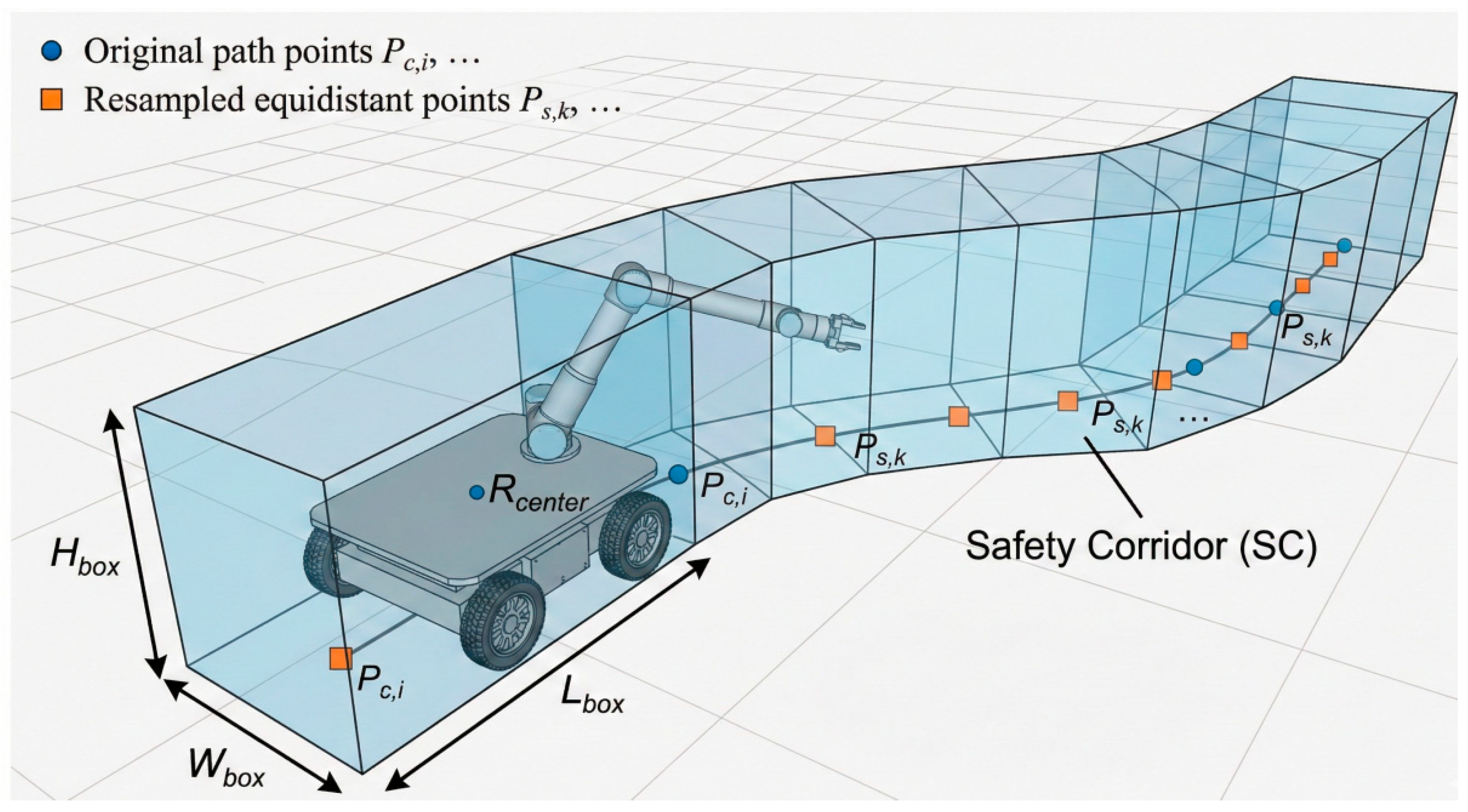
To ensure the robot arm’s motion aligns with the chassis’s global planning, we first utilized the chassis’s planned path to construct a dynamic “safety corridor.”
Chassis Path Planning: As previously mentioned, we employed the RRT-Connect algorithm to plan a chassis reference path P m = { p m , 1 , p m , 2 , …, p m , N } , where p m , i S E ( 2 ) represents the sequence of waypoints traversed by the chassis. We designated the center of the chassis’ upper surface as the reference point for p m to simplify subsequent calculations and prevent collisions between the robotic arm and the chassis itself.
Establishing the Constraint Space: We resampled Pm to obtain a set of equidistant spatial reference points S p = { s p , 1 , s p , 2 , …, s p , M } . Centered at each reference point s p , i , we constructed a three-dimensional bounding box B i . We defined the dimensions of this box as follows:
Horizontal Plane (X-Y Plane): Based on chassis dimensions s W b and L b , a safety margin of D_safe is added. The parameter D_{safe} (set to 0.1 m) defines the lateral safety clearance added to the chassis bounding box. This threshold ensures strict collision avoidance while preserving sufficient dexterous workspace for the robotic arm’s continuous operation:
W b o x = W b + 2 D s a f e
Height (Z-axis) is represented as H b o x = H m a x , where H m a x is the maximum working height of the robotic arm on the chassis base.
The union of all bounding boxes B i along the path forms a “safety corridor” C s a f e extending along the chassis path P m .
C s a f e = i = 1 M B i
Here, C s a f e represents the spatial constraints that the robotic arm must adhere to throughout the entire approach process. Any link A j of the robotic arm (at joint angle q ) must satisfy the following:
A j q C s a f e ,   j
B.
Virtual Plane Mapping for Target Points
Traditional IBVS (Image-Based Vision Servo) directly tracks features on the image plane. When the target is distant, minute image errors can cause the robotic arm to make large, unstable adjustments in three-dimensional space.
To address this issue, we employed “Virtual Plane” technology. Instead of tracking the image plane at Z = 0, we defined a fixed virtual plane P v in the camera coordinate system F c a m at Z = Z v , positioned closer to the robotic arm (Zv = 0.5 m).
According to the imaging principle of a camera, the relationship between the target point p = u , v T on the image plane and its mapped point P v = x v , y v , Z v T on the virtual plane P v is as follows:
P v = Z v · K 1 u v 1
where K is the camera intrinsic parameter matrix. Through this transformation, the control objective of IBVS shifts from tracking p to tracking p v . This reduces the control law’s sensitivity to depth estimation, resulting in smoother motion and effectively minimizing unnecessary adjustment amplitudes.
C.
Constrained-IBVS Control Law
The core of the C-IBVS control in this paper is solving an optimization problem with inequality constraints, which must simultaneously achieve two objectives:
Task Objective: Drive the feature point p v on the virtual plane to converge to the desired target point p v * .
Safety Constraint: Ensure the robot arm’s motion (joint velocities q ˙ ) always maintains the arm within the safe corridor C s a f e (defined in Section A).
We formulated this as a velocity-based Quadratic Programming (QP) problem [25], solved at each control cycle t :
m i n q ˙   1 2 J t a s k q q ˙ v d e s 2 +   1 2 λ d q ˙ 2
Task Objective Term Damping Term:
s · t ·   A s a f e q q ˙ b s a f e q
Safety Corridor Constraint:
q ˙ m i n q ˙ q ˙ m a x
Here, q ˙ is the joint velocity vector to be solved.
J t a s k is the Jacobian matrix of p v relative to q ˙ (including the image Jacobian and the robot Jacobian).
v d e s is the desired task space velocity used for error elimination.
λ d q ˙ 2 is a damping term employed to enhance solution uniqueness and stability.
The core of the safe corridor constraint is constructed based on the concept of the Control Barrier Function (CBF), where the A s a f e matrix and b s a f e vector jointly define the “safe feasible region” for q   ˙ (as shown in Figure 3).
The velocity-level QP is solved using the OSQP (Operator Splitting Quadratic Program) library. For our 6-DOF robotic arm, the QP problem consistently maintains a low-dimensional structure, consisting of n = 6 decision variables (joint velocities) and m = 25 inequality constraints (comprising joint position limits, velocity bounds, and the CBF-based safety corridor constraints). On the Jetson Orin NX platform, the average per-cycle solve time is strictly bounded within 5 ms, fully satisfying the real-time control requirements.

2.3. Real-Time Path Planning for Motion Grasping (CSR-RRT-Connect)

When the target enters the grasping range, the framework switches to Phase 2. For this phase, we propose a bidirectional fast exploration random tree connection algorithm (Constrained-Sampling-Range RRT-Connect and CSR-RRT-Connect) (C) that combines target position prediction (A) and constrained sampling (B).
A.
Target Position Prediction Based on Kalman Filter (KF)
In dynamic grasping tasks, planning a “currently” observed target position is ineffective for the following reasons. System Latency: There is an inherent delay T = t p + t e (as introduced in Section 2.1) from image acquisition (t0) to path planning completion (time t p ) and robotic arm execution (time t e ). Sensor Occlusion: If an “eye-in-hand” camera is used, the gripper may occlude the target in the final stage of the grasping action, resulting in loss of visual feedback.
To address this issue, we employed the Kalman Filter algorithm. This algorithm fuses visual perception information to estimate the relative motion state of the target. At the start of the grasping phase, we used Kalman filtering to predict the target state x p r e d at time t 0 + T , and assigned this predicted pose p g = x p r e d as the final goal point for path planning.
B.
Establishment of the Constrained Cylindrical Sampling Space
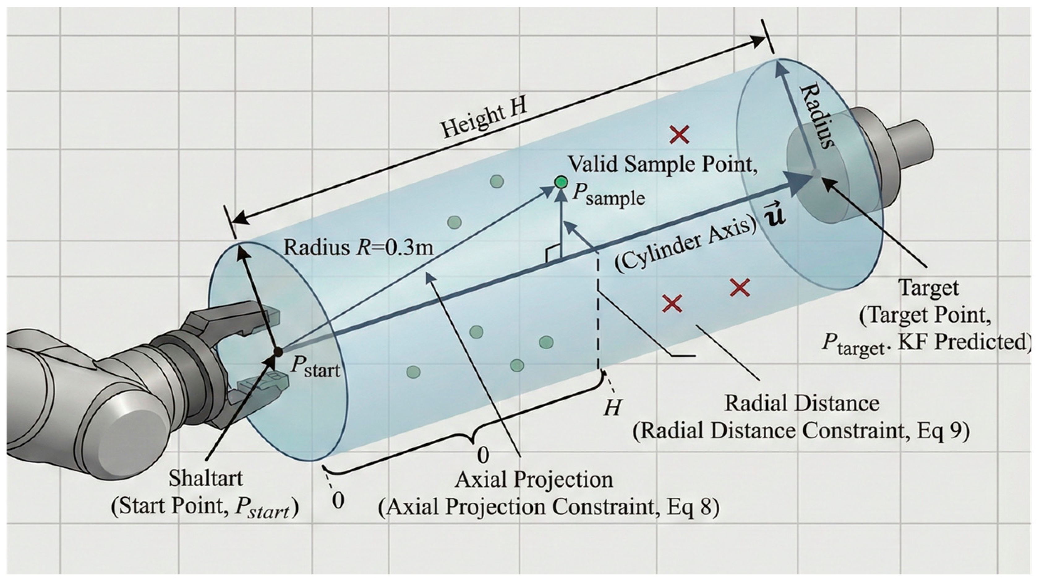
To improve sampling efficiency, we strictly limited sampling to a three-dimensional cylinder (task space) highly correlated with the task, denoted as C s a m p l e . We define this cylinder using the following elements (as shown in Figure 4). Starting point p s : Cartesian coordinates of the robotic arm end effector are defined at the current time t0. Target point p g : Coordinates of the future grasping point predicted by Kalman filtering in Section (A). Cylinder axis v a x i s : Vector pointing from the starting point to the target point, v a x i s = p g p s . Its unit vector is u ^   = v a x i s v a x i s . Cylinder height H: H = v a x i s . Cylinder radius R = 0.3 m. The cylinder radius is set to R = 0.3 m. We determined this value through preliminary sensitivity analysis: a smaller radius (e.g., R < 0.15 m) frequently over-constrained the arm, leading to planning failures by excluding feasible inverse kinematics solutions. Conversely, a larger radius (e.g., R > 0.45 m) increased the sampling space, deteriorating the planning time with diminishing returns. Thus, R = 0.3 m represents an optimal trade-off between spatial constraint efficiency and kinematic reachability.
Sampling point validity verification: To determine whether a random sampling point p r a n d is within C s a m p l e , two mathematical conditions must be met simultaneously: the axial projection constraint, where projection length t of p r a n d along the axis u ^ must be within the height range of the cylinder:
t = p r a n d p s u ^
where 0 ≤ t ≤ H.
Radial distance constraint: The perpendicular distance d from p r a n d to the central axis must be less than the radius R .
d = p r a n d p s t u ^
C.
CSR-RRT-Connect Path Planning Algorithm
Our CSR-RRT-Connect algorithm is an improvement on the standard RRT-Connect. Its core difference lies in the sampling strategy to ensure rapid convergence of the planning to the grasping task. The algorithm grows two trees bidirectionally in the configuration space (C-space): T s (starting from the current joint state q s ) and T g (starting from the target grasping posture q g , where q g is obtained by solving p g using IK). The algorithm’s iterative steps are as follows:
(1)
Constraint sampling: Instead of global sampling in the C-space, we directly generate a random point p r a n d within the task space cylinder C s a m p l e defined in section (B).
(2)
IK solution: Using the inverse kinematics (IK) solver, the joint coordinate q r a n d is found in the configuration space corresponding to p r a n d .
(3)
T s Extension: The node q n e a r that is closest to q r a n d is found in T s . Then, q n e a r is extended towards p r a n d by a step size ϵ to obtain q n e w .
(4)
Collision Detection: The path from q n e a r to q n e w is checked to ensure it is collision-free. If there is no collision, q n e w is added as a new node to Ts.
(5)
T g Connection: T s (the goal tree) attempts to connect to q n e w . The node q n e a r that is closest to q n e w is found in T g and attempts are made to extend from q n e a r to q n e w .
(6)
Path Generation: If the connection is successful (through collision detection), the two trees meet, and a valid path from q s to q g is found. The algorithm terminates and returns the path.
(7)
Iteration: If no connection is found, the roles of T s and T g are swapped, and steps 1–5 are repeated.
By strictly limiting sampling to C s a m p l e , CSR-RRT-Connect greatly reduces invalid exploration of irrelevant regions, significantly improving planning efficiency and meeting the stringent real-time requirements of motion grasping.

3. Results

In this section, we validate the effectiveness and robustness of the proposed two-stage collaborative grasping framework through a series of simulations and real-world experiments.
A.
System Control and Coordination Architecture
To realize the “Grasping-on-the-Move” action, tight coordination between the mobile base and the manipulator is required. Figure 5 illustrates the formalized closed-loop architecture, encompassing perception, planning, and control layers.
Furthermore, system latency is a critical factor for grasping dynamic targets. A delayed response can result in missed grasping windows as the base continuously moves forward. Table 1 presents the formalized timing and latency analysis of our system’s core control loop.
Timing Analysis: As detailed in Table 1, the total system latency from perception to control execution during the critical Phase 2 grasping stage is approximately 200 ms. Traditional high-dimensional RRT planners often require several seconds to find a valid arm trajectory, which completely violates the real-time requirements of a continuously moving chassis. However, our proposed framework overcomes this bottleneck. By utilizing the SC-VS to strictly constrain the spatial relationship and employing the CSR-RRT-Connect algorithm to restrict the sampling region to a predefined cylinder, the search space is drastically reduced. Consequently, the arm path planning time is compressed to approximately 150 ms. This high computational efficiency ensures that the mechanical execution is strictly synchronized with the dynamic grasping window, fully enabling robust “Grasping-on-the-Move” action.
B.
Simulation Experiments
Simulation Experiments and Ablation Research: The simulation platform is built based on ROS(Noetic) and CoppeliaSim(V4.1.0), with a Jetson Orin NX 16 GB (NVIDIA, Santa Clara, CA, USA) computing unit. The robot model consists of a two-wheeled differential chassis and a UR5 robotic arm.
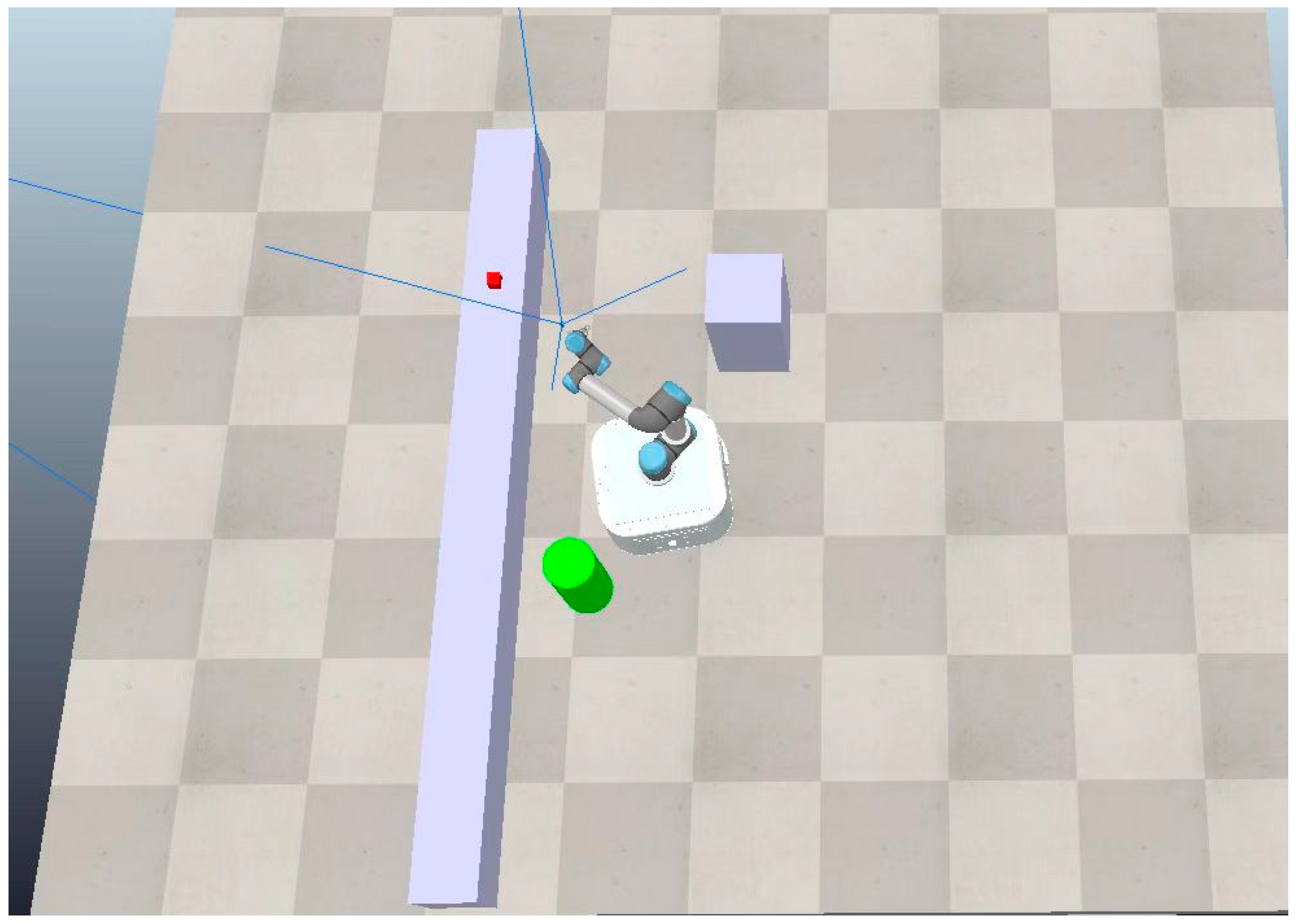
Experiment 1: Robustness of Target Tracking with SC-VS (C-IBVS) Experimental Design. To verify the tracking performance of the first stage alone, we set up an obstacle-populated environment (as shown in Figure 6). The mobile manipulator moves in circles around the target at different speeds (v = [0.2, 0.4, 0.6] m/s). We compared the two methods presented in this paper: “C-IBVS” (with spatial constraints) and “U-IBVS” (without constraints). The metric is the target tracking success rate (loss or collision during tracking is considered a failure).
Results of the Analysis: As shown in Table 2, Experiment 1 demonstrates that at high speeds, the U-IBVS experiences a dramatic increase in the range of motion of the robotic arm to keep the target centered in the field of vision, leading to frequent collisions with obstacles or loss of the target. The C-IBVS in this paper, through “safe corridor” constraints, consistently keeps the robotic arm within the safe range of the chassis, maintaining a tracking success rate of 98% or higher at all speeds, thus verifying its safety and robustness in dynamic motion.
Experiment 2: Path Planning Efficiency of CSR-RRT-Connect. Experimental Design: To separately verify the planning performance of the second stage, we compared our proposed “CSR-RRT-Connect” with the standard “RRT-Connect”. Both are fast planning algorithms for identifying feasible solutions. Metrics represent the average planning time ( T a v g ) and average path length ( L a v g ).
Results of the Analysis: As shown in Table 3, our CSR-RRT-Connect achieves a threefold reduction in average planning time ( T a v g ). This is because our constraint sampling strategy significantly reduces the invalid exploration of RRT-Connect in irrelevant regions. Standard RRT-Connect samples globally, and the first feasible path it finds is typically highly random and circuitous; by contrast, our CSR-RRT-Connect algorithm samples within a “cylinder,” which itself faces the target, thus finding statistically more “straight” feasible solutions with higher path quality.
C.
Real-World Experimental Platform Setup
After verifying the independent effectiveness of each module, we verified the performance of the integrated system on a real mobile manipulator platform. Hardware: The platform consists of a differential motion chassis and an RML-65 six-joint lightweight robotic arm. Perception and Computation: A RealSense depth camera (eye-in-hand) is integrated at the end flange. All computations are run onboard on a Jetson Orin NX 16 GB core development board.
Baseline Setup (Ablation Study of Baselines): To quantitatively evaluate the contributions of our two innovations (C-IBVS and CSR-RRT-Connect), we set up the following four algorithm configurations for comparison: B1 (U-IBVS + RRT-Connect): [Baseline 1] unconstrained tracking + standard planning; B2 (C-IBVS + RRT-Connect): [Baseline 2] improved tracking only + standard planning; B3 (U-IBVS + CSR-RRT-Connect): [Baseline 3] unconstrained tracking + improved planning only; and Ours (C-IBVS + CSR-RRT-Connect): [Our Method] Improved tracking + improved planning.
D.
Real-World Grasping Experiments
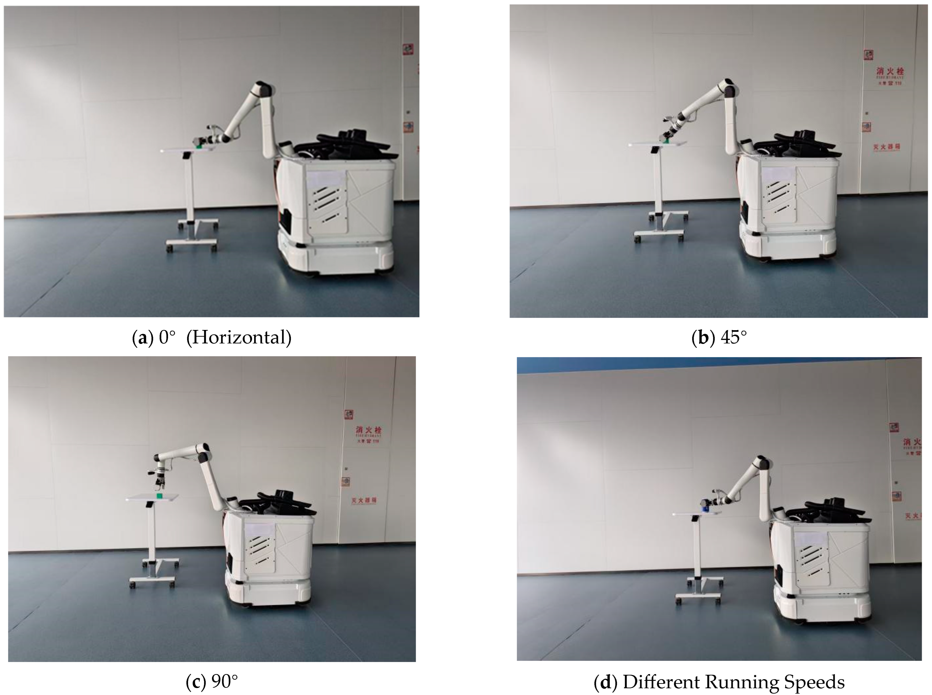
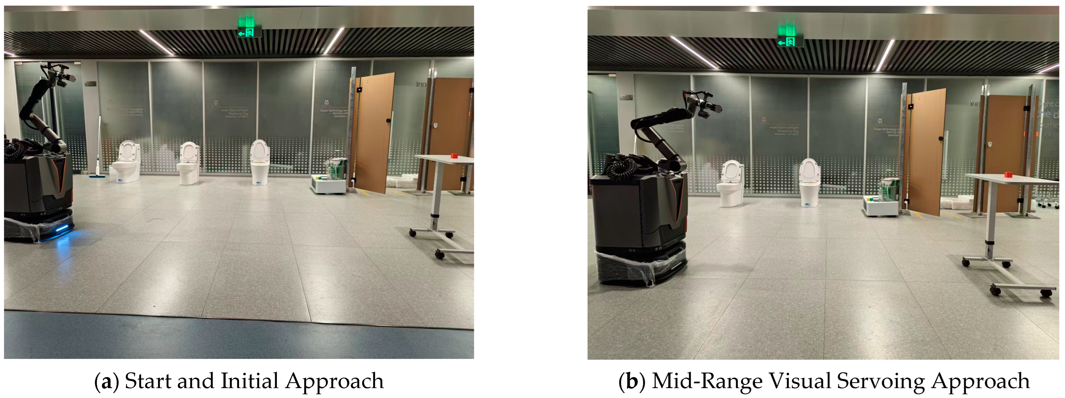
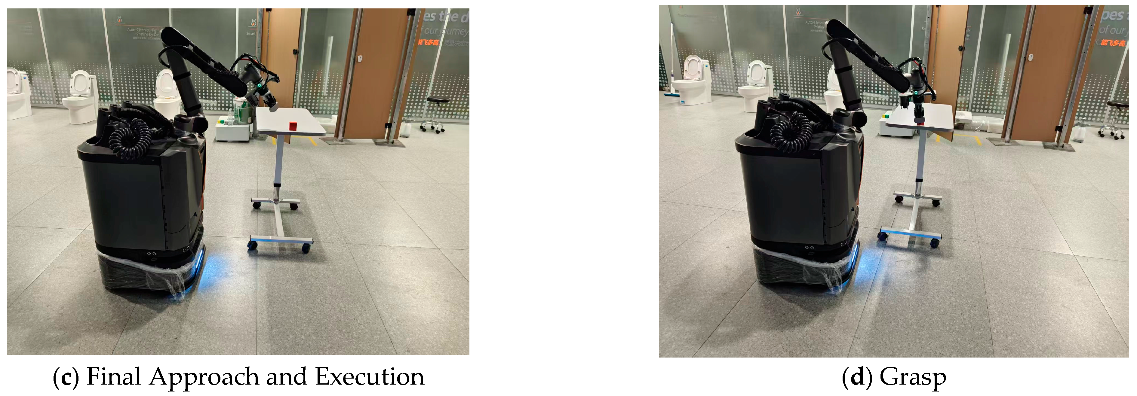
Experiment 1: Kinematic Robustness (Grasping with Different End-Effector Postures). Experimental Design: The robotic arm’s end-effector was required to perform grasping operations with postures of 0° (horizontal), 45°, and 90° (vertical). Each posture was repeated 50 times (as shown in Figure 7a–c).
Results Analysis: As shown in Table 4, the 90° posture (vertical grasping) was the most difficult for all methods. The success rate of the U-IBVS baselines (B1 and B3) dropped sharply in this position. The reason for this is that U-IBVS, in order to maintain tracking, may cause the “eye-in-hand” camera to tilt excessively, resulting in the loss of the target during the critical grasping phase. The C-IBVS methods (B2 and Ours) in this paper, through spatial constraints, can ensure that the camera maintains optimal observation even under constrained postures, with a success rate maintained above 90%, demonstrating the strong adaptability of C-IBVS to complex kinematic constraints.
Experiment 2: Dynamic Robustness (Grasping with Different Running Speeds). Experimental Design: The robot moved towards the target at a distance of 3 m and performed grasping operations at speeds of 0.1, 0.2, and 0.3 m/s, respectively. Each speed was cycled 50 times (as shown in Figure 7d). A visual sequence of the motion-grasping experimental execution in the real-word environment is shown in Figure 8.
Results Analysis: As shown in Table 5, this experiment clearly illustrates the robustness and generalization of our framework under varying operating conditions and dynamic disturbances. When the chassis speed increased to 0.3 m/s, it introduced significant dynamic disturbances, including tightened grasping windows and increased system vibrations. Under these challenging conditions, the success rate of the baselines (B1 and B2) using standard RRT-Connect dropped sharply, as their average planning time (shown in Table 2) exceeded the brief grasping window. In contrast, our proposed CSR-RRT-Connect (B3 and Ours), with its highly constrained search space and fast planning speed, effectively mitigated these dynamic disturbances. It maintained a remarkable 92% grasping success rate even at a high speed of 0.3 m/s, firmly demonstrating the system’s robustness against varying operational speeds and environmental dynamics.
Overall Conclusion: Experiment 2 proves that C-IBVS and CSR-RRT-Connect are indispensable for high-speed motion grasping, and our own method, included in this paper (Ours), which combines the two, was the only one that maintained high overall performance at any speed.

4. Discussion

4.1. Advantages of the Proposed Framework

Compared to traditional “Stop-and-Grasp” methods, our proposed two-phase collaborative framework (SC-VS and CSR-RRT-Connect) significantly improves operational efficiency. The experimental results demonstrate a 96% grasping success rate at a continuous chassis speed of 0.3 m/s, greatly outperforming the baseline methods (approx. 40%). By constructing a dynamic safety corridor and using Kalman Filter predictions to restrict the sampling region, the framework effectively resolves the high-dimensional planning time bottleneck and reduces perception deviations during movement.

4.2. Robustness and Generalization in Disturbance Scenarios

While the experimental results (Table 4) quantitatively demonstrate the system’s performance under varying base speeds, it is essential to discuss the framework’s inherent robustness against broader disturbance scenarios in real-world applications. During “Grasping-on-the-Move” actions, the inherent vibrations of the mobile base and visual latency introduce significant sensor noise and perception disturbances. Our framework is highly generalized to resist these issues. First, by incorporating the Kalman Filter for state prediction, the system effectively smooths out visual perception noise caused by chassis vibrations. Second, the proposed SC-VS establishes a dynamic safety corridor that loosely couples the arm and the base. Even if the base experiences unexpected positional disturbances or path deviations, the SC-VS ensures collision-free tracking within the predefined constrained space. Consequently, this two-phase architecture significantly enhances the system’s adaptability and robustness across diverse, dynamic environments beyond the current experimental setup.

4.3. Limitations and Challenges in Physical Deployment

Despite the high success rate at nominal speeds, deploying the “Grasping-on-the-Move” strategy on a physical robotic platform revealed several boundary limitations and system-level challenges:
Visual-Perceptual Constraints at High Speeds: When the chassis speed exceeds the nominal threshold, severe motion blur and image drift occur in the camera feed. This degradation in visual quality compromises the accuracy of the SC-VS tracking phase, making it difficult to lock onto the target in a stable manner.
Systematic Latency and Actuator Limitations: A critical challenge in physical deployment is the hardware–software synchronization lag. Although the central computer can rapidly compute and predict the accurate target state, communication delays and the mechanical response time of the end-effector pose constraints. Specifically, when the robotic arm reaches the pre-grasping pose, the relatively slow closing speed of the physical gripper compared to the chassis’ forward velocity can result in the target being accidentally pushed away rather than successfully grasped.
Dynamic Obstacle Avoidance and Base-Arm Synchronization: While the system handles static environments robustly, its real-time responsiveness to sudden dynamic obstacles is limited by current computational delays. Furthermore, under extreme temporal constraints, imperfect dynamic coupling and synchronization between the chassis and the arm can lead to the narrow, brief grasping opportunity being missed.

5. Conclusions

This paper addresses the inefficiency of the traditional “Stop-and-Grasp” mode in mobile manipulators by proposing an efficient and robust “Grasping-on-the-Move” cooperative planning framework. The core contribution of this framework lies in its two-stage design: In the long-range approach stage, a spatially constrained visual servoing (SC-VS) method is proposed. This method dynamically constructs a “safe corridor” using the chassis’ planned path, ensuring robust target tracking by the robotic arm while guaranteeing safe coordination between chassis movement and the robotic arm. In the short-range grasping stage, a constrained sampling CSR-RRT-Connect algorithm is proposed. This algorithm combines Kalman filtering (KF) for target state prediction and significantly reduces the sampling space of RRT-Connect, thus achieving rapid path planning within the short time window of “grasping.”
Multiple ablation experiments conducted on simulation and real physical platforms validate the effectiveness of this framework. Experimental results quantitatively demonstrate that SC-VS (C-IBVS) is crucial for the grasping success rate, especially in kinematically constrained postures, preventing target loss due to tracking. CSR-RRT-Connect is key to achieving grasping in high-speed motion, as it completes path planning in a shorter time compared to standard RRT-Connect, without missing the grasping opportunity.
To address these aforementioned limitations, our future work will focus on three aspects. First, we plan to integrate global-shutter or event-based cameras to eliminate motion blur during high-speed movement. Second, predictive delay compensation algorithms will be introduced to mitigate the communication and actuator latencies, ensuring that the gripper closes synchronously with the moving target. Finally, we will explore Model Predictive Control (MPC) combined with our RRT framework to enhance its real-time collision avoidance capabilities in highly dynamic and unpredictable environments.

Author Contributions

Conceptualization, Z.S., S.Z. and Q.J.; methodology, Z.S. and S.Z.; software, S.Z. and P.Z.; validation, P.Z., J.Y. and Z.S.; formal analysis, Z.S.; investigation, S.Z. and J.Y.; resources, Q.J.; data curation, P.Z. and J.Y.; writing—original draft preparation, Z.S.; writing—review and editing, Q.J. and S.Z.; visualization, Z.S. and P.Z.; supervision, Q.J.; project administration, Q.J.; funding acquisition, Q.J. All authors have read and agreed to the published version of the manuscript.

Funding

This research was funded by the Sichuan Provincial Engineering Technology Research Center for Prefabricated Cabin Power Equipment grant number SYTC2024001, and the Sichuan Province Central Guidance on Local Science and Technology Development Special Project grant number 2025ZYD0062. The APC was funded by Sichuan Provincial Engineering Technology Research Center for Prefabricated Cabin Power Equipment.

Institutional Review Board Statement

Not applicable.

Informed Consent Statement

Not applicable.

Data Availability Statement

The data presented in this study are available on request from the corresponding author. The data are not publicly available due to ongoing related research.

Conflicts of Interest

Author Jiping Yu was employed by the company Hangzhou Star Species Robotics Co., Ltd. The remaining authors declare that the research was conducted in the absence of any commercial or financial relationships that could be construed as a potential conflict of interest.

References

  1. Hvilshøj, M.; Bøgh, S.; Nielsen, O.S.; Madsen, O. Autonomous industrial mobile manipulation (aimm): Past, present and future. Ind. Robot 2012, 39, 120–135. [Google Scholar] [CrossRef]
  2. Zhang, X.; Zhu, Y.; Ding, Y.; Jiang, Y.; Zhu, Y.; Stone, P.; Zhang, S. Symbolic state space optimization for long horizon mobile manipulation planning. In Proceedings of the 2023 IEEE/RSJ International Conference on Intelligent Robots and Systems (IROS), Detroit, MI, USA, 1–5 October 2023; pp. 866–872. [Google Scholar] [CrossRef]
  3. Burgess-Limerick, B.; Haviland, J.; Lehnert, C.; Corke, P. Reactive Base Control for On-the-Move Mobile Manipulation in Dynamic Environments. IEEE Robot. Autom. Lett. 2024, 9, 2048–2055. [Google Scholar] [CrossRef]
  4. Thakar, S.; Rajendran, P.; Kabir, A.M.; Gupta, S.K. Manipulator Motion Planning for Part Pickup and Transport Operations From a Moving Base. IEEE Trans. Autom. Sci. Eng. 2022, 19, 191–206. [Google Scholar] [CrossRef]
  5. Chitta, S.; Jones, E.; Ciocarlie, M.; Hsiao, K. Mobile manipulation in unstructured environments: Perception, planning, and execution. IEEE Robot. Autom. Mag. 2012, 19, 58–71. [Google Scholar] [CrossRef]
  6. Wang, J.; Jin, Y.; Shi, J.; Li, D.; Sun, F.; Luo, D.; Fang, B. EHC-MM: Embodied Holistic Control for Mobile Manipulation. In Proceedings of the 2025 IEEE International Conference on Robotics and Automation (ICRA), Atlanta, GA, USA, 19–23 May 2025; pp. 13330–13336. [Google Scholar] [CrossRef]
  7. Haviland, J.; Sünderhauf, N.; Corke, P. A holistic approach to reactive mobile manipulation. IEEE Robot. Autom. Lett. 2022, 7, 3122–3129. [Google Scholar] [CrossRef]
  8. Minniti, M.V.; Farshidian, F.; Grandia, R.; Hutter, M. Whole-Body MPC for a Dynamically Stable Mobile Manipulator. IEEE Robot. Autom. Lett. 2019, 4, 3687–3694. [Google Scholar] [CrossRef]
  9. Sleiman, J.-P.; Farshidian, F.; Minniti, M.V.; Hutter, M. A Unified MPC Framework for Whole-Body Dynamic Locomotion and Manipulation. IEEE Robot. Autom. Lett. 2021, 6, 4688–4695. [Google Scholar] [CrossRef]
  10. Jin, T.; Zhu, H.; Zhu, J.; Zhu, S.; He, Z.; Zhang, S.; Song, W.; Gu, J. Whole-Body Inverse Kinematics and Operation-Oriented Motion Planning for Robot Mobile Manipulation. IEEE Trans. Ind. Inform. 2024, 20, 14239–14248. [Google Scholar] [CrossRef]
  11. Kalaycioglu, S.; Ruiter, A.D. Nonlinear Model Predictive Control of Rover Robotics System. Adv. Sci. Technol. Eng. Syst. J. 2023, 8, 44–56. [Google Scholar] [CrossRef]
  12. Giftthaler, M.; Farshidian, F.; Sandy, T.; Stadelmann, L.; Buchli, J. Efficient kinematic planning for mobile manipulators with non-holonomic constraints using optimal control. In Proceedings of the 2017 IEEE International Conference on Robotics and Automation (ICRA), Singapore, 29 May–3 June 2017; pp. 3411–3417. [Google Scholar] [CrossRef]
  13. Chaumette, F.; Hutchinson, S. Visual servo control. I. Basic approaches. IEEE Robot. Autom. Mag. 2006, 13, 82–90. [Google Scholar] [CrossRef]
  14. Arora, P.; Papachristos, C. Mobile Manipulator Robot Visual Servoing and Guidance for Dynamic Target Grasping. In Advances in Visual Computing. ISVC 2020; Bebis, G., Yin, Z., Kim, E., Bender, J., Subr, K., Kwon, B.C., Zhao, J., Kalkofen, D., Baciu, G., Eds.; Springer: Cham, Switzerland, 2020; p. 12510. [Google Scholar] [CrossRef]
  15. Jo, K.; Chwa, D. Robust Hybrid Visual Servoing of Omnidirectional Mobile Manipulator with Kinematic Uncertainties Using a Single Camera. IEEE Trans. Cybern. 2024, 54, 2824–2837. [Google Scholar] [CrossRef] [PubMed]
  16. Li, C.; Li, B.; Wang, R.; Zhang, X. A survey on visual servoing for wheeled mobile robots. Int. J. Intell. Robot. Appl. 2021, 5, 203–218. [Google Scholar] [CrossRef]
  17. LaValle, S.M. Rapidly-Exploring Random Trees: A New Tool for Path Planning; Technical Report TR 98-11; Computer Science Department, Iowa State University: Ames, IA, USA, 1998; Available online: https://api.semanticscholar.org/CorpusID:14744621 (accessed on 29 March 2026).
  18. Karaman, S.; Frazzoli, E. Sampling-based algorithms for optimal motion planning. Int. J. Robot. Res. 2011, 30, 846–881. [Google Scholar] [CrossRef]
  19. Kuffner, J.J.; LaValle, S.M. RRT-connect: An efficient approach to single-query path planning. In Proceedings of the 2000 IEEE International Conference on Robotics and Automation (ICRA), San Francisco, CA, USA, 24–28 April 2000; pp. 995–1001. [Google Scholar] [CrossRef]
  20. Ganesan, S.; Natarajan, S.K.; Thondiyath, A. G-RRT*: Goal-oriented sampling-based RRT* path planning Algorithm for mobile robot navigation with improved convergence rate. In Proceedings of the 2021 5th International Conference on Advances in Robotics, Kanpur, India, 30 June–4 July 2021; pp. 1–6. [Google Scholar] [CrossRef]
  21. Wang, X.; Ma, X.; Li, X.; Ma, X.; Li, C. Target-biased informed trees: Sampling-based method for optimal motion planning in complex environments. J. Comput. Des. Eng. 2022, 9, 755–771. [Google Scholar] [CrossRef]
  22. Yu, Q.; Zhou, J.; Xue, Z. Path planning of manipulator considering obstacle avoidance based on improved RRT algorithm. J. Braz. Soc. Mech. Sci. Eng. 2025, 47, 505. [Google Scholar] [CrossRef]
  23. Li, Q.; Li, R.; Ji, K.; Dai, W. Kalman Filter and Its Application. In Proceedings of the 2015 8th International Conference on Intelligent Networks and Intelligent Systems (ICINIS), Tianjin, China, 1–3 November 2015; pp. 74–77. [Google Scholar] [CrossRef]
  24. Toumieh, C.; Lambert, A. Decentralized Multi-Agent Planning Using Model Predictive Control and Time-Aware Safe Corridors. IEEE Robot. Autom. Lett. 2022, 7, 11110–11117. [Google Scholar] [CrossRef]
  25. Malmir, I. New pure multi-order fractional optimal control problems with constraints: QP and LP methods. ISA Trans. 2024, 153, 155–190. [Google Scholar] [CrossRef] [PubMed]
Figure 1. Stop-and-Grasp action.
Technologies 14 00210 g001
Figure 2. Motion-based grasping framework.
Technologies 14 00210 g002
Figure 3. Safe feasible region.
Technologies 14 00210 g003
Figure 4. Constrained cylindrical sampling space.
Technologies 14 00210 g004
Figure 5. Closed-loop control and coordination architecture between the mobile base and the manipulator.
Technologies 14 00210 g005
Figure 6. Simulation and experiment.
Technologies 14 00210 g006
Figure 7. Real-world grasping experiments.
Technologies 14 00210 g007
Figure 8. Visual sequence of motion-grasping experimental execution in a real-word environment.
Technologies 14 00210 g008aTechnologies 14 00210 g008b
Table 1. System timing and latency analysis for the control loop.
ModuleOperationAverage Latency/Frequency
PerceptionImage acquisition and target detection~33 ms (30 Hz)
PlanningSC-VS tracking computation~10 ms (100 Hz)
CSR-RRT-Connect path planning~150 ms
ControlBase and arm joint control command~10 ms (100 Hz)
SystemROS node communication delay~5 ms
Total execution loop latency (Phase 2)~198 ms
Table 2. Tracking success rate: circling the target at different chassis speeds (%).
0.2 m/s0.4 m/s0.6 m/s
U-IBVS96%92%88%
C-IBVS100%100%98%
Note: All percentage success rates are derived from 50 independent trials per condition. The standard deviation across all reported conditions is strictly within ±3%.
Table 3. Path planning efficiency of CSR-RRT-Connect.
Average   Planning   Time   ( T a v g / s ) Average   Path   Length   ( L a v g / m )
RRT-Connect0.431.68
CSR-RRT-Connect0.150.93
Table 4. Grasping with different end-effector postures.
45°90°
B190%80%68%
B294%92%86%
B392%88%82%
Ours98%96%92%
Note: All percentage success rates are derived from 50 independent trials per condition. The standard deviation across all reported conditions is strictly within ±3%.
Table 5. Dynamic robustness (grasping with different running speeds).
0.1 m/s0.2 m/s0.3 m/s
B186%62%46%
B288%66%50%
B396%92%88%
Ours98%96%92%
Note: All percentage success rates are derived from 50 independent trials per condition. The standard deviation across all reported conditions is strictly within ±3%.
Disclaimer/Publisher’s Note: The statements, opinions and data contained in all publications are solely those of the individual author(s) and contributor(s) and not of MDPI and/or the editor(s). MDPI and/or the editor(s) disclaim responsibility for any injury to people or property resulting from any ideas, methods, instructions or products referred to in the content.