1. Introduction
1.1. General Context and Motivation
Over the past few decades, energy consumption and pollution have increased significantly. Approximately 30% of greenhouse gas emissions are due to the transport sector, underscoring an urgent intervention is needed for efficient reductions [
1]. The growing number of travelers led to the continuous development of public transportation systems, particularly trains. The latter is increasingly preferred over other transport modes due to its ability to carry large numbers of passengers. Although railway electrification is considered a promising solution, it still depends on carbon-intensive electricity grids [
2]. The advancement in rail transport enables fast travel, however inducing environmental concerns, such as CO
2 emissions and climate change, evoking the need to enhance energy regulation and performance within railway systems [
3]. Railways, representing a major element of transport infrastructure, require significant energy quantities, rendering the search for sustainable energy solutions crucial [
4].
To further decarbonize railways, the integration of renewable energies and storage systems into the railway traction network has therefore become essential to ensure a sustainable energy transition [
5]. Among these, solar energy is of great interest, attributed to its evolution and reduced costs [
6]. Furthermore, wind energy is widely investigated as a reliable energy source, particularly in high wind potential regions [
7]. The role of RES in enhancing solar power performances is discussed in [
7]. However, some challenges should be overcome when renewable energies are fully integrated into railway systems. The random nature of RESs, such as solar and wind energy, necessitates the development of more reliable energy storage systems [
8].
1.2. Literature Review
Much research has looked into how RES could be used in train systems. Some have looked at how well RES-powered traction networks perform [
9,
10], while others have looked at specific problems such as train safety [
11], changes in energy supply [
12], hybrid traction supply systems [
13], and solar integration at the substation level [
14]. Researchers have also looked into problems with power quality and how to coordinate train timetables using RES [
15,
16].
Energy storage systems are designed to accumulate surplus power produced by renewable sources in DC microgrid stations and provide it when there is a generating shortage. In this way, energy storage systems maintain both voltage stability and power balance within DC microgrid stations, addressing the intermittent nature of renewable production and fluctuations in load demand [
17,
18,
19]. Due to their technological maturity and lower cost compared to other energy storage solutions, batteries are widely used in various applications, particularly in DC microgrids [
20,
21]. However, batteries have low power density, resulting in slower dynamic responses. Consequently, batteries alone may not provide sufficient auxiliary services to DC microgrids during sudden variations in load demand or RES generation, potentially leading to power outages during severe transients. Supercapacitors, known for their high-power density and fast dynamic support, can compensate for the slow response of batteries.
Nevertheless, SCs are more expensive than batteries, so reaching a compromise between performance and price is essential. This compromise can be achieved effectively by combining BTs and SCs to form an HESS. The latter has been widely adopted in most hybrid energy storage developments, as the two components complement their respective limits while maintaining relatively low overall costs [
22]. SCs are ideal for handling rapid energy spikes, while batteries are more suited for the storage of large quantities of energy over time [
23]. The integration of HESS in microgrid stations presents significant challenges.
Dynamic stress on batteries during sudden environment changes can be reduced by implementing an HESS [
24,
25]. Even though earlier studies have demonstrated improved dynamic performance with HESS integration, little is known about how SC and BES interact. Moreover, the effective use of ESS in DC microgrids is restricted by the lack of optimized energy management strategies in many current HESS implementations.
An energy management strategy (EMS) is necessary for HESS in DC microgrid stations in order to effectively coordinate the BTs and SCs’ charging and discharging process and ensure power balance and voltage stability. It dynamically adjusts the power flow from BTs and SCs in response to varying conditions such as solar irradiance, wind speed, and load demand, thereby optimizing system performance and reliability.
In order to control power exchange between the DC bus and HESS, a variety of energy management techniques have been proposed in the literature [
26,
27,
28,
29,
30,
31]. These approaches are generally classified into three main categories: filter-based control (FBC), droop-based control (DBC), and rule-based control (RBC). A key limitation of these controllers lies in their sensitivity to changes in system parameters. Therefore, an accurate mathematical model of the system is required for its successful implementation. The RBC is known for its simplicity and ease of implementation, making it a popular choice for real-time energy management applications [
32]. However, RBC is sensitive to parameter variations, which can be a disadvantage. The DBC methods have been demonstrated to be among the most efficacious decentralized control methods [
33]. In [
34], the authors provided a thorough analysis and comparison of the various droop control strategies used in microgrid systems. It is important to remember that HESS cannot be directly managed using conventional droop control techniques. FBC uses a filter to decompose the electricity into high- and low-frequency components. This method is characterized by its cost-effectiveness and ease of use. However, the main drawback of FBC is its failure to account for the state of charge of storage devices [
35].
Intelligent control strategies, such as fuzzy logic control (FLC), artificial neural networks (ANNs), and evolutionary algorithms (EAs) like genetic algorithms and dynamic programming, offer reliable and efficient alternatives. FLC, in particular, has proven to be both simple and effective for managing complex systems without requiring precise mathematical models. According to [
36,
37,
38,
39,
40], FLC has been applied in HESS control. In [
37], a three-mode FLC strategy for HESS power allocation is proposed. One mode focuses on energy exchange between the SC and BT in a photovoltaic-integrated HESS, allowing imbalances between supply and demand to be compensated via a multi-mode distributor based on FLC. The goal is to prevent overcharging or deep discharging of storage devices. The implementation study demonstrated acceptable SOC ranges for the storage systems and improved power compensation efficiency.
In [
38], energy-saving methods for hydrogen hybrid systems on small vessels are examined by comparing various energy management approaches to reduce energy consumption. In [
39], a fuzzy logic control algorithm is used to efficiently operate an HESS composed of BTs and SCs. A fuzzy logic-based hybrid storage method combining BTs and SCs for the safe and effective operation of a regenerative braking system is presented in [
40]. The authors of [
41] further enhanced FLC performance by optimizing membership functions using a particle swarm optimization (PSO) algorithm, which increases the complexity of the management algorithm.
Table 1 presents a comparative review of the most prominent EMS techniques. It highlights their key contributions, advantages, and limitations. For more details, the interested readers are referred to [
34].
1.3. Contributions and Scope
Railway systems utilizing renewable energy sources demonstrate significant variability in their power profiles, primarily attributed to unpredictable weather conditions and the periods of train arrivals and departures. In this dynamic and unpredictable environment, fuzzy logic control emerges as an efficient option due to its capacity to handle nonlinearities and uncertainties without requiring an exact mathematical description of the system.
The studied system consists of a stationary hybrid RES (photovoltaic/wind) associated with a hybrid energy storage system (batteries and supercapacitors) located at the station; energy conversion is achieved using DC/DC and AC/DC converters. The trains represent the mobile system, equipped with supercapacitors allowing the fast charging and engines.
In this paper, a new energy management strategy based on fuzzy logic (F-EMS) is proposed, specifically designed to handle the nonlinear and uncertain behaviors associated with renewable energy sources. By combining the advantages of fuzzy logic with the use of a low-pass filter, this method directs rapid power fluctuations toward the supercapacitors. It thus enables dynamic balancing of the energy flow within the HESS, while respecting the charging constraints of both batteries and supercapacitors, and maintaining a stable DC bus voltage.
By contrast, classical energy management techniques such as RBC, DBC, and FBC exhibit a great deal of rigidity. Their usefulness in railway applications integrating renewable energy sources is limited by their general sensitivity to system parameter variations and lack of adaptability to changing or disturbed conditions. Furthermore, although artificial intelligence-based methods (ANNs, and EAs) perform well in terms of adaptation and optimization, they frequently require large amounts of training data and significant processing capacity. These limitations make it difficult to deploy them in real time, especially in decentralized or embedded systems like those found in smart rail networks. F-EMS is therefore a valuable trade-off between robustness, performance, and complexity—particularly well-suited for rail microgrid energy management.
The main contributions of this study are as follows:
The novelty of this article concerns the fuzzy logic-based EMS (F-EMS) proposed for a railway system integrating RES and HESS.
The study introduces a new F-EMS strategy for DC bus voltage control in a microgrid station under varying irradiance and wind conditions.
The fuzzy logic controller, associated with a low-pass filter, is utilized for storage device energy management, taking into account the constraints imposed by BTs and SCs, charging within acceptable limits.
The proposed F-EMS performance is tested and validated under variable irradiance and wind speeds for three stations (A, B, and C) where trains are equipped with onboard SCs for rapid charging during stops.
Maximum power point tracking (MPPT) algorithms are implemented for photovoltaic and wind power optimization.
This study illustrates the simplicity and robustness of F-EMS and demonstrates the potential of intelligent fuzzy logic techniques for energy management, opening up new avenues for traction system research.
The paper is structured as follows:
Section 2 presents the studied railway system.
Section 3 provides the modeling of renewable energy sources.
Section 4 deals with the modeling of energy storage systems.
Section 5 introduces the proposed F-EMS. Simulation results, obtained using the MATLAB/Simulink environment, are illustrated in
Section 6. Finally, the study is concluded in
Section 7, where we provide a conclusion and illustrate the opportunities for future research.
2. Studied Railway System
Figure 1 represents the railway system under study. It comprises three passenger stations (A, B, and C) separated by 10 km and 12 km apart, respectively. Trains stop at each station for 5 to 10 min. Train 1, operating on the left-hand track, proceeds from Station A to Station C, whereas train 2, running on the right-hand track, terminates its trip at Station A. The structure and components of the stations are similar.
Each station is powered by two renewable energy sources, including a photovoltaic generator and a wind turbine system. The maximum power extraction from both sources is achieved using the MPPT algorithm. The energy produced by the PV/Wind sources is stored in a hybrid energy storage system comprising batteries and supercapacitors. The mobile element of the railway system is the train. It is equipped with supercapacitors that function during braking and acceleration phases. The SCs are the most appropriate storage devices for the railway system due to their rapid charge and discharge capabilities. Additionally, the train is equipped with electric motors and a pantograph mounted on the roof, which is raised when the train is stationary and lowered while in motion between stations.
For simplification, the other components of the train and its operation are not considered in this work. Moreover, the rail system’s investment costs are not considered. The proposed F-EMS is introduced to optimize the power flow between RES, HESS, and the trains. When the train is at a station (charging mode), the SCs are charged using energy from the station’s HESS. While the train is moving between stations (discharging mode), the SCs supply the energy required by the train.
These microgrids can provide dependable, quick, and sustainable EV charging since they may combine RES and HESS. Adoption of comparable intelligently controlled microgrids for EV parking lots, such [
43,
44], has shown a great deal of promise in lowering grid reliance and converting such stations into active nodes of future smart transportation networks.
DC Microgrid Station Configuration
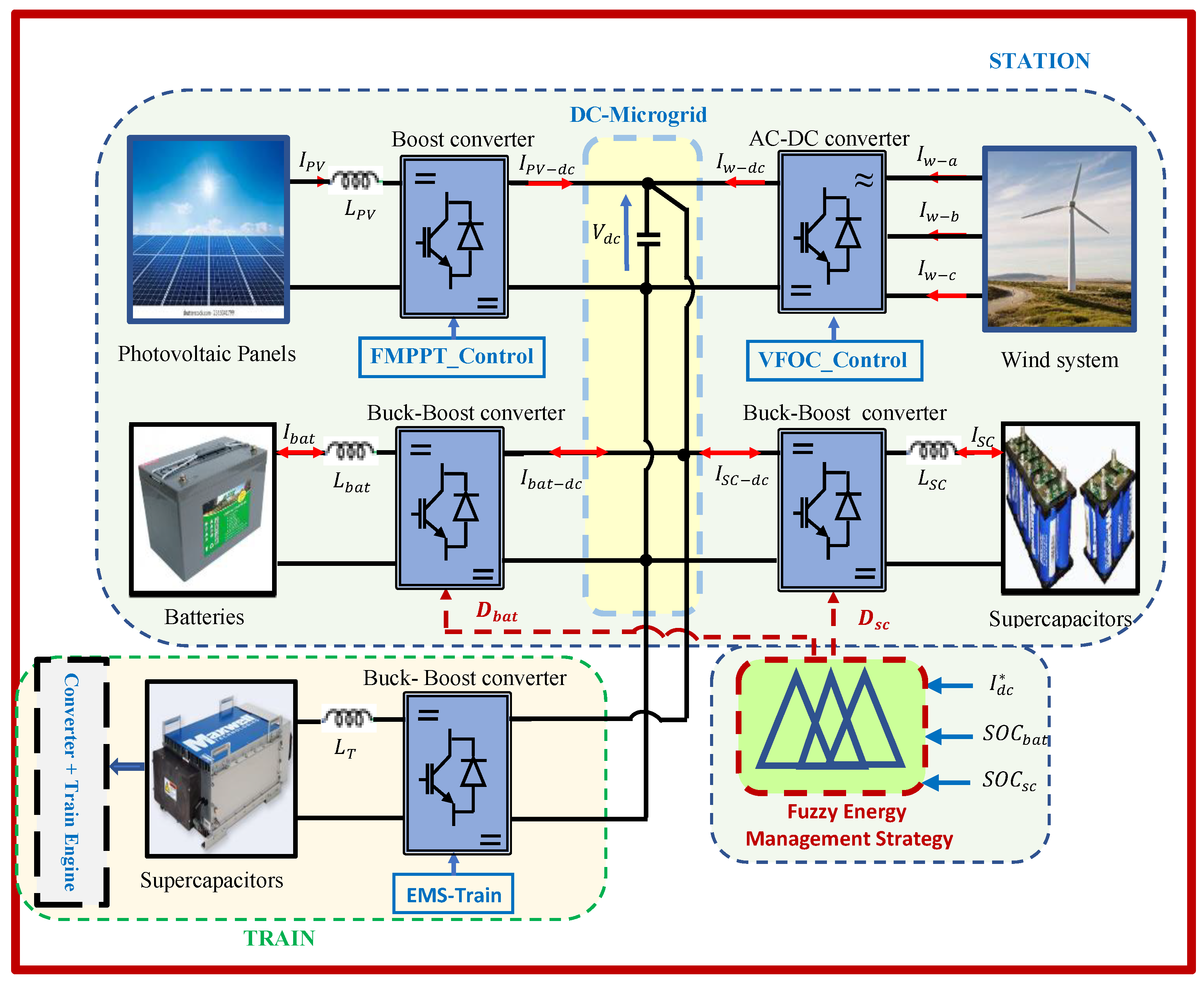
Each station represents a microgrid that combines photovoltaic, wind power systems, and hybrid storage elements, as represented in
Figure 2. The overall hybrid system is designed to operate autonomously, ensuring a reliable and sustainable energy supply. Power electronic converters are used to transform electrical energy. The photovoltaic panels are connected to the microgrid via a boost converter, managed by a fuzzy MPPT controller to achieve optimal PV power extraction.
The wind energy system includes a horizontal-axis wind turbine and permanent magnet synchronous generator. It is interfaced with the microgrid through an AC/DC converter controlled by a field-oriented control (FOC) strategy.
The power flow from the DC bus and HESS (BTs and SCs) is controlled by bidirectional buck-boost converters, allowing independent control of each storage device. Using the DC/DC buck-boost converters’ control, the balanced power is kept stable and the DC bus voltage is maintained at 750 V. Once the train is in station, the SCs are charged from the HESS through a buck-boost converter. The F-EMS is designed to supervise the railway system and improved its energy efficiency by optimizing resources usage during train stops. Additionally, it facilitates the rapid and efficient recharging of supercapacitors at each station.
3. Modeling of Renewable Energy Resources and HESS
3.1. Photovoltaic Model
Photovoltaic cells convert sunlight directly into electrical power. The generated power depends on environmental factors such as solar irradiance and temperature [
42].
where
G and
T are the solar irradiation and ambient temperature, respectively. The PV electrical current is expressed as follows [
45]:
where
and
are the photocurrent and saturation current, respectively.
denotes the shunt resistance, and
represents the serial resistance of the PV panel.
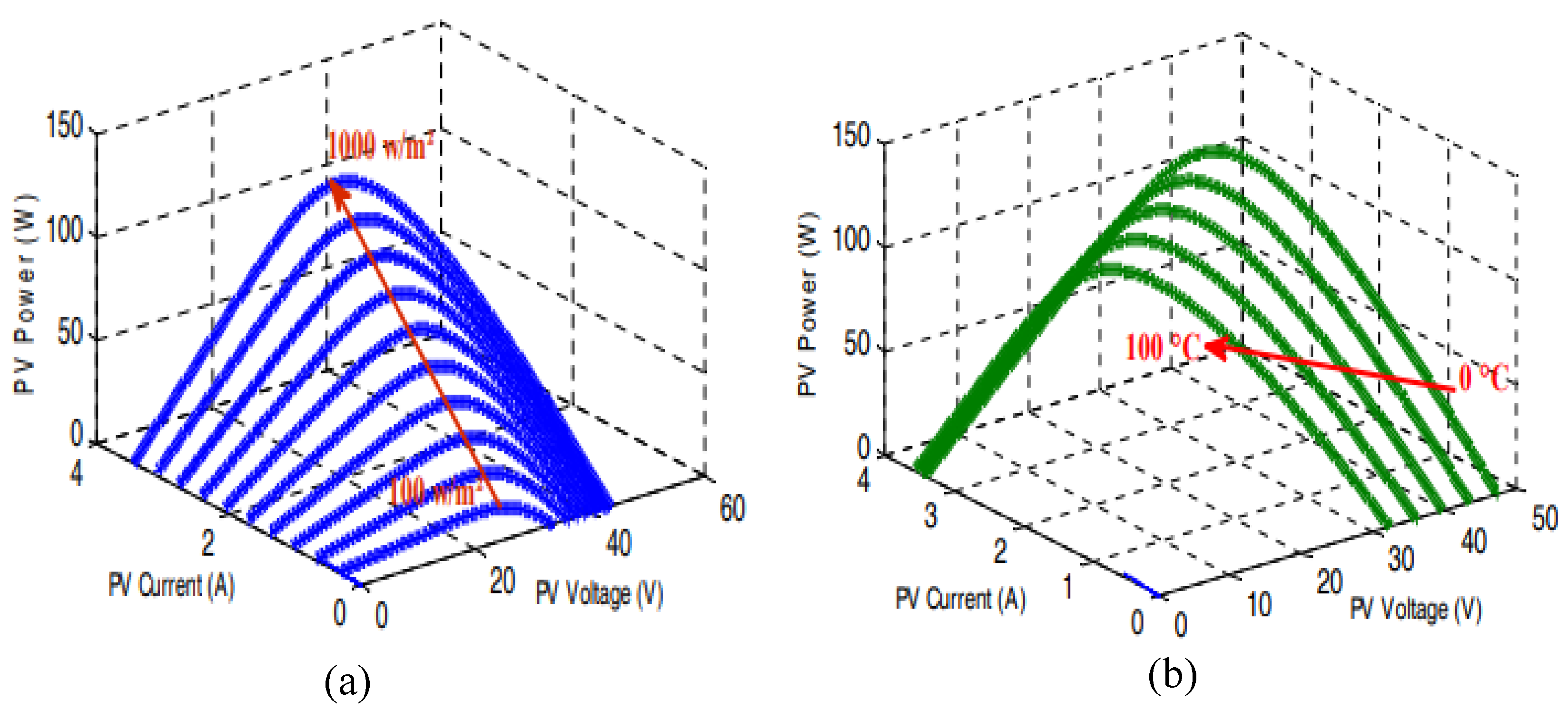
In this work, SIEMENS SM 110 modules [
46] are used. The PV panel characteristics are shown in
Figure 3 under various irradiance levels at a fixed temperature of 25 °C and under various temperatures with a constant irradiance of 1000 W/m
2.
These characteristics highlight the nonlinear nature of the photovoltaic panel. To ensure continuous operation at the maximum power point, a fuzzy logic-based MPPT algorithm is integrated into the system [
47].
3.2. Wind Turbine Model
Wind turbines transform the kinetic energy of flowing air into electrical power. Various theoretical and mathematical models have been proposed to represent the basic principles of wind turbine functioning [
48]. The wind-derived power can be expressed as follows [
49,
50]:
The torque generated by the turbine is given by
where
- -
is the swept area of the wind turbine;
- -
is the air density, and is the wind velocity;
- -
is the wind turbine speed, and G is the mechanical gearbox ratio.
Figure 4 shows the wind turbine’s operating zones. In the second zone, the system operates in MPPT mode to extract the maximum available wind power. When the wind speed rises above the nominal value, the wind power is adjusted to its rated value by varying the pitch angle
(zone III). In contrast, the turbine remains inactive in Zones I and IV due to wind speeds falling outside the operational limits [
51].
PMSG Model
Permanent magnetic synchronous generators (PMSGs) are frequently utilized for wind energy conversion owing to their high efficiency and dependability. Their functioning is based on electromagnetic induction and the magnetic properties of permanent magnets, which are founded on basic physical principles. In the dqdq reference frame, the PMSG’s electrical model in matrix form and the formula for electromagnetic torque are as follows [
52]:
with
and
representing the d–q axis voltages,
and
denoting the d–q axis currents,
and
standing for the d–q axis inductances,
being the stator phase resistance, and
representing the magnet flux linkage.
Field-oriented control is used to control the PMSG. This approach controls the generator’s rotational speed and stator current, as described in reference [
53].
4. Energy Storage Devices’ Modeling
4.1. Battery Modeling
Batteries are connected to the DC microgrid via a bidirectional buck-boost converter. Numerous models have been developed in the literature to describe battery behavior [
28,
30,
49,
50]. A commonly used model, characterized by high energy density, is proposed in [
54,
55]. In this study, the RC model is adopted. An equivalent circuit model for battery is shown in
Figure 5.
The battery voltage is expressed by the following equation:
The battery state of charge can be calculated as follows:
where
denotes the nominal capacity (Ah),
represents the electromotive force corresponding to the no-load voltage, and
denotes the internal resistance. Meanwhile,
represents the current flowing through the battery,
denotes the capacitor voltage of the battery, while
represents the initial amount of electric charge.
4.2. Supercapacitor Modeling
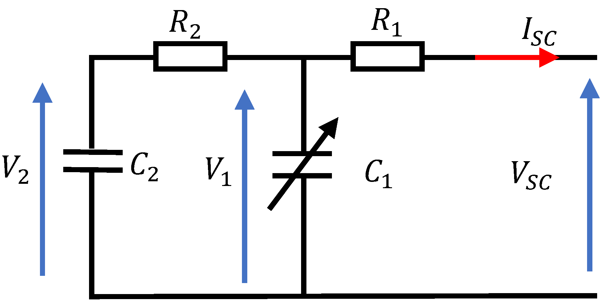
Due to the battery’s slower dynamic response and the potential of early deterioration, a secondary energy storage device is used. Supercapacitor technology is selected for its high-power capability. It is connected to the microgrid via a bidirectional buck-boost converter and is designed to absorb or supply power peaks.
Figure 6 gives the simplified circuit model. The first R
1C
1 represents the fast-response behavior of the supercapacitor during rapid charge/discharge cycles over a few seconds. The R
2C
2 branch models the slower dynamics, capturing the internal energy redistribution that occurs over a span of several minutes. This branch complements the first, providing a more complete representation of the supercapacitor’s behavior.
The primary capacitance C
1, referred to the differential capacitance, depends on the voltage V
1, a constant capacitance C
0, and a parameter C
v; it can be calculated as follows [
56]:
The supercapacitor voltage is given by the following equation:
The charge
is calculated using the follow equation:
5. Proposed Fuzzy Energy Management Strategy
The design and implementation of an appropriate management system is very important in a hybrid energy systems, as well as the selection of an optimal control method for HESS application and system configuration. A prudent power strategy is necessary to guarantee the safe, steady, and system-effective operation.
5.1. Station DC Bus Control
In remote areas, renewable energy systems frequently employ a shared DC bus for several reasons such as simplicity, flexibility, and compatibility with multiple energy sources. However, one of the main challenges is the precise and prompt DC bus voltage regulation. HESS is utilized to swiftly restore the DC bus voltage and efficiently allocate energy between the storage system devices (SCs, BTs) in an autonomous system.
Figure 7 shows the DC bus voltage control at its specified reference value (
V); a proportional integral (PI) corrector is used to compute the reference current.
The EMS provides the reference currents for both the batteries and the supercapacitors. In the event of a malfunction in an element such as SOC issue, power failure, or variation in generating power from renewable energy sources, the batteries and supercapacitors are responsible for maintaining the DC bus voltage control. The total currents
and
must at any time correspond to the total direct current
.
Current peaks can be mitigated by incorporating a low-pass filter into the EMS, which smooths the
into an exponential form. The expressions of
and
are given as follows:
The following equation describes the different currents available on the DC bus:
5.2. Energy Management Strategy
The F-EMS is designed to control the current flow and reduce the number of charge/discharge cycles of BTs, thereby enhancing their performances. It accurately determines the reference currents for the BTs and SCs by monitoring the SOC of each storage unit and ensuring it remains within acceptable limits. The method used for determining the reference currents of BTs
and SCs
is represented in
Figure 8. An LPF is employed to smooth the DC bus reference current
. The purpose of the LPF is to construct the reference current of the BTs
and to divert its rapid fluctuations to the SCs. After that, the SC current reference is defined by the gap between
and
. The modeling choices were guided by the objective of representing a realistic and efficient energy management strategy within a railway microgrid integrating RES and HESS.
5.2.1. Fuzzy Logic for Power Flow Control
Two switches (S1 and S2) are used to calculate the accurate reference current of the SCs and BTs, taking into account the SOC of each storage unit. The switches are controlled by a fuzzy logic system, fulfilling a key role in enhancing the overall system performance.
Switch S1 allows one to select between and .
If is positive and , then ; else, .
If is negative and , then ; else, .
Switch allows one to select between and .
If is positive and , then ; else, .
If is negative and , then ; else, .
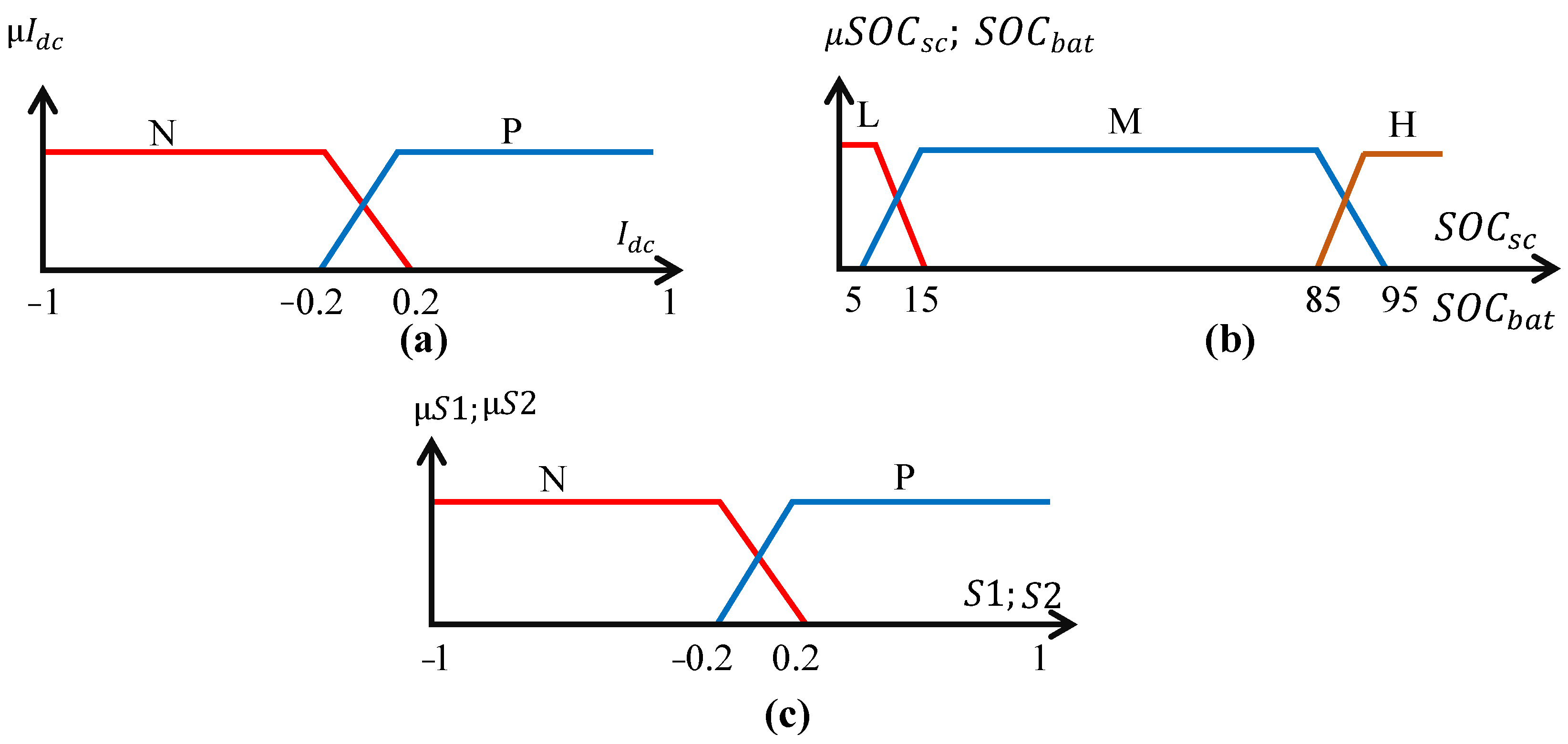
The transformation of digital inputs into linguistic outputs represents the fuzzification stage, defining membership functions (MFs) for each input. The definition of MFs is a critical step in the implementation of the fuzzy power management. The selection of MFs is based on empirical considerations, drawing on the expertise of the system. Given that the sets of fuzzy inputs determine the number of fuzzy rules, it will focus exclusively on the sets relevant to the specific case study, as shown in
Figure 9.
Two MFs are defined for the current, negative (N), and positive (P), corresponding to SC and BT charge and discharge modes, whereas the and are analyzed using three MFs: low (L), medium (M), and high (H). The low and high sets are used to prevent deep discharge and overcharge, ensuring storage system availability and protection. The medium set is used to store excess renewable energy and make up for oversubscribed power.
The sets selected for the MFs of the switches’ (S1 and S2) command signals are such that the output variable’s potential values are estimated to be between (−1 and 1).
Table 2 provides a description of the inference matrix used to identify the control rules. In fact, the same table donates the rules between
and SOC
bat to determine the control signal of the switch S
1 (S
1 allows to select between
and
depending on the
), and the same table is used for rule donation between
and
to determine S
2 control signal (S
2 allows one to select between
and
depending on
).
5.2.2. BT and SC Precise Reference Current Selection
Fuzzy logic (BT and SC control) is used to choose the exact reference current for BTs and SCs by keeping each storage system’s state of charge within reasonable bounds, and so protecting them from overcharging and excessive discharge. Four inputs (
,
,
,
) and two outputs (
,
) are considered, as shown in
Figure 10.
Three MFs are taken into account for both battery and SC current, negative (N), zero (Z), and positive (P). These are selected to meet the requirements of the proposed control strategy, where N and P correspond to discharge and charge modes, respectively. Similarly, the and are considered using three MFs: low (L), medium (M), and high (H).
Table 3 represents the inference matrix, used to define the control rules linking the fuzzy inputs and outputs. Indeed, both battery and the supercapacitor reference currents are determined based on the rules outlined in this table.
6. Simulation Results and Discussion
The effectiveness of the proposed energy management strategy is tested and presented in this section for different simulation tests. The studied railway system design is already examined in [
26]. Both wind and PV power generating system are considered 3 MW. The train power is 3.5 MW, which may correspond to 3.5 MW of regenerative energy to be fed back into the SCT. All system parameters are provided in the
Appendix A and
Appendix B. The global system model was developed within MATLAB/Simulink, and the simulation results are presented for a duration of one hour.
To ensure continuous power supply of the trains and to avoid BT and SC damage related to the train operations, it is necessary to maintain the storage devices SOC at acceptable levels. In this study, the SOC is maintained between a minimum of 10% and a maximum of 90%.
The proposed simulation test involves three stations (A, B, and C) and two trains (train 1 and train 2), with the same parameters. The trains travel in opposite directions: train 1 starts from station (A) towards station (C), passing through station (B), and train 2 starts from station (C) towards station (A), passing through station (B).
6.1. Station Simulation Test
6.1.1. Simulation Test Performed on Station (A)
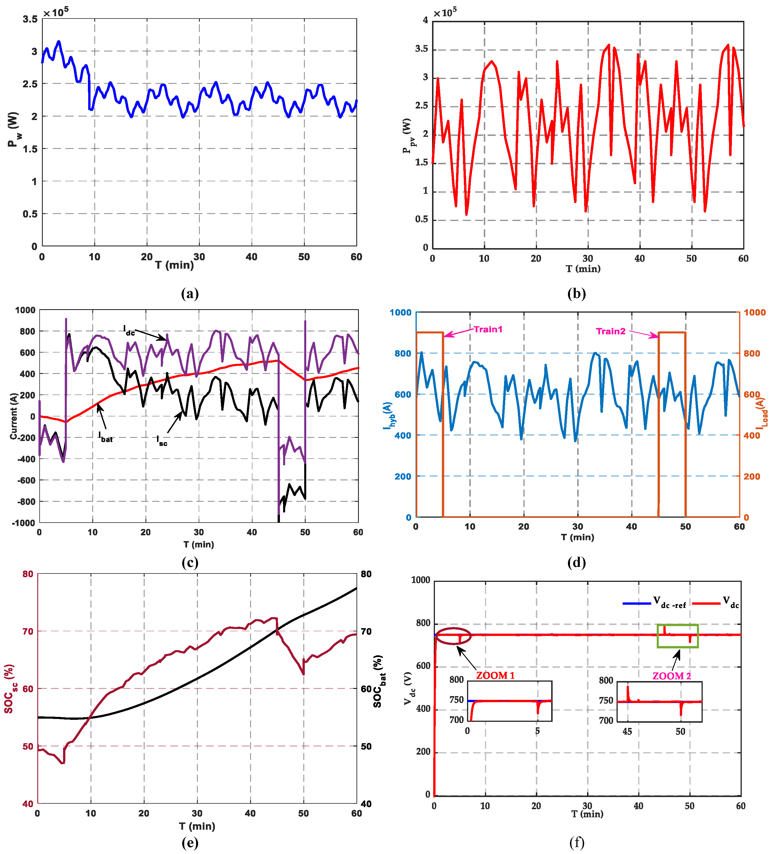
Station A is powered by the microgrid including PV and wind power sources, supported by HEES. The initial SOCs of BTs and SCs are 55% and 48%, respectively. The simulation results are displayed in
Figure 11. The generated maximum PV and wind powers are depicted in
Figure 11a,b, respectively, for variable irradiance, temperature, and wind speed.
Figure 11c shows the BT and SC reference currents over time, which vary depending on the current available in the DC bus. Accurate monitoring of these current profiles is essential to ensure correct charging and discharging of the storage components.
The hybrid station (A) and train load currents are illustrated in
Figure 11d. The hybrid current is varied between 400 A and 800 A. The two trains charge, from station (A), with a constant current (
= 900 A) during 5 min. Specifically, train 1 charges from station (A) during the interval t = 0 to t = 5 min, while train 2 arrives at station (A) at t = 45 min. The BTs’ SOC is carefully controlled, staying within the range of 55% to 78%, while the SCs’ SOC varies between 47% to 69%, as shown in
Figure 11e. Notably, regardless of changes in train load and power supply source, the batteries and supercapacitors both keep their SOC within the specified bounds.
Figure 11f displays the waveform of the DC link voltage of station (A). The voltage is well-controlled and shows a strong correlation with its reference value of 750 V. It is necessary to ensure an effective DC link voltage control in order to ensure the global system management and guarantee an efficiently operation.
6.1.2. Simulation Test on Station (B)
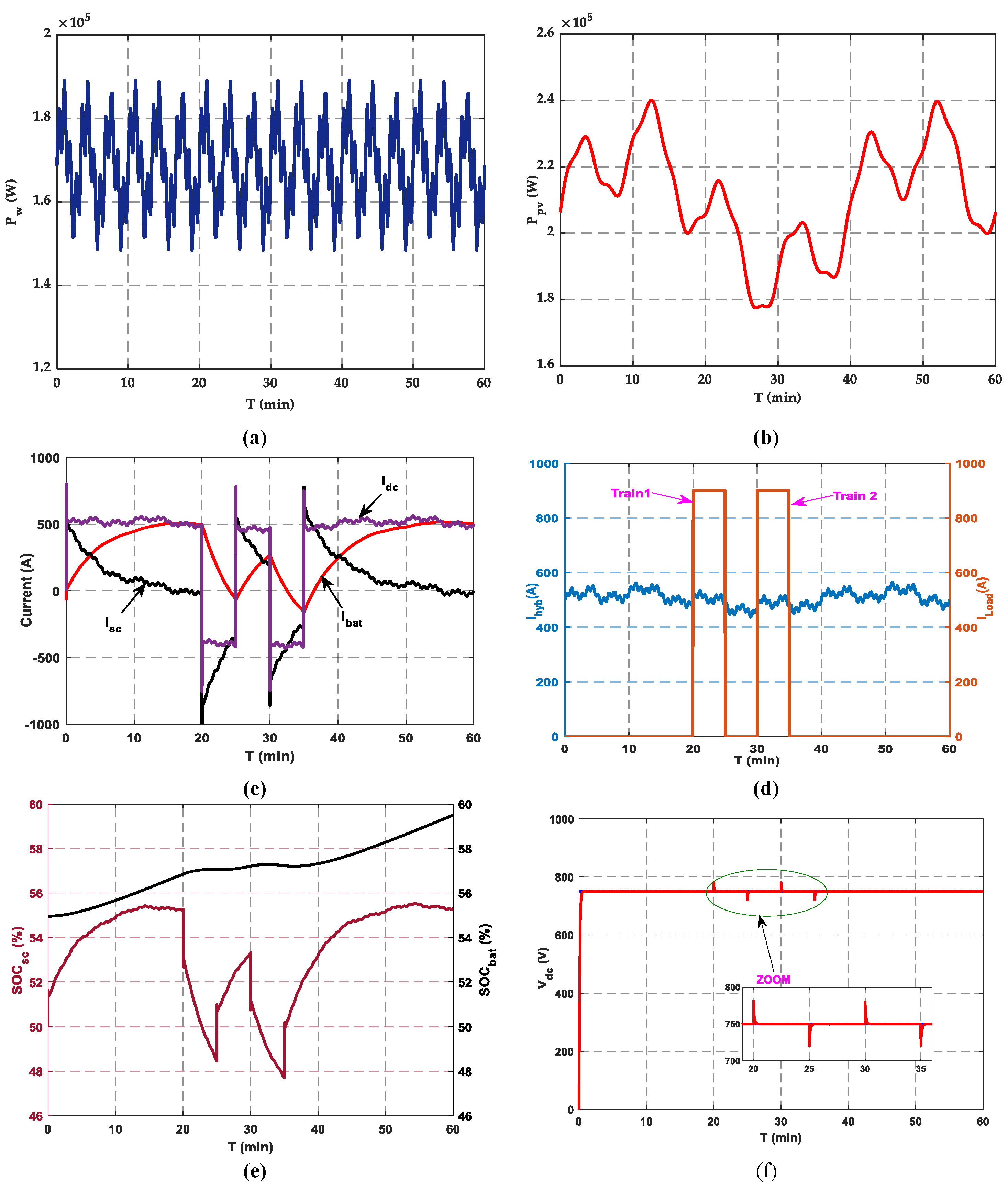
Station (B) is structurally analogous to station (A), incorporating the same microgrid configuration.
Figure 12a,b illustrate photovoltaic and wind power, respectively.
Figure 12c depicts the temporal fluctuations in BT and SC currents due to the imposed wind speed profile that causes variations in the DC bus current.
Figure 12d illustrates the hybrid source current alongside the current required by the trains. It also presents the graphic of the needed trains’ charging current when the pantographs of trains 1 and 2 are elevated to charge the SCT. In this simulation test, trains 1 and 2 are charged from station (B) for varying durations. Train 1 arrives at station (B) at t = 20 min and train 2 reaches it at t = 30 min.
Figure 12e illustrates the state of charge of the BTs and SCs. The
is precisely controlled within the range of 55% to 59.5%. The
demonstrates fluctuation, ranging from 47.7% to 55.5%. Both BTs and SCs consistently uphold their state of charge within specified limits, regardless of fluctuations in train load and power supply source. The DC link voltage of station (B), as shown in
Figure 12f, demonstrates a strong association with its reference value. The system is well regulated to attain the specified voltage, thereby sustaining a steady state at the reference value with minimal variations.
6.1.3. Simulation Test Performed on Station (C)
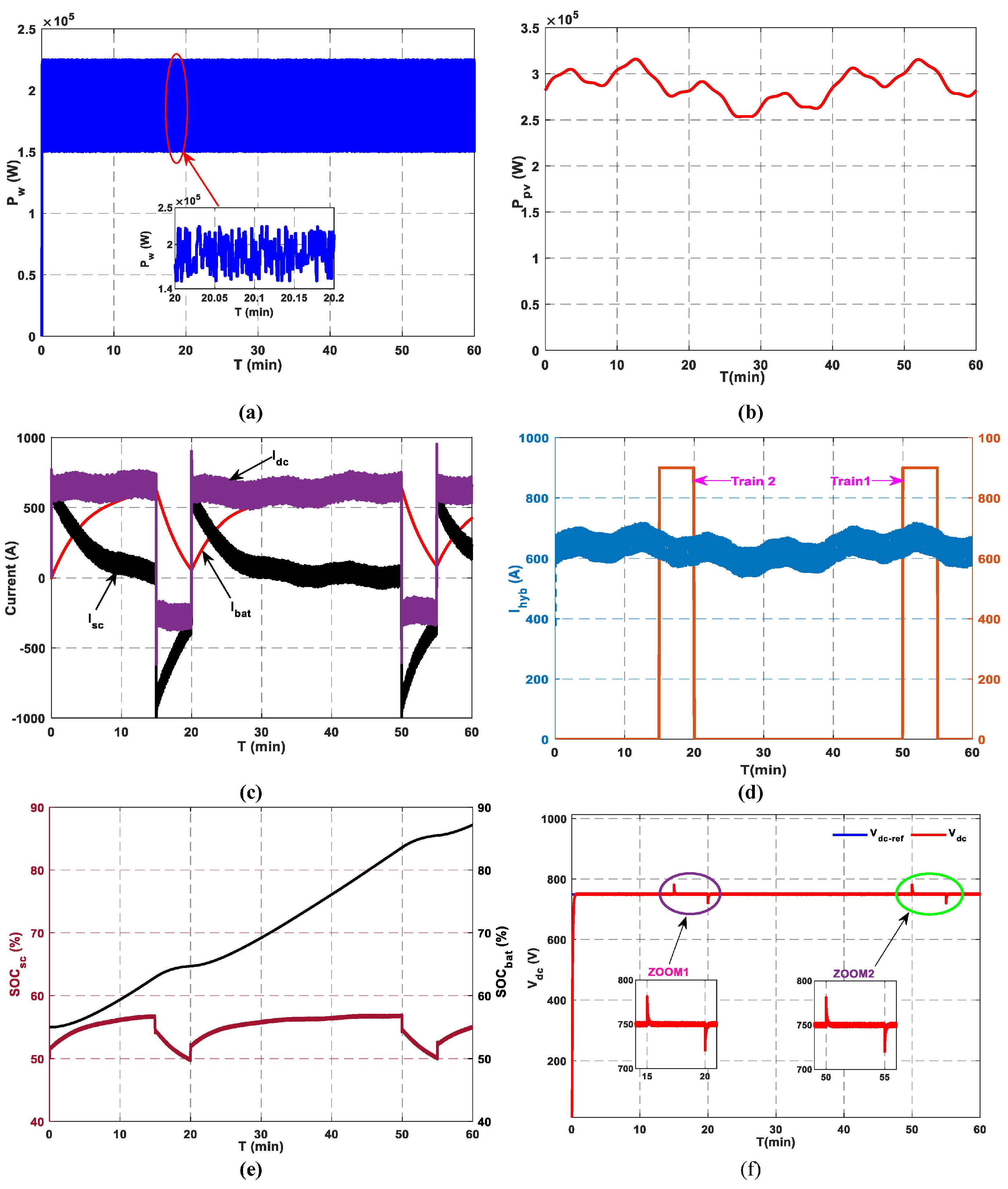
Figure 13 represents the simulation test conducted for station (C), which is structurally similar to stations (A) and (B). The incorporation of an F-EMS establishes dynamic control mechanism that not only prolongs battery life but also enhances overall system efficiency.
Figure 13a,b illustrate the generated PV and wind power, respectively. Batteries and supercapacitors’ current waveforms are illustrated in
Figure 13c. The currents of the BTs and SCs demonstrate a similar variation in reaction to the changes in the DC bus current. This current fluctuates based on the availability of DC bus current. Monitoring these current profiles is crucial to ensuring that the energy storage components are adequately charged and discharged. The F-MS adaptive performance under varying environmental conditions enhances SOC management, delivering a dependable and robust energy supply.
Figure 13d shows the hybrid source current and the charging current profiles when the pantographs of trains 1 and 2 are elevated to charge the supercapacitors at this station. In this scenario, train 2 arrives at station (C) at t = 15 min, followed by train 1 at t = 50 min, leading to distinct charging intervals for each train. Both trains draw from station C with an identical steady current (
A).
An analysis of the SOC patterns over the course of the extensive simulation period (
Figure 13e) provides crucial insights into energy storage dynamics. The SOC trends clearly illustrate the dynamic charging and discharging cycles of the BTs and SCs, which effectively respond to fluctuations in irradiance, wind speed, and train current demand. This dynamic behavior underscores the adaptability of the BTs and SCs to balance charging/discharging modes, playing a significant role in maintaining system stability. The SOC
bat is subject to stringent regulation, operating within a range of 55% and 87.2%. In contrast, the SOC
sc demonstrates variability, fluctuating between 50% and 56%. The simulation results presented in
Figure 13f confirm the stability of the DC bus voltage over the entire 60 min period, validating the accuracy and speed response of the implemented control strategy.
These results confirm that the proposed F-EMS successfully achieves the intended objectives of the hybrid system, including stable energy supply, efficient storage utilization, and reliable system operation under varying conditions.
6.2. Train Simulation Test
The energy storage technology used for the train system is based on supercapacitors. The module chosen for the train is the BMOD0063 P125 B08SC, manufactured by Maxwell Technologies [
57]. The simulation procedure was implemented considering SCT with the features reported in
Appendix B.
6.2.1. Simulation Test of Train 1
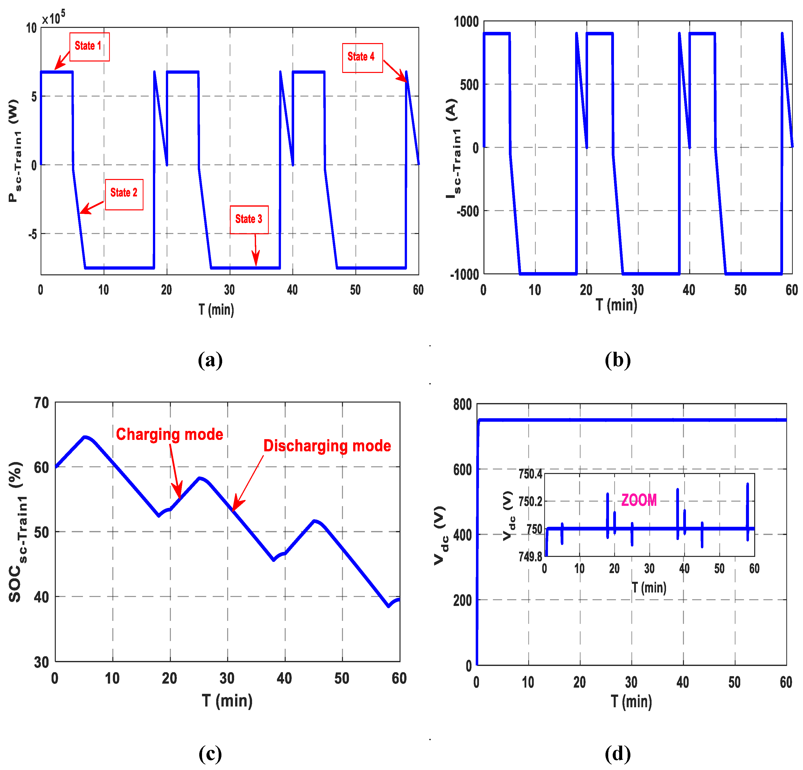
The train’s operating cycle is divided into four traction states: acceleration, constant speed operation, braking, and stop. These phases correspond to two charging and discharging modes of the SC
T. Each duty cycle is executed over a fixed duration of approximately 20 min. Acceleration begins at the departure of each station and then establishes a constant operating speed, while braking depends on the next arrival station.
Figure 14a,b show the power and current of the SCT during stopping, acceleration, cruising, and braking. It should be noted that power is positive in both charging and braking modes while it is negative in traction mode.
State1: Stopping and SCT charging
In this state, the train receives electrical power from the microgrid stations through a pantograph. Train 1 arrives at station (A) at t = 0 min and departs after 5 min. During this period, the SCT is charged with a constant current of 900 A. It charges with a same current from station B between t = 20 and t = 25 min, and at station C between t = 40 and t = 45 min. Throughout this period, traction power is zero. After an SCT charge, the pantograph takes a few seconds to descend. At the end of this state, the train is electrically isolated and moves on to the next station.
State2: Departure and acceleration phase
The train proceeds to the next station, drawing the necessary acceleration current from the SCT. During this phase, it remains disconnected from the microgrid station. This state occurs during the intervals [5–7] min, [25–27] min, and [45–47] min.
State3: Constant operating speed
This state corresponds to the time intervals [7–18] min, [27–38] min, and [47–58] min, during which the train is in movement. In this phase, the SCT power is negative, corresponding to the traction mode and the SOCsc decreases.
State4: Braking phase
A significant quantity of regenerative current is generally produced, with storage being utilized predominantly. At the end of this phase, train 1 arrives at the station and begins to recharge. This state corresponds to the time intervals [18–20] min, [38–40] min, and [58–60] min. The SOC
sc waveform of train 1 is given in
Figure 14c, varies between 65% and 38.5%, indicating an augmentation during charging mode and reduction during traction mode. The DC bus voltage of SCT is given in
Figure 14d. It follows its reference value of 750 V.
6.2.2. Simulation Test of Train 2
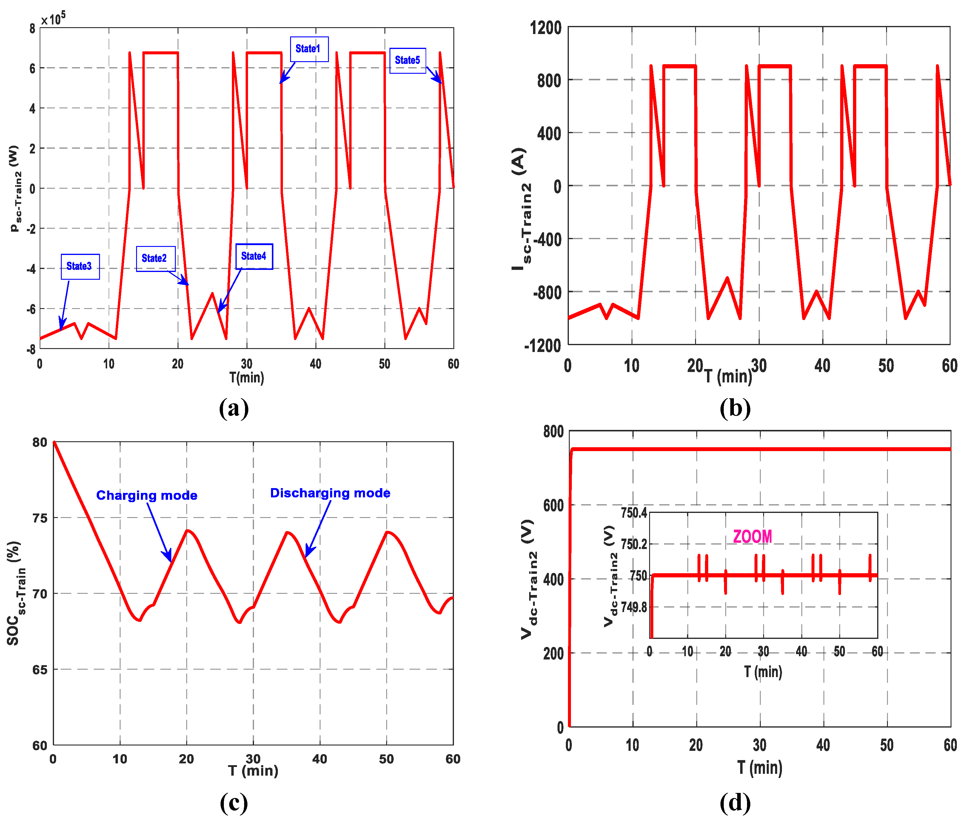
The simulated operating cycle, including the SCT charging and discharging modes, is shown in
Figure 15. The SCT power and current are negative in traction mode and positive during charging/braking modes.
State 1: Stopping and SCT Charging
Train 2 charges with a constant current of 900 A from station (C) between t = 15 min and t = 20 min, and again from station (B) between t = 30 min and t = 35 min. Upon reaching station (A), it resumes charging between t = 45 min and t = 50 min with the same current. In this state, the station supplies the train with electricity via the pantograph connected to the overhead line.
State 2: State of departure and acceleration
The train moves on to the next station. The SCT supplies the current required for acceleration. The train is currently disconnected from the microgrid station. The instants t = 20 min to t = 22 min, t = 35 min to t = 37 min, and t = 50 min to t = 53 min all correspond to this state.
State 3: State of coasting
Driving resistance usually leads to natural deceleration of the train. However, on tracks with negative gradients, velocity may rise. This operational state corresponds to the instants from t = 0 min to t = 5 min, t = 22 min to t = 25 min, t = 37 min to t = 39 min, and t = 53 min to t = 55 min.
State 4: Re-acceleration
To restore the train’s velocity to the typical operating range following a coasting phase, a re-acceleration operation is carried out.
State 5: Arrival braking
This state corresponds to the instants from t = 13 min to t = 15 min, from t = 28 min to t = 30 min, from t = 43 min to t = 45 min, and from t = 58 min to 60 min. During these periods, a significant amount of regenerative current is typically generated. At the end of this phase, train 2 reaches the station and begins the recharging process. The SOC of SCT is given in
Figure 15c, showing a variation between 80% and 69.5%. This reflects an increase during the charging mode and a decrease during traction. The DC bus voltage of train 2 is given in
Figure 15d.
6.2.3. Comparative Performance Analysis of F-EMS for Three Charging Stations
Simulations carried out on the three stations demonstrate the effectiveness and robustness of the fuzzy energy management system in a hybrid microgrid dedicated to supplying electric trains. This system manages to keep the DC bus voltage stable around its nominal value of 750 V, thus guaranteeing uninterrupted power supply. It also ensures that the batteries and supercapacitors’ states of charge are rigorously controlled, keeping them within their safe operating range to avoid overcharging or deep discharge. Through its real-time adaptation capability, the F-EMS dynamically adjusts charge and discharge currents according to variations in load and the availability of renewable sources.
The obtained results from the three stations highlight several important conclusions:
- -
SCs have played an essential role in absorbing current peaks and stabilizing rapid fluctuations, particularly in Station C. Their more dynamic operation than batteries fully justifies their integration into the system.
- -
Precise management of the state of charge is a key factor in guaranteeing system reliability. F-EMS manages to avoid deep discharges or overloads, while ensuring an efficient energy response.
A detailed summary of the F-EMS performance metrics for each station is presented in
Table 4.
7. Conclusions
Renewable energies sources (RESs) have been increasingly used for railway traction, especially as environmental concerns grow regarding conventional grid-based electrification. Integrating railway systems with station-based RESs is a promising way for improving the efficiency of urban transport networks. The studied railway application consists of a stationary hybrid RES (photovoltaic/wind) associated to an HESS (BTs and SCs) located in station. The trains are equipped with SCTs as storage devices, for their advantage of rapid charging and discharging.
An effective energy management strategy is essential for the reliable operation of such a hybrid energy storage system. In this work, a fuzzy-based energy management system is proposed for dynamically selecting the appropriate reference currents for the HESS. This selection is based on real-time monitoring of the SOC of each storage component, thereby maintaining SOC levels within safe operating limits. This approach improves both the performance and lifespan of the storage devices. Furthermore, the F-EMS guarantees power balance within the microgrid and maintains DC bus voltage stability. To evaluate the effectiveness of the proposed strategy, simulation tests were conducted in MATLAB/Simulink on a railway system comprising three stations and two trains, under varying conditions of irradiance, wind speed, and load demand.
Further simulation tests were carried out by considered the traction states (acceleration, constant speed operation, braking, and stop) during each operating cycle and the results show the potential of F-EMS to manage railway system operation with a high degree of accuracy and mastery.
The obtained results clearly demonstrated the effectiveness of the proposed approach in numerous elements of system operation. Specifically, the F-EMS successfully stabilized the DC bus voltage, ensured the delivery of sufficient load current to meet the trains’ power demands, and efficiently regulated the power flow between the BTs and SCs. The remained within safe limits, ranging from 55% to 78% in Station A, 55% to 59.5% in Station B, and 55% to 87.2% in Station C. Similarly, the was maintained within optimal boundaries, between 47% and 69% at Station A, 47.7% and 55.5% at Station B, and 50% and 56.9% at Station C. These findings verify the resilience and flexibility of the proposed F-EMS under varied operating circumstances and energy demand scenarios.
Future works will focus on extending the simulation framework to longer durations, incorporating seasonal variations and larger-scale systems with more trains and stations. The integration of electric vehicles at railway stations, through vehicle-to-grid strategies, is also a promising avenue to enhance grid flexibility and resilience. Additionally, a comparative study between F-EMS and existing EMS approaches such as RBC, DBC, FBC, and AI would offer deeper insights into performance advantages. Further improvements could involve the automatic optimization of fuzzy rules and experimental validation, paving the way for real-world deployment. Furthermore, the application of other recent metaheuristic algorithms will be explored to enhance decision-making and control precision in complex, dynamic environments.
Author Contributions
Conceptualization, I.H.; Methodology, I.H.; Software, I.H. and S.L.B.; Validation, K.I.; Formal analysis, S.L.B. and K.I.; Investigation, I.H.; Resources, I.H., K.I. and S.L.B.; Writing—original draft, H.A.; Writing—review & editing, S.L.B., H.A. and K.B.; Visualization, K.I. and S.L.B.; Supervision, S.L.B. and K.I.; Project administration, S.L.B. and K.I. All authors have read and agreed to the published version of the manuscript.
Funding
The project presented in this paper is supported by the Laboratory of Industrial Technology and Information (LTII) at the University of Bejaia, under the patronage of the General Directorate of Scientific Research and Technological Development (DGRSDT), Algeria.
Institutional Review Board Statement
Not applicable.
Informed Consent Statement
Not applicable.
Data Availability Statement
Data are contained within the article.
Conflicts of Interest
The authors declare no conflict of interest.
Abbreviations
| Mechanical gearbox ratio |
| G | Solar irradiation |
| T | Ambient temperature |
| Wind turbine speed |
| Photocurrent |
| Shunt current |
| Serial resistance of PV panel |
| Power coefficient of the turbine |
| Swept area of the wind turbine |
| Wind velocity |
| , | d-q stator voltages |
| Secondary capacity |
| , | The d-q stator currents |
| , | Leakage inductances |
| Density of the air |
| Stator phase resistance |
| The emf that models the no-load voltage of the battery |
| Internal resistance of the battery |
| Current through the capacitance |
| Capacitance voltage of the battery |
| Nominal capacity of the battery |
| Amount of electric charge |
| Constant parameters |
| Primary capacitance |
| Constant capacitance |
| Voltage of the first branch of the supercapacitor |
| DC bus capacitor |
| DC bus voltage |
| Current generated by the wind turbine |
| Battery current |
| Supercapacitor current |
| Load current |
| Maximum state of charge of the battery |
| Minimum state of charge of the battery |
| State of charge of the battery |
| Maximum state of charge of the supercapacitor |
| Minimum state of charge of the supercapacitor |
| State of charge of the supercapacitor |
| Total direct current |
Appendix A
Table A1.
HESS parameters.
Table A1.
HESS parameters.
| | Parameters | Values |
|---|
| SC Model Parameters | | |
| | Rated capacitance
Maximum ESRDC initial
Test current for capacitance and ESRDC
Rated voltage
Absolute maximum voltage
Absolute maximum current
Maximum series voltage
SOCmax
SOCmin | 165 F
60 m
100 A
48 V
51 V
1900 A
750 V
90%
10% |
| BT Model Parameters | | |
| | Nominal voltage
Nominal capacity
Internal resistance
SOCmax
SOCmin | 12 V
100 Ah
0.08
90%
10% |
Appendix B
Table A2.
SCT parameters.
Table A2.
SCT parameters.
| SCT Model Parameters |
|---|
| Capacitance | 63 F |
| Rated voltage | 125 V |
| Stored Energy | 140 Wh |
| Nominal Voltage | 750 V |
| Maximum series voltage | 1500 V |
| Absolute maximum current | 1900 A |
References
- Ye, J.; Sun, M.; Song, K. An Energy Management Strategy for an Electrified Railway Smart Microgrid System Based on Integrated Empirical Mode Decomposition. Energies 2024, 17, 268. [Google Scholar] [CrossRef]
- Roch-Dupre, D.; Gonsalves, T.; Cucala, A.P.; Pecharroman, R.R.; Lopez-Lopez, A.J.; Fernandez-Cardador, A. Multi-stage optimization of the installation of Energy Storage Systems in railway electrical infrastructures with nature-inspired optimization algorithms. Eng. Appl. Artif. 2021, 104, 104370. [Google Scholar] [CrossRef]
- Kleftakis, V.A.; Hatziargyriou, N.D. Optimal control of reversible substations and wayside storage devices for voltage stabilization and energy savings in metro railway networks. IEEE Trans. Transp. Electrif. 2019, 5, 515–523. [Google Scholar] [CrossRef]
- Darvishpour, Y.; Mousavi Gazafrudi, S.M.; Jafari Kaleybar, H.; Brenna, M. Integration of Rooftop Solar PV on Trains: Comparative Analysis of MPPT Methods for Auxiliary Power Supply of Locomotives in Milan. Electronics 2024, 13, 3537. [Google Scholar] [CrossRef]
- Chen, Z.; Jiang, M.; Qi, L.; Wei, W.; Yu, Z.; Wei, W.; Yu, X.; Yan, J. Using existing infrastructures of high-speed railways for photovoltaic electricity generation. Resour. Conserv. Recycl. 2022, 178, 106091. [Google Scholar] [CrossRef]
- Ukoba, K.; Yoro, K.O.; Eterigho-Ikelegbe, O.; Ibegbulam, C.; Jen, T.C. Adaptation of solar power in the Global south: Prospects, challenges and opportunities. Heliyon 2024, 10, e28009. [Google Scholar] [CrossRef] [PubMed]
- Bade, S.K.; Kulkarni, V. Use of renewable energy in performance enhancement of Indian traction power supply system. In Proceedings of the 2018 International Conference on Smart Electric Drives and Power System (ICSEDPS), Nagpur, India, 12–13 June 2018; IEEE: Piscataway, NJ, USA, 2018; pp. 111–116. [Google Scholar]
- Park, S.; Salkuti, S.R. Optimal energy management of railroad electrical systems with renewable energy and energy storage systems. Sustainability 2019, 11, 6293. [Google Scholar] [CrossRef]
- Singh, L.; Vaishnav, C.; Shrivastava, V. Performance analysis of hybrid network of Indian traction power system using renewable energy sources. In Proceedings of the 2016 International Conference on Micro-Electronics and Telecommunication Engineering (ICMETE), Ghaziabad, India, 22–23 September 2016; IEEE: Piscataway, NJ, USA, 2016; pp. 611–615. [Google Scholar]
- Bade, S.K.; Kulkarni, V. Analysis of railway traction power system using renewable energy: A review. In Proceedings of the 2018 International Conference on Computation of Power, Energy, Information and Communication (ICCPEIC), Chennai, India, 28–29 March 2018; IEEE: Piscataway, NJ, USA, 2018; pp. 404–408. [Google Scholar]
- Elisabeta, S.; Bogdan, P.; Ion, P.; Valentin, N.; Florina, P. Use of Renewable Energy Sources to Power Railroad Traffic Safety Installations. In Proceedings of the 2019 11th International Symposium on Advanced Topics in Electrical Engineering (ATEE), Bucharest, Romania, 28–30 March 2019; IEEE: Piscataway, NJ, USA, 2019; pp. 1–4. [Google Scholar]
- Bakre, S.; Gokhale, P. Neural Network based source selection scheme for wind-solar based auxiliary supply in Railway Traction Systems. In Proceedings of the 2020 IEEE Pune Section International Conference (PuneCon), Pune, India, 16–18 December 2020; IEEE: Piscataway, NJ, USA, 2020; pp. 191–194. [Google Scholar]
- Yu, H.; Wang, Y.; Chen, Z. A renwable electricity-hydrogen-integrated hybrid DC traction power system. In Proceedings of the 2021 IEEE Southern Power Electronics Conference (SPEC), Kigali, Rwanda, 6–9 December 2021; IEEE: Piscataway, NJ, USA, 2021; pp. 1–6. [Google Scholar]
- Di Noia, L.P.; Rizzo, R. Analysis of integration of PV power plant in railway power systems. In Proceedings of the 2019 8th International Conference on Modern Power Systems (MPS), Cluj Napoca, Romania, 21–23 May 2019; IEEE: Piscataway, NJ, USA, 2019; pp. 1–5. [Google Scholar]
- Rageh, M.; Ndtoungou, A.; Hamadi, A.; Al-Haddad, K. Railway traction supply with PV integration for power quality issues. In Proceedings of the IECON 2018—44th Annual Conference of the IEEE Industrial Electronics Society, Washington, DC, USA, 21–23 October 2018; IEEE: Piscataway, NJ, USA, 2018; pp. 1436–1441. [Google Scholar]
- Wu, C.; Han, B.; Lu, S.; Xue, F.; Zhong, F. Carbon-reducing Train Rescheduling Method for Urban Railway Systems considering the Grid with Wind Power Supply. In Proceedings of the 2022 IEEE 25th International Conference on Intelligent Transportation Systems (ITSC), Macau, China, 8–12 October 2022; IEEE: Piscataway, NJ, USA, 2022; pp. 164–169. [Google Scholar]
- Mahmud, M.A.; Roy, T.K.; Saha, S.; Haque, M.E.; Pota, H.R. Robust nonlinear adaptive feedback linearizing decentralized controller design for islanded DC microgrids. IEEE Trans. Ind. Appl. 2019, 55, 5343–5352. [Google Scholar] [CrossRef]
- Azizi, A.; Peyghami, S.; Mokhtari, H.; Blaabjerg, F. Autonomous and decentralized load sharing and energy management approach for DC microgrids. Electr. Power Syst. Res. 2019, 177, 106009. [Google Scholar] [CrossRef]
- Roy, T.K.; Mahmud, M.A. Dynamic stability analysis of hybrid islanded DC microgrids using a nonlinear backstepping approach. IEEE Syst. J. 2017, 12, 3120–3130. [Google Scholar] [CrossRef]
- Whaite, S.; Grainger, B.; Kwasinski, A. Power quality in DC power distribution systems and microgrids. Energies 2015, 8, 4378–4399. [Google Scholar] [CrossRef]
- Han, Y.; Chen, W.; Li, Q. Energy management strategy based on multiple operating states for a photovoltaic/fuel cell/energy storage DC microgrid. Energies 2017, 10, 136. [Google Scholar] [CrossRef]
- Lu, Y.; Liu, Z.; Lyu, J.; Wei, X. Hierarchical Power Allocation Control for Star-Connected Hybrid Energy Storage System Using Cascaded Multilevel Converters. Front. Energy Res. 2021, 9, 748508. [Google Scholar] [CrossRef]
- Ghosh, S.K.; Roy, T.K.; Pramanik, M.A.H.; Sarkar, A.K.; Mahmud, M.A. An energy management system-based control strategy for DC microgrids with dual energy storage systems. Energies 2020, 13, 2992. [Google Scholar] [CrossRef]
- Yin, C.; Wu, H.; Locment, F.; Sechilariu, M. Energy management of DC microgrid based on photovoltaic combined with diesel generator and supercapacitor. Energy Convers. Manag. 2017, 132, 14–27. [Google Scholar] [CrossRef]
- Javed, K.; Ashfaq, H.; Singh, R.; Hussain, S.S.; Ustun, T.S. Design and performance analysis of a stand-alone PV system with hybrid energy storage for rural India. Electronics 2019, 8, 952. [Google Scholar] [CrossRef]
- Cabrane, Z.; Lee, S.H. Control and management of railway system connected to microgrid stations. IEEE Access 2022, 10, 40445–40455. [Google Scholar] [CrossRef]
- Tabart, Q.; Vechiu, I.; Etxeberria, A.; Bacha, S. Hybrid energy storage system microgrids integration for power quality improvement using four-leg three-level NPC inverter and second-order sliding mode control. IEEE Trans. Ind. Electron. 2018, 65, 424–435. [Google Scholar] [CrossRef]
- Hacini, I.; Lalouni, S.; Idjdarene, K.; Berabez, K. Energy management of a photovoltaic system with hybrid energy storage battery-super capacitor. J. Renew. Energ. 2023, 1, 65–74. [Google Scholar] [CrossRef]
- Pattnaik, S.; Kumar, M.R.; Mishra, S.K.; Gautam, S.P.; Appasani, B.; Ustun, T.S. DC bus voltage stabilization and SOC management using optimal tuning of controllers for supercapacitor based PV hybrid energy storage system. Batteries 2022, 8, 186. [Google Scholar] [CrossRef]
- Srikanth, D.; Sukumar, G.D.; Sobhan, P.V. A convolutional neural network based energy management system for photovoltaic/battery systems in microgrid using enhanced coati optimization approach. J. Energy Storage 2025, 119, 116252. [Google Scholar] [CrossRef]
- Rekioua, D.; Kakouche, K.; Babqi, A.; Mokrani, Z.; Oubelaid, A.; Rekioua, T.; Azil, A.; Ali, E.; Alaboudy, A.H.K.; Abdelwahab, S.A.M. Optimized Power Management Approach for Photovoltaic Systems with Hybrid Battery-Supercapacitor Storage. Energies 2023, 15, 14066. [Google Scholar] [CrossRef]
- Bocklisch, T. Hybrid energy storage approach for renewable energy applications. J. Energy Storage 2016, 8, 311–319. [Google Scholar] [CrossRef]
- Alnejaili, T.; Drid, S.; Mehdi, D.; Chrifi-Alaoui, L.; Belarbi, R.; Hamdouni, A. Dynamic control and advanced load management of a stand-alone hybrid renewable power system for remote housing. Energy Convers. Manag. 2015, 105, 377–392. [Google Scholar] [CrossRef]
- Hajiaghasi, S.; Salemnia, A.; Hamzeh, M. Hybrid energy storage system for microgrids applications: A review. J. Energy Storage 2019, 21, 543–570. [Google Scholar] [CrossRef]
- Ramos, G.A.; Costa-Castelló, R. Energy management strategies for hybrid energy storage systems based on filter control: Analysis and comparison. Electronics 2022, 11, 1631. [Google Scholar] [CrossRef]
- Kabouri, O.; Azeroual, M.; El Markhi, H.; Bagayogo, A. A Novel Fuzzy Logic EMS for Hybrid Microgrids with Photovoltaic, Wind, Fuel Cell, and Energy Storage Integration. E3S Web of Conf. 2025, 601, 00059. [Google Scholar] [CrossRef]
- Cao, J.; Du, W.; Wang, H.; McCulloch, M. Optimal sizing and control strategies for hybrid storage system as limited by grid frequency deviations. IEEE Trans. Power Syst. 2018, 33, 5486–5495. [Google Scholar] [CrossRef]
- Nivolianiti, E.; Karnavas, Y.L.; Charpentier, J.F. Fuzzy logic-based energy management strategy for hybrid fuel cell electric ship power and propulsion system. J. Mar. Sci. Eng. 2024, 12, 1813. [Google Scholar] [CrossRef]
- Gamage, D.; Zhang, X.; Ukil, A. Fuzzy logic controller for efficient energy management of a PV system with HESS. In Proceedings of the IECON 2018—44th Annual Conference of the IEEE Industrial Electronics Society, Washington, DC, USA, 21–23 October 2018; IEEE: Piscataway, NJ, USA, 2018; pp. 3556–3561. [Google Scholar]
- Şen, M.; Özcan, M.; Eker, Y.R. Fuzzy logic-based energy management system for regenerative braking of electric vehicles with hybrid energy storage system. Appl. Sci. 2024, 14, 3077. [Google Scholar] [CrossRef]
- Chong, L.W.; Wong, Y.W.; Rajkumar, R.K.; Isa, D. An optimal control strategy for standalone PV system with Battery-Supercapacitor Hybrid Energy Storage System. J. Power Sources 2016, 331, 553–565. [Google Scholar] [CrossRef]
- Davoodi, M.; Jafari Kaleybar, H.; Brenna, M.; Zaninelli, D. Energy Management Systems for Smart Electric Railway Networks: A Methodological Review. Sustainability 2023, 15, 12204. [Google Scholar] [CrossRef]
- Kilinc-Ata, N.; Fikru, M.G. A Framework for Evaluating EV Battery Mineral Sourcing Challenges. Sustain. Futur. 2025, 9, 100720. [Google Scholar] [CrossRef]
- Pierrou, G.; Valero-De la Flor, C.; Hug, G. Optimal EV charging scheduling at electric railway stations under peak load constraints. Electr. Power Syst. Res. 2024, 235, 110612. [Google Scholar] [CrossRef]
- Zidane, N.; Belaid, S.L. Energy management for renewable electricity production system including hybrid hydrogen sub-system. J. Renew. Energ. 2023, 1, 107–115. [Google Scholar] [CrossRef]
- Deboucha, H.; Belaid, S.L. Improved incremental conductance maximum power point tracking algorithm using fuzzy logic controller for photovoltaic system. Rev. Roum. Sci. Techn.–Electrotechn. Energ. 2017, 62, 381–387. [Google Scholar]
- Boudjerda, T.; Belaid, S.L.; Tamalouzt, S. Fuzzy energy management for a standalone Photovoltaic/batteries/load System. In Proceedings of the 2024 International Conference on Advances in Electrical and Communication Technologies (ICAECOT), Setif, Algeria, 1–3 October 2024; IEEE: Piscataway, NJ, USA, 2024; pp. 1–6. [Google Scholar]
- Krumbein, S.; Jentzsch, M.; Saverin, J.; Nayeri, C.; Paschereit, C. The Underwater Berlin Research Turbine: A Wind Turbine Model for Wake Investigations in a Water Towing Tank. J. Phys. Conf. Ser. 2024, 2767, 042011. [Google Scholar] [CrossRef]
- Belaid, S.L.; Idjdarene, K. Design and control of hybrid (photovoltaic/wind) water pumping system in Bejaia area. In Proceedings of the International Conference on Electronics and Electrical Engineering (IC3E 2018), Bouira, Algeria, 12–13 November 2018; Volume 50, p. 2. [Google Scholar]
- Idjdarene, K.; Rekioua, D.; Rekioua, T.; Tounzi, A. Vector Control of Autonomous Induction Generator with Battery Storage System. In Proceedings of the 2017 International Renewable and Sustainable Energy Conference (IRSEC), Tangier, Morocco, 4–7 December 2017; IEEE: Piscataway, NJ, USA, 2017; pp. 1–6. [Google Scholar]
- Sahri, Y.; Tamalouzt, S.; Belaid, S.L.; Bajaj, M.; Ghoneim, S.S.; Zawbaa, H.M.; Kamel, S. Performance improvement of Hybrid System based DFIG-Wind/PV/Batteries connected to DC and AC grid by applying Intelligent Control. Energy Rep. 2023, 9, 2027–2043. [Google Scholar] [CrossRef]
- Yachir, A.; Belabbes, A.; Boulouiha, H.M.; Bouddou, R.; Bouzid, A.E.M.; Bouchikhi, N.; Adiche, S. Improved sliding mode control of a wind turbine system based on a developed permanent magnet synchronous generator. J. Renew. Energ. 2024, 1, 203–221. [Google Scholar] [CrossRef]
- Aimene, M.; Payman, A.; Dakyo, B. Comparative study between flatness-based and field-oriented control methods of a grid-connected wind energy conversion system. Processes 2022, 10, 378. [Google Scholar] [CrossRef]
- Djoudi, O.; Lalouni, S.; Tamalouzt, S.; Ziane, D. An intelligent demand side management for stand-alone AC microgrid based on wind-DFIG/battery hybrid system. J. Electr. Syst. 2024, 20, 382–393. [Google Scholar]
- Berabez, K.; Hacini, I.; Hamoudi, F.; Idjdarene, K. Enhancement dtc control for seig in variable-speed wind turbines, associated with an energy storage system. J. Renew. Energ. 2023, 1, 87–97. [Google Scholar] [CrossRef]
- Cabrane, Z.; Lee, S.H. Electrical and mathematical modeling of supercapacitors: Comparison. Energies 2022, 15, 693. [Google Scholar] [CrossRef]
- Ciccarelli, F.; Di Noia, L.P.; Rizzo, R. Integration of Photovoltaic Plants and Supercapacitors in Tramway Power Systems. Energies 2018, 11, 410. [Google Scholar] [CrossRef]
Figure 1.
Railway system configuration.
Figure 1.
Railway system configuration.
Figure 2.
Block diagram of station configuration.
Figure 2.
Block diagram of station configuration.
Figure 3.
(a). PV panel characteristic curves with different temperature at 1000 W/m2. (b). PV panel characteristics curves for different irradiance at 25 °C.
Figure 3.
(a). PV panel characteristic curves with different temperature at 1000 W/m2. (b). PV panel characteristics curves for different irradiance at 25 °C.
Figure 4.
Operating zones of wind turbine.
Figure 4.
Operating zones of wind turbine.
Figure 5.
Electrical circuit of battery.
Figure 5.
Electrical circuit of battery.
Figure 6.
Supercapacitor simplified circuit.
Figure 6.
Supercapacitor simplified circuit.
Figure 7.
Schematic diagram of the HESS control strategy of station.
Figure 7.
Schematic diagram of the HESS control strategy of station.
Figure 8.
Fuzzy logic energy management supervisor.
Figure 8.
Fuzzy logic energy management supervisor.
Figure 9.
Block Diagram of proposed fuzzy logic-based power flow control: (a,b) input membership functions, (c) output membership functions.
Figure 9.
Block Diagram of proposed fuzzy logic-based power flow control: (a,b) input membership functions, (c) output membership functions.
Figure 10.
Block diagram of proposed fuzzy logic-based SOC control (input and output membership functions).
Figure 10.
Block diagram of proposed fuzzy logic-based SOC control (input and output membership functions).
Figure 11.
Simulation test of station A. (a) Wind power. (b) Photovoltaic power. (c) BT and SC currents of station A. (d) Hybrid current and charge current from station A. (e) SOC of BTs and SCs of station A. (f) DC bus voltage of station.
Figure 11.
Simulation test of station A. (a) Wind power. (b) Photovoltaic power. (c) BT and SC currents of station A. (d) Hybrid current and charge current from station A. (e) SOC of BTs and SCs of station A. (f) DC bus voltage of station.
Figure 12.
Simulation test of station (B). (a) Wind power. (b) Photovoltaic power. (c) BT and SC currents of station B. (d) Hybrid current and charge current from station B. (e) SOC of BTs and SCs of station B. (f) DC bus voltage of station.
Figure 12.
Simulation test of station (B). (a) Wind power. (b) Photovoltaic power. (c) BT and SC currents of station B. (d) Hybrid current and charge current from station B. (e) SOC of BTs and SCs of station B. (f) DC bus voltage of station.
Figure 13.
Simulation test of station (C). (a) Wind power. (b) Photovoltaic power. (c) BT and SC currents of station C. (d) Hybrid current and charge current from station C. (e) SOC of BTs and SCs of station C. (f) DC bus voltage of station.
Figure 13.
Simulation test of station (C). (a) Wind power. (b) Photovoltaic power. (c) BT and SC currents of station C. (d) Hybrid current and charge current from station C. (e) SOC of BTs and SCs of station C. (f) DC bus voltage of station.
Figure 14.
Simulation test of train 1 moving from station (A) to station (C): (a) SCT power profile from station (A) to station (C). (b) Current required to the SCT. (c) SCT state of charge. (d) DC bus voltage.
Figure 14.
Simulation test of train 1 moving from station (A) to station (C): (a) SCT power profile from station (A) to station (C). (b) Current required to the SCT. (c) SCT state of charge. (d) DC bus voltage.
Figure 15.
Simulation test of train 2 moving from station (C ) to station (A): (a) Power profile from station C to station A. (b) Waveform of SCT current. (c) SOC of SCT. (d) DC bus voltage.
Figure 15.
Simulation test of train 2 moving from station (C ) to station (A): (a) Power profile from station C to station A. (b) Waveform of SCT current. (c) SOC of SCT. (d) DC bus voltage.
Table 1.
Comparative review of the most prominent EMS techniques.
Table 1.
Comparative review of the most prominent EMS techniques.
| Strategy | Advantages | Limitations | Contribution to
Energy Management | References |
|---|
| RBC | Simple
implementation,
suitable for
real-time control | Sensitive to parameter
changes;
Lacks adaptability | Ensures basic
energy flow
control using
predefined rules | [26,28,30,32] |
| DBC | Decentralized control,
good load sharing | Requires accurate
modeling;
Limited flexibility | Shares load efficiently
between
sources based on
voltage/current levels | [33,34] |
| FBC | Economical,
fast response | Does not
consider SOC,
less effective under highly
variable loads | Separates low/high
frequency
power demands for
storage assignment | [35] |
| FLC | Robust to
uncertainties,
no need for exact
model | Depends on
expert-defined
rules
and membership
functions | Adapts to system
fluctuations;
handles nonlinear
and uncertain systems | [36,37,38,39,40] |
FLC
with
PSO | Optimized
fuzzy control;
reduces battery
stress | More complex
design;
higher
computational
cost | Enhances FLC
performance
via PSO for better
charge/discharge
scheduling | [41] |
| ANN | Learns complex
nonlinear
patterns,
adaptive | Requires
training data;
Computationally
demanding | Predicts optimal
power
flows in dynamic
conditions | [31,34] |
| EA | Handles
multi-objective
problems;
No gradient required | Slow convergence;
Not suitable for
real-time applications | Optimizes
EMS parameters
for long-term system
efficiency | [27,29,42] |
Table 2.
S1 and S2 rules.
Table 2.
S1 and S2 rules.
| S1 and S2 | |
|---|
| L | M | H |
|---|
| P | N | N | P |
| N | P | N | N |
Table 3.
and rules.
Table 3.
and rules.
| , | , |
| L | M | H |
| . | N | Z | N | N |
| Z | Z | Z | Z |
| P | P | P | Z |
Table 4.
A summary of the F-EMS performances for the three stations (A, B, and C).
Table 4.
A summary of the F-EMS performances for the three stations (A, B, and C).
| Performances | Station A | Station B | Station C |
|---|
Train charging
time | Train 1: t = 0 min
Train 2: t = 45 min | Train 1: t = 20 min
Train 2: t = 30 min | Train 2: t = 15 min
Train 1: t = 50 min |
| Train charging current | 900 A for 5 min | 900 A for 5 min | 900 A for 5 min |
| BT SOC | 55–78% | 55–59.5% | 55–87.2% |
| SC SOC | 47–69% | 47.7–5.5% | 50–56.9% |
| BT/SC current responses | Fast response and well-controlled according to DC current | Sensitive to wind fluctuations | Well-controlled, fast dynamic response |
| DC bus voltage | Stable, close to reference Value of 750 V | Stability provided, low variations | Perfectly stable over 60 min |
| F-EMS | Good dynamic control fast response | Precise control under variable load | High adaptability and robustness |
| Disclaimer/Publisher’s Note: The statements, opinions and data contained in all publications are solely those of the individual author(s) and contributor(s) and not of MDPI and/or the editor(s). MDPI and/or the editor(s) disclaim responsibility for any injury to people or property resulting from any ideas, methods, instructions or products referred to in the content. |
© 2025 by the authors. Licensee MDPI, Basel, Switzerland. This article is an open access article distributed under the terms and conditions of the Creative Commons Attribution (CC BY) license (https://creativecommons.org/licenses/by/4.0/).


 ,
, 