Abstract
In this paper, an optimal transient control (OTC) scheme is proposed to improve the transient stability of the grid-forming (GFM) wind farm (WF) based on the transient stability of the WTs. The converter’s current operating safety range is considered to quantify the maximum KES capabilities of the WTs. At the WF control level, the global transient voltage control problem is solved by optimizing the output reactive power of different WTs of the WF. At the WT control level, the transient stability of WT is improved by regulating the output power and weak magnetic current. The simulation results in MATLAB/Simulink show that the proposed control scheme can more efficiently improve the transient stability of WT by suppressing the DC bus voltage fluctuations and enhancing the voltage support capability of WT compared with the traditional control schemes.
1. Introduction
Wind power generation is developing rapidly at home and abroad today, and the installed capacity of wind power generation is increasing annually. Compared with traditional thermal power generation, wind power has great advantages in terms of cleanliness and environmental friendliness. The wind turbine (WT) can be categorized into the following types: Direct Current (DC) generators, Alternating Current (AC) synchronous generators, AC asynchronous generators, Switched Reluctance generators, and so on. The direct-driven permanent magnet synchronous generator (D-PMSG) is often used as an AC WT [1]. The D-PMSG-based WT is connected to the grid through a full-power converter without a gearbox, which has the advantages of a simple structure, reduced losses, and low operating costs compared with the DIFG-based WT [2,3]. However, as the installed capacity and permeability of WT grow, the external grid disturbances may cause large fluctuations in the internal voltage of the WTs, and the operational stability of the grid will be seriously challenged [4,5,6].
When the grid voltage dips, the terminal voltage of the grid-side converter (GSC) will decrease, and the current GSC may exceed the maximum, which leads to a reduction in power for the GSC. However, since the rotor-side converter (RSC) and GSC control of the WT are decoupled, the RSC cannot rapidly respond to the reduction in the grid voltage, and the power of the RSC remains constant. The unbalanced power between the RSC and GSC will result in the DC bus voltage fluctuations and even threaten the safety of the whole system [7,8,9,10,11]. For example, the 8–9 large-scale blackout in the UK and the 9–28 blackout in Australia were both caused by the failure of the low voltage ride-through (LVRT) of WT after the grid voltage dropped abruptly due to irresistible factors, and the whole power system was severely threatened [12]. When the grid voltage swells, the terminal voltage of the WTs will be at risk of overvoltage and off-grid, which may even affect the stable operation of the whole WF. Therefore, it is very important to improve the transient stability and support capacities of WTs and the WF.
From the WT control level, the researchers mainly focus on the overvoltage and overcurrent problems of a single WT without considering the transient coupling between different WTs. In [13], a transient control strategy based on a superconducting magnetic energy storage cell structure was proposed to improve the voltage support capability of the WT. In [14], a low-voltage ride-through (LVRT) control method based on stator current limiter and rotor resistance (RSDR) was proposed to reduce the DFIG transient electromagnetic oscillation and enhance the fault ride-through capability. In [15], an LVRT control strategy based on a series current source converter and a superconducting magnetic energy storage device was proposed, which effectively reduces transient overcurrent and ensures the safe operation of the WT. In [16], a superconducting fault current limiter-magnetic energy storage system was developed to enhance the LVRT capability of WT. In [17], the transient behavior of WT under symmetrical and asymmetrical grid voltage dip faults was comprehensively analyzed, and this paper proposed a novel LVRT control method to improve the fault ride-through capability of WT. The control methods proposed in the above literature mitigate the problem of overvoltage and overcurrent in WTs to some extent. However, the transient power flow and transient operation mechanism of WTs have not been revealed, and the transient support capability of the WTs cannot be fully utilized. In addition, in large wind farm clusters comprising numerous large-scale WTs, the interdependence between the injected power and voltage fluctuations across multiple turbines becomes more pronounced. Due to the influence of complex environmental conditions, the power output and terminal voltages of WTs can experience significant fluctuations, sometimes exceeding the thresholds specified by grid codes.
From the WF control level, the large-scale WF transient voltage problems are solved by optimally regulating the output power of the WTs, but the transient support potential and the maximum transient voltage support capacities of WTs are not considered. In [18], a multi-mode matching control approach is proposed to enhance support to the onshore grid while preserving fault ride-through capability. In [19], a coordinated control method utilizing harmonic injection is introduced to rapidly limit the voltage of Modular Multilevel Converters (MMCs) within permissible ranges. These control schemes address the issue of MMC voltage and WT terminal voltage fluctuations from the wind farm system level. In [20], a P-Q coordinated high-voltage ride-through (HVRT) control strategy is proposed to provide optimal dynamic voltage support for WF. However, the multi-level physical quantity coupling mechanisms in large-scale wind turbines remain unclear, and the anti-disturbance and active support capabilities of the WTs are still inadequate.
Energy storage systems can be used to increase reactive power support and reduce wind energy losses, but additional installation and warranty costs are unavoidable. The kinetic energy storage (KES) of WTs can achieve the same performance without additional installation, which is mainly used to solve the frequency fluctuation issues. In [21], the relationship between the system frequency variation and active power was established to leverage the KES of the WT for primary frequency regulation. In [22], a distributed cooperative control scheme is introduced, designed to rapidly reduce system frequency fluctuations by considering the maximum KES capacity of the WTs. In [23], a novel control strategy for WF active power regulation is proposed, and it takes the KES capacity of different WTs into account to mitigate frequency fluctuations during system load changes. However, how to accurately quantify and fully utilize the KES capabilities of different WTs to improve the transient stability and support capability is something that needs to be investigated.
To tackle the above problems, an optimal transient control (OTC) scheme for grid-forming PMSG-based WFs is proposed. The transient mechanism of energy flow and the operation stability of converters are revealed to evaluate the transient stability boundary of the WTs. First of all, for the DC bus voltage fluctuation problem, the active power of WTs is optimized to suppress the DC bus voltage fluctuation during transient voltage. Secondly, for the transient voltage support problem, the active and reactive power of the WTs are optimized to enhance the transient voltage support capabilities and reduce the terminal voltage fluctuation of the WTs. Finally, the reduction in active power will lead to a rapid increase in rotor speed of WTs, which may exceed the maximum rotor speed limit and operate to collapse. To solve the above problems, the maximum rotor speed boundary is quantified, and the weak magnetic current is optimized to maximize the kinetic energy storage capacity of the WTs. In a word, the output power and weak magnetic current of WTs are optimized to reduce terminal voltage deviations and DC bus voltage fluctuations while taking full advantage of the KES capability.
The remainder of this paper is organized as follows: Section 2 presents the proposed OTC scheme of the WF. The power optimization for WTs is discussed in Section 3. Section 4 describes the maximum KES control for the WTs. Section 5 discusses the case study and control performance, followed by the conclusion.
2. Proposed Transient Control Scheme of the WF
2.1. Problem Description
The test wind farm system of the article is shown in Figure 1. This WF contains 205 MW PMSG-based WTs, which are connected to the grid via transformers.
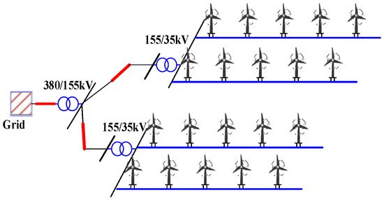
Figure 1.
Test wind farm system.
When the transient voltage dips and voltage swells events occur in the grid, the reactive power and transient voltage support need to be improved to suppress terminal voltage fluctuations of WTs. Due to the output active power and reactive power being limited by the WT power capacity, the active power of the WTs needs be reduced to achieve higher reactive power and voltage support. The active power of the WTs follows the maximum power capture command under normal operating conditions. When the output active power of the WT is reduced, the rotor speed is increased to achieve a balance between mechanical and electromagnetic power of the WT. The rotor speed of WTs will be increased and may even exceed the maximum rotor speed limit. Furthermore, the DC bus voltage is at risk of drastic fluctuations due to the accumulation of unbalanced power between the RSC and GSC of the WTs during the transient event.
In expansive wind farm clusters comprising numerous WTs, there is a significant interplay between injected power and voltage fluctuations among the different WTs. Due to the wake effects and differing spatial arrangements of the WTs, the wind speed and kinetic energy storage capacities of WTs are different. Hence, the transient reactive power and voltage support capacities of WTs are different. How to make full use of the kinetic energy storage capacities and regulate the output power of different WTs to realize the coordinated control of transient voltage in large-scale WFs is important.
2.2. Analysis of the Energy Flow Mechanism
When a deep transient voltage event occurs, the GSC current may exceed the limit because the GSC is required to output the same active power as the RSC. The unbalanced power from the RSC and GSC will build up on the DC bus, which leads to the DC bus voltage fluctuation. To reduce the unbalanced power, we should study the energy flow mechanism of the WT. The mechanical power of WT can be described as follows:
where ρ is the air density, R is the wind wheel radius, v is the wind speed, λ is the blade tip speed ratio, CP is the wind energy utilization factor, and β is the paddle pitch angle.
The electromagnetic power of the PMSG can be expressed as follows:
where Te is the electromagnetic power, ωr is the rotor speed.
The active and reactive power output to the grid can be described as follows:
The unbalanced power piled up at the DC bus can be expressed as follows:
where C is the DC bus capacitance and Vdc is the DC bus voltage.
The rotor energy storage control is used to reduce the unbalanced power ΔP in the proposed OTC scheme. The power ΔP2 is transformed into the kinetic energy storage of the rotor speed, which can be described separately as follows:
where R is the unloading resistance, and J is the rotational inertia.
Based on the above theoretical derivation, the overall energy flow of the WT can be expressed as follows:
Figure 2 shows the energy flow diagram of WT during the continuous FRT. The proposed OTC scheme reduces the unbalanced power ΔP of the WT to suppress the DC bus voltage fluctuations with the rotor energy storage and the chopper circuit.
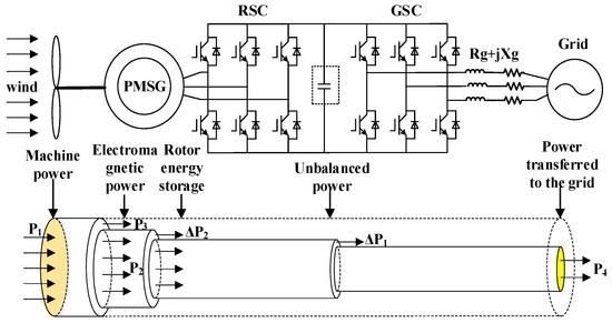
Figure 2.
Energy flow diagram of WT during the transient control.
2.3. Control Framework
Figure 3 shows the proposed framework for the optimized transient control (OTC) scheme. A two-level controller is established to achieve global transient control performance for WF. At the WF control level, the voltage sensitivity module is built to characterize the relationship between output power and terminal voltage of WTs. The WF central controller is developed to reduce the terminal voltage deviation by optimizing the output active and reactive power control reference of WTs.
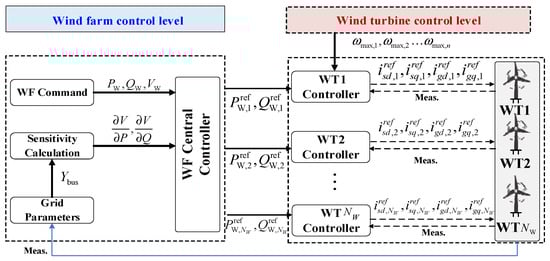
Figure 3.
Control frame of the OTC scheme.
At the WT control level, the converter operation stability range is considered to quantify the maximum KES of WTs. The output power and weak magnetic currents of the different WTs are optimally regulated to suppress the terminal voltage and the DC bus voltage fluctuations by fully utilizing the KES capability.
3. Power Optimization for Wind Farms
This section focuses on the problem of sudden voltage changes at the terminal voltage of different WTs. The output power of the WTs is regulated to minimize the voltage deviation during transient control periods.
3.1. Power Model of WF
The power regulation of the WTs can be described by a section of inertia links, as follows:
where is the number of WTs, and and are the output power time constants of the WTs.
Equation (8) can be linearized as follows:
Voltage sensitivity serves to define the correlation between the terminal voltage of wind turbines (WTs) and the power output levels within the system. The terminal voltage model for WTs is expressed in an incremental format,
where is the terminal voltage of the WTs, and and are the voltage sensitivities of the WTs.
The state space model of the WF can be expressed as follows:
Based on Equation (11), the discrete state-space model with sampling time can be derived from the continuous model as follows:
3.2. Objective Function and Constraints of Wind Farm Control Level
This controller is established to manage the power output of the WTs within the WF. The output power is regulated to track the maximum power tracking command under normal operating conditions. In addition, the output power is regulated to increase the reactive power and voltage support during the transient voltage control process. The optimization objective can be formulated as follows:
where , , and are the active power reference value and maximum power available of WT, is the maximum active power available of WF, is the voltage at the grid point, is the active power distribution coefficient, and are the transient voltage coefficients, and and are the weighting factors.
Under standard operational control, the active power reference of the WF adheres to the MPPT power command. The WF controller system assigns the optimal active power reference to each WT based on its respective available active power capacity. In the event of grid voltage dips or swells, the available active power capacity of each WT is adjusted in accordance with deviations in terminal voltage.
The aggregate active power from all WTs must match the WF’s total active power output requirement. The active and reactive power produced by each WT should not surpass its maximum available power limits. Therefore, these constraints can be formulated as follows:
where and are the reactive power reference value and maximum power available of WT.
4. Maximum Kinetic Energy Storage Control for the WTs
In this section, we examine the feasible operating region of the converter and the limitations imposed by SVPWM modulation ratios to precisely determine the maximum kinetic energy storage (KES) capability of the WTs. The d-q axis currents of the converter are optimized with the aim of minimizing voltage fluctuations on the DC bus and within the WTs, while simultaneously making full use of the KES capabilities of each WT.
4.1. Maximum KES Model
In this paper, the chopper circuit model is incorporated into the back-to-back converter configuration through the formulation of state-space equations and the transformation of the optimization problem using Model Predictive Control (MPC). This approach enables the regulation of WT voltage and current by optimizing the d-q axis current references. Utilizing the converter’s current transfer functions, the currents through the RSC and GSC can be represented as follows:
where and are the PI parameters, and , , and are the converter currents time constants of the WTs.
To deduce the predictive model of the RSC currents, Equation (16) can be written as follows:
Given that unbalanced power can induce fluctuations in the DC bus voltage, the relationship between the variation in DC bus voltage and the active power currents of the RSC and GSC can be formulated as follows:
where and are the output electromagnetic powers of the RSC and GSC, .
In Equation (18), can be traced back to the initial state-space matrix. However, includes a polynomial term of , which prevents it from being formulated as a quadratic programming problem. Therefore, by applying a Taylor series expansion around the operating point, the variation in can be approximated and linearized as follows:
The rotor kinetic energy can be effectively harnessed to mitigate unbalanced power during the continuous FRT process. According to the motion equation of the wind turbine WT, the dynamic behavior of the rotor’s mechanical speed, in relation to both mechanical and electromagnetic power [24], can be expressed as follows:
where is the kinetic energy storage, is the rotor speed of the WTs, is the mechanical power, and and are the mechanical and electromagnetic torque of the WTs.
As the electromagnetic torque decreases from to , the change in rotor kinetic energy during this interval can be described as follows:
where is the moment of inertia of the WTs.
Disregarding the impact of RSC differential currents, the terminal voltage of the PMSG can be formulated as follows:
where is the electrical angular frequency of the WTs, and , , are the stator resistance and inductance.
The feasible region of the RSC current is mainly limited by the converter capacity and DC modulation ratio in the SVPWM way, which can be defined as follows:
where is the maximum allowable current of the RSC, is the modulation ratio of the RSC, and and are the d-q axis voltages of the RSC.
Integrating Equations (22) and (23), the maximum rotor speed limit can be formulated as follows:
The increment of the maximum rotor speed limit can be expressed as follows:
Combining Equations (17)–(25), the continuous MPC-based state-space WT model with a relationship between the voltages and converter current reference can be expressed as follows:
Based on Equation (26), the discrete state-space model with sampling time can be derived from the continuous model as follows:
4.2. Objective Function and Constraints of Wind Turbine Control Level
This controller is designed to address the overvoltage issues of the DC bus and terminal voltage by maximizing the rotor kinetic energy storage capacities of different WTs. The cost functions are described as follows:
- (1)
- Objective 1: The primary goal is to regulate the DC bus voltage to maintain it within an acceptable range during the fault process. This can be expressed as follows:
- (2)
- Objective 2: The secondary goal is to regulate the d-axis current (also known as the weak magnetic current) of the RSC to maximize the KES capacity during the FRT and subsequent recovery process. This can be expressed as follows:
- (3)
- Objective 3: The third goal is to regulate the d-axis and q-axis currents of the Grid Side Converter (GSC) to adhere to the active and reactive power commands issued by the upper-level controller. This can be expressed as follows:
According to (29), (30) and (31), the cost function of the lower-level controller can be expressed by the following:
Based on the feasible region analysis of the RSC current, the constraints of the RSC currents can be quantified as follows:
Similarly, the control constraints of the GSC currents can be quantified as follows:
According to the grid code [25] on the continuous FRT time–voltage profile of grid-connected WTs, the magnitude and time of WT terminal voltage are subjected to the following constraints:
where is the start time of the low voltage process, and is start time of the high voltage process.
5. Case Study
5.1. Simulation Models
A D-PMSG-based GFM WF model is built in MATLAB (2022b)/Simulink to verify the effectiveness of the proposed OTC scheme, which is shown in Figure 1. The parameters of the WTs are shown in Table 1.

Table 1.
System parameters.
Figure 4 shows the point of common coupling voltage. In this simulation, the voltage dip starts at t = 2.0 s and lasts for 2.0 s. The voltage swell starts at t = 6.0 s and lasts for 10.0 s. The simulation time is 18.0 s. The wind speed of WT1~5 is shown in Figure 5.
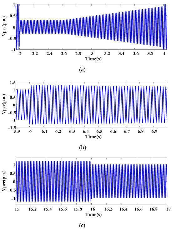
Figure 4.
Point of common coupling voltage (a). The voltage dips (b) The voltage swells start. (c) The voltage swells end.
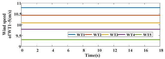
Figure 5.
Wind speed of WT1~5.
Figure 6 shows the control model with the proposed OTC scheme; the transient control is triggered in the period of t = 2 s~4 s, t = 6 s~16 s.
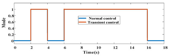
Figure 6.
Control mode of the proposed OTC scheme.
5.2. Control Performance with the Proposed Control and the Traditional Control Scheme
To demonstrate the effectiveness of the proposed OTC method, three different control methods were compared under the same conditions. Scheme 1 is the proposed OTCV scheme. In Scheme 2, the output power of WTs is optimized based on voltage sensitivity to improve the transient voltage support capabilities [24]. In Scheme 3, the output power of WTs is optimized based on the droop factor to reduce the transient voltage deviation [25].
Figure 7 shows the DC bus voltage of the WT with different control schemes. The DC bus voltage is a key transient stable parameter for WT operation. The DC bus voltage of the WT with the proposed scheme shows superiority compared to the other control schemes.
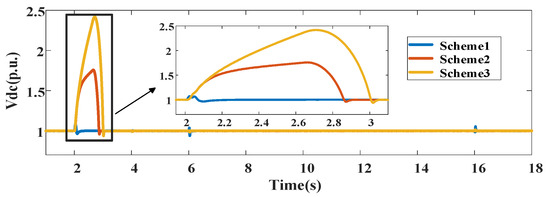
Figure 7.
DC bus voltage of WT1 with different schemes.
The reactive power and terminal voltage of WT1 with different control schemes are shown in Figure 8 and Figure 9. It is found that the proposed control scheme shows better performance during the continuous FRT than the traditional control schemes. The reactive power support capacity is efficiently improved, and the terminal voltage deviation is reduced by the proposed OTC scheme during the transient process.
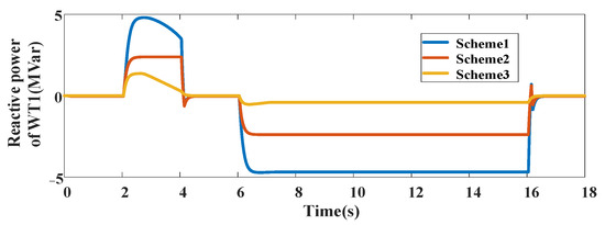
Figure 8.
Reactive power of WT1 with different schemes.
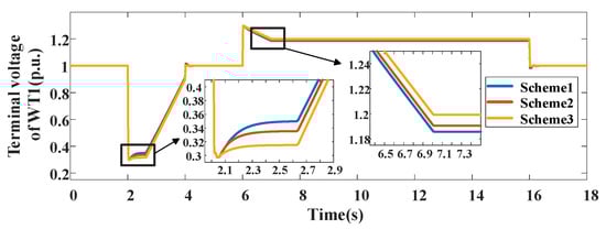
Figure 9.
Terminal voltage of WT1 with different schemes.
Table 2 illustrates the comparative results of the terminal voltage of the WT1 with three control schemes during the transient control process. During the severe voltage dip period, the terminal voltage deviation with the proposed scheme can be reduced by 6.36% and 12.50% compared to the traditional control schemes. During the severe voltage swell period, the terminal voltage deviation with the proposed scheme can be reduced by 1.00% and 1.50% compared to the traditional control schemes.
Table 2.
Terminal voltage of the WT1 with three control schemes.
Figure 10 and Figure 11 show the active power and rotor speed of the WT1 with different control schemes. As can be seen from Figure 11, the rotor speed shows superiority with the proposed control compared to the traditional control schemes. The rotor speed of the proposed OTC scheme is increased to reduce the wind energy losses and unbalanced power at the DC bus during the transient voltage period.
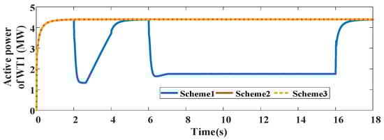
Figure 10.
Active power output of WT1 with different control schemes.
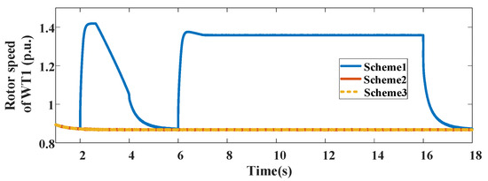
Figure 11.
Rotor speed of WT1 with different control schemes.
Table 3 illustrates the comparative results of the kinetic energy storage capacity of WT1 with the different control schemes. It can be seen that the maximum rotor energy storage with the proposed control scheme can be increased by 64.93% and 59.14% compared to the other control schemes under different transient control periods.
Table 3.
Comparative analysis of the KES of WT1 with the different control schemes.
The weak magnetic current and KES ratio of WT1 with different control schemes are shown in Figure 12 and Figure 13. As can be seen, the KES capacity of WT1 with the proposed control scheme shows better performance compared to the traditional control schemes. The weak magnetic current of WT1 is optimized to take full advantage of the KES capability during transient control periods.
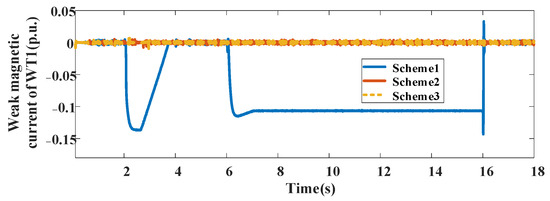
Figure 12.
Weak magnetic current of WT1 with different control schemes.
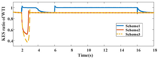
Figure 13.
KES ration of WT1 with different control schemes.
5.3. Control Performance Under Different Wind Speed Conditions
The wind speed fluctuations can affect the steady-state operation and transient stability of WTs and the whole WF. To demonstrate the robustness of the proposed OTC method, different wind speed conditions are considered in the following simulations. Figure 14 shows the different wind speed conditions under Case 1 (C1) and Case 2 (C2).
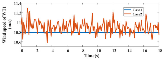
Figure 14.
Different wind speeds condition of WT1.
The DC bus voltage and terminal voltage of WT1 under different wind speed conditions are shown in Figure 15 and Figure 16. It is found that the proposed OTC scheme shows better transient voltage suppression performance than the traditional control scheme under different wind speed conditions. Figure 17 shows the rotor speed of WT1 under different wind speed conditions. The KES capability of WT1 with the proposed OTC scheme is increased to achieve better transient voltage support and reduce the wind energy losses under different wind speeds.
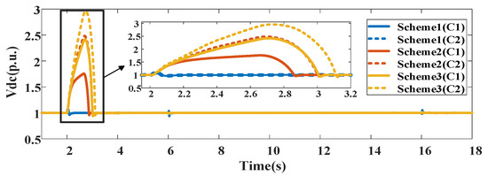
Figure 15.
DC bus voltage of WT1 under different wind speed conditions.
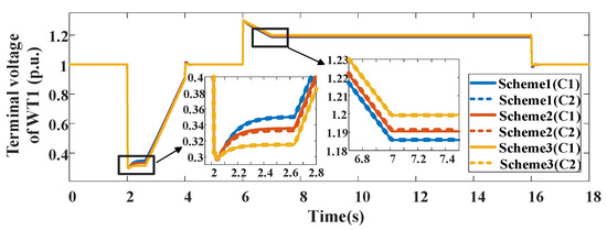
Figure 16.
Terminal voltage of WT1 under different wind speed conditions.
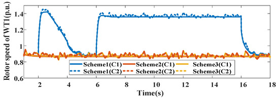
Figure 17.
Rotor speed of WT1 under different wind speed conditions.
6. Conclusions
In this paper, an OCT scheme is proposed to improve the transient stability of GFM WF based on the transient stability of the WTs. The converter’s current operating safety range is considered to quantify the maximum KES capabilities of the WTs. AT the WF control level, the global transient voltage control problem is solved by optimizing the output reactive power of different WTs of the WF. At the WT control level, the KES capacity is maximized by regulating the active power and the weak magnetic current, and the transient voltage support is efficiently enhanced by making full use of the KES capacity of WT. The simulation results show that the terminal voltage mitigation of the WTs can be reduced by 6.36% and 12.50% with the proposed scheme compared with the traditional control schemes during the transient control periods. And the maximum of rotor energy storage with the proposed can be increased by 64.93% and 59.14% compared to the other control schemes under different transient control periods. The transient stability of large-scale WFs is effectively improved with the proposed OCT scheme. Especially when the grid voltage swells to 120%, the terminal voltage deviation of the WT can be decreased by 12.50% compared to that with the traditional control scheme.
Author Contributions
Conceptualization, P.H.; methodology, D.L.; formal analysis, K.C.; data curation, L.W. All authors have read and agreed to the published version of the manuscript.
Funding
This work was supported in part by the National Key R&D Program of China (2023YFB2406600) and in part by the National Natural Science Foundation of China (52207050).
Institutional Review Board Statement
Not applicable.
Informed Consent Statement
There are no human subjects in this article and informed consent is not applicable.
Data Availability Statement
Data are contained within the article.
Conflicts of Interest
The authors declare that they have no known competing financial interests or personal relationships that could have appeared to influence the work reported in this paper.
References
- Gul, W.; Gao, Q.; Lenwari, W. Optimal Design of a 5-MW Double-Stator Single-Rotor PMSG for Offshore Direct Drive Wind Turbines. IEEE Trans. Ind. Appl. 2020, 56, 216–225. [Google Scholar] [CrossRef]
- Singh, B.; Niwas, R. Power Quality Improvement of PMSG-Based DG Set Feeding Three-Phase Loads. IEEE Trans. Ind. Appl. 2016, 52, 466–471. [Google Scholar] [CrossRef]
- Zeng, L.; Li, C.; Li, Z.; Shahidehpour, M.; Zhou, B.; Zhou, Q. Hierarchical Bipartite Graph Matching Method for Transactive V2V Power Exchange in Distribution Power System. IEEE Trans. Smart Grid 2020, 12, 301–311. [Google Scholar] [CrossRef]
- Huang, S.; Wu, Q.; Liao, W.; Wu, G.; Li, X.; Wei, J. Adaptive Droop-Based Hierarchical Optimal Voltage Control Scheme for VSC-HVdc Connected Offshore Wind Farm. IEEE Trans. Ind. Inform. 2021, 17, 8165–8176. [Google Scholar] [CrossRef]
- Li, W.; Zhu, M.; Chao, P.; Liang, X.; Xu, D. Enhanced FRT and Postfault Recovery Control for MMC-HVDC Connected Offshore Wind Farms. IEEE Trans. Power Syst. 2020, 35, 1606–1617. [Google Scholar] [CrossRef]
- Xu, D.; Wu, Q.; Zhou, B.; Li, C.; Bai, L.; Huang, S. Distributed Multi-Energy Operation of Coupled Electricity, Heating, and Natural Gas Networks. IEEE Trans. Sustain. Energy 2020, 11, 2457–2469. [Google Scholar] [CrossRef]
- Huang, S.; Wu, Q.; Guo, Y.; Chen, X.; Zhou, B.; Li, C. Distributed Voltage Control Based on ADMMfor Large-Scale Wind Farm Cluster Connected to, V.S.C.-H.V.D.C. IEEE Trans. Sustain. Energy 2020, 11, 584–594. [Google Scholar] [CrossRef]
- Ruan, J.-Y.; Lu, Z.-X.; Qiao, Y.; Min, Y. Analysis on Applicability Problems of the Aggregation-Based Representation of Wind Farms Considering DFIGs’ LVRT Behaviors. IEEE Trans. Power Syst. 2016, 31, 4953–4965. [Google Scholar] [CrossRef]
- Jin, R.; Hou, P.; Yang, G.; Qi, Y.; Chen, C.; Chen, Z. Cable routing optimization for offshore wind power plants via wind scenarios considering power loss cost model. Appl. Energy 2019, 254, 113719. [Google Scholar] [CrossRef]
- Shi, M.; Chen, X.; Zhou, J.; Chen, Y.; Wen, J.; He, H. Advanced Secondary Voltage Recovery Control for Multiple HESSs in a Droop-Controlled DC Microgrid. IEEE Trans. Smart Grid 2019, 10, 3828–3839. [Google Scholar] [CrossRef]
- Dash, P.; Patnaik, R.; Mishra, S. Adaptive fractional integral terminal sliding mode power control of UPFC in DFIG wind farm penetrated multimachine power system. Prot. Control Mod. Power Syst. 2018, 3, 8. [Google Scholar] [CrossRef]
- Raza, M.; Collados, C.; Gomis-Bellmunt, O. Reactive power management in an offshore AC network having multiple voltage source converters. Appl. Energy 2017, 265, 793–803. [Google Scholar] [CrossRef]
- Xiao, X.-Y.; Yang, R.-H.; Zheng, Z.-X.; Wang, Y. Cooperative Rotor-Side SMES and Transient Control for Improving the LVRT Capability of Grid-Connected DFIG-Based Wind Farm. IEEE Trans. Appl. Supercond. 2019, 29, 1–5. [Google Scholar] [CrossRef]
- Zou, Z.-C.; Liao, J.-C.; Lei, Y.; Mu, Z.-L.; Xiao, X.-Y. Postfault LVRT Performance Enhancement of DFIG Using a Stage-Controlled SSFCL-RSDR. IEEE Trans. Appl. Supercond. 2019, 29, 1–6. [Google Scholar] [CrossRef]
- Ren, J.; Xiao, X.; Zheng, Z.; Ma, Z. ASMES-Based Dynamic Current Limiter to Improve the LVRTCapability of DFIG-Based, W.E.C.S. IEEE Trans. Appl. Supercond. 2021, 31, 1–5. [Google Scholar]
- Guo, W.; Zhang, G.; Zhang, J.; Song, N.; Gao, Z.; Xu Xi Jing, L.; Teng, Y.; Zhu, Z.; Xiao, L. Development of a 1-MVA/1-MJ Superconducting Fault Current Limiter–Magnetic Energy Storage System for LVRT Capability Enhancement and Wind Power Smoothing. IEEE Trans. Appl. Supercond. 2018, 28, 1–5. [Google Scholar] [CrossRef]
- Alsmadi, Y.M.; Xu, L.; Blaabjerg, F.; Ortega, A.J.P.; Abdelaziz, A.Y.; Wang, A.; Albataineh, Z. Detailed Investigation and Performance Improvement of the Dynamic Behavior of Grid-Connected DFIG-Based Wind Turbines Under LVRT Conditions. IEEE Trans. Ind. Appl. 2018, 54, 4795–4812. [Google Scholar] [CrossRef]
- Zhou, H.; Yao, W.; Sun, K.; Zong, Q.; Zhao, H.; Wen, J. Enhancing Fault Ride-Through and Voltage Support Capability for MMC-HVDC Integrated Offshore Wind Farms Based on Multi-Mode Matching. IEEE Trans. Sustain. Energy 2024, 15, 1256–1268. [Google Scholar] [CrossRef]
- Jia, K.; Dong, X.; Wen, Z.; Wu, W.; Bi, T. Harmonic Injection Based Fault Ride-through Control of MMC-HVDC Connected Offshore Wind Farms. IEEE Trans. Sustain. Energy 2023, 14, 1796–1806. [Google Scholar] [CrossRef]
- Zhou, C.; Wang, Z.; Xin, H.; Ju, P. A PQ Coordination Based Model Predictive Control for DFIG High-Voltage Ride Through. IEEE Trans. Energy Convers. 2022, 37, 254–263. [Google Scholar] [CrossRef]
- Bao, W.; Wu, Q.; Ding, L.; Huang, S.; Terzija, V. A Hierarchical Inertial Control Scheme for Multiple Wind Farms with BESSs Based on ADMM. IEEE Trans. Sustain. Energy 2021, 12, 751–760. [Google Scholar] [CrossRef]
- Xiong, Y.; Yao, W.; Yao, Y.; Fang, J.; Ai, X.; Wen, J.; Cheng, S. Distributed Cooperative Control of Offshore Wind Farms Integrated via MTDC System for Fast Frequency Support. IEEE Trans. Ind. Electron. 2023, 70, 4693–4704. [Google Scholar] [CrossRef]
- Lyu, X.; Jia, Y.; Xu, Z. A Novel Control Strategy for Wind Farm Active Power Regulation Considering Wake Interaction. IEEE Trans. Sustain. Energy 2020, 11, 618–628. [Google Scholar] [CrossRef]
- Guo, Y.; Gao, H.; Wu, Q.; Zhao, H.; Ostergaard, J.; Shahidehpour, M. Enhanced voltage control ofVSC-HVDC-connected offshorewind farms based on model predictive control. IEEE Trans. Sustain. Energy 2018, 9, 474–487. [Google Scholar] [CrossRef]
- Li, Y.; Xu, Z.; Zhang, J.; Meng, K. Variable droop voltage control for wind farm. IEEE Trans. Sustain. Energy 2018, 9, 491–493. [Google Scholar] [CrossRef]
Disclaimer/Publisher’s Note: The statements, opinions and data contained in all publications are solely those of the individual author(s) and contributor(s) and not of MDPI and/or the editor(s). MDPI and/or the editor(s) disclaim responsibility for any injury to people or property resulting from any ideas, methods, instructions or products referred to in the content. |
© 2025 by the authors. Licensee MDPI, Basel, Switzerland. This article is an open access article distributed under the terms and conditions of the Creative Commons Attribution (CC BY) license (https://creativecommons.org/licenses/by/4.0/).