Abstract
In this study, the thickness of a thin film (tc) at a low primary electron energy of less than or equal to 10 keV was calculated using electron energy-loss spectroscopy. This method uses the ratio of the intensity of the transmitted background spectrum to the intensity of the transmission electrons with zero-loss energy (elastic) in the presence of an accurate average inelastic free path length (λ). The Monte Carlo model was used to simulate the interaction between the electron beam and the tested thin films. The total background of the transmitted electrons is considered to be the electron transmitting the film with an energy above 50 eV to eliminate the effect of the secondary electrons. The method was used at low primary electron energy to measure the thickness (t) of C, Si, Cr, Cu, Ag, and Au films below 12 nm. For the C and Si films, the accuracy of the thickness calculation increased as the energy of the primary electrons and thickness of the film increased. However, for heavy elements, the accuracy of the film thickness calculations increased as the primary electron energy increased and the film thickness decreased. High accuracy (with 2% uncertainty) in the measurement of C and Si thin films was observed at large thicknesses and 10 keV, where . However, in the case of heavy-element films, the highest accuracy (with an uncertainty below 8%) was found for thin thicknesses and 10 keV, where . The present results show that an accurate film thickness measurement can be obtained at primary electron energy equal to or less than 10 keV and a ratio of . This method demonstrates the potential of low-loss electron energy-loss spectroscopy in transmission electron microscopy as a fast and straightforward method for determining the thin-film thickness of the material under investigation at low primary electron energies.
1. Introduction
Accurate wafer-thickness measurements are essential to ensure the quality of semiconductor devices [1,2]. This requires non-destructive analysis methods. Conventional techniques such as profilometry and ellipsometry have limitations in terms of resolution, sensitivity, and sample preparation requirements [3]. Electron Probe Microanalysis (EPMA) is a non-destructive method for collecting characteristic X-rays from a monolayer thin film deposited on a bulk substrate after bombarding it with a fixed energetic electron beam [4,5,6,7]. Different relative intensities of the film and substrate were generated by varying the film thickness. These characteristic X-ray intensities from the film and substrate were compared with those from the bulk standards, defining a quantity called the k-ratio. This method assumes that a sample has a well-known and homogenous chemical composition.
Electron energy-loss spectroscopy (EELS) is widely and effectively used to measure the sample thickness [8,9,10,11,12] at high primary electron energies. EELS is an analysis of the energy distribution of a monoenergetic electron beam passing through the thin film of a material [8]. It is well known that the shape of the background in electron energy spectra varies according to the atomic number, making it a valuable tool for material characterization [13]. The energy resolution is usually 1 eV, but if a monochromatic electron beam is used, it can reach 0.1 eV [14]. This can be achieved if the incident electron beam energy is sufficiently high, and the sample is sufficiently thin. Consequently, most of the incident electrons passed through the sample after interacting with the sample atoms and lost some of their energy. Different materials and different material structures absorb different amounts of energy. Therefore, the spectrometer can analyze the energy spectrum generated by the transmission electron and obtain both identification and structural information about the samples.
In general, to apply the EELS technique, the thickness should be less than the mean free path for inelastic scattering if quantification is attempted [15]. Furthermore, the approach commonly used in transmission electron microscopy (TEM) may not work at such low primary beam voltages [16]. This is because the method used requires a low level of multiple scattering, which is indicated by the presence of secondary electrons.
The study of surface thin films and the determination of thickness using overlayer techniques are widely used in Auger Electron Spectroscopy (AES) and X-ray Photoelectron Spectroscopy (XPS) [17]. For example, in Energy Dispersive X-ray Spectroscopy (EDS) analysis, the thickness is used to determine whether absorption and/or fluorescence corrections are required and, if so, the magnitude of the corrections. The specimen thickness can provide an estimate of the beam broadening to determine the spatial resolution of X-ray analysis [15].
EELS can also provide an approximate value of the sample thickness (t) for both the crystalline and amorphous specimens by simply integrating the EELS spectra [18,19]. The log-ratio method of the specimen thickness (t) to the mean free path (λ) for inelastic scattering of the material is given by the following [15]:
where Ie is the integrated intensity of the zero-loss energy peak (elastic peak) and It is the total integrated intensity of the spectrum background. To obtain an accurate measurement of film thickness, the inelastic mean free path (λ) must be known. Hence, Equation (1) can be directly used to measure the sample thickness, as follows:
Equation (2) is independent of the collection angle. To obtain accurate experimental results from Equation (2), the spectrum should be collected for all scattering angles [18]. Leapman et al. [18] reported that Equation (1) is used for high primary energies and is valid up to a thickness (t) five times the inelastic mean free path. Malis et al. [15] and Joy et al. [19] also reported that Equation (1) should be used at high energies, a wide collection angle, and a ratio of t/λ~4 to obtain accurate film thickness measurements. Several studies have demonstrated the validity of Equation (2) at high electron beam energies in the tens of keV range [15,18,19,20].
Malis et al. [15] also used Equation (1) to measure λ. They reported that the precision of their data was between 10 and 20% for primary electron energies above 100 keV. However, Jaber et al. [21] also used Equation (1) to measure λ at primary electron energies below 5 keV and the total integrated intensity of the spectrum background above 50 eV. The uncertainty of the results was approximately 5% of the experimental data obtained by Tanuma et al. [22].
From the above discussion, the present study has used Equation (2) to theoretically measure the thin-film thickness of C, Si (as light material), Cr, Cu, Ag, and Au (as heavy materials) between 2 and 12 nm at normal incidence electrons with low energies of 1, 3, 5, 7.5, and 10 keV. The challenge of the present study was to use the log-ratio method (Equation (2)) at primary electron energy is equal to or less than 10 keV, and to calculate the thin-film thickness with high accuracy at different ratios of t/λ [15,18]. The Monte Carlo computational method [23] was used to simulate the transmitted electron energy spectra of freestanding films. The inelastic mean free path length (λ) values were obtained from the input data of the Geant-4 Monte Carlo model [23]. The model calculates λ using Ashely’s approach [20]. The uncertainty in the inelastic mean free path length was less than 5% for light elements and increased for heavy elements [24].
2. Monte Carlo Simulations
When the electron beam passes through a thin-film sample, the electrons are subject to various interactions, including elastic and inelastic scattering. Monte Carlo (MC) simulation is a powerful method for modeling the behavior of particles in various physical systems, including electron–solid interactions [21,22,23,25,26]. Some software packages have been specifically developed for this purpose, such as Geant4 [27] and Monte Carlo N-Particle Transport Codes (MCNP) [28]. These packages provide libraries and tools for defining complex material geometries, specifying interaction physics, and performing detailed particle transport and interaction simulations.
The present study used the Geant4 Monte Carlo program developed by Kieft and Bosch [23,27]. The program calculates elastic scattering using Mott cross-section data [29,30]. The program also uses discrete inelastic losses of inelastic scattering [31], where each energy loss is used to produce secondary electrons (SE) with the same energy as that lost by the original electron (usually primary electrons (PE)) and possibly by other secondary electrons (SE). The inelastic loss was determined from dielectric function data [31]. Consequently, the MC model does not include losses caused by surface plasmons. All electrons transmitted from the film were used to obtain the transmitted electron spectrum. These include the secondary electrons, Auger peaks, plasmon peaks, and elastic (zero-loss energy) peaks [32,33]. Secondary electrons are excited electrons whose energy is defined as less than 50 eV in all of the excited electrons produced from the constituent atoms of a sample by inelastic scattering of the incident electrons (primary electrons) in the sample [32,33,34]. The escape depth of secondary electrons from the sample was as small as 5–10 nm for most metals. Auger electrons are the result of the excitation of core-level electrons [32,33]. The vacancy is filled by a higher-energy electron in the outer shell, and the excess energy can be used to eject another electron, the Auger electron. Auger electrons help to identify elements in complex materials that have many peaks in the collected electron spectrum. In addition, the inelastic scattering of electrons in the outer shell is visible as plasmon peak(s) in the EELS spectral range of 2–50 eV, which is close to the zero-loss energy peak (elastic peak) [32,33]. The zero-loss energy peak (elastic peak) is that performed by the incident electrons which are scattered elastically by the atomic nucleus and transmitted from the sample without energy loss [32,33].
3. Results and Discussions
Figure 1 and Figure 2 show the energy loss spectra of Si and Au with different thicknesses, respectively, at different primary electron energies (1, 5, and 10 keV). The zero-loss energy peak clearly has a maximum value at a 2 nm film thickness and decreases with increasing thickness. As the thickness increases, the probability of plural scattering becomes more significant, causing the spectral shape to deviate from the single scattering distribution and the intensity of the zero-loss energy peak to become smaller [18]. Furthermore, the peak increases as the primary electron energy increases (i.e., 10 keV). This behavior was due to the increased mean free path length of the primary electrons. In addition, primary electrons with higher energies inside a low-atomic-number material (e.g., C and Si) are subject to less inelastic scattering [32,33]. Consequently, the volume of the primary electron–thin film interaction within the sample decreases as the energy increases or the thickness decreases. This allowed most of the primary electrons to be transmitted from the film at high energies (e.g., 10 keV). The intensity of the zero-loss energy peak decreased as the film thickness increased. This is to be expected, as thicker films (in terms of primary electron energy (e.g., t = 10 nm at 3 keV)) cause primary electrons to lose energy owing to more inelastic scattering with film atoms. This results in an increase in the number of electrons in the transmitted electron background spectrum with an energy lower than the primary energy. This is illustrated in Figure 1B,C, where the plasmon electron peak increases with the film thickness. The plasmon peak was superimposed on the transmitted electron background spectrum.
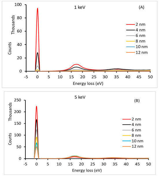
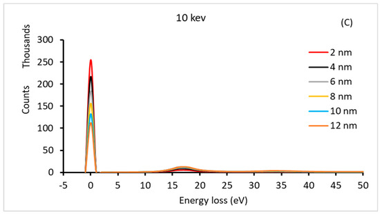
Figure 1.
The energy-loss spectrum of different Si thin-film thicknesses at different primary electron energies: (A) 1 keV, (B) 5 keV, and (C) 10 keV.
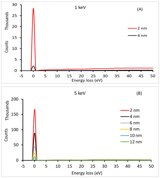
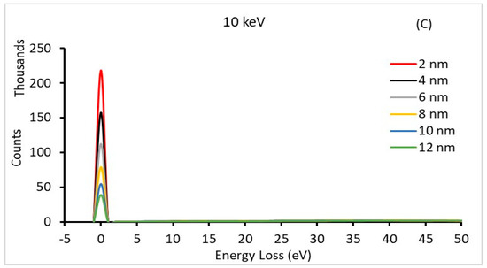
Figure 2.
The energy-loss spectrum of different Au thin-film thicknesses at different primary electron energies: (A) 1 keV, (B) 5 keV, and (C) 10 keV.
Equation (2) was used to calculate the thicknesses of the C, Si, Cr, Cu, Ag, and Au films. To ensure that the total transmitted electron intensity (It) is due to the primary electron, in the present work, the effect of the secondary electrons on the results is minimized by collecting the transmitted electrons with energies greater than 50 eV. This is because of the nature of the secondary electrons, which have no general tendency toward the energy of the incident electrons, and the thickness of the film [32,33,34]
Table 1, Table 2, Table 3, Table 4, Table 5 and Table 6 show the calculated thin-film thicknesses of C, Si, Cr, Cu, Ag, and Au, respectively. The missing data in the tables are due to the number of zero-loss energy electrons (Ie), which is considered to be zero compared with the large number of electrons in the transmitted electron background (It). In general, the accuracy of the calculated tc increased with an increase in the primary electron energy. The results show that the t/λ ratio decreases as the primary electron energy increases and the percentage error decreases. The lowest percentage error was found for light elements (C and Si) at 10 keV primary electron energy and a large sample thickness, where t/λ~1. However, the highest percentage error of approximately 22% was found for Au at 3 keV and a large sample thickness, where t/λ ≈ 4.5.

Table 1.
The calculated C thin-film thickness in nm as a function of primary electron energy (keV) using Equation (2).

Table 2.
The calculated Si thin-film thickness in nm as a function of primary electron energy (keV) using Equation (2).

Table 3.
The calculated Cr thin-film thickness in nm as a function of primary electron energy (keV) using Equation (2).

Table 4.
The calculated Cu thin-film thickness in nm as a function of primary electron energy (keV) using Equation (2).

Table 5.
The calculated Ag thin-film thickness in nm as a function of primary electron energy (keV) using Equation (2).

Table 6.
The calculated Au thin-film thickness in nm as a function of primary electron energy (keV) using Equation (2).
To understand the results for the light elements, the calculation for the Si thin film was investigated (Table 2 and Figure 3). The percentage error in tc is approximately 5% at 1 keV for a thickness of 2 nm and increases to 10% for a film thickness of 12 nm. By investigating the ratio t/λ, it can be observed that the ratio increases with increasing film thickness. t/λ = 1.06 to 6.39 for 2 nm and 12 nm, respectively. The latter is inconsistent with the assumption introduced in the literature [15,18] that t/λ should not be greater than 5. This is reflected in the percentage error of tc, which was approximately 10%. This can be explained by the fact that the primary electron range is small; therefore, most of the electron–solid interaction volume is covered by the sample [13,35]. This implies that the primary electrons are subjected to more inelastic scattering events. Therefore, the number (intensity) of transmitted electrons of the zero-loss energy is considered to be small compared to the total number of electrons transmitted. Therefore, the percentage error increases to approximately 10%. However, at a thickness of 2 nm, the percentage error is 5%. This is because of the interaction volume of the primary electrons and the sample atoms that are not covered by the sample. Therefore, more electrons can transmit through the sample without energy loss after low elastic scattering events. At 10 keV, the inelastic mean free path length is 12.39 nm, which is larger than the tested Si thickness (12 nm). This was reflected in the calculated thickness (tc), with a percentage error of less than 3% at a thickness of 2 nm, where t/λ < 1. For primary electron energies of 3, 5, and 7.5 keV, where λ = 4.58 nm, 6.97 nm, and 9.81 nm, respectively, the calculated tc had a maximum percentage error of 5%. In general, the percentage error decreases as the tc/λ ratio increases. These results show that the thin-film calculation using Equation (2) for light elements can be conducted by low-energy primary electrons with a low percentage error below 5% for primary electrons above 1 keV.
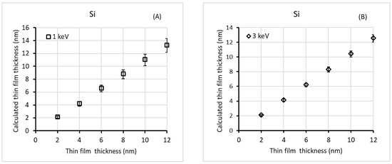
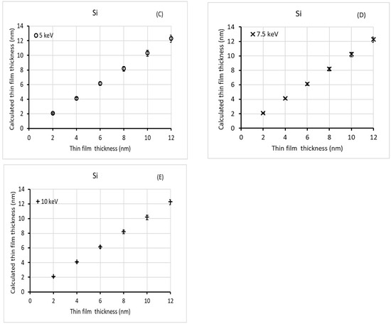
Figure 3.
The calculated C thin-film thickness versus the accepted thickness value in (nm) at different primary electron energies (A) 1 keV, (B) 3 keV, (C) 5 keV, (D) 7.5 keV, and (E) 10 keV.
For the heavy elements, the film thicknesses obtained from the Cr, Cu, Ag, and Au samples are shown in Table 3, Table 4, Table 5 and Table 6 m, respectively. The maximum percentage error was found for Au film thicknesses greater than 6 nm at 3 keV (Table 6 and Figure 4B). This can be explained by the increase in the number of inelastic scattering events that the primary electron could experience before being transmitted. As the primary electron energy increases, the number of inelastic scattering events decreases, and the number of elastic scattering events increases. Therefore, the number (intensity) of electrons with zero loss energy increases. In general, the percentage error of the calculated film thickness decreases as the primary electron energy increases and the film thickness decreases. For Au, which is considered as a heavy element, as shown in Table 6 and Figure 4, the lower percentage error (around 8%) was found at a 2 nm film thickness and 10 keV, where λ = 6.86 nm and . As the thin-film tc increases, the percentage error increases as the ratio of t/λ increases. This observation is contrary to that observed for Si. The influence of the elastic peak increased with heavy elements (e.g., Au). This keeps the primary electrons close to the bombarded surface. Therefore, a few electrons with zero-loss energy were transmitted from the sample, and more primary electrons became part of the spectrum background. As a result, the ratio of transmitted to background electrons decreases. This was reflected in the accuracy of the film thickness measurements at t ≥ λ. It is known that the measured data for the inelastic mean free path length of Au at high energies are overestimated by more than 10% [22,35]. Therefore, the use of the λ values of Au presented in Equation (2) reflects the film thickness calculation. The percentage error in the film thickness calculation at high primary electron energies (e.g., 10 keV and t > 8 nm) was approximately 10%.
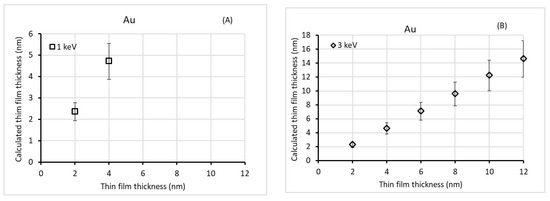
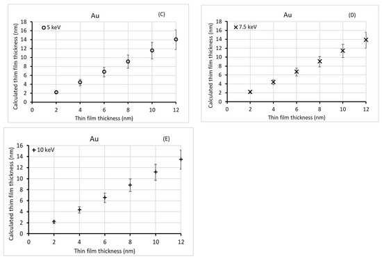
Figure 4.
The accepted thickness values in (nm) at different primary electron energies: (A) 1 keV, (B) 3 keV, (C) 5 keV, (D) 7.5 keV, and (E) 10 keV.
The present results show that an accurate thin-film thickness measurement can be conducted using the log-ratio method (Equation (2), with a percentage error below 5% at low primary electron energies as for light elements. The difference between the present study’s data and those published by Malis et al. [15], Joy et al. [19], and Leapman et al. [18] is due to the narrower collection angle of the transmitted electrons and the low accuracy of the inelastic mean free path length used in their calculations. The uncertainty in the inelastic mean free path length has been reported to be approximately 30% [15,18,24]. For example, the percentage error in the results of a study by Malis et al. [15] was reported to be approximately 20% in the range of primary energy between 20–120 keV and for thick samples with thicknesses greater than 80 nm. In addition, the influence of elastic scattering on the intensity of zero-loss energy peaks causes the traversed path length to exceed that of a straight-line path [23]. Therefore, to increase the accuracy of the film thickness measurement, a wide collection angle should be set up to collect all transmitted electrons experimentally. In addition, an accurate inelastic mean free path length should be used.
4. Conclusions
EELS is a direct and powerful analytical technique for measuring sample thickness at high primary electron energies [15,18,24]. In this study, the log-ratio method proposed by Joy et al. [19] was used to calculate the thin-film thickness at low primary electron energies. To obtain accurate film thickness measurements, the inelastic mean free path, λ, must be known. Transmitted electron spectra from thin films (2, 4, 6, 8, 10, and 12 nm) were simulated for C, Si, Cr, Cu, Ag, and Au at primary beam energies equal to or less than 10 keV. The total transmitted electron background is considered to be the electrons that have transmitted the film with energy above 50 eV to eliminate the effect of the secondary electrons. High accuracy in thin-film calculations was found in the present study. For light elements (C and Si), the high accuracy in the calculation of thin films was found at 10 keV and a large sample thickness, where . The percentage error was less than 5%. However, the maximum percentage error of 10% was found at 1 keV and large sample thickness and . For the heavy element (Cr, Cu, Ag, and Au) films, the highest accuracy (with a percentage error of approximately 8%) was found at high primary electron energies and thin-film thickness, where is less than or equal to 2.
The current findings indicate that the EELS method can provide precise film thickness measurements at low primary electron energies as at high energies, as long as the ratio of t/λ is equal to or less than 2.
Further experimental work is required to evaluate the use of the EELS method presented in this study. The study of photon absorption in single and double layers can be used in the future to evaluate the present findings.
Author Contributions
Methodology, A.M.D.J. and Software, A.M.D.J. and Formal analysis, A.M.D.J., A.A., S.R.A.-B.; Data collection, S.R.A.-B.; Writing—original draft, A.M.D.J. and A.A.; Review & editing, A.M.D.J., M.S.M., H.A.D., V.H., D.S. and T.T. All authors have read and agreed to the published version of the manuscript.
Funding
The Czech Nano Lab project LM2023051 funded by MEYS CR.
Institutional Review Board Statement
The study was conducted in accordance with the Declaration of Helsinki, and approved by the Institutional Review Board (or Ethics Committee) of Aqaba Medical Sciences University-Aqaba (77110)-Jordan.
Informed Consent Statement
Not applicable.
Data Availability Statement
Data are contained within the article.
Acknowledgments
We acknowledge the Internal Grant Agency of Brno University of Technology (Grant No. 6FEKT-S-23-8228) for providing the laboratory infrastructure.
Conflicts of Interest
The authors declare no conflict of interest.
References
- Biebl, F.; Glawar, R.; Jalali, A.; Ansari, F.; Haslhofer, B.; de Boer, P.; Sihn, W. A conceptual model to enable prescriptive maintenance for etching equipment in semiconductor manufacturing. Procedia CIRP 2020, 88, 64–69. [Google Scholar] [CrossRef]
- Weber, A. Smart manufacturing in the semiconductor industry: An evolving nexus of business drivers, technologies, and standards. In Smart Manufacturing; Elsevier: New York, NY, USA, 2020; pp. 59–105. [Google Scholar] [CrossRef]
- Huang, H.-T.; Terry, F.L., Jr. Spectroscopic ellipsometry and reflectometry from gratings (Scatterometry) for critical dimension measurement and in situ, real-time process monitoring. Thin Solid Films 2004, 455–456, 828–836. [Google Scholar] [CrossRef]
- Llovet, X.; Moy, A.; Pinard, P.T.; Fournelle, J.H. Electron probe microanalysis: A review of recent developments and applications in materials science and engineering. Prog. Mater. Sci. 2021, 116, 100673. [Google Scholar] [CrossRef]
- Terborg, R.; Kim, K.J.; Hodoroaba, V.-D. Determination of Thin Film Thickness and Composition using Energy Dispersive EPMA. Microsc. Microanal. 2022, 28, 672–673. [Google Scholar] [CrossRef]
- Terborg, R.; Kim, K.J.; Hodoroaba, V. Elemental composition and thickness determination of thin films by electron probe microanalysis. Surf. Interface Anal. 2023, 55, 496–500. [Google Scholar] [CrossRef]
- Sokolov, S.A.; Milovanov, R.A.; Sidorov, L.N. Determination of the Thickness of Thin Films Based on Scanning Electron Microscopy and Energy Dispersive X-Ray Analysis. J. Surf. Investig. 2019, 13, 836–847. [Google Scholar] [CrossRef]
- Egerton, R.F. Electron Energy-Loss Spectroscopy in the Electron Microscope; Springer US: Boston, MA, USA, 2011. [Google Scholar] [CrossRef]
- Egerton, R.F.; Cheng, S.C. Measurement of local thickness by electron energy-loss spectroscopy. Ultramicroscopy 1987, 21, 231–244. [Google Scholar] [CrossRef]
- Niedrig, H. Film-thickness Determination in Electron Microscopy: The Electron Backscattering Method. Opt. Acta 1977, 24, 679–691. [Google Scholar] [CrossRef]
- Egerton, R.F.; Malac, M. EELS in the TEM. J. Electron. Spectros. Relat. Phenom. 2005, 143, 43–50. [Google Scholar] [CrossRef]
- Stephens, A.P. Quantitative microanalysis by electron energy-loss spectroscopy: Two corrections. Ultramicroscopy 1980, 5, 343–349. [Google Scholar] [CrossRef]
- Assa’d, A.M.D. Monte Carlo computation of the influence of carbon contamination layer on the energy distribution of backscattered electrons emerging from Al and Au. Jordan J. Phys. 2019, 12, 37–44. [Google Scholar]
- Egerton, R.F. Electron energy-loss spectroscopy in the TEM. Rep. Prog. Phys. 2009, 72, 016502. [Google Scholar] [CrossRef]
- Malis, T.; Cheng, S.C.; Egerton, R.F. EELS log-ratio technique for specimen-thickness measurement in the TEM. J. Electron. Microsc. Tech. 1988, 8, 193–200. [Google Scholar] [CrossRef] [PubMed]
- Botton, G.A.; L’espérance, G.; Gallerneault, C.E.; Ball, M.D. Volume fraction measurement of dispersoids in a thin foil by parallel energy-loss spectroscopy: Development and assessment of the technique. J. Microsc. 1995, 180, 217–229. [Google Scholar] [CrossRef]
- Haasch, R.T. X-Ray Photoelectron Spectroscopy (XPS) and Auger Electron Spectroscopy (AES). In Practical Materials Characterization; Springer: New York, NY, USA, 2014; pp. 93–132. [Google Scholar] [CrossRef]
- Leapman, R.D.; Fiori, C.E.; Swyt, C.R. Mass thickness determination by electron energy loss for quantitative X-ray microanalysis in biology. J. Microsc. 1984, 133, 239–253. [Google Scholar] [CrossRef] [PubMed]
- Joy, D.C.; Egerton, R.F.; Maher, D.M. Progress in the quantitation of EELS. In Scanning Electron Microscopy; SEM: Washington, DC, USA, 1979; Volume 2, pp. 817–826. [Google Scholar]
- Iakoubovskii, K.; Mitsuishi, K.; Nakayama, Y.; Furuya, K. Thickness measurements with electron energy loss spectroscopy. Microsc. Res. Tech. 2008, 71, 626–631. [Google Scholar] [CrossRef] [PubMed]
- Jaber, A.M.D.; Kawariq, H.H.; Walker, C.G.H.; Mousa, M.S. Monte Carlo Simulation of Free-standing Thin Films under Low Energy Electron Bombardment: Electron Inelastic Mean Free Path (IMFP) Determination Using Elastic Peak of the Transmitted Electrons. Jordan J. Phys. 2023, 16, 381–393. [Google Scholar] [CrossRef]
- Tanuma, S.; Powell, C.J.; Penn, D.R. Calculations of electron inelastic mean free paths. IX. Data for 41 elemental solids over the 50 eV to 30 keV range. Surf. Interface Anal. 2011, 43, 689–713. [Google Scholar] [CrossRef]
- Kieft, E.; Bosch, E. Refinement of Monte Carlo simulations of electron–specimen interaction in low-voltage SEM. J. Phys. D Appl. Phys. 2008, 41, 215310. [Google Scholar] [CrossRef]
- Ashley, J.C. Interaction of low-energy electrons with condensed matter: Stopping powers and inelastic mean free paths from optical data. J. Electron. Spectros. Relat. Phenom. 1988, 46, 199–214. [Google Scholar] [CrossRef]
- Kenway, P.B.; Duke, P.J. X-Ray Optics and Microanalysis 1992, Proceedings of the 13th INT Conference, Manchester, UK, 31 August-4 September 1992; CRC Press: Boca Raton, FL, USA, 2020. [Google Scholar] [CrossRef]
- Demers, H.; Poirier-Demers, N.; de Jonge, N.; Drouin, D. Three-Dimensional Electron Microscopy Simulation with the CASINO Monte Carlo Software. Microsc. Microanal. 2011, 17, 612–613. [Google Scholar] [CrossRef]
- Agostinelli, S.; Allison, J.; Amako, K.; Apostolakis, J.; Araujo, H.; Arce, P.; Asai, M.; Axen, D.; Banerjee, S.; Barrand, G.; et al. Geant4—A simulation toolkit. Nucl. Instrum. Methods Phys. Res. A 2003, 506, 250–303. [Google Scholar] [CrossRef]
- Rising, M.E.; Armstrong, J.C.; Bolding, S.R.; Brown, F.B.; Bull, J.S.; Burke, T.P.; Clark, A.R.; Dixon, D.A.; Forster, R.A., III; Giron, J.F.; et al. MCNP® Code V.6.3.0 Release Notes; Los Alamos National Laboratory (LANL): Los Alamos, NM, USA, 2023. [Google Scholar] [CrossRef]
- Sobel’man, I.I.; Vainshtein, L.A.; Yukov, E.A. Theory of Atomic Collisions; Springer: New York, NY, USA, 1933. [Google Scholar]
- Massey, H.S.W. Theory of Atomic Collisions. In Atoms II/Atome II. Encyclopedia of Physics/Handbuch der Physik; Springer: Berlin/Heidelberg, Germany, 1956; pp. 232–306. [Google Scholar] [CrossRef]
- Werner, W.S.M. Electron transport in solids for quantitative surface analysis. Surf. Interface Anal. 2001, 31, 141–176. [Google Scholar] [CrossRef]
- Reimer, L. Scanning Electron Microscopy: Physics of Image Formation and Microanalysis, Second Edition. Meas. Sci. Technol. 2000, 11, 1826. [Google Scholar] [CrossRef]
- Goldstein, J.I.; Newbury, D.E.; Echlin, P.; Joy, D.C.; Fiori, C.; Lifshin, E. Scanning Electron Microscopy and X-Ray Microanalysis; Springer US: Boston, MA, USA, 1981. [Google Scholar] [CrossRef]
- Walker, C.G.H.; El-Gomati, M.M.; Assa’d, A.M.D.; Zadražil, M. The secondary electron emission yield for 24 solid elements excited by primary electrons in the range 250–5000 ev: A theory/experiment comparison. Scanning 2008, 30, 365–380. [Google Scholar] [CrossRef]
- Assa’d, A.M.D. Monte Carlo calculation of the backscattering coefficient of thin films of low on high atomic number materials and the reverse as a function of the incident electron energy and film thickness. Appl. Phys. A 2018, 124, 699. [Google Scholar] [CrossRef]
Disclaimer/Publisher’s Note: The statements, opinions and data contained in all publications are solely those of the individual author(s) and contributor(s) and not of MDPI and/or the editor(s). MDPI and/or the editor(s) disclaim responsibility for any injury to people or property resulting from any ideas, methods, instructions or products referred to in the content. |
© 2024 by the authors. Licensee MDPI, Basel, Switzerland. This article is an open access article distributed under the terms and conditions of the Creative Commons Attribution (CC BY) license (https://creativecommons.org/licenses/by/4.0/).