1. Introduction
Aristotle underscored the vital role of vision as one of the five senses essential for comprehending the external world. Globally, over 2.2 billion individuals contend with vision disorders, a statistic highlighted by the World Health Organization [
1]. Childhood visual impairments can exert lasting impacts on motor, verbal, and emotional development, often translating into academic hurdles. In adulthood, these impairments frequently correlate with decreased workforce engagement, diminished productivity, and an increased susceptibility to depression.
Visual impairment, characterized by limited visual fields or low acuity, presents challenges for daily activities. Traditional aids like canes, while economical, cannot detect obstacles. On the other hand, guide dogs, though effective, come with a considerable cost and a finite functional lifespan.
The smart cane is a contemporary, cost-effective solution endowed with obstacle-detection capabilities [
1]. Guide dogs, while potent aids demand extensive training and financial considerations [
1].
Visual acuity is often measured using the Snellen diagram, with blindness defined by a visual field of 20° or less horizontally with both eyes open [
1]. This diagnostic tool gauges acuity based on the ability to identify letters from a specific distance.
The head of the World Health Organization (WHO), Margaret Chan, stated, “Almost everyone will experience a permanent or temporary disability at some point in their life” [
2]. Due to this, We believe that humanity should be more understanding and accepting of people with disabilities. Each of us desires a life with fewer limitations and challenges, but for some individuals on Earth, life is not entirely satisfactory. In my opinion, everyone who thinks this way should begin to understand that, regardless of the difficulties we encounter, we should become more tolerant, especially towards those with different disabilities. According to the WHO, currently, over one billion people worldwide (1 in 7 or 15% of the population) experience some form of disability and 50% lack access to medical care.
Various types of disabilities individuals face include vision, hearing, mobility, memory, and communication, with depression being the most common (60%), followed by hearing and vision impairments. The WHO also provides data on individuals with visual impairments and those who are completely blind. Thus, global statistics indicate that there are currently 237 million people with moderate or severe visual impairments, with 55% being women.
Individuals less fortunate are those with congenital defects, as they lack any visual references and are completely blind from birth. This category also includes those who lose visual function in the first year of life. On the other hand, some people lose their vision later in life, retaining visual references of certain images memorized in the past. For this category of individuals, memory training and mental adaptation are relatively easier since they retain some residual vision [
3].
As one can imagine, the lives of these individuals are challenging due to the difficulties posed by visual impairments. The visually impaired require more confidence and freedom than they currently have, as they are much more aware of their surroundings and the position of objects around them than one can imagine. For those who are blind or visually impaired, discovering things of interest and navigating complicated routes can be difficult undertakings, and there are currently insufficient infrastructures to make these activities simpler [
4].
The primary objective of this research is to enhance the quality of life for individuals with visual impairments, addressing the societal marginalization they face and the associated psychological challenges. This research evaluates existing ideas to improve and integrate previous solutions into a smart cane equipped with ultrasonic sensors. The ultimate goal is to create a valuable tool for individuals with visual impairments while keeping production costs low. The research involves testing the assembled cane and defining optimal usage conditions for optimal results.
The secondary objectives complement the primary goal of creating an intelligent cane for individuals with visual disabilities. The journey starts with an in-depth exploration of specialized literature on visual impairments and the evolution of traditional and smart canes. Clear system requirements and an adaptable architecture are crucial, ensuring accessibility beyond the engineering realm.
A meticulous component analysis guides the acquisition of necessary elements, considering technical specifications for optimal selection. The subsequent phase involves designing and implementing an obstacle-detection solution using advanced sensor technology.
Testing and analysis follow, comparing results with existing solutions to identify strengths and weaknesses. This evaluation informs iterative improvements, fostering innovation. Key principles emphasize the clarity and adaptability of system elements, detailed technical analysis for component selection, and a dynamic design for future enhancements.
In essence, these objectives shape a user-centric solution at the intersection of technology and social impact, poised for adaptability and continual improvement.
This research seeks to enhance the quality of life for individuals with visual impairments, placing a strong emphasis on affordability to ensure widespread accessibility. To align with this overarching goal and the defined secondary objectives, the research specifications encompass various key aspects.
The cost is a crucial consideration, with the total not exceeding 60$, aimed at ensuring both affordability and competitiveness in the market. Additionally, an adjustable cane size is proposed, providing a predetermined adjustable size for user comfort.
The sensor range is specified to detect objects within a range of 5 cm to 3 m with high accuracy, contributing to effective obstacle detection. The choice of durable cane material, coupled with provisions for vibration motors in the handle, adds a tactile dimension to the user experience.
The system’s user-friendliness is prioritized, intending to create an intuitive system that allows users to seamlessly switch between indoor and outdoor modes. Finally, the incorporation of a rechargeable battery is proposed to power the components, aligning with modern energy-efficient practices. These specifications collectively aim to create an accessible, efficient, and user-centric solution for individuals with visual impairments.
2. Literature Review
The cane is the most common tool used by the visually impaired for mobility. Materials used include aluminum, graphite, fiberglass, or carbon fiber. Canes can be fixed, foldable, or adjustable in length. Studies suggest longer canes provide greater mobility and safety. Over time, various types of assisting canes have been invented. History attributes the invention of the long white cane to the English photographer James Biggs, who, after losing his sight in an accident, painted his walking cane white to be more visible to drivers around his home [
5].
In the realm of canes designed to assist individuals with visual impairments, various types serve distinct purposes:
The Long Cane is instrumental in detecting possible objects at a distance, and its usage allows freedom of movement in different directions without strict rules.
The Identification Cane, also known as “ID cane” or “symbol cane”, serves the purpose of alerting others to the user’s visual impairment. Similar to the Long Cane, it provides flexibility in movement without stringent usage rules.
The Guiding Cane, slightly shorter than the Long Cane, is employed for detecting low-lying objects like curbs. It can also be used diagonally for added protection.
Designed to aid individuals with visual, balance, or stability issues, the Support Cane enhances physical stability, providing valuable assistance where needed.
The Green Cane, utilized in countries like Argentina, serves as an indicator of visual impairment. Notably, the white color of this cane denotes complete blindness. These diverse types of canes cater to specific needs, offering tailored support for individuals with visual impairments.
The primary cane used by the visually impaired is the long white cane, instrumental in enhancing mobility but with limitations in identifying obstacles, especially those at various heights or distances greater than the cane’s length, roughly one meter when factoring in arm extension. Technological advancements have led to the development of smart canes incorporating sensors, particularly ultrasonic ones, to overcome these limitations [
6].
Ultrasonic sensors operate by emitting and receiving acoustic waves. They offer millimeter precision in detecting obstacles and are known for their reliability under various conditions, including dust, rain, or dirt. These sensors calculate distances by leveraging the time of wave propagation and reception, using the speed of sound (≈340 [m/s]).
Smart canes with ultrasonic sensors can detect obstacles well in advance, up to a distance of 4 [m] [
7]. This represents a substantial improvement over traditional white canes, as they provide not only early obstacle detection but also additional features like acoustic alerts or vibrations. These features empower visually impaired individuals to react promptly and navigate their surroundings more effectively [
8].
Arduino is commonly employed in smart cane projects due to its accessibility and cost-effectiveness. These projects, often initiated by technology enthusiasts, serve as valuable prototypes, lacking refined designs. The fundamental principle involves obstacle detection using an ultrasonic sensor, triggering alerts based on a predefined distance limit. Hardware components are simple, featuring an Arduino development board and an HC-SR04 ultrasonic sensor. The prototype’s functionality is straightforward: detecting obstacles within a pre-set distance prompts the microcontroller to activate a buzzer for user alert. More advanced smart cane models, such as “WeWALK” and “Phoenix”, exist in the field, offering intricate functionalities beyond basic prototypes.
While the advanced features offered by smart canes like WeWALK and Phoenix significantly enhance the mobility of visually impaired individuals, it’s essential to acknowledge certain disadvantages. One notable drawback is the relatively high cost associated with these sophisticated technologies. The WeWALK smart cane, for instance, is priced at around 500$, and the Phoenix system may range from 800$ to 1500$. The incorporation of cutting-edge functionalities, such as obstacle detection, GPS navigation, and AI assistance, contributes to a premium price point, potentially limiting accessibility for individuals with lower financial resources. Additionally, the complexity of these devices may pose a learning curve for some users. Balancing the advanced functionalities with affordability and user-friendly interfaces remains a challenge in the development and adoption of smart cane technologies.
Sensor technology, computer image processing technology, computer vision technology, and voice recognition technology are the three phases of development that positioning and navigation technology has gone through since it was first presented in the field of blind guides in the 1960s [
9]. The least that any guiding device should be able to do is measure the separation between obstacles, potholes and stairs, and low-lying obstructions [
10]. It should also be able to identify both static and moving objects, operate continuously day and night, and deliver clear and trustworthy information about the surroundings in a matter of seconds [
9]. Distinct guidance systems installed on various guiding apparatuses are made up of various assistive guidance technologies. One innovative solution for the visually handicapped is the guide helmet [
11], which uses cutting-edge sensor technology like LiDAR to identify obstacles and provide real-time spatial awareness. Users are provided with an intuitive grasp of their surroundings through the processing and transformation of the acquired data into haptic or audible warnings. Furthermore, certain smart helmets come equipped with GPS navigation systems, which provide easy movement and orientation. These helmets are a potential way to increase the freedom and quality of life for those who are visually impaired because they combine cutting-edge sensor technology with intuitive interfaces.
Dernayka et al. (2021) [
12] suggested the Tom Pouce III smart blind cane. The cane included two separate sensors that operated separately: an infrared sensor and a laser detector. If you use the infrared sensor alone, the laser detector can identify objects up to 12 m away, but it can only detect objects up to 6 m away. Compared to the Teletact II laser blind cane, the Tom Pouce III is less vulnerable to interference from natural light and is still capable of detecting obstacles in bright sunshine. However, the visually handicapped must walk slowly with their blind cane in order to avoid obstacles that are 4–50 cm from the front at their typical walking pace. This is due to the blind cane’s detecting reaction rate.
Another smart and portable device, an environment-aware smart blind cane system called INSPEX was suggested by J. Foucault et al. (2019) [
13]. It is made up of ultrasound, ultra-wideband radar, depth camera TOF sensor, and Lidar. The smart cane’s integrated Uwiband radar system and ultrasonic sensor can significantly enhance its capacity for environmental anti-interference and ultra-short-range detection. The system’s measurement range is up to 10 m, and it can identify obstructions surrounding the blind cane with effectiveness.
This research centers on creating an experimental smart cane designed to significantly improve the independence and mobility of individuals with visual impairments. The model, employing ultrasonic sensors, excels in addressing the challenges related to mobility and orientation. A standout feature is its impressive 98% accuracy in obstacle detection, setting it apart from other smart canes on the market. The system effectively alerts users in advance, minimizing the risk of collisions.
The experimental model is both accurate and cost-effective, rendering it an optimal choice for visually impaired individuals. The combination of affordability and exceptional accuracy positions this technology as a significant advancement in assistive technology.
3. Materials and Methods
3.1. Solution Analysis and Design
The environment is undergoing a rapid evolution in response to technological advances and the development of intelligent solutions, which are having a positive impact on people’s lives. In light of the desire for independence, particularly among those with visual impairments, the subject of the research was the development of an experimental smart cane with ultrasonic sensors. The objective of this tool is to assist visually impaired individuals in navigating safely towards their chosen destinations.
Establishing the foundational requirements for the system is crucial in addressing mobility challenges for individuals with visual impairments. The concise yet comprehensive system requirements aim to:
- -
Prioritize user-friendly design and comfort.
- -
Enable flexible deactivation of intelligent features and the entire system.
- -
Ensure user comfort with vibrations and sounds.
- -
Enable Bluetooth connectivity for app-controlled acoustic signals.
- -
Allow seamless mode switching for indoor and outdoor use.
The research is organized into sequential sub-chapters for efficient development, as illustrated in
Figure 1. Subsequent chapters will delve into the details of each stage.
3.2. Analysis of the Most Important Components Used
The goal is to develop a competitive experimental model offering advanced support for blind individuals. By integrating smart components and leveraging existing ideas, the model emphasizes enhanced obstacle detection, a feature absent in traditional white canes. The first step involves a detailed analysis of selected components to drive the development process.
3.2.1. Development Board
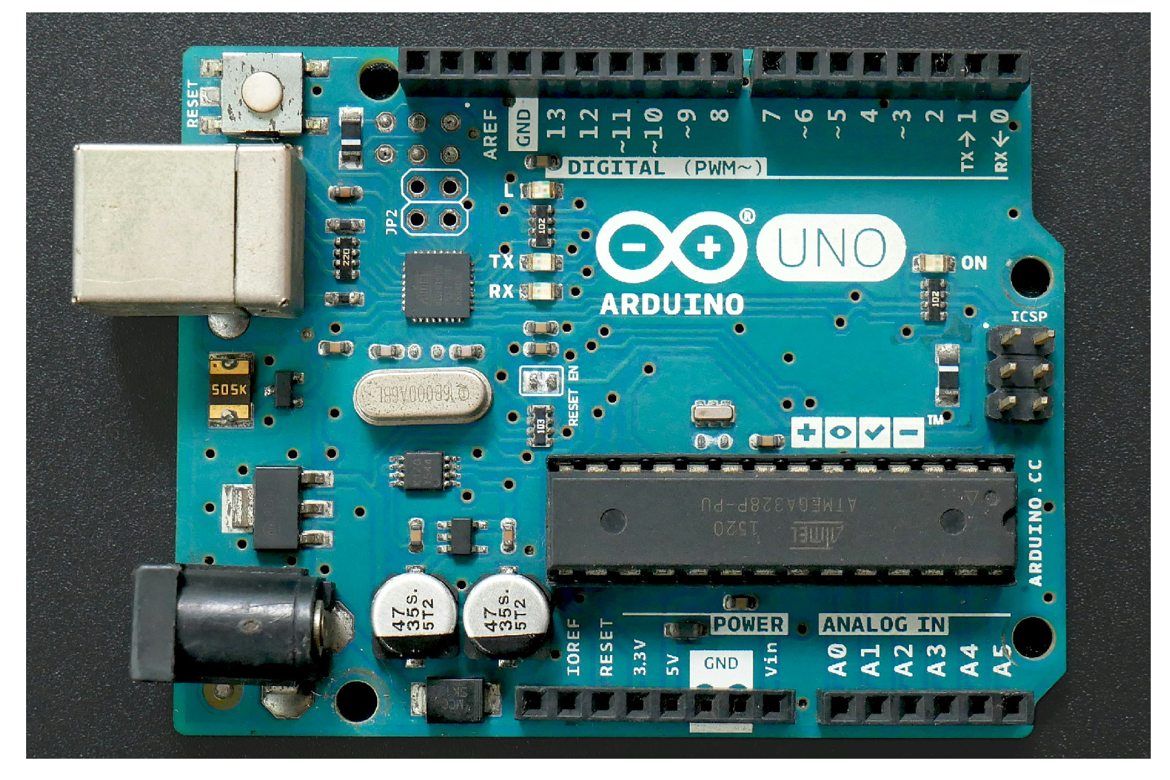
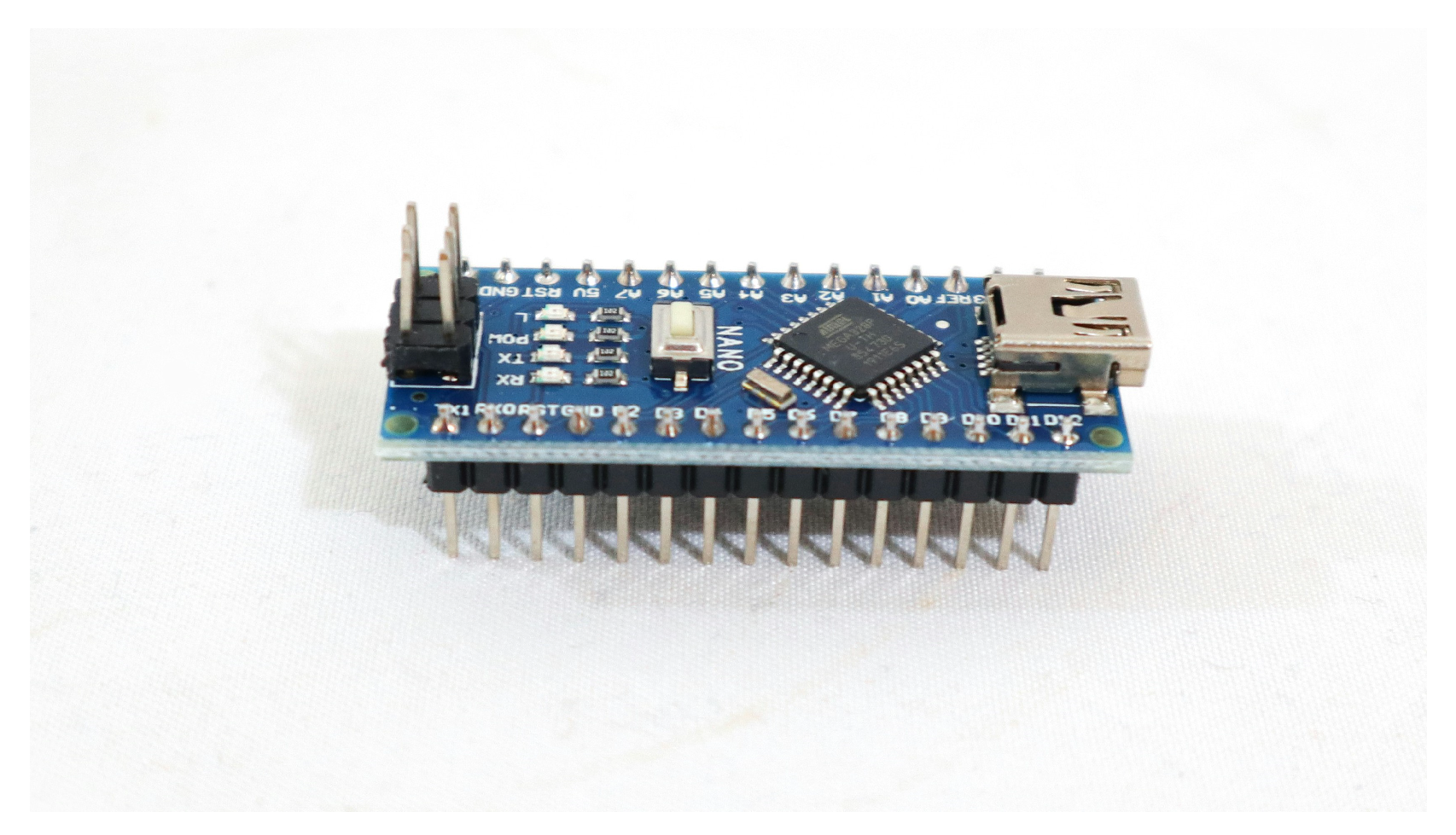
The crucial component in our experimental model is the ESP-WROOM-32 development board, a vital element for its successful implementation. Previous projects often relied on development boards like Arduino Uno or Arduino Nano, owing to their ease of programming and cost-effectiveness. However, the limitations posed by the size of the Arduino Uno made it unsuitable for our envisioned robust system designed to attach to a blind person’s cane. Considering an alternative, the smaller Arduino Nano was contemplated, but its lack of Wi-Fi and Bluetooth capabilities rendered it insufficient for our purposes.
To overcome these constraints and enhance the functionality of our experimental model, the ESP-WROOM-32 DevKit emerged as the preferred choice. One of the key advantages that tipped the scales in its favor is its incorporation of both Wi-Fi and Bluetooth technologies, addressing the connectivity needs essential for our smart cane research. Furthermore, the ESP-WROOM-32 offers a larger memory capacity and a greater number of programmable pins compared to both the Arduino Uno and Arduino Nano. This makes it a more versatile and powerful option, aligning better with the comprehensive requirements of our innovative smart cane. The programming language used by the development board can be extended through C++ libraries, like on the Arduino part. Arduino is open source, both in terms of hardware and software [
14]. For a clearer visual representation of these development boards, refer to
Figure 2 and
Figure 3 showcasing the Arduino Uno and Arduino Nano, respectively.
The selected development board for this research is, in conclusion, the ESP-WROOM-32 DevKit. The primary advantage of this board is its incorporation of the aforementioned technologies, expanded memory, and a greater number of programmable pins, rendering it more suitable and powerful overall. A comparison of the characteristics of the chosen development board with those of the Arduino Uno and Arduino Nano is presented in
Table 1.
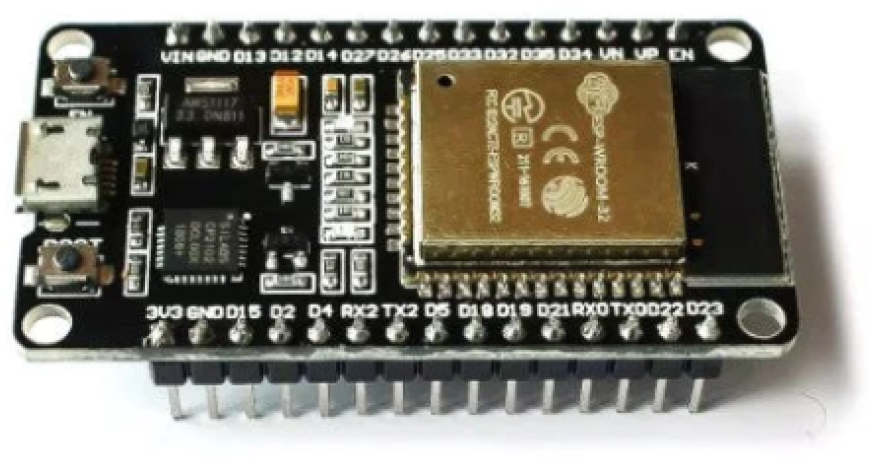
The ESP-WROOM-32 operates at a supply voltage of 3.3 [V], and its operating temperature ranges from −40 [°C] to 85 [°C]. In addition to Bluetooth and Wi-Fi, it also incorporates Bluetooth Low Energy (BLE), enabling users to connect mobile phones or transmit BLE messages. The model of the board used for the research is presented in
Figure 4, which is a powerful and reliable development board from all analytical perspectives of this experimental model. The software that was developed is subsequently implemented on this component, constituting the heart of this research.
3.2.2. Ultrasonic Sensors
The two HC-SR04 ultrasonic sensors used in implementing the solution are crucial components. These sensors are among the most widely used for measuring the distance to a target object, offering a favorable quality-to-price ratio. Since the aim for the experimental model was to be affordable for everyone interested, these ultrasonic sensors were used, which have an operating range starting from 2 cm and reaching up to 4 m. The sensor module used is depicted in
Figure 5.
These sensors aim to detect potential obstacles in the traveler’s surroundings. Ultrasonic sensors have predefined threshold limits: they operate from 3 [cm] to 3.5 [m] in most situations. The used HC-SR04 ultrasonic sensor, presented in
Figure 5, has four pins in its composition: the VCC power pin, GND ground pin, Trigger, and Echo. [
16] The operating principle is as follows: the Trigger pin, an input pin, is held “high” for a period of 10 [μs] to initialize the measurement by sending ultrasonic waves, and the Echo pin, an output pin, is held “high” for a time equal to the round-trip time of the ultrasonic wave returning to the sensor [
17].
Generally, ultrasonic sensors emit waves at a frequency higher than 20 [kHz], but the frequency of the sensors chosen for use in this research is 40 [kHz]. The distance to the reference object can be calculated, taking into account the speed of sound, which has an approximate value of 343 [m/s] or 0.0343 [cm/μs], and the time taken by the ultrasonic wave emitted by the sensor to travel through the air. Thus, using the general formula for speed, which is equal to the ratio of distance to time, the calculation formula can be expressed and used to determine the distance at which objects detected by the sensors are located. Therefore, this formula is as follows [
17]:
As mentioned earlier, the development board has a voltage drop on the output pins of only 3.3 [V], which is insufficient for the ultrasonic sensors used, requiring a supply voltage of 5 [V]. The main characteristics of these sensors, extracted from the datasheet, are presented in
Table 2.
3.2.3. Other Components Used
The haptic feedback system incorporates compact button-type vibration motors, which, weighing in at around 0.9 [g] and measuring 10 [mm] × 3.2 [mm], operate at a voltage of 3 [V] to provide tactile alerts upon detecting obstacles. In the auditory domain, adjustable passive buzzers are employed for sound notifications, offering flexibility in frequency modifications. Powering the entire system is a rechargeable 9 [V] voltage accumulator, utilizing Li-ion technology with a capacity of 5400 [mWh]/600 [mAh], ensuring both user convenience and eco-friendly recharging through USB. User control is facilitated by vertical switches, allowing seamless toggling of audio and haptic functions. Complementing these features is a radio-frequency remote control, which, operating at 12 [V] and 315 [MHz], possesses a range of 50–80 [m], aiding in locating the cane through emitted sound signals upon button activation.
3.3. System Arhitecture
In the construction of a more intricate system, the system architecture assumes a pivotal role. It serves as a framework upon which the system is built, providing information about how its parts interact with one another. The system’s capacity to fulfil the imposed requirements while maintaining reliability, scalability and efficiency is contingent upon its architecture. For the purposes of this experimental model, the block diagram representing the system architecture is presented in
Figure 6. A description of each component and its connectivity will be presented in the following sections.
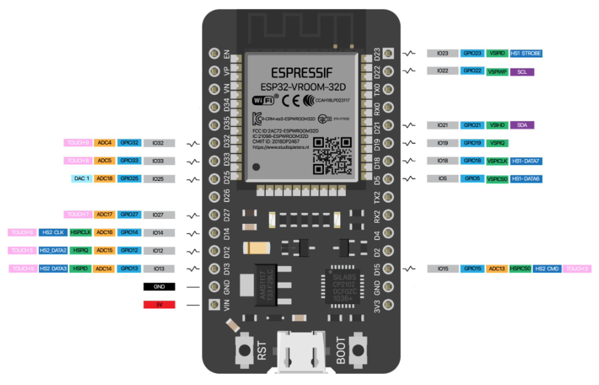
The most complex component of this system is the ESP-WROOM-32 development board. For the development of this experimental model, the chosen kit was DevKit model with 30 pins and 2 dual-core processors, as presented in the previous subsection. Out of these, 25 pins are programmable, 18 are ADC (Analog-Digital Converter) pins, 10 are GPIO pins with capacitive sensitivity (aiding in the implementation of functions like touch buttons, and touchpads), 2 are DAC (Digital-Analog Converter) pins, 3 are UART (Universal Asynchronous Receiver-Transmitter) pins, 2 are I2C (Inter-Integrated Circuit) pins, 16 are connected to PWM (Pulse Width Modulation) channels, allowing control over light intensity, motor speed, or similar applications, 2 are I2S (Inter-IC Sound) pins, and 3 are SPI (Serial Peripheral Interface) pins. In addition to these pins, there are also those related to VIN and 3.3 [V] power supply, as well as 2 GND ground pins. All this information was extracted from the development board’s datasheet.
For this experimental model, 16 pins out of the total 30 were utilized, leaving the remaining 14 unused, available for future researchs or further development of the current one. In
Figure 7 below, the used pins and their meanings are represented.
In
Figure 8, the complete hardware diagram of the entire system, namely the smart cane for the visually impaired with ultrasonic sensors, is presented. This diagram was created using the EasyEDA (Standard) tool. It is a free and user-friendly program that can run both online and on a personal computer after being downloaded. The main purpose of this program is to create and simulate electrical schematics and printed circuit boards (PCBs).
3.4. Working Principle
Figure 9 illustrates the functioning of the entire system through a flowchart. The central element is the microcontroller, which has not been included in it. This element controls all the components in the system.
When the power switch is activated, the system initiates its operational functions, including the ultrasonic sensors and mobile application. Once the system has been initialized, the sensors commence scanning for obstacles. Upon the detection of an obstacle, the sensor data is transmitted to the microcontroller, where it is used to calculate the distance to the obstacle. The system mode (indoor or outdoor) is set by the system switch. If the obstacle is within a predefined distance threshold and both the haptic and sound alert switches are activated, an alert is triggered. In the event that only one alert switch is activated, the corresponding alert will be triggered.
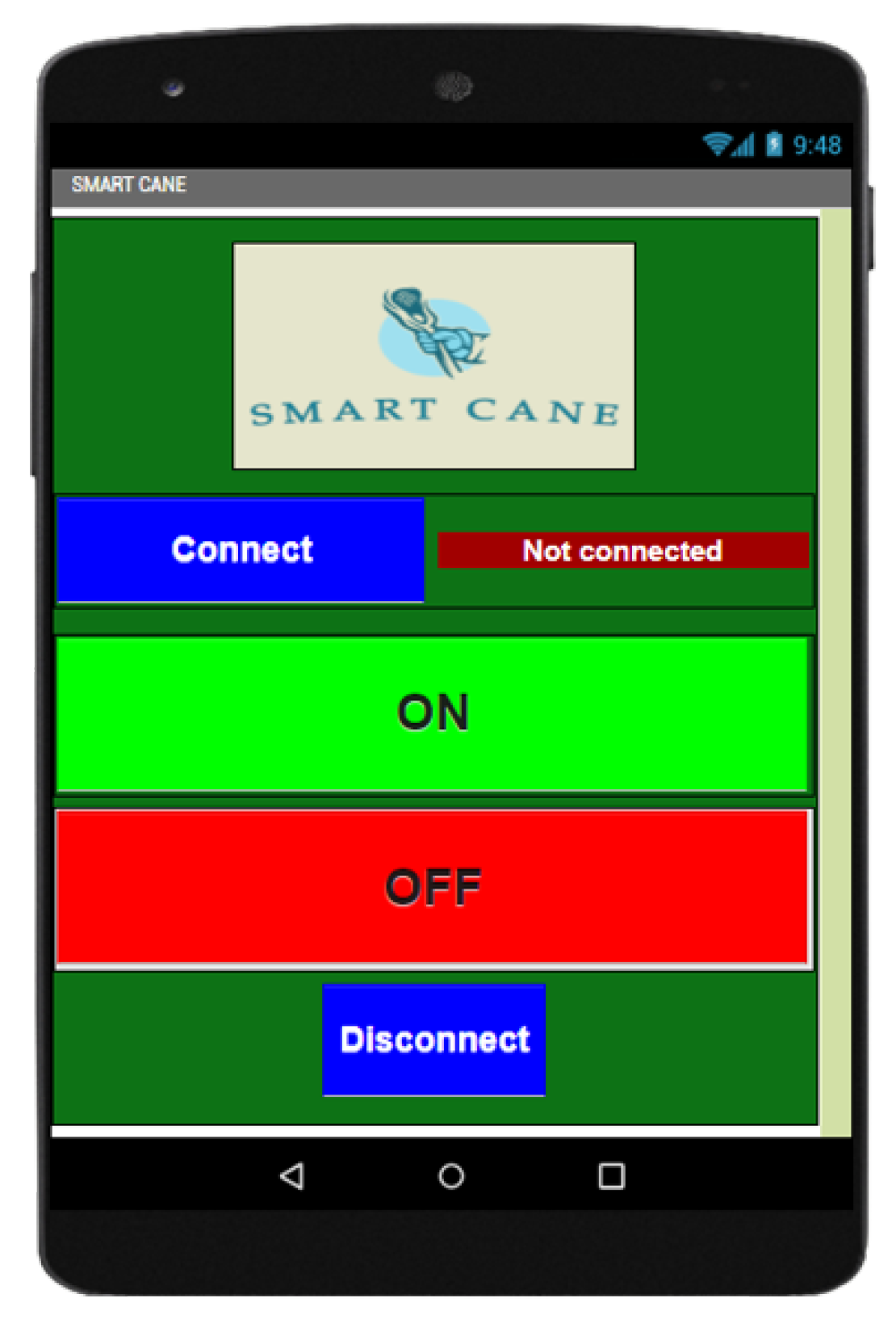
On the mobile application branch, after its execution, the next step is to establish a Bluetooth connection between the application and the development board. Upon successful connection, the user can change the buzzer state using buttons in the application, enabling the start and stop of sound alerts through the buzzer to locate the cane in case of loss. This is possible even if the audio alert switch is in the OFF state.
If the power switch is in the OFF state, the system will not function, and the cane will act as a traditional support cane for visually impaired individuals.
3.5. Software Implementation
In the implementation of the final algorithm, the microcontroller code was developed using the Arduino IDE. Pin assignments for various components were defined using the “#define” directive in the C/C++ programming language. This approach allowed the use of symbolic names for constant values, improving code readability. Pins for ultrasonic sensors, vibration motors, audio components, and switches were identified using this method.
The next step involved setting threshold distances for the ultrasonic sensors based on the system’s operating mode (indoor or outdoor). Three threshold distances were defined for each mode. Global variables, such as sound speed and various switch states, were initialized in the code.
The core functionality of obstacle detection and alerting was implemented in the “loop()” function. The distances from ultrasonic sensors were continuously monitored, and alerts were triggered based on predefined threshold values. The alert system included both haptic (vibrations) and audio (buzzer and headphones) signals. The code allowed users to customize alert preferences through switches, providing flexibility in system behavior.
Additionally, a Bluetooth-enabled mobile application was developed using MIT App Inventor 2, an online platform for mobile app design [
18]. Initially developed by Google and currently maintained by the Massachusetts Institute of Technology (MIT), MIT App Inventor 2 aims to assist users who may not be proficient in traditional programming by employing a block-based programming approach. The platform provides pre-built components like buttons and labels, making it efficient for building mobile applications. Utilizing a “drag and drop” method, the application interface, depicted in
Figure 10, was easily constructed. The visual programming approach enhances user-friendliness and accessibility, aligning to facilitate mobile app development for individuals with limited programming expertise.
3.6. Experimental Setup
To integrate all the components into a functional and reliable system, their placement on the cane is based on their size and function. To ensure that users can feel the signals through vibrations, the position of the vibration motors was on the handle of the cane. Below the handle was created a space for the switches related to the cane’s functionalities.
Recognizing the need for users to easily activate or deactivate the entire system, the switch responsible for this is at the top of the support. Simultaneously, for easier memorization of switch functionalities, the system mode switch is on the left side of the support, with the switches for audio and haptic alerts on the right.
The positioning of the vibration motors was influenced by the hand’s placement on the handle. There were used three motors because a single one was insufficient to perceive vibrations effectively. After testing with one and two motors, the conclusion was that three motors were adequate for my experimental model, ensuring users could sense vibrations when encountering obstacles.
Figure 11 illustrates these components, showing two motors on one side of the handle and the third on the opposite side.
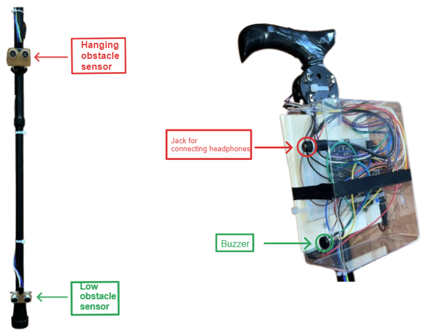
To explain the placement of other essential components,
Figure 12 illustrates the assembly of ultrasonic sensors, the buzzer, and the Jack plug on the cane. The two sensors were placed at the base and approximately in the middle of the cane, angled at about 45 degrees to detect obstacles perpendicular to the user’s path.
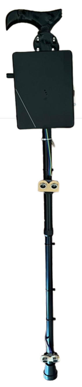
After assembling all the components on the cane and testing its functionalities, the entire circuit was covered with a plastic cap, later concealed with a black cover for a more aesthetically pleasing effect. The assembled circuit can be observed in its entirety in
Figure 13.
The cane has a compact appearance, uncluttered by wires and various components, making it easy for me to handle. The cane is one meter long but its height can be adjusted as well as the position of the sensor on it. Now, the sensors are positioned 10 cm and 60 cm from the ground, as a stick has been created for medium height. The cane weighs approximately 600–650 g with all components attached, making it easy and simple to handle. In terms of the water resistance of the circuits, they are encased in a plastic case which increases their resistance to moisture and wind. The casing covering the basic circuit is located under the cane’s handle. As in any field, improvements can be made, and thus, this research represents only my experimental model of a cane with ultrasonic sensors designed for individuals with visual impairments.
4. Results and Discussions
The testing phase stands as a pivotal juncture in the iterative process of refining an experimental model, playing a critical role in elucidating the model’s practical performance in real-world scenarios. This phase is strategically designed to furnish an impartial and comprehensive evaluation of the system’s efficacy, providing an unbiased estimate of its predictive capabilities. By conducting these tests under genuine, non-laboratory conditions, the scope is to capture the model’s performance in an authentic environment, free from artificial enhancements that might influence measurement quality.
The primary objective of this rigorous testing is to ensure the authenticity of the model’s performance, steering clear of any distortions that could arise from manual adjustments made to validation data. This meticulous approach not only yields a genuine measure of the model’s real-world functionality but also contributes significantly to the holistic evaluation of its effectiveness and potential impact.
In the specific validation process of the experimental model illustrated in
Figure 13, a series of comprehensive tests were conducted in a real-world environment. This environment intentionally lacked the controlled conditions of a laboratory setting and eschewed any features that could artificially amplify measurement quality. The testing protocol involved the collection of five measurements for six distinct distances from an obstacle, with the obstacle represented by a sufficiently large wall for identification purposes. The wealth of data gleaned from these tests, recorded with precision, is systematically documented in the detailed tabulation presented in
Table 3.
As shown in the table, for each actual distance measured with the ruler, data was collected five times to calculate an average distance obtained from the sensors. This approach is taken because inexpensive sensors may introduce errors. These errors were calculated as an average of the errors obtained in each measurement for each distance interval. The average error was then expressed as a percentage using Equation (
2), where “
” is the actual distance measured with the ruler, and “
” represents the distance obtained from the sensor.
Additionally, a comparison between the actual and measured distances was conducted. As shown in
Figure 14, the differences are not significant, indicating the reliability of the system.
The validation phase emerges as a pivotal juncture in the iterative refinement process of the experimental model, assuming a critical role as a benchmark for an exhaustive evaluation of its performance in comparison to an array of existing models. The relentless pursuit of precision and accuracy during this phase becomes indispensable, wielding a profound influence on the overarching dependability, reliability, and robustness of the system.
Upon delving into a comprehensive analysis of the outcomes stemming from the proposed experimental model, a resounding affirmation of its stature as a beacon of reliability within the expansive domain of assistive devices for individuals with visual impairments becomes evident. The system not only showcases an extraordinary average accuracy of 98%, a remarkable feat in itself but also distinguishes itself as a pertinent solution when subjected to an intricately objective comparative assessment against a diverse spectrum of models. This evaluative scrutiny unfolds meticulously in the illuminating tableau of
Table 4, providing a nuanced and insightful perspective on the experimental model’s prowess and its distinctive standing among contemporary assistive technologies.
From
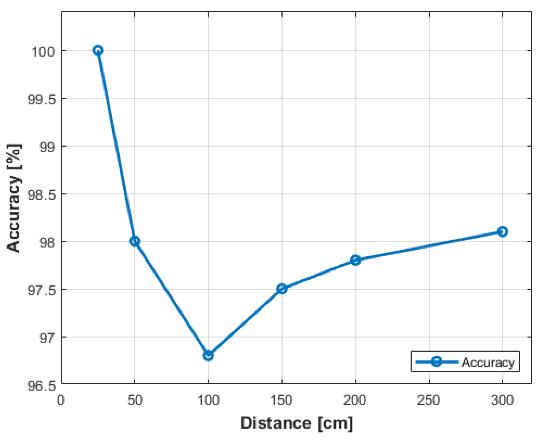
Table 3, it can be observed that the maximum accuracy, 100%, was achieved when the obstacle was placed at a distance of 25 [cm], while the lowest accuracy, 96.8%, was recorded at a distance of 100 [cm]. In
Figure 15, the evolution of the system’s accuracy is graphically depicted based on the real distance at which the object was positioned.
Concurrently, a perusal of the graphical representation delineated in
Figure 16 unveils a succinct yet illuminating insight into the system’s error dynamics. This graphical elucidation harmonizes seamlessly with the accuracy metrics of the model, meticulously calculated through the nuanced lens of Equation (
2). As the graph unfolds its narrative, a striking revelation comes to light—the system consistently maintains an average error rate below 2%. This empirical revelation serves as a testament to the system’s heightened relevance in the expansive landscape of existing solutions, solidifying its stature as a beacon of precision and efficacy.
Furthermore, in an endeavor to ascertain the system’s efficacy across diverse real-world scenarios, a comprehensive array of tests was conducted to evaluate its adeptness in detecting obstacles crafted from an assortment of materials. The sensors showcased commendable proficiency in discerning various surfaces and objects, including cabinets, stairs, and mirrors. Nevertheless, a nuanced challenge surfaced when the sensors grappled with detecting objects positioned on coarse surfaces, wherein the undulating waves tended to be absorbed by these particular materials. The encapsulated outcomes of these discerning tests are meticulously documented in
Table 5, providing a nuanced exposition of the system’s material-specific detection prowess.
As shown in
Table 5, the sensors detect different obstacles very well, except for those with a rough surface. This type of surface was detected by the sensors six times out of ten trials. This is because the transmitted waves can be distributed at different angles to the angle at which the sensor expects to receive a wave. This can also happen when the sensor sends waves from one angle and they are reflected by obstacles in other directions. This is why sensor calibration on the stick has played a very important role in obstacle detection. These types of measurements were made by visually impaired people to be most relevant to our type of system. Other experiments have been carried out by the blind, such as taking an obstacle course from one point to another, and the results have been good.
The final step in the validation process was to analyze the accuracy of the ultrasonic sensors and validate their use against other types of sensors. So,
Table 6 shows the comparison between the characteristics of the sensor types that could have been used in the research.
Due to the research’s objective of achieving low implementation costs, the choice of sensors came down to infrared and ultrasonic options. After conducting numerous tests and analyzing the characteristics of these sensor types, ultrasonic sensors were selected. This decision was based on their larger distance range and broader bandwidth. Another significant advantage is that ultrasonic sensors are minimally affected by atmospheric conditions in the surrounding environment, as the speed of sound is proportional to temperature. This ensures more reliable measurements under various temperature conditions. Considering all these aspects, the validation of the proposed experimental model is conducted objectively, making the proposed smart cane for visually impaired individuals a reliable and robust solution.
5. Conclusions and Future Steps
Within the research, the goal was to create an experimental model of a smart cane to assist people with visual impairments. We chose this theme because the aim was to develop a system that enhances the independence and mobility of these individuals. The experimental model was created using ultrasonic sensors. As mentioned in the first chapter of this work, one of the most crucial sensory senses is vision, as it must replace smell and hearing when these are absent. Moreover, it constitutes the first sense that detects the path one takes from one place to another, an activity everyone performs daily. Therefore, the main challenge faced by visually impaired individuals is mobility and orientation. To improve these factors, the white cane for the blind was introduced in 1940, and it now serves as the primary assistance system for the blind.
Over time and with technological advancements, various types of canes have emerged, evolving in terms of length, material, and the issues they address. The longer the cane, the faster it detects obstacles, providing the user with more reaction time. Traditional canes can detect obstacles within a maximum distance of one meter, depending on the user’s height and the cane’s tilt angle. However, a major issue is the obstacle localization time, as users are only alerted after making contact, resulting in a longer detection time. These issues have been addressed in this research by implementing a smart cane with ultrasonic sensors, which are used to detect obstacles. These obstacles can be low or hanging, requiring the use of two sensors, one for each type of obstacle. The operating range of the sensors is between 2 [cm] and 400 [cm]. To create a reliable smart cane in various situations, obstacle warnings can be delivered through both haptic and audio alerts played through headphones and a buzzer. Users can start and stop these alerts using two vertical switches. Another switch allows users to choose the system mode, as it contains two modes of operation: indoors and outdoors. Another intelligent functionality implemented was a mobile application connected to the development board via Bluetooth, enabling the triggering of audio signals from a buzzer in case of cane loss. A backup solution was also implemented using a radiofrequency remote control with the same purpose. Following all the proposed steps in creating this system, an experimental model was developed to alert the user in advance if there is an obstacle in their walking path, preventing collisions. The closer the distance, the more frequent the signals to warn the user of approaching obstacles. In this way, visually impaired individuals can avoid collisions using a rechargeable and robust experimental model.
The biggest advantage of this system is the very low cost, which is one of the main objectives achieved. The total cost was about which makes it a very strong competitor on the market compared to other systems such as: the WeWALK device which has a cost of with some extra features or the Phoenix device with a price of about , which is double the proposed system. The price includes the time and work developed, which would be a big plus for it.
For testing and validating the model, real-world scenarios were created, and the obtained results were very good. The model has an accuracy of 98%, which, when compared to other models of assistance systems for visually impaired people, is exceptionally good. The system can recognize objects made of various materials, providing robustness. Another important aspect is the cost. This experimental model was created at a very low cost compared to existing models on the market, as studied earlier in the work. Therefore, the model manages to be a combination of important functionalities of the studied models but at a much lower cost.
Any field can undergo improvements with the development of technology and automation. The smart cane created in this research is just an experimental model and may contain improvements, either in terms of functionality or appearance. One potential improvement could involve introducing a GPS (Global Positioning System) module to track the cane’s location in case of loss or to provide assistance to the user. Another aspect could be the incorporation of a fall sensor to monitor the user’s condition during system usage and cover the possibility of the user hitting an obstacle and falling.
One idea that could improve this system and bring it to life would be to include deep learning or machine learning for the results obtained from the ultrasound sensors, but also in the event of obstacle detection with the camera. Some methods that could be relevant for the application of deep learning are also presented in [
26].
Another idea for improving this experimental model could be replacing the wired headphones with a Jack socket for audio alerts in Bluetooth-connected headphones. Unlike the previous ideas that required additional components, this development idea does not need extra components as the development board incorporates the Bluetooth technology module. This aspect would make the cane more in line with current technology trends, where most users prefer Bluetooth-connected headphones over wired ones.
On the other hand, changing the appearance of the cane could be another enhancement to this research. Creating a cane with fewer but more powerful vibration motors would reduce the number of components used in the system and improve the cane’s appearance. Additionally, further development could involve integrating ultrasonic sensors with a camera for image processing and obstacle detection and filtering. If this feature is desired, cost considerations should be taken into account, as it was a deciding factor in the system created in this research.
In conclusion, after testing and validating the experimental model, it can be summarized that a reliable and robust smart cane for visually impaired individuals has been created, with high accuracy and low cost, thereby increasing the user’s reaction time. The primary goal of improving the quality of life for people with visual impairments has been achieved, along with the secondary objectives of the research.


