Article

Experimental Study on Ignition and Pressure-Gain Achievement in Low-Vacuum Conditions for a Pulsed Detonation Combustor

by
Andrei Vlad Cojocea
1,2,3,*,
Mihnea Gall
1,2,3,
George Ionuț Vrabie
1,2,
Tudor Cuciuc
1,4,
Ionuț Porumbel
1,*,
Gabriel Ursescu
1 and
Daniel Eugeniu Crunţeanu
3,*
1
Romanian National Research and Development Institute for Gas Turbines COMOTI, 061126 Bucharest, Romania
2
Doctoral School of Aerospace Engineering, National University of Science and Technology POLITEHNICA Bucharest, 011061 Bucharest, Romania
3
Faculty of Aerospace Engineering, National University of Science and Technology POLITEHNICA Bucharest, 011061 Bucharest, Romania
4
Institute of Applied Physics, Moldova State University, MD-2028 Chisinau, Moldova
*
Authors to whom correspondence should be addressed.
Technologies 2024, 12(12), 252; https://doi.org/10.3390/technologies12120252
Submission received: 15 October 2024 / Revised: 11 November 2024 / Accepted: 28 November 2024 / Published: 2 December 2024
(This article belongs to the Special Issue Technological Advances in Science, Medicine, and Engineering 2024)

Abstract

:
Pressure-gain combustion (PGC) represents a promising alternative to conventional propulsion systems for interplanetary travel due to its key advantages, including higher thermodynamic efficiency, increased specific impulse, and more compact engine designs. However, to elevate this technology to a sufficient technology readiness level (TRL) for practical application, extensive experimental validation, particularly under vacuum conditions, is essential. This study focuses on the performance of a pulsed-detonation combustor (PDC) under near-vacuum conditions, with two primary objectives: to assess the combustor’s ignition capabilities and to characterize the shock wave behavior at the exit plane. To achieve these objectives, high-frequency pressure sensors are strategically positioned within both the vacuum chamber and the combustor prototype to capture the pressure cycles during operation, providing insights into pressure augmentation over a period of approximately 0.5 s. Additionally, the Schlieren visualization technique is employed to analyze and interpret the flow structures of the exhaust jet. The combination of these experimental methods enables a comprehensive understanding of the ignition dynamics and the development of shock waves, contributing valuable data to advance PGC technology for space-exploration applications.

1. Introduction

Currently planned interplanetary missions largely depend on Hohmann transfer orbits, which minimize the required Δv (the change in velocity that a spacecraft needs to perform a specific maneuver or mission) by using two impulsive engine burns: one to initiate the transfer orbit and another to adjust it upon arrival at the target. Between these burns, the spacecraft travels without propulsion, relying solely on inertia. While Hohmann transfer orbits remain the cornerstone for current interplanetary missions due to their fuel efficiency, they come with notable trade-offs, primarily lengthy transit times [1,2]. However, recent studies have explored methods to optimize these trajectories by reducing fuel consumption or shortening travel times. The standard Earth-to-Mars trajectory using this method, for example, takes approximately nine months. This lengthy duration poses significant risks to crewed missions, such as extended exposure to space radiation and the adverse effects of prolonged weightlessness on human health. Additionally, the spacecraft is at risk of damage from micro-collisions during the long, coasting phase between the initial and final impulsive burns [3].
Approaches like combining chemical and electric propulsion systems or using gravity assists have been proposed to minimize both Δv requirements and transit durations, offering safer alternatives for future manned missions to Mars [4,5]. These advanced techniques aim to strike a balance between energy efficiency and crew safety, showing promise for reducing the time spent in space and mitigating the associated risks.
Alongside these innovations, pressure-gain combustion (PGC) is being explored as a next-generation propulsion system. These engines leverage controlled explosions to generate rapid thrust, offering higher thermodynamic efficiency compared to traditional chemical propulsion [6]. Other advantages of PGCs over classic propulsion methods are simpler design, reduced specific weight, and the absence of moving parts. Furthermore, during a recent workshop on innovative propulsion organized by the European Space Agency (ESA) through the Innovative Propulsion Cross-Cutting Initiative (IPCCI) program, it was estimated that PGCs achieve an increase in performance of up to 25% versus classical propulsion approaches, and the detonation propulsion technology was deemed a mission enabler [7]. Hence, the scientific community anticipates that, by integrating PGCs into mission designs, there is potential for even faster and more efficient transit, which could further enhance mission safety by reducing both fuel consumption and the duration of space travel.
However, despite the promising potential of integrating PGCs into mission designs, several critical challenges are identified that must be addressed to advance the TRL for practical space applications. At the same ESA workshop, a major issue raised during discussions was the difficulty of achieving consistent ignition and sustained detonation in vacuum conditions [7]. This challenge is particularly pronounced in the vacuum of space, especially within the exhaust environment of engines, where reliable detonation initiation becomes a significant obstacle. Overcoming this barrier is essential for the successful implementation of PGC-based propulsion systems in future space missions.
According to Paschen’s Law, “the voltage required to produce an arc across a gap decreases as pressure is reduced, but eventually increases after a certain point, exceeding its initial value” [8]. In partial vacuum conditions, fewer molecules are present for ionization within the electric field between the spark plug electrodes, requiring more energy to initiate the chain reaction needed for an electric arc. This creates additional complexities when attempting to ignite combustion in propulsion systems using spark plugs, particularly when the pressure falls within a range that significantly elevates the voltage needed for arc generation. Recent studies have also analyzed how the geometric configuration of spark plugs and atmospheric conditions like humidity further complicate ignition under vacuum conditions [9,10].
The primary detonation combustors explored for space propulsion applications include the pulsed-detonation combustor (PDC) and the rotating-detonation combustor (RDC) [11,12]. A third type, the oblique-detonation wave combustor (ODWC), has received comparatively less focus. This is largely because the formation of stable detonation waves in ODWC presents considerable challenges, limiting its practical implementation so far. Despite its theoretical advantages, the instability associated with the detonation wave in ODWC remains a significant barrier to its development for space applications [13,14].
PDCs follow a cycle of filling, ignition, detonation, and purging, with filling speed being a key factor that limits cycle frequency and impacts performance [15]. Enhancing the deflagration-to-detonation transition (DDT) requires high turbulence to achieve sufficient flame acceleration. However, most studies focus on component-level development to enhance mixing, in order to increase turbulence and flame acceleration, rather than advancing the TRL under practical conditions, limiting broader applications [16,17,18,19,20,21].
A significant advancement in this field comes from Japan Aerospace Exploration Agency (JAXA) tests of both a PDC [22] and an RDE [23] in space, integrated in the S-520-31 sounding rocket mission, which demonstrated a TRL of 5 for these propulsion architectures. These tests mark the first PDE- and RDE-operated flight in space, demonstrating the potential of detonation-based propulsion for future space missions. The PDC experiment highlights key operational aspects such as ignition, detonation wave propagation, cycle repeatability (14 cycles), and performance (pressure and temperature data) under space conditions [22].
The existing research on detonation behavior in vacuum conditions includes several studies, though few focus specifically on the challenges of ignition and initiation. Most investigations are centered on singular explosions, rather than continuous propulsion systems for space. Cooper et al. [24,25] examined how sub-atmospheric pressure impacts DDT in a PDC and the resulting impulse generation. Similarly, Zhdan [26] conducted a theoretical study on the structure of steady detonation waves in a vacuum, with conclusions that align with the present study’s findings, discussed later. Research into singular explosions includes that of Zhdan and Prokhorov [27], who developed a mathematical model for detonation initiation in vacuum suspensions, and Pinaev [28], who demonstrated self-sustained detonation of secondary explosives in such conditions. A recent study [29] further explores detonation characteristics and energy release patterns of Hexahydro-1,3,5-trinitro-1,3,5-triazine (RDX) explosives in a vacuum environment.
Several studies explore the performance of pulsed-detonation rocket engines (PDREs) under atmospheric conditions, both numerically and experimentally. Morris et al. [30] conducted detailed numerical simulations to model single-pulse gas dynamics and the overall performance of PDREs, providing valuable insights into combustion efficiency and exhaust velocity optimization. Yan et al. performed experimental investigations on PDREs with various injectors and nozzles, further enhancing the understanding of PDRE behavior in different configurations [31]. These works, alongside other studies like those of Wang et al. [32] and Alam et al. [33], provide a comprehensive understanding of detonation initiation, cycle frequency, and performance optimization, helping advance the development of PDRE technology under relevant conditions.
This paper presents experimental investigations into near-vacuum ignition and pressure-gain cycles in our PDC prototype, advancing it to TRL 5. Building on prior research [34,35,36,37,38], which explored PDC performance under atmospheric conditions, fuel/oxidizer strategies, and detonation wave dynamics, this study extends the analysis to near-vacuum environments, a critical step towards achieving a practical combustor for space applications. The findings derived from high-frequency pressure sensor data, which prove pressure gain-type trends, and high-speed Schlieren photography, which provides key insights into waves’ behavior under low-vacuum conditions, marking significant progress in our PDC development. It is important to note that this paper primarily focuses on investigating the ignition process and the ability of the PDC to sustain pressure-gain cycles under near-vacuum conditions. It is not intended as a comprehensive study on either the performance of the combustor in these conditions or the methodologies used for measurement.

2. Materials and Methods

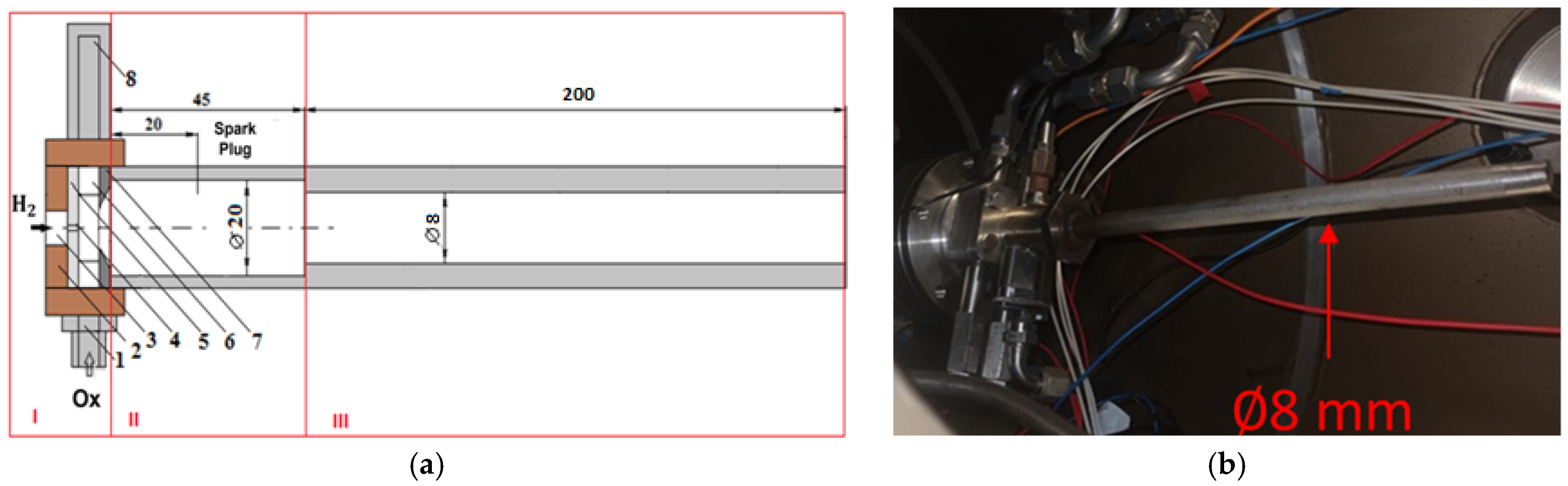
2.1. Experimental Design

Passive control methods are integral to the aerodynamic system of our PDC prototype, both enhancing the mixing efficiency and enabling high-frequency operations. The gas injection process utilizes the jet in cross-flow (JICF) technique, which ensures the effective mixing of hydrogen with the oxygen cross-flow. This is further optimized by injecting the gases into a ring-shaped chamber, which promotes the formation of alternating-direction vortices through oxygen planar jets. To support and amplify high-frequency detonation cycles, Hartman–Sprenger wave generators are employed. These resonators regulate the frequency of the counter-rotating vortex structures formed within the chamber, promoting sustained high-frequency oscillations. The diagram of the prototype is shown in Figure 1. Further details regarding its components, operating principle, and measured performances can be found in our previous work [34,35,36,37,38]. These references cover various aspects of the prototype’s design and operational characteristics, offering comprehensive insights into its functionality and testing outcomes.
One important design modification from the earlier tests conducted under atmospheric conditions is the change in the III—detonation channel diameter (Figure 1a). After several unsuccessful attempts in vacuum conditions using the original configuration, the channel diameter was reduced from 15 mm to 8 mm. This adjustment was made to increase the residence time of the combustible mixture in the ignition section, thereby introducing an obstacle to the high-speed flow imparted to the mixture via the vacuum conditions in both the premixing and ignition sections. This change helped address issues related to detonation initiation in the vacuum environment.
Another key modification focused on the ignition device. In earlier atmospheric tests, a standard automobile spark plug was used. However, it was observed that, under vacuum conditions, the spark supply power drops by nearly fivefold (Figure 2). This reduction in intensity under vacuum posed significant challenges for reliable ignition, necessitating a re-evaluation of the ignition system for improved performance in low-pressure environments.
In place of the standard spark plug, a decommissioned gas turbine (GT) engine spark plug is employed to boost ignition power (Figure 3). However, this spark plug operates at a fixed frequency, which cannot be adjusted. As a result, the operating frequency is set to 10 Hz and used as such during the vacuum tests. All these design modifications, including the spark plug upgrade and adjustments to the detonation channel, are necessary to successfully achieve ignition under exhaust vacuum conditions.

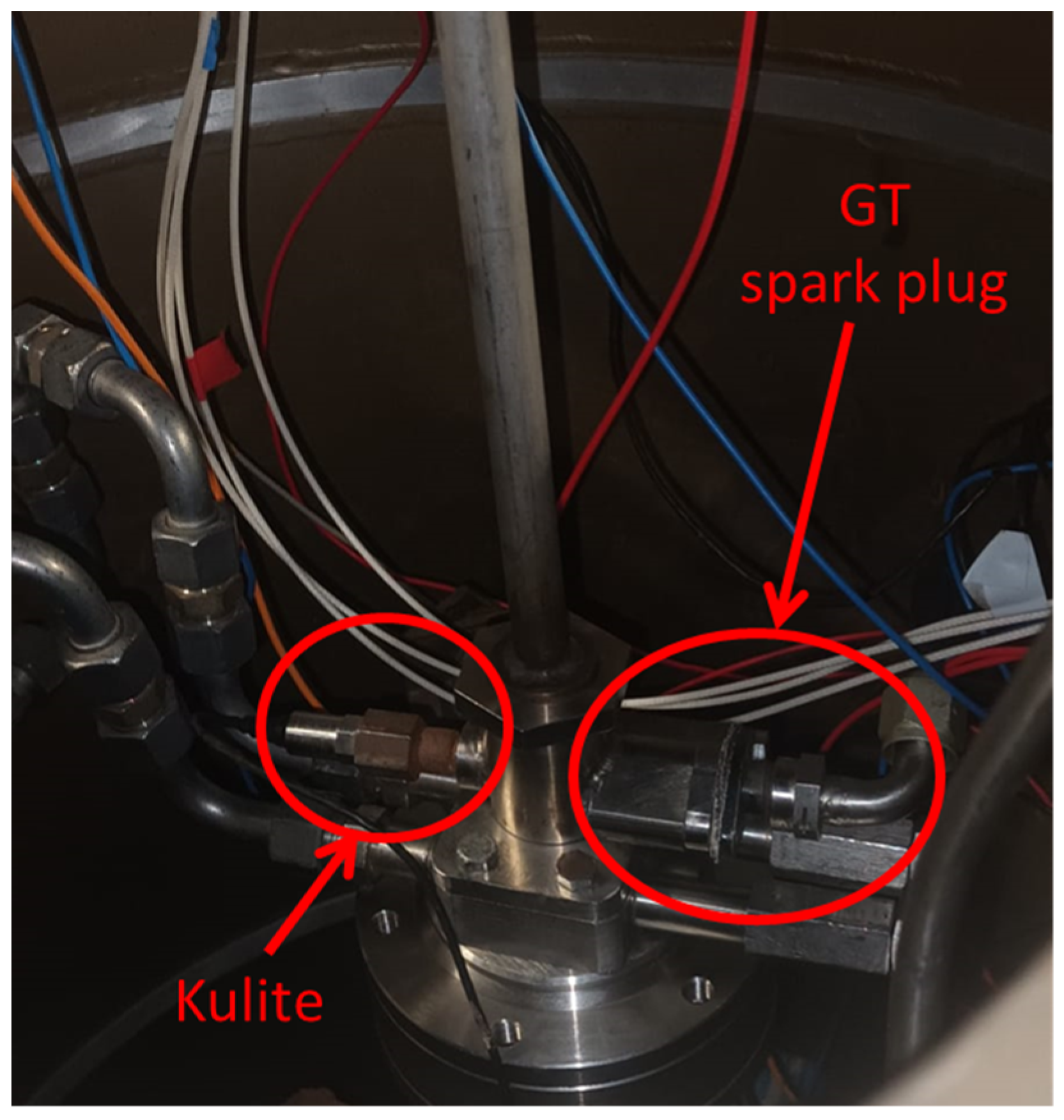
2.2. Experimental Setup

The experimental setup includes two gas supply lines: one for oxygen, with a supply pressure of up to 20 bar at ambient temperature and a flow rate of 0.2 kg/s, and another for hydrogen, also at up to 20 bar and a flow rate of 0.05 kg/s. Both lines are equipped with ALICAT MQ-250SLPM-D and ALICAT MQ-2000SLPM-D flowmeters (from ALICAT Scientific Inc., Tucson, AZ, USA), which provided precise measurements of the pressure, flow rate, and temperature. These measurements are crucial for calculating the equivalence ratio during the experiments. Further details on the test rig and its operation can be found in reference [37].
A pressure sensor (Kulite ETM-HT-375 (M) from Kulite Semiconductor Products, Inc., Leonia, NJ, USA) sensor is positioned in the ignition section of the PDC, directly opposite the spark plug, as illustrated in Figure 3, to perform rapid static pressure measurements. A second identical pressure sensor is placed inside the vacuum chamber to capture high-speed chamber pressure data. Both sensors have an operating capacity of up to 35 bara and a 3 kHz bandwidth, with typical non-linearity, hysteresis, and repeatability of ±0.5% FSO. Their natural frequency exceeds 400 kHz, and they have an acceleration sensitivity of 1.1 × 10 4 % FS/g. The sensors are calibrated across a range of 1 to 20 bar in 0.5 bar increments, with linear regression transfer functions yielding R2 values of 0.99990 and 0.99999. Data are sampled at a rate of 20 kHz, and the averaged results are presented in the following section.
The Schlieren imaging technique is employed to capture flow-field structures at the exhaust of the PDC, immediately downstream of the detonation channel, as depicted in Figure 4. For visualization, an IRIS Broadcast scientific imaging system (from IRIS Broadcast Services, Constanța, Romania), equipped with 10” parabolic mirrors, is utilized. This system is paired with a Phantom VEO 710L high-speed camera (from Vision Research, Wayne, NJ, USA), operating at 77,000 fps with a 256 × 256 pixel resolution and a 1 µs exposure time. Further details on the Schlieren system setup can be found in references [34,37].
Several attempts were made to calibrate the Schlieren imaging system; however, the image quality suffered primarily due to the effects of the vacuum environment. This results in reduced light intensity and contrast, making it more difficult to capture sharp flow structures. The vacuum environment alters the refractive index, which affects the Schlieren imaging setup, as light beams are less scattered compared to atmospheric conditions [39]. Additionally, the vacuum chamber windows contributed slightly to the degradation in image quality. As a result, the images presented in the results section are of lower quality compared to those obtained under atmospheric conditions, as documented in previous studies [34,37].
The reported tests were carried out for a hydrogen–oxygen mixture at a fuel line set pressure of 7.5 bar, and an oxidizer line set pressure of 5.5 bar, corresponding to an ER of 0.048. The experimental setup was placed in a vacuum chamber, where the ambient pressure was reduced to 15 mbar at the start of each test. This vacuum condition is representative of near-space environments, and it allows for the evaluation of detonation-wave behavior under reduced-pressure conditions.

3. Results and Discussion

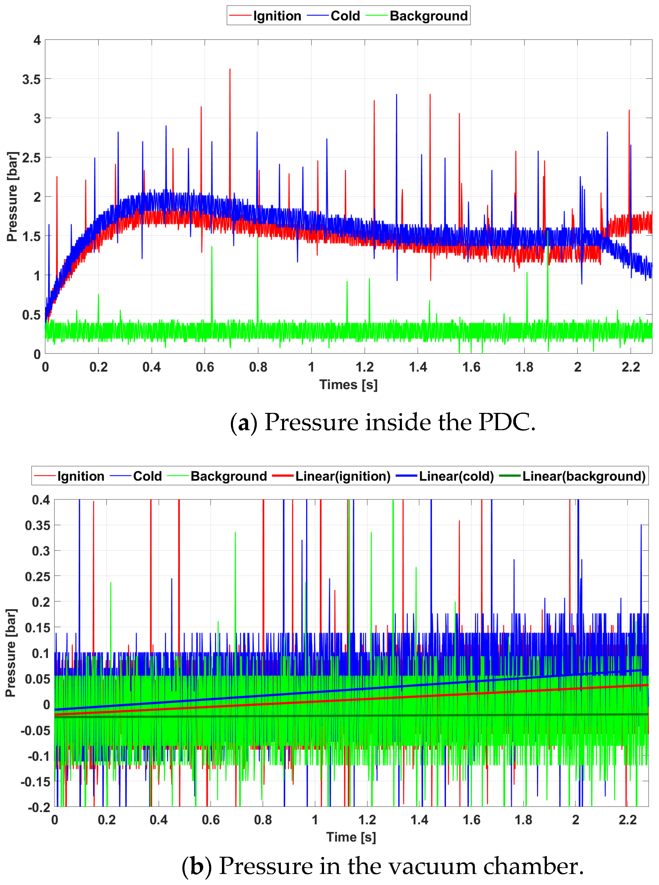
3.1. Pressure Data Analysis

Figure 5 illustrates the pressure data recorded via the two sensors, with the top graph showing the readings from the sensor located inside the PDC (depicted in Figure 3) and the bottom graph representing the pressure within the vacuum chamber. For each sensor, three signal sets are displayed. The green lines indicate background noise (Figure 5c), captured with no gas flow and the spark plug power supply turned off. The data reveal significant noise, largely attributed to the electrical connections required to route the sensor wiring through the vacuum chamber walls, where grounding proved insufficient. This grounding issue introduced interference that affected the baseline readings, highlighting the technical challenges of maintaining signal integrity.
The second set of pressure signals, displayed in Figure 5d with the blue line, was recorded during a cold flow test. In this setup, oxygen was allowed to flow into the PDC, and the spark plug was activated, but no hydrogen was introduced. Along with the elevated noise levels, the Kulite pressure probe (as seen in Figure 3) also picked up the electromagnetic interference generated via the spark plug, which is evident in the sharp spikes in the blue line. These spikes occur at the same frequency as the spark plug’s operation, and without careful analysis, they could easily be mistaken for pressure signals caused by sustained pressure-gain cycles, potentially leading to misleading conclusions about the test results.
The third set of signals, shown in Figure 5e, was captured during the actual ignition and combustion test, with both pressure sensors active. In this test, the spark plug was operational, and both oxygen and hydrogen were supplied to the PDC. The time origin on the graph corresponds to the simultaneous opening of the oxidizer and fuel valves during the ignition test, as well as the opening of the oxidizer valve alone during the cold test. Although the noise and electromagnetic interference from the spark plug persisted, the pressure inside the PDC (top graph) increased as gas was fed into the thruster. Meanwhile, the vacuum chamber pressure (bottom graph) rose more gradually, somewhat masked by the noise but still visible in the trend, as the escaping gas filled the vacuum chamber.
After the pressure inside the PDC reached its peak, mainly due to inertial effects, the gas began expanding into the exhaust pipe and vacuum chamber. This expansion drove the system toward an equilibrium as the pressure equalized between the PDC and the surrounding environment. The pressure within the PDC remained significantly higher than in the vacuum chamber due to the flow restriction caused by the small-diameter exhaust pipe. The slopes of the pressure signals from both sensors, along with the equilibrium pressure levels, were similar in both the cold-flow and combustion-flow tests, indicating comparable behavior in both conditions.
To better analyze the events captured during the pressure spikes, particularly those influenced by electromagnetic interference from the spark plug, the temporal resolution of the signal has been magnified, as shown in Figure 6. This zoomed-in view provides a clearer separation between pressure variations caused by actual combustion processes and those potentially caused by the spark plug’s electromagnetic emissions. In the top image of Figure 6, the signals from both pressure sensors are displayed, while the bottom image presents a linear regression of the pressure signal in the vacuum chamber, plotted on a tighter scale to reduce noise and obtain a more accurate pressure reading. The black vertical line in Figure 6 indicates the precise moment of ignition and the corresponding vacuum pressure level at that time.
After approximately 1.5 s from the fuel valve opening, when the vacuum chamber pressure reached around 104 mbar, Figure 6 reveals the emergence of a second, broader pressure spike, alongside the sharper and narrower spike caused by the electromagnetic interference from the spark plug. This second signal closely resembles the characteristic pressure profiles of detonation recorded in previous experiments under atmospheric conditions. Its appearance suggests the occurrence of pressure-gain combustion cycles, with a frequency of 10 Hz, matching the operational frequency of the spark plug.
To validate the presence of recurring pressure-gain combustion cycles, the pressure signals were sampled again later with the same temporal resolution, and the resulting data are displayed in Figure 7, following the same format. A more detailed comparison is shown in Figure 8, where the distinction between the two types of pressure spikes becomes clearer. The narrow spikes, attributed to the electromagnetic influence of the spark plug, are captured via both sensors (the one inside the PDC and the other in the vacuum chamber) despite the roughly 1 m distance between them. This confirms the electromagnetic origin of these signals, as they consistently occurred in both sensors at the same time throughout the test.
The pressure-gain combustion pulses continued to occur as the vacuum chamber pressure steadily increased. However, at a later stage, an explosion within the chamber disrupted the ongoing combustion cycles. This critical moment is captured in Figure 8. The dotted black line in Figure 8 marks the point where ignition occurred, approximately 2 s after both the oxidizer and fuel valves were opened, at a vacuum pressure of roughly 130 mbar. This incident signifies the threshold where the chamber conditions became too unstable for sustained pressure-gain combustion.
The explosion that occurred during the test was accompanied by a distinct noise, audible from the experimental room and through the vacuum chamber, despite the low-pressure levels. It is likely that this explosion resulted from the accumulation of unburned combustible mixture inside the exhaust pipe. Due to the minimal residence time in the spark plug region, incomplete combustion may have allowed fresh mixture to escape into the exhaust, where it was trapped due to the constriction caused by the narrow exhaust pipe. As the test article heated during operation, the fresh mixture likely heated as well, eventually causing an explosion. The resulting high pressure disrupted the aerodynamic valve operation, preventing further fuel from entering the premixing chamber. In Figure 8, it can be observed that the pressure inside the detonator rose by about 0.5 bar after the explosion. The effect of further pressure dissipation from the PDT into the vacuum chamber is uncertain, as testing was restricted because of the limited operation time at low pressure, due to the vacuum chamber’s capacity.

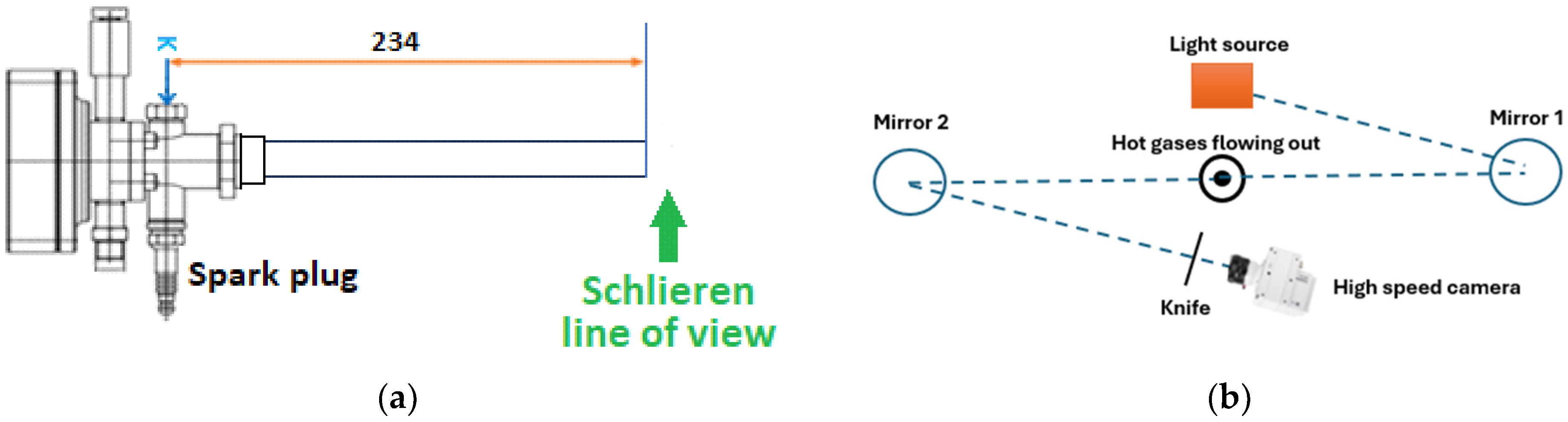
3.2. Schlieren Data Analysis

Figure 9 presents images captured via the high-speed camera positioned downstream of the detonation channel during a pressure-gain combustion cycle. Based on the exhaust pipe’s outer diameter calibration, the spatial resolution yielded 0.357 mm/pixel. As mentioned before, it is important to note that the image quality is somewhat compromised due to the vacuum conditions, which significantly affected how light passes through the chamber. This, combined with the challenges posed by the limited window size of the vacuum chamber, resulted in reduced image clarity. Nonetheless, the key features of the flow dynamics are still discernible.
As flow was established through the exhaust pipe into the vacuum chamber; a recognizable pattern of Mach diamonds can be observed in Figure 9a, marked by the letter “A” just beyond the pipe exit. The Mach diamonds pattern formed due to the rapid expansion of the pressurized mixture jet as it exited the exhaust pipe into a near-vacuum environment. This abrupt expansion, which occurred under near-adiabatic conditions, stemmed from the weak molecular interactions present in the rarefied gas conditions of the vacuum chamber. As a result, there was a notable decrease in temperature, which in turn reduced the speed of sound in the expanding gas.
As high-velocity gas interacted with the slower-moving, lower-pressure ambient air, shock waves were generated due to the sudden deceleration of gas particles. This deceleration was responsible for creating the Mach diamond pattern. The process was influenced by the conservation of energy, which led to an increase in velocity, coupled with the rapid decrease in pressure that occurs during expansion.
As the pressure within the vacuum chamber increased, the flow velocity inside the thruster gradually decreased, leading to an extended residence time for the mixture in the spark plug area. This extended time allows for a sufficient heat transfer to raise the mixture’s temperature above the ignition threshold. At this critical moment, the combustible mixture entering the detonator ignited, resulting in a combustion front that propagated downstream, ultimately reaching the end of the exhaust pipe, as illustrated in Figure 9c (marked by the letter “B”).
For the Schlieren images discussed in this section, the time axis will be aligned with the moment when the combustion products are expelled from the exhaust pipe. This alignment allows for a more precise analysis of the flow structures as they evolve after exiting the detonation channel, giving a clearer view of the dynamics involved in the pressure-gain combustion process. By referencing the images in this way, we ensure a consistent temporal framework for interpreting the complex flow phenomena captured during the experiments.
The leading shock wave typically associated with detonation was not directly discernible due to the ambiguous definition of the speed of sound at such low-pressure levels, which supports the findings referenced in the introduction. Instead, it is more appropriate to reference a leading pressure wave, rather than a shock wave, as the latter more accurately describes higher-pressure conditions that couple with combustion waves to form a detonation. The wave’s influence is evident through the distortion of the Mach diamond pattern, as seen in Figure 9c (marked “A”). The initial converging region, caused by the deceleration and compression of the jet as it interacted with the low-pressure surroundings, disappeared and was replaced with a divergent region, driven by the expansion of the hot, high-pressure jet. The upper part of the first Mach diamond remained convergent but also expanded due to the elevated temperature and pressure, increasing the speed of sound. As a result, pressure waves (labeled “C” in black in Figure 9c) emerged on the outside as the surrounding low-pressure environment reacted to this expansion.
In the subsequent frame shown in Figure 9d, the darker combustion front (labeled “B”) and the leading pressure wave, though not directly visible, can be inferred by the distortion of the first Mach diamond (labeled “A”) as both move downstream. The upper edge of the divergent region in white is pushed further, expanding the first Mach diamond cell due to increased jet pressure. This expansion continues in Figure 9e through Figure 9i. As the cell grew, its shape evolved, with the original upper convergent part giving way to a new cell. Initially, the new cell remained convergent, as shown at 25.58 µs in Figure 9e, but it began straightening by 38.97 µs in Figure 9f as the pressure dropped during expansion. By 51.96 µs in Figure 9g, the upper part of the cell had become fully convergent. When the oblique shock waves converged at their intersection, pressure rose sharply, breaking the flow velocity and creating a Mach disk structure, visible in Figure 9h,i.
From the moment the leading pressure wave interacted with the upper boundary of the first Mach diamond in Figure 9e until the Mach disk formed and was overtaken by the pressure wave in Figure 9g, the wave was observed as a white arc, representing the projection of a spherical pressure wave on the imaging plane.
It is noteworthy that, ahead of the newly forming structure, the flow retained the characteristics of the previous Mach diamonds, indicating that the leading pressure wave acted as a discontinuity that initiated a significant transformation in the flow dynamics. As this pressure wave traveled downstream, the pressure within the original jet dropped considerably due to gas dissipation into the low-pressure environment of the vacuum chamber, creating a rarefaction wave. This rarefaction wave, a region of lower pressure and density, propagated through the flow, altering the pressure and density distribution. Consequently, the older Mach diamond structure disintegrated and was gradually replaced with a new, larger series of Mach diamonds.
Simultaneously, the combustion wave (denoted as “B”) propagated downstream (as seen in Figure 9e,f), with the combustion products visible in black trailing behind it. Due to the low-pressure conditions in the surrounding vacuum chamber, the combustion products dispersed quickly to occupy the available space. As a result, the visibility of the combustion region diminished progressively as it moved forward and expanded (illustrated in Figure 9h,i). This rapid dissipation of combustion products reflects the impact of the low-pressure environment on gas dynamics, where the expansion into a vacuum lead to rapid cooling and dispersion of the gases, further altering the flow structure.
The newly formed pressure waves on the outside of the first Mach diamond began to detach and propagate outward through the rarefied air (indicated as “C” in Figure 9d–i). These waves maintained their straight shape during propagation, in contrast to the spherical shape of the leading pressure wave, suggesting that their origin lies in a straight-line source, which supports the idea that they were generated via the oblique shock waves that define the upper boundary of the first Mach diamond.
As these waves traveled outwards, they interacted and formed a circular arc, marked in black at the top of Figure 9h,i and denoted as “D”. After 77.94 µs, the growth of the new Mach diamond structure halted (Figure 10a, labeled “A”), while the strength of the oblique shocks that formed this structure began to fade, resulting in a weaker, less defined contour (Figure 10b, also marked “A”). Eventually, the size of the first Mach diamond decreased and stabilized after approximately 246.81 µs (Figure 10c, labeled “A”), as the shock wave’s intensity diminished.
During the subsequent time interval, as combustion products were expelled from the thruster, the Mach diamond pattern nearly disappeared (Figure 10d), largely obscured by the hot exhaust flow and the reduction in exhaust velocity as the momentum from the initial ignition was depleted. Additionally, the high temperature of the exhaust increased the local speed of sound. Under atmospheric conditions, this phase would correspond to the reversed flow phase, but in the vacuum, there is insufficient gas outside the exhaust to be entrained.
The Mach diamond structure reappeared at approximately 1545.81 µs after the leading pressure wave exited the exhaust pipe, marked as “A” in Figure 10d. Its shape closely resembles the structure present in the flow before this moment, as seen in Figure 10b, and remained stable for around 2403.15 µs (Figure 10e, “A”). Soon after, the influence of a new leading pressure wave from the next pressure-gain combustion cycle became apparent (Figure 10f), causing the Mach diamonds to increase in size. The new combustion front exited the pipe at 83564.67 µs (Figure 10g, “B”), followed by a distortion of the Mach diamond (Figure 10h, “A”), indicating the start of another cycle.
This new cycle mirrored the previous one, with familiar flow structures marked as “A, B, C and D” in Figure 10i. The observed cycle frequency of 11.97 Hz is close to the spark plug’s specified 10 Hz. The slightly higher frequency is likely due to the spark plug’s wear, causing it to operate at a frequency different from its original specification.

4. Conclusions

The operation of our previously designed and tested PDC breadboard has been validated under vacuum conditions, specifically at an exhaust pressure of 15 mbar inside a vacuum chamber. Several technical modifications were necessary to ensure that the model could sustain pressure-gain combustion cycles in these rarefied conditions. The most significant adjustments included the replacement of the original spark plug with a more powerful one and the reduction in the exhaust pipe diameter from 15 mm to 8 mm.
With these changes in place, the system successfully completed six pressure-gain combustion cycles, as recorded via both pressure sensors and Schlieren imaging. These pressure-gain spikes indicate the presence of six distinct detonation waves. Combustion was initiated at a vacuum level of approximately 103 mbar, and the pressure-gain process persisted for about 0.5 s before an explosion occurred. This explosion was caused by the accumulation of unburned fuel inside the vacuum chamber, a result of the spark plug’s lower ignition frequency, which operates below the engine’s design specification. As a result, more gas products were expelled without being ignited, leading to the buildup of unburned fuel. Schlieren imaging confirms the occurrence of pressure-gain cycles at a frequency of 11.97 Hz. While the leading pressure wave is not directly visible due to the low pressure, its effects on the flow structure can be clearly identified.
Several technical challenges are encountered during the experiments. Maintaining signal integrity was difficult due to elevated noise levels, partially attributed to the wiring connections through the vacuum chamber walls. Additionally, the limited capacity of the vacuum chamber restricted the duration of low-pressure operation, impacting on the overall data collection and the ability to gather more robust results. Unlike the detonation cycles observed under atmospheric conditions, the reverse flow regime was absent under vacuum, as expected.
Further investigation is required to optimize the PDC’s operation under vacuum conditions, but a larger vacuum chamber would be essential to enable more precise and reliable data acquisition.
This study holds considerable significance, particularly considering the limited research currently available on this subject. As the exploration of pressure-gain combustion under vacuum conditions is still an emerging field, findings from this research contribute valuable insights and enhance our understanding. By addressing the technical challenges and complexities associated with this area, this work not only adds to the existing body of knowledge but also paves the way for future advancements in space-based applications. The gaps in the literature highlight the necessity for further investigation, making this study an essential step toward developing more efficient propulsion systems for extraterrestrial environments.

5. Future Work

Based on the findings and technical challenges encountered during the vacuum chamber experiments, several areas for future research are identified to further refine the operation of the PDC for space-based applications.
The current study highlights the need for a more powerful spark plug to achieve stable pressure-gain combustion cycles. One team’s focus will be on the development of an optimized ignition system that offers both reliability and adaptability for a wider range of pressure conditions. This may include testing different types of igniters that are more suitable for rarefied environments, as well as ensuring minimal electromagnetic interference with signal readings.
Noise and electromagnetic interference from the spark plug significantly affect the quality of the pressure data. Future work should involve refining sensor calibration techniques, as well as developing more effective grounding and shielding strategies for sensor wiring in vacuum conditions. This will improve the accuracy of pressure-gain readings and reduce ambiguity in interpreting the signals.
One of the key limitations of this study was the restricted operational time at low pressure, due to the limited capacity of the vacuum chamber. Conducting future experiments at a larger vacuum facility would enable prolonged operation and better control over pressure conditions. This would allow for more thorough data collection over extended pressure-gain combustion cycles and a more accurate analysis of detonation dynamics.
While six distinct pressure-gain combustion cycles were achieved in this study, future work should focus on examining the long-term behavior of the PDC under vacuum conditions. This includes investigating whether stable detonation can be sustained over a larger number of cycles and exploring any potential degradation in performance or material wear during extended operation.
The research presented here significantly contributes to bridging the gap between ground-based experiments and the eventual development of a PDC for space applications. Future work should continue refining the design of the PDC to operate in extreme environments, focusing on optimizing fuel efficiency, reliability, and scalability. Ultimately, the goal is to advance the technology toward a fully operational space propulsion system capable of delivering performance benefits in space. By addressing these challenges, the research will bring PDC technology closer to achieving a functional space-based propulsion system capable of utilizing pressure-gain combustion for more efficient spacecraft propulsion.

Author Contributions

Software, A.V.C., M.G. and I.P.; writing—original draft preparation, A.V.C.; conceptualization, A.V.C., I.P., T.C. and G.U.; methodology, A.V.C., G.I.V. and I.P.; validation, A.V.C. and M.G.; investigation, A.V.C., M.G., G.I.V., I.P., T.C., G.U. and D.E.C.; data curation, T.C.; visualization, G.I.V., M.G. and D.E.C.; supervision, A.V.C., I.P. and T.C.; project administration, I.P.; funding acquisition, I.P. and A.V.C. All authors have read and agreed to the published version of the manuscript.

Funding

This work was funded by the European Space Agency through contract no. 4000131302/20/NL/MG—“Pulsed Detonation Thruster” (PDT). The experimental work was carried out at the Testing and Experimentation Centre for Space and Security (TESS) of the Romania National Research and Development Institute for Gas Turbines—COMOTI.

Informed Consent Statement

Not applicable.

Data Availability Statement

Data are contained within the article.

Acknowledgments

The authors wish to extend their thanks for valuable guidance and support to Guillermo Paniagua of Purdue University and Bayindir Saracoglu of the “Von Karman” Institute for Fluid Dynamics.

Conflicts of Interest

The authors declare no conflicts of interest.

References

  1. Miele, A.; Wang, T. Optimal trajectories for Earth-to-Mars flight. J. Optim. Theory Appl. 1997, 95, 467–499. [Google Scholar] [CrossRef]
  2. Bolle, A.; Circi, C.; Corrao, G. Optimal Mars transfers for small payload transportation. Celest. Mech. Dyn. Astron. 2010, 106, 183–196. [Google Scholar] [CrossRef]
  3. Chen, L.; Li, J. Optimization of Earth-Mars transfer trajectories with launch constraints. Astrophys. Space Sci. 2022, 367, 12. [Google Scholar] [CrossRef]
  4. Oleson, S.R.; Burke, L.M.; Mason, L.S.; Turnbull, E.R.; McCarty, S.; Colozza, A.J.; Fittje, J.E.; Yim, J.T.; Smith, M.; Packard, T.W.; et al. Compass Final Report: Nuclear Electric Propulsion (NEP)-Chemical Vehicle 1.2. 2021; No. CD-2020-181. Available online: https://ntrs.nasa.gov/citations/20210017131 (accessed on 2 September 2024).
  5. Burke, L.M.; Oleson, S.R.; Zoloty, Z.C.; Smith, D.; Havens, M. Combined 1-MW Solar Electric and Chemical Propulsion for Crewed Mars Missions. In Proceedings of the ASCEND Conference, Las Vegas, NV, USA, 23–25 October 2023. AIAA 2023-4789. [Google Scholar]
  6. Cuciumita, C.F.; Cuciuc, T.; Porumbel, I. Evaluation of the Cycle Averaged Performances of a Pulsed Detonation Engine Based on Thermodynamic Cycle Computations. In Proceedings of the ASME Turbo Expo 2016: Turbomachinery Technical Conference and Exposition, Seoul, Republic of Korea, 13–17 June 2016. GT2016-57310. [Google Scholar]
  7. Innovative Propulsion Cross Cutting Initiative. Available online: https://indico.esa.int/event/441/overview (accessed on 2 September 2024).
  8. Paschen, F. Über die zum Funkenübergang in Luft, Wasserstoff und Kohlensäure bei verschiedenen Drucken erforderliche Potentialdifferenz. Annalen der Physik 1889, 273, 69–96. [Google Scholar] [CrossRef]
  9. Loveless, A.M.; Garner, A.L. A universal theory for gas breakdown from microscale to the classical Paschen law. Phys. Plasmas 2017, 24, 113522. [Google Scholar] [CrossRef]
  10. Liang, X.; Huang, X.; Deng, J.; Jin, S.; Li, L. Spark Ignition Characteristics of Hydrogen Under Ar-O2 Atmosphere. In Proceedings of China SAE Congress 2020: Selected Papers; Springer: Singapore, 2022; pp. 1027–1039. [Google Scholar]
  11. Kailasanath, K. Review of Propulsion Applications of Detonation Waves. AIAA J. 2000, 38, 1698–1708. [Google Scholar] [CrossRef]
  12. Wolanski, P. Detonative propulsion. Proc. Combust. Inst. 2013, 34, 125–158. [Google Scholar] [CrossRef]
  13. Shang, J.; Hu, G.; Wang, Q.; Xiang, G.; Zhao, W. Progress of Experimental Studies on Oblique Detonation Waves Induced by Hyper-Velocity Projectiles. Aerospace 2024, 11, 715. [Google Scholar] [CrossRef]
  14. Powers, J.M. Oblique detonations: Theory and propulsion applications. In Combustion in High-Speed Flows; Springer: Dordrecht, The Netherlands, 1994; pp. 345–371. [Google Scholar]
  15. Roy, G.; Frolov, S.; Borisov, A.; Netzer, D. Pulse detonation propulsion: Challenges, current status and future perspective. Prog. Energy Combust. Sci. 2004, 30, 545–672. [Google Scholar] [CrossRef]
  16. Sorin, R.; Zitoun, R.; Desbordes, D. Optimization of the deflagration to detonation transition: Reduction of length and time of transition. Shock Waves 2006, 15, 137–145. [Google Scholar] [CrossRef]
  17. Wilson, J.; Wernet, M.P.; Paxson, D.E. Vortex Rings Generated by a Shrouded Hartmann–Sprenger Tube. AIAA J. 2006, 44, 2706–2718. [Google Scholar] [CrossRef]
  18. Knox, B.; Forliti, D.; Stevens, C.; Hoke, J.; Schauer, F. A comparison of fluidic and physical obstacles for deflagration-to-detonation transition. In Proceedings of the 49th AIAA Aerospace Sciences Meeting Including the New Horizons Forum and Aerospace Exposition, Orlando, FL, USA, 4–7 January 2011; p. 587. [Google Scholar]
  19. Frolov, S.M.; Smetanyuk, V.A.; Aksenov, V.S.; Koval’, A.S. Deflagration-to-Detonation Transition in Crossedflow Fast Jets of Propellant Components. In Doklady Physical Chemistry; Springer: Berlin/Heidelberg, Germany, 2017; Volume 476, pp. 153–156. [Google Scholar]
  20. Soni, S.K.; Kaushal, R. Review of the parameters of obstacles affecting deflagration to detonation transition (DDT) for pulse detonation engine application. AIP Conf. Proc. 2021, 2341, 030024. [Google Scholar]
  21. Zhang, B. Enhancing detonation propulsion with jet in cross-flow: A comprehensive review. Prog. Aerosp. Sci. 2024, 147, 101020. [Google Scholar] [CrossRef]
  22. Buyakofu, V.; Matsuoka, K.; Matsuyama, K.; Kawasaki, A.; Watanabe, H.; Itouyama, N.; Goto, K.; Ishihara, K.; Noda, T.; Kasahara, J.; et al. Flight demonstration of pulse detonation engine using sounding rocket S-520-31 in space. J. Spacecr. Rocket. 2023, 60, 181–189. [Google Scholar] [CrossRef]
  23. Goto, K.; Matsuoka, K.; Matsuyama, K.; Kawasaki, A.; Watanabe, H.; Itouyama, N.; Ishihara, K.; Buyakofu, V.; Noda, T.; Kasahara, J.; et al. Space flight demonstration of rotating detonation engine using sounding rocket S-520-31. J. Spacecr. Rocket. 2023, 60, 273–285. [Google Scholar] [CrossRef]
  24. Cooper, M.; Jackson, S.; Austin, J.; Winterberger, E.; Shepherd, J.E. Direct Experimental Impulse Measurements for Detonations and Deflagrations. J. Propuls. Power 2002, 18, 1033. [Google Scholar] [CrossRef]
  25. Cooper, M.; Jackson, S.; Shepherd, J.E. Effect of Deflagration-to-Detonation Transition on Pulse Detonation Engine Impulse; GALCIT Report FM00-3; Explosion Dynamics Laboratory, Graduate Aeronautical Laboratories, California Institute of Technology: Pasadena, CA, USA, 2000. [Google Scholar]
  26. Zhdan, S.A. Structure of Detonation Waves in a Vacuum with Propellant Particles. In Dinamic Aspects of Explosion Phenomena; Progress in Astronautics and Aeronautics; Kuhl, A.L., Leyer, J.-C., Sirignano, W.A., Eds.; AIAA Inc.: New York, NY, USA, 1991; Volume 154, pp. 252–262. [Google Scholar]
  27. Zhdan, S.A.; Prokhorov, E.S. Initiation of detonation in vacuum suspensions of RDX particles. Combust. Explos. Shock Waves 1998, 34, 426–432. [Google Scholar] [CrossRef]
  28. Pinaev, A.V. Detonation of Secondary Explosives in a Vacuum Suspension. Combust. Explos. Shock Waves 2001, 37, 214–218. [Google Scholar] [CrossRef]
  29. Li, X.; Cheng, Y.F.; Zhu, S.J.; Chen, Z.H.; Shen, Z.W. Effects of vacuum degree on the detonation characteristics and energy release laws of RDX explosive. Vacuum 2024, 225, 113270. [Google Scholar] [CrossRef]
  30. Morris, C.I. Numerical Modeling on Single-Pulse Gas Dynamics and Performance of Pulse Detonation Rocket Engines. J. Propuls. Power 2005, 21, 527–538. [Google Scholar] [CrossRef]
  31. Yan, Y.; Fan, W.; Wang, K.; Zhu, X.D.; Mu, Y. Experimental investigations on pulse detonation rocket engine with various injectors and nozzles. Acta Astronaut 2011, 69, 39–47. [Google Scholar] [CrossRef]
  32. Wang, K.; Fan, W.; Lu, W.; Zhang, Q.; Chen, F.; Yan, C.; Xia, Q. Propulsive performance of a pulse detonation rocket engine without the purge process. Energy 2015, 79, 228–234. [Google Scholar] [CrossRef]
  33. Alam, N.; Sharma, K.K.; Pandey, K.M. Combustion characteristics of hydrogen-air mixture in pulse detonation engines. J. Mech. Sci. Technol. 2019, 33, 2451–2457. [Google Scholar] [CrossRef]
  34. Cojocea, A.V.; Cuciuc, T.; Porumbel, I.; Gall, M.; Gherman, B.; Crunţeanu, D.E. Experimental Investigations of Hydrogen Fuelled Pulsed Detonation Combustor. In Turbo Expo: Power for Land, Sea, and Air; American Society of Mechanical Engineers: New York, NY, USA, 2022; Volume 86007, p. V03BT04A020. [Google Scholar]
  35. Vrabie, G.I.; Asoltanei, D.; Cojocea, A.V.; Gall, M.; Cuciuc, T. Experimental Comparison for Different Oxidizers in Hydrogen Fuelled Pulsed Detonation Combustor. TURBO J. 2022, X, 35–49. [Google Scholar]
  36. Cojocea, A.V.; Porumbel, I.; Gall, M.; Cuciuc, T. Experimental Thrust and Specific Impulse Analysis of Pulsed Detonation Combustor. Appl. Sci. 2024, 14, 5999. [Google Scholar] [CrossRef]
  37. Bogoi, A.; Cuciuc, T.; Cojocea, A.V.; Gall, M.; Porumbel, I.; Hrițcu, C.E. Experimental Pressure Gain Analysis of Pulsed Detonation Engine. Aerospace 2024, 11, 465. [Google Scholar] [CrossRef]
  38. Cojocea, A.V.; Porumbel, I.; Gall, M.; Cuciuc, T. Experimental Investigations on the Impact of Hydrogen Injection Apertures in Pulsed Detonation Combustor. Energies 2024, 17, 4918. [Google Scholar] [CrossRef]
  39. Settles, G.S. Schlieren and Shadowgraph Techniques: Visualizing Phenomena in Transparent Media; Springer Science & Business Media: Berlin/Heidelberg, Germany, 2001. [Google Scholar]
Figure 1. (a) PDC diagram [37]: I—premixing section, II—ignition section, III—detonation channel, 1—oxidizer inlet, 2—end wall, 3—fuel inlet, 4—air passage window, 5—perforated plate, 6—vortex generation chamber, 7—diaphragm, and 8—Hartmann–Sprenger resonators; (b) PDC prototype inside the vacuum chamber.
Technologies 12 00252 g001
Figure 2. Regular automobile spark plug supply power under vacuum conditions.
Technologies 12 00252 g002
Figure 3. PDC prototype inside the vacuum chamber.
Technologies 12 00252 g003
Figure 4. Instrumentation diagram of the experimental setup. K indicates the position of the pressure sensors of the detonation channel, and the green arrow indicates the line of view for the Schlieren visualizations: (a) side view; (b) top view.
Technologies 12 00252 g004
Figure 5. Pressure signals during the full PDC vacuum operation test: (a) pressure inside the PDC; (b) pressure in the vacuum chamber; (c) background noise detail by pressure sensor in the vacuum chamber; (d) cold flow detail of pressure in the vacuum chamber; and (e) ignition detail in the vacuum chamber.
Technologies 12 00252 g005aTechnologies 12 00252 g005b
Figure 6. Pressure signals during PDC ignition.
Technologies 12 00252 g006
Figure 7. Pressure signals during PDC operation.
Technologies 12 00252 g007
Figure 8. Pressure signals during the explosion.
Technologies 12 00252 g008
Figure 9. Schlieren images of the flow exiting the PDC around the cycle ignition moment under vacuum conditions; (a) −1.953 μs; (b) −12.99 μs; (c) 0.00 μs; (d) 12.99 μs; (e) 25.58 μs; (f) 38.97 μs; (g) 51.96 μs; (h) 64.95 μs; and (i) 77.94 μs.
Technologies 12 00252 g009aTechnologies 12 00252 g009b
Figure 10. Schlieren images of of the flow exiting the PDC under vacuum during later stages: (a) 90.93 μs; (b) 129.90 μs; (c) 246.81 μs; (d) 1545.81 μs; (e) 3948.96 μs; (f) 83447.76 μs; (g) 83564.67 μs; (h) 83577.66 μs; and (i) 83655.60 μs.
Technologies 12 00252 g010aTechnologies 12 00252 g010b
Disclaimer/Publisher’s Note: The statements, opinions and data contained in all publications are solely those of the individual author(s) and contributor(s) and not of MDPI and/or the editor(s). MDPI and/or the editor(s) disclaim responsibility for any injury to people or property resulting from any ideas, methods, instructions or products referred to in the content.

