1. Introduction
Bending is a forming operation where the curvature of one or more sections of a workpiece is changed [
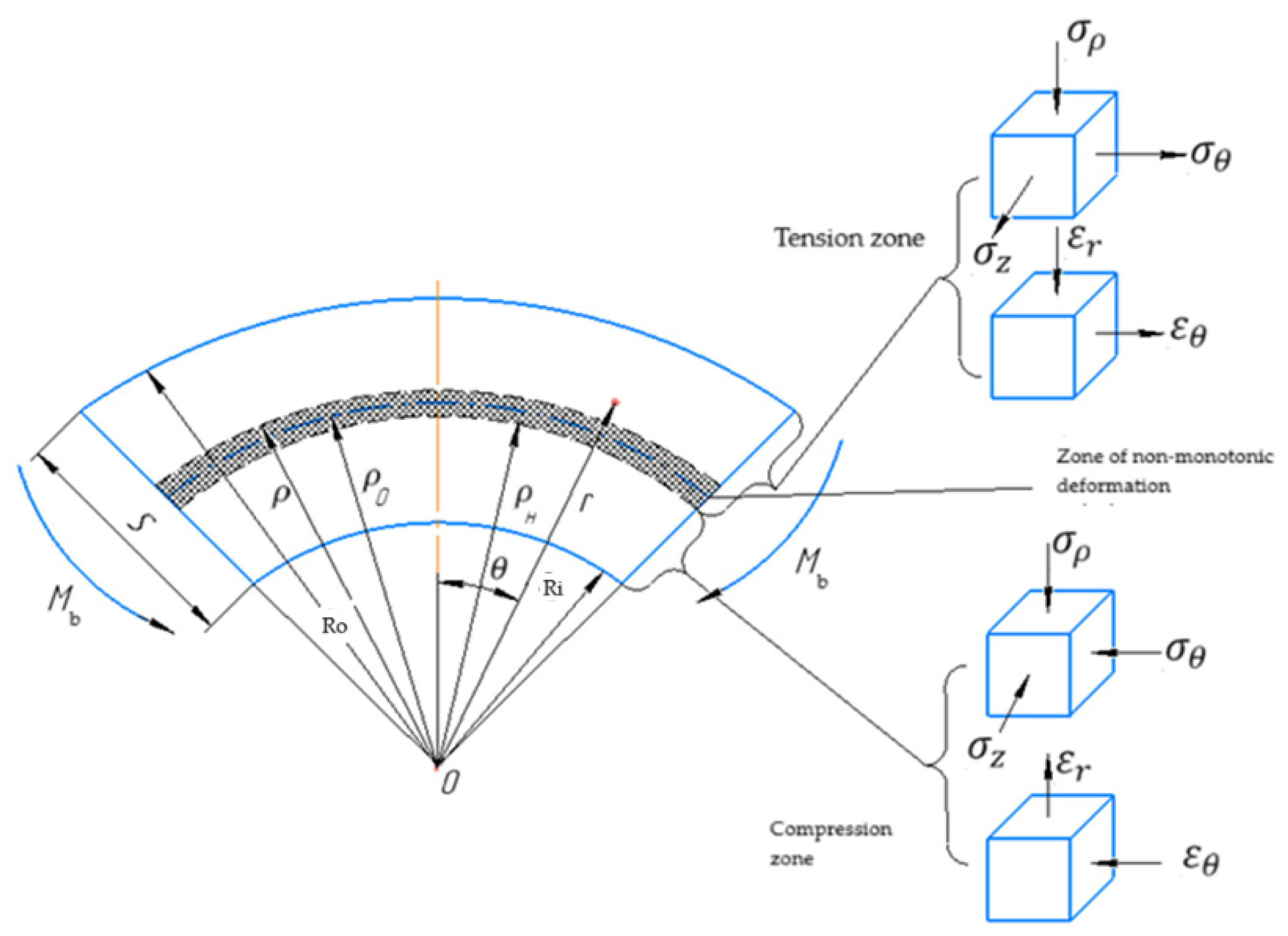
1]. The features of the bending process are determined by factors such as the presence of principal strains and tangential stresses along the thickness of two zones with different signs, the non-monotonicity of the deformation process across the thickness of the workpiece, the presence of a neutral layer according to final tangential deformation, the need to consider strain hardening, changes in the thickness of the bent sheet, and the distortion of the cross-section.
The performance properties of the finished parts obtained by stamping are largely determined by the characteristics of the initial sheet billet obtained by rolling [
2,
3,
4,
5]. When selecting the characteristics of the sheet billet, the choice is traditionally made based on requirements regarding the properties of the part and the ability of the billet to shape change in sheet-forming operations.
In manufacturing, a variety of bending processes are applied to different materials, which can be classified by their strain-hardening characteristics [
6,
7,
8,
9,
10,
11], specifically the yield stress
σ0.2-to-ultimate strength
σb ratio (
Figure 1a). Materials with a high ratio exhibit a poor strain-hardening capacity, making them less resistant to plastic deformation under bending. In contrast, materials with a low yield-to-strength ratio undergo significant strain hardening, accommodating higher stress levels. The materials exhibit great variability in their strain-hardening responses, which affects their formability and bending performance.
Many sheet materials, especially aluminum alloys, exhibit the anisotropy of plastic properties (
Figure 1b, where
µij is a transverse strain coefficient). These papers [
6,
7,
8,
9,
10,
11] show that anisotropy affects the magnitude of stresses and strains, as well as the nature of their distribution during sheet bending. This indicates the need to consider both the strain-hardening and plastic anisotropy of properties during bending.
Of course, the bending behavior of sheet materials is also influenced by microstructural characteristics, including the grain size, homogeneity, and the presence of cast defects, inclusions, or microsegregation. Such factors can act as structural notches, which may reduce ductility and impact the minimum achievable bend radius [
12]. However, for the purposes of analyzing the stress–strain state in bending, in this study, we assumed a homogeneous, defect-free material structure, allowing us to focus on the intrinsic bending mechanics without the added complexity of structural irregularities.
When analyzing the processes of bending metal sheets in a cold state, it is necessary to consider strain hardening, i.e., the variability in stress intensity values
across thickness. This is due to the non-monotonic nature of the deformation process across thickness. Deformation proceeds monotonically at
, where the material particles at all the previous stages of the bending process shorten in the tangential direction. Deformation also proceeds monotonically at
, where the material particles at all the previous stages of the bending process elongate in the tangential direction. At
, deformation cannot be considered monotonic since the material particles observed at this moment at these radii at the beginning of the bending process shorten in the tangential direction and then begin to elongate. Thus, it is possible to distinguish the radius
of the neutral layer according to the final deformation of the material fiber, represented by a change in length, in the zone of non-monotonic deformation
; for such a layer, the material particles are equal in size to their initial values at this moment. At the very beginning of the bending process, the particles in this layer shorten in the tangential direction and elongate in the radial direction, and then begin to elongate in the tangential direction and shorten in the radial direction. At this moment, again, they take the shape they had before deformation. The values of the radii of the neutral layer under stress
and final deformation
conditions are necessary to calculate the stress–strain state, force conditions, and ultimate deformation capabilities of the workpiece during bending. The difficulty in calculating the values of
lies in the need to consider the change in thickness of the bent sheet (as practice shows, the sheet usually thins slightly during bending), strain hardening, and the anisotropy of the plastic properties of the workpiece [
13,
14].
The analysis of papers [
1,
12,
15,
16,
17,
18,
19,
20,
21,
22] dedicated to the theory of sheet bending shows that, to date, there are no studies that take into account the combined influence of the anisotropy of the workpiece, its hardening during the bending process, and the presence of a non-monotonic deformation zone. Additionally, there is a lack of research dedicated to increasing the zone of plastic deformations in areas of free bending and subsequently reducing them when the workpiece is drawn into the die and the material, bent around the punch radius, is unloaded. However, these factors are critically important for designing the geometry, dimensions, and die tool design.
A large number of computational experiments were conducted using the finite element method, the results of which are presented in the form of diagrams for practical use in the design of bending dies. A similar approach to die design is presented in [
23,
24]. The final shape of the workpiece is specified, and the finite element method is used to calculate the distribution of forces, which are used to find the unloading displacements in accordance with the well-known theorem of A.A. Ilyushin [
18].
Papers [
25,
26,
27,
28,
29,
30,
31,
32,
33,
34,
35] also highlight the need for more accurate predictions of workpiece behavior during bending. For this purpose, analytical models that could consider various process parameters were developed. These models consider continuous changes in material properties throughout the entire process and have been compared with the experimental results, which show that this model can provide high prediction accuracy. The analysis of the results in these articles demonstrated that the developed models, which account for the non-linear characteristics of the material and its behavior during deformation, show better alignment with real process conditions.
The influence of various parameters such as the sheet thickness, applied force, and geometrical dimensions of the main parts of the die tooling was evaluated in [
36,
37,
38,
39,
40]. The various bending models were obtained and analyzed by using analytical formulas and finite element modeling.
Thus, existing approaches and models for sheet-bending processes lack comprehensive consideration of material plastic anisotropy, strain hardening, and non-monotonic deformation zones. These factors are critical for designing die tools and process parameters, but they have not been adequately addressed in the previous studies. The proposed model in this paper simultaneously accounts for the above-mentioned factors, providing more accurate predictions of material behavior during bending. This approach enhances the design process by allowing for more precise control over the final shape and dimensions of the part.
2. Problem Statement
Let us consider the case of circular bending of an anisotropic reinforcing strip with width
B and a thickness
with moment
Mb (
Figure 2), taking into account its thinning. Let us suggest that thickness
is varied between 0.5 mm and 10 mm. This range includes most industrial applications [
2,
41]. Since moment-induced bending is considered, there is no contact between the strip and the tool in the plastic deformation zone, eliminating the need to account for friction effects.
We will make the following assumptions when analyzing the final circular bending of a sheet: there is a plane strain state, ; the outer (convex) surface is strictly concentric; the hypothesis of the plane sections is valid; tangential stresses are absent; the incompressibility condition holds true. The material of the workpiece is isotropically hardening, orthotropic, and the material properties are the same in compression and tension. We will consider only cases where the principal axes of the anisotropy coincide with the principal axes of stress, i.e., the bend edge is either along or perpendicular to the rolling direction. We assume that the chosen hardening function remains valid throughout the entire thickness of the bent sheet.
We will use the linearized plasticity criterion proposed in [
21] to account for the anisotropy of the properties of the bent sheet billet. This criterion is based on a quadratic yield surface, commonly used in metal forming analyses for its balance between accuracy and analytical simplicity. The linearized form facilitates the derivation of analytical equations while the Lode coefficient is employed to capture the curvature of the yield surface, ensuring the model’s relevance to materials with non-linear yield behavior:
where the “+” sign corresponds to the tension zone (r >
); the “−” sign corresponds to the compression zone (r <
;
is the yield stress of the blank material;
is the modified Lode coefficient, which, as shown in [
41], is the same for both the tension and compression zones and depends only on the anisotropy. For a plane strain state, if the rolling direction is perpendicular to the bend edge, then
and if the rolling direction is parallel to the bend edge, then
Here,
are the transverse strain coefficients for the transverse and rolling directions of the original sheet billet. The transverse strain coefficients show the ratio of transverse strain to longitudinal strain in the uniaxial tension of the specimen [
1].
The functional dependence of the transverse strain coefficients
on the angle
with respect to the rolling direction is introduced [
21] to generalize the model for cases where the principal axes of the anisotropy are oriented at angles other than parallel or perpendicular to the bend edge:
where the transverse strain coefficients
and the anisotropy coefficients
are related by the following dependence
;
(
) are the coefficients at a 45° angle to the rolling direction.
To account for hardening, we apply a power-law approximation of the hardening curve, as this model effectively represents the non-linear stress–strain behavior of most metals and alloys, particularly capturing the elastic strain level that marks the onset of the plastic deformation, which is essential for accuracy in the bending processes involving small plastic strains [
1]:
where
is the plastic strain intensity;
is the elastic strain level at which the yield strength is reached;
A and
n are the hardening constants.
Let us write the expression for the strain intensity considering the incompressibility condition [
21]:
where the direction of the principal stress axes and anisotropy 1 coincides with the rolling direction, and 2 coincides with the transverse direction.
We can write Expression (5) as follows:
where
K is a coefficient that accounts for the stress–strain state scheme and the orientation of the principal anisotropy axes relative to the principal stress axes.
Given that the rolling direction is perpendicular to the bend edge (where direction 1 coincides with the tangential direction, direction 2 with the bend edge, and direction 3 with the radial direction), and considering the plane strain condition
, we obtain:
and if the rolling direction is parallel to the bend edge (where direction 1 coincides with the bend edge, direction 2 with the tangential direction, and direction 3 with the radial direction):
Thus, the value of coefficient
K coincides with the modified Lode’s coefficient
β (2) and (3), then we will write Equation (6) as:
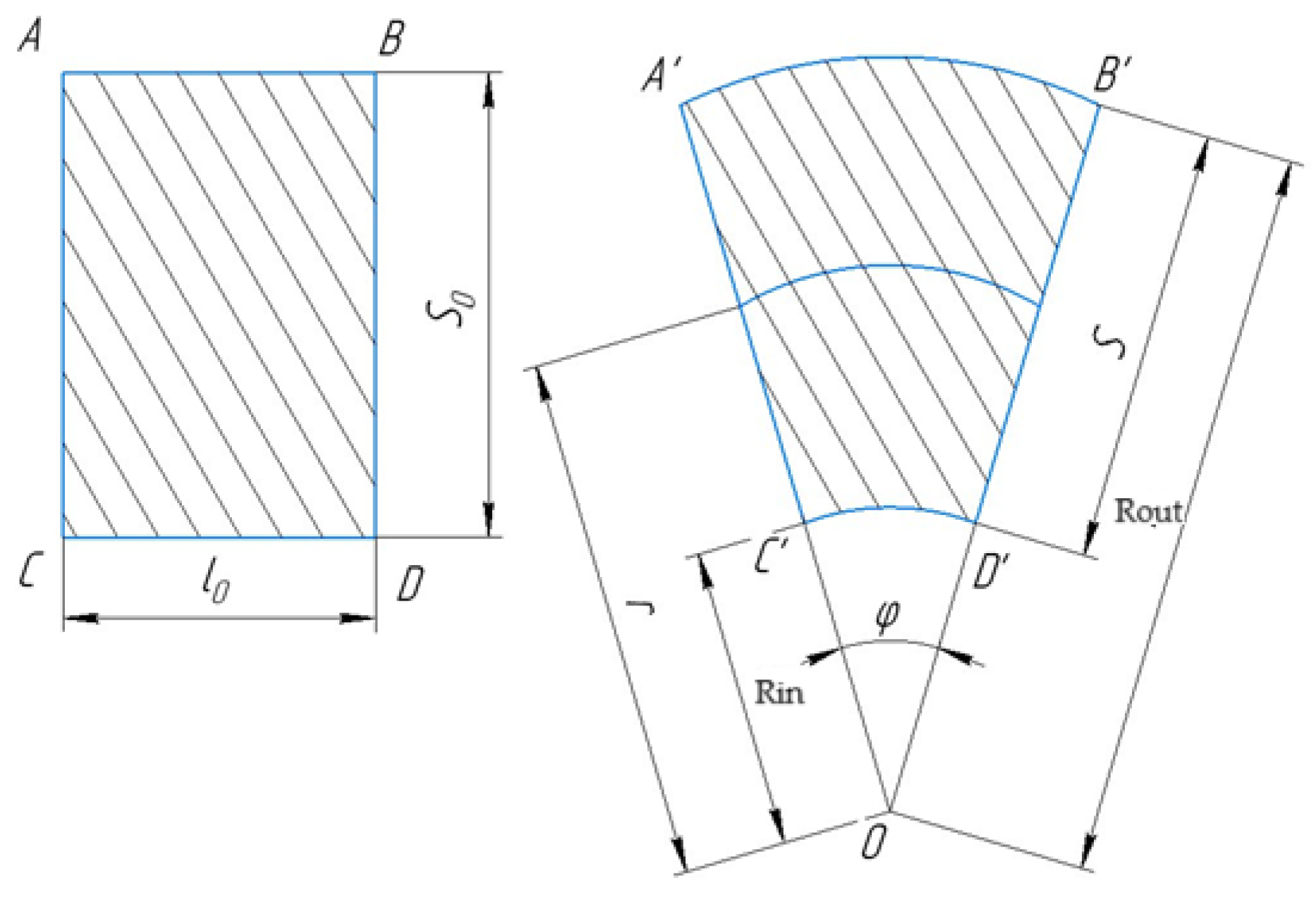
Let us consider the cross-section of the bending sheet in a plane perpendicular to the bend edge before and after deformation (see
Figure 3). Let
A’B’C’D’ be the cross-section perpendicular to the bend edge of the considered particle of the bending sheet, bounded by two planes
A’C’ and
B’D’ that pass through the common centers of curvature
O for the outer surface (
A’B’) and the inner surface (
C’D’). This cross-section was a rectangle with sides
ABCD before the deformation:
Since the deformation in the direction of the bending edge is zero
and the volume does not change, the area of the section under consideration remains unchanged during deformation:
where
is the angle bounding the circular element under consideration.
Considering that the thickness of the sheet
s in the considered bending deformation stage is equal to:
we obtain:
Solving the system of two Equations (11) and (12) for the variables in the bending process of curvature radii
, we obtain:
Let us use the fundamental relationship of the theory of the circular bending of sheets, derived from purely geometric (kinematic) considerations [
1,
42]:
Equation (15) links all the geometric parameters of the circular bending problem but does not account for the mechanical (force-related) aspects, including the sheet properties and their anisotropy.
3. Calculation of Stresses, Deformations, and Geometrical Parameters
Next, we consider the distribution of the strain intensity along the thickness of the bent blank, specifically on the convex (outer), concave (inner), and stress-neutral surfaces [
26]. We obtain the expression for strain in the tangential direction at
on the convex surface (
Figure 3):
Then, we obtain by considering (9):
When
is on the concave surface
and
Similarly, we obtain the expression of strain intensity at
:
Let us differentiate both Equations (17) and (29) with respect to
and take into account Equations (12)–(14), as well as the equations obtained by differentiating Equations (13) and (14) with respect to
. After a series of simple transformations, we obtain:
We can write, by using Equations (17), (19) and (20), the following:
We have, by substituting Expressions (22) and (23) into Equation (21), the following:
We obtain, by dividing the second Equation (24) by the first one, and after performing straightforward algebraic transformations, the following:
Equation (25), unlike Equation (15), already accounts for the plastic anisotropy. However, this equation alone is not sufficient to determine all the necessary geometric parameters for the problem of circular bending of a sheet, as it relates three variables in the deformation process:
The functional relationship between two of these quantities and the third, which could be considered as the argument, cannot be determined independently of the force characteristics of the phenomenon, as well as the material’s ability to resist plastic deformation and the mechanical properties of the material.
Let us write the equilibrium condition for the case of circular bending:
Then, considering the plasticity Condition (1) for the compression zone (
Figure 2) at
, we have:
and for the tensile zone at
:
Since the length of the neutral layer with radius
by the final deformation did not decrease and did not increase in the tangential direction, then
Then, taking (29) into account, we write the equation for strain intensity at
:
for
:
Differentiating
with respect to
r, we obtain for
:
and if
:
Let us write, by substituting Equations (32) and (33) into Equation (27), the following:
and into Equation (28):
We obtain, by integrating Equations (34)–(36) and noticing that at
and at
, i.e., on surfaces
free from external loads (for circular bending), the following:
where
C is the integration constant.
Knowing the distribution of radial stresses over the thickness of the bent billet, the tangential stress can be determined from the plasticity Condition (1) .
Noticing that
does not undergo a gap at
and at
and that
let us equate the right parts of Equations (37) and (38) at
and the right parts of Equations (38) and (39) at
:
Let us solve the left side of Equation (41) and substitute
C from Equation (42) into the right side by using the properties of the definite integral:
As a result, we obtain an equation linking the three variables in the deformation process, namely
,
, and
:
Equation (44) is an additional requirement for solving Equation (25), which includes the anisotropy indices. That is, the functional relationship between , and, depends on the anisotropy.
Let us substitute the hardening Function (4) into (44). We obtain, after integration and transformations, the following:
Thus, taking one of the variables , as an independent argument and the other two variables as unknowns, then solving together the system of two Equations (25) and (45), we can determine the functional dependences of these two unknown variables on the variable taken as an argument.
Let be considered as the independent variable, varying within the specific limits for the given material. The variables and are to be treated as the desired functions of the independent variable . The values of and , corresponding to any value of within the given limits can be obtained by solving the system of Equations (25) and (45) simultaneously. In this case, a table of values for , , and can be compiled. Any possible combination of these quantities for the given material can be determined by using this table.
Let us show that for any such combination, the values of the ratios
, and
can be computed. We obtain the following relationships from Equations (17), (19) and (22):
Further, we note that denoting (29) can reduce the Equation (10) to the form:
After substituting the Expressions (43) into the left part of this equation and algebraic reductions, we obtain:
We can reduce Equation (46) to the form considering Equation (48):
We obtain, by subtracting the equality (49) from the equality (50), taking (11) into account and after simple algebraic transformations, the following:
5. Experimental Verification of the Developed Bending Process Model
An experimental study of strain distribution along the thickness of the bent billet was carried out in order to verify the developed theoretical provisions of the circular bending process.
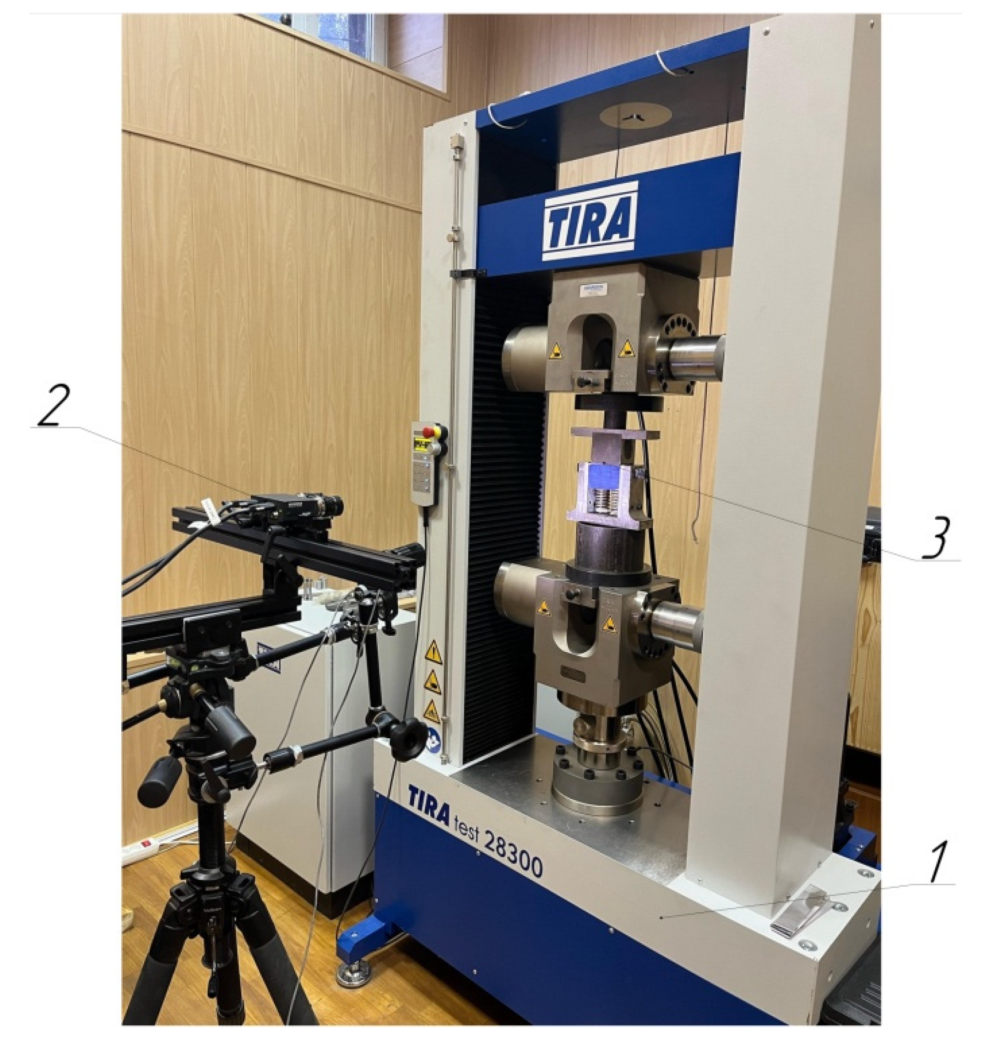
The TIRAtest 28300 (TIRA GmbH, Schalkau, Germany) universal testing machine was used as the deforming equipment. The traverse speed on the testing machine was set to 5 mm/min. A single-operation die for two-angle bending was designed and manufactured as the experimental tooling (
Figure 4). The working elements of the die were made of U10 steel. The sample was secured to punch 3 with bolt 6 to approximate a plane strain state during bending. The fixation area, which remains undeformed, is positioned away from the plastic deformation zone to prevent any influence on the measured results. The tests were conducted without applying lubricant. For the analysis of the deformed state, the Vic-2D (Correlated Solution Ltd., Irmo, SC, USA) non-contact strain measurement system was used. Its operation is based on the digital image correlation technique. The overall view of the test setup is shown in
Figure 5.
The experiment was conducted on hot-rolled billets that were 6.0 mm thick and made of aluminum alloy 8011A: (Al 98.07–98.36%; Si 0.7–0.8%; Fe 0.7–0.8%; Cu 0.03–0.06%; Mn 0.05%; Mg 0.02–0.08%; Cr 0.03%; Zn 0.05%; Ti 0.05%; Be 0.0001% [
43]). Tensile tests were conducted on samples cut both along and across the rolling direction to determine the mechanical properties of the billets. The sample dimensions and test parameters conformed to ISO 6892-1 [
44,
45]. The method described in [
41] was used to determine the anisotropy indices. The tests were performed using the TIRAtest 28300 universal testing machine. The test results are presented in
Table 1.
Samples with dimensions of 125 × 60 mm were prepared, with the long side aligned with the rolling direction. A speckle pattern, with dot sizes of 0.18 mm, was applied to one of the larger ends using special stencils. The optimal dot size, considering the measurement error of this strain measurement method, was established in [
46].
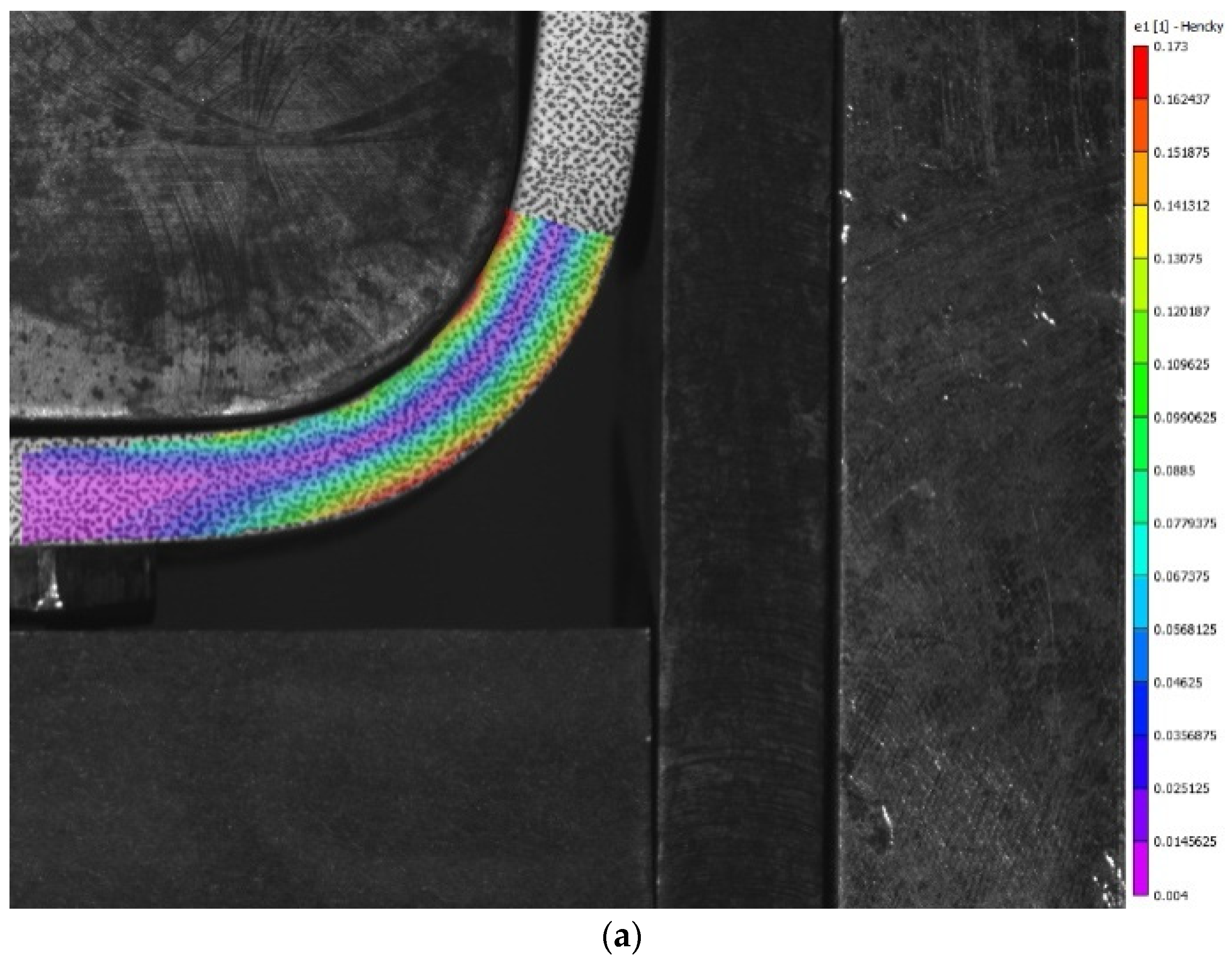
The Vic-2D system was used to obtain distribution patterns of tangential and radial strains, as well as the strain intensity (
Figure 6) after the tests. The resulting deformed state fully corresponds to the classical theory of bending: near the inner radius, negative tangential strains are observed, indicating compression of fibers in this region, while positive strains, indicating fiber stretching, are present at the outer radius. The opposite pattern is observed for radial deformations.
Based on the experimental data and the results of the calculations using the developed bending process model, the strain distribution across the thickness of the billet was plotted for
(
Figure 7). Verification of the mathematical model was performed by comparing the magnitude and distribution of the strains across the billet thickness, as an experimental determination of the radius of the neutral stress or the final deformation layers was impractical due to the limitations in measuring within the material’s thickness and the inaccuracies introduced by edge roughness and the distortion during bending.
The error in the calculations using the developed mathematical model is no more than 5–7%, as seen in
Figure 7. The largest discrepancy between the calculated and experimental data is observed for the radial strains in the tensile zone. This discrepancy can be attributed to the difficulty in achieving ideal deformation at the edge of the billet during the experiment.
6. Numerical Example and Discussion
We will calculate the process according to the parameters given in the previous paragraph by using the developed mathematical model. All the key process parameters , , and will be considered as functions of relative bending radius .
It was found that the strain intensity increases as the relative bending radius decreases (at
) based on the calculations (
Figure 8). The strain intensity on the inner (concave) surface is greater than on the outer (convex) surface, and this difference increases as
decreases. The strain intensity on the neutral surface in terms of stress is negligibly small for
but sharply increases for
, becoming comparable to the strains on the outer and inner surfaces.
The results of the calculations for the geometric parameters of the bending process are presented in
Figure 9. From
Figure 9a, it can be seen that the radii of the neutral surfaces are in terms of the stress and final strain deformation as
decreases. At the same time,
slightly differ for
but
begins to decrease sharply for
. Thus, the neutral surface, in terms of stress, shifts towards the inner (concave) surface, leading to a reduction in the thickness of the workpiece. From
Figure 9b, it can be seen that the thinning of the workpiece increases with the reduction in the bending radius
Thinning can be neglected for
but for
thinning reaches several percent.
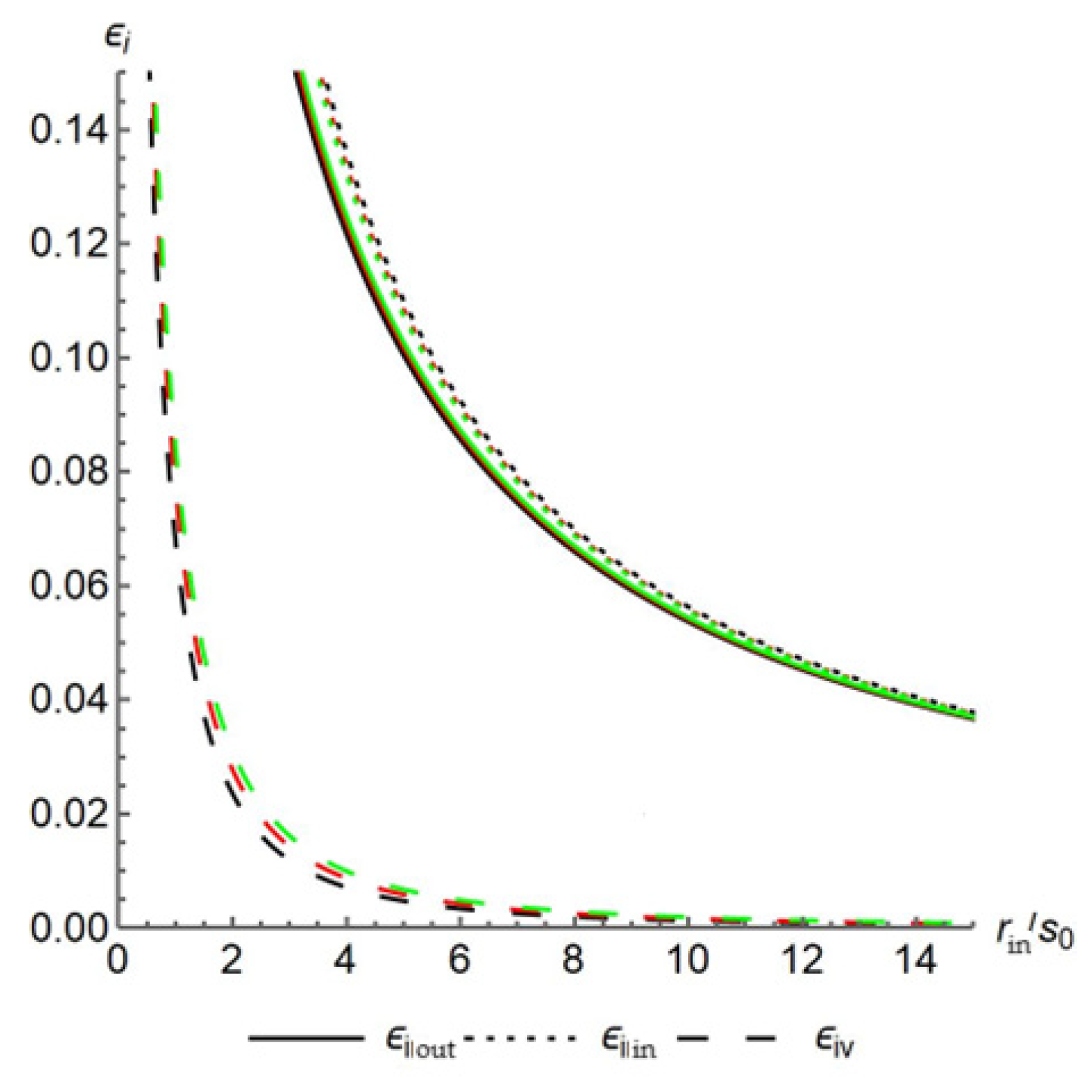
To establish the regularities of the circular bending process and the effects of strain hardening and the plastic anisotropy of the sheet material, let us examine the influence of these factors separately.
In the first case, the calculations assumed that an isotropic billet was being bent , with a hardening exponent n of 0 (the material does not harden), 0.15, and 0.30. It was assumed in the calculations that since, for most materials, the elastic strain , at which the yield strength is reached, is small.
It was found that the hardening has almost no effect on either the nature or the magnitude of strain intensity. As
n increases, a slight increase in strain intensity is observed (
Figure 10).
Figure 11 presents the results of calculations of the geometric parameters of the bending process. From
Figure 11a, it can be seen that an increase in the hardening exponent leads to a shift in the neutral surface radii (based on the stress and total strain) toward the inner (concave) surface, resulting in a more intense reduction in billet thickness (
Figure 11b). Thus, as
n increases, the thickness of the billet decreases more significantly than without hardening, but the thinning can still be neglected when
.
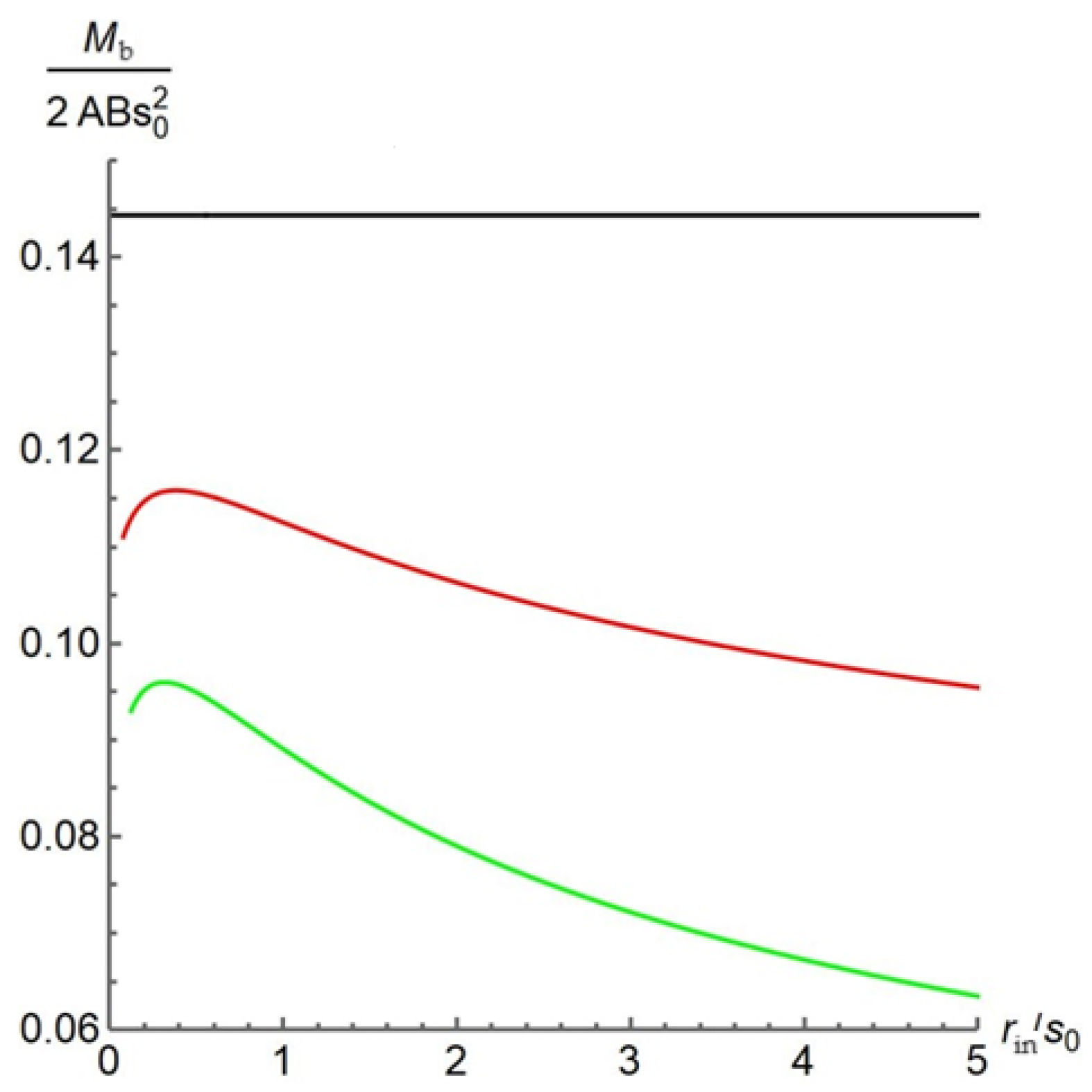
The moment required for plastic bending without hardening remains unchanged during the deformation that increases curvature (
Figure 12). The moment calculated using the developed mathematical model matches the moment calculated using the known formula without considering hardening [
1]. Clearly, hardening should lead to a significant increase in the bending moment. However, as shown in
Figure 12, an increase in the hardening exponent results in a decrease in the bending moment. This can be explained by the fact that the hardening coefficient
A, which is not considered in this case, is also a function of the hardening exponent and increases non-linearly with it.
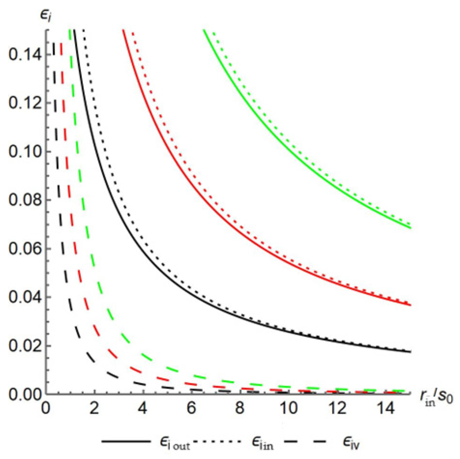
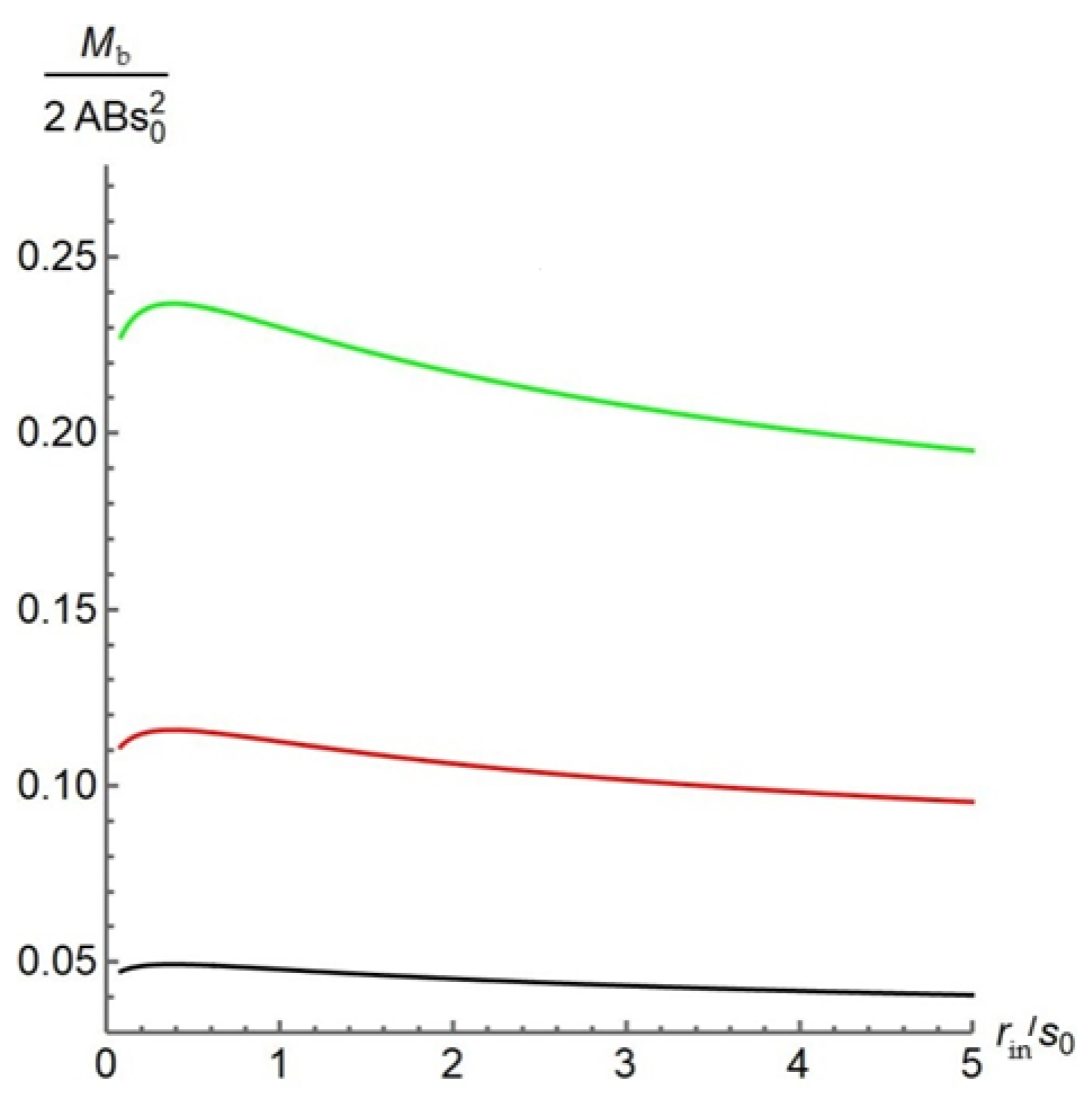
In the second case, the calculations assumed that the billet being bent had a modified Lode coefficient of 0.55, 1.15 (isotropic material), and 2.15. It was also assumed that
It was determined that the strain intensity and the bending moment increase with the Lode coefficient based on the calculations presented (
Figure 13 and
Figure 14). The character of the distribution of these parameters remains unchanged.
Additionally, it was established that the value of the Lode coefficient, and thus the plastic anisotropy, does not affect the geometric parameters of the bending process, such as the position of the neutral surfaces based on the stress and total strain, as well as the thinning of the billet.


