Abstract
Solar trackers represent a significant advancement in enhancing the efficiency of solar energy collection. This study describes the development and implementation of a passive solar tracker featuring a single horizontal axis of rotation and an innovative guide slot mechanism. The tracker is designed to be used with solar radiation-capturing devices. The guide slot mechanism is specifically engineered for a designated date, location, and period to follow the solar trajectory accurately. A contact follower moves along the guide slot, which drives a tracker disk to rotate by the solar trajectory. The mechanism is activated by the movement of a liquid container attached to a spring, thereby storing potential energy. The container releases the liquid through a mechanical valve that regulates the container’s movement, while the guide slot mechanism converts this movement into controlled rotational motion, which is transferred to a mobile structure mounting the solar panel. Notably, the majority of materials utilized in this construction are recycled. Furthermore, the solar tracker proposed in this work is designed to be operable by individuals with limited prior knowledge on the topic, emphasizing the primary contribution of this study: its potential to revolutionize energy collection in developing countries and marginalized urban areas. No similar systems are found upon comparison with existing models in the literature. Experiments conducted with a static solar panel and the same panel integrated into the passive solar tracker revealed a 30.87% improvement in energy collection efficiency over static solar panels.
1. Introduction
The increasing demand for energy is leading to higher carbon emissions, which in turn accelerates concerns related to climate change. To address this issue, the deployment of renewable energy (RE) is on the rise, facilitating a global transition to sustainable energy sources []. As a clean energy option with minimal adverse environmental effects, regenerative energy presents a viable alternative to reduce dependence on fossil fuels [,]. Continuous innovation in industrial science is evolving to meet the urgent need for practical solutions within the energy and mechanical engineering sectors. Recent advancements in technology, mechanics, and materials have significantly enhanced sustainable energy production. Among these renewable sources, solar energy plays a crucial role, and scientific research is focused on increasing its efficiency and output [,]. Solar energy is one of the most abundant and essential renewable sources today due to its declining costs and increased accessibility [,]. It can be harnessed almost anywhere [,,]. Solar cells are the primary source used to convert solar energy into electricity [,]. Most people rely on solar cells, a widely adopted technology integrated into compact devices, to generate photovoltaic (PV) energy. Solar cells convert solar radiation into electricity as expected [,,]. To achieve optimal efficiency in this conversion, sunlight must hit the surface of the solar panel at a 90° angle []. Photovoltaic systems are now extensively used worldwide, connected to the power transmission grid and functioning as photovoltaic installations []. Photovoltaic technology is one of the most promising options for the future due to its simplicity, scalability, and lower costs associated with manufacturing, operation, and maintenance [].
In recent years, solar PV, wind, and geothermal energy development has advanced significantly []. However, the amount of power generated by photovoltaic systems depends on several factors, including their efficiency, sunlight reaching the modules, and the technology employed []. Conventional PV panels need to be more robust in terms of efficiency. They typically generate only 12–18% of electricity and 82–88% of heat from solar radiation []. Therefore, improving conversion efficiency by reducing the operating temperature of PV systems is critical. Ongoing research aims to enhance energy production, address the challenges the photovoltaic sector faces, and achieve better results. The use of solar power systems has advantages and disadvantages, as outlined in Table 1 []:

Table 1.
Advantages and disadvantages of employing PV systems.
Research and development efforts are focused on maximizing energy collection in photovoltaic systems by studying and developing new technologies, as the power generated by these systems is directly influenced by the amount of solar radiation received [,]. The literature reports various techniques for increasing the efficiency of photovoltaic energy systems [,]. The main methods for improving power generation include cooling, cleaning, solar trackers, floating PV systems, and maximum power point tracking (MPPT) controllers [].
One notable technique to optimize the efficiency of solar photovoltaic systems is the solar tracker [,,,,]. A solar tracker is a mechanical device that adjusts the angle of solar panels to maximize sunlight absorption [,,,,,]. This alignment allows PV panels to maintain a right angle to the solar rays, enhancing energy production. The peak energy output occurs at a specific position called the maximum power position (MPP), which can change constantly based on variations in solar radiation and temperature. Monitoring MPPs is essential to maintain a consistently high level of energy generation [,,]. Figure 1 shows the classification of solar tracker systems [,].
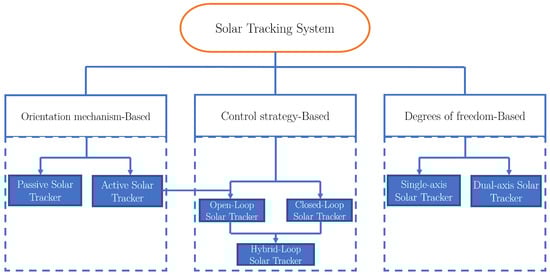
Figure 1.
Solar tracker system classification.
According to Figure 1 and based on their orientation mechanism, solar trackers can be divided into active and passive systems [,,,]. Passive tracking systems use stationary solar panels with minimal susceptibility to wind forces. These panels are positioned by exposing the solar cells to sunlight and aligning them towards the sun when its rays are most intense []. The cost-effective nature of this system can lead to an increase in collection efficiency of up to 23% [,]. Active tracking systems employ rotary or linear actuators, making their implementation more complex and costly [].
Depending on the rotational movement of the axis, single-axis or dual-axis active tracking systems are available []. By tracking the path of the Sun along a single axis, such as horizontal, vertical, polar, or inclined [,,], single-axis systems have the potential to improve their collection efficiency by 12–25% [,]. The efficiency of these trackers depends on factors such as climate, location, season, and system design [,,]. Active dual-axis solar trackers have been reported to enhance collection efficiency by 17.1–31.1% [,]. Sun tracking systems with two axes generally revolve around either azimuthal and elevation axes or the polar and solar declination axes [,,,]. To achieve this design, pedestals or central support structures incorporating linear actuators for polar tracking and a slew motor for azimuthal monitoring can mount ring-rail-type structures designed to support extensive PV systems subject to high gusts. Dual-axis solar trackers are more effective than single-axis solar trackers because they can capture light from both the horizontal and vertical planes despite the higher production cost [,,]. Studies [] have confirmed the benefits of using solar trackers. Findings suggest that using a tracker to move a solar panel around might significantly improve its power output.
In recent work, talking about passive solar trackers [], an innovative concept for a solar tracker was presented that would maximize the collection of solar energy by using intelligent materials. This technique features a passive solar tracker that employs a shape-memory alloy thermomechanical actuator to modify the inclination angle of the solar panels, allowing them to follow the Sun effectively.
In addition, in [], a mechanical solar concentrating system was also introduced. This system includes a single-axis tracking mechanism that requires no energy, electronics, or specialized materials. It harnesses nocturnal wind energy to propel itself. A functional three-dimensional model with low-cost components was designed, constructed, and evaluated. In [], a passive solar tracker based on bimetallic band deflectors was developed to operate independently of night temperatures. Field trials were conducted with both the proposed tracker and a fixed system. Energy harvesting, power density, and output were performance metrics. The suggested tracker produced 1081.7 Wh daily, compared to 716.7 Wh from a stationary system. The energy harvesting system suggested was 24.86% more effective than the fixed system.
In other examples, active solar trackers, such as single-axis solar tracker prototypes, have been proposed. For example, in [], a solar tracking system with a single axis was developed and deployed using an Arduino Uno microcontroller to optimize daily energy production. This work proposed an automated system that tracks the Sun using a single axis and operates in a closed-loop configuration. A similar methodology was presented in [,]. Their Sun tracking system employed a mechanical frame, linear actuator, microprocessor, and azimuth positioning sensors. They obtained an efficiency of around 30.3% and 57.4%, respectively. Similarly, ref. [] presented a fully autonomous single-axis closed-loop Sun tracking system using Arduino as a control device. They achieved 10–23% efficiency in the proposed system. Another example that did not use Arduino was proposed in [], which implemented a system that drives a DC motor in response to inputs from light sensors, allowing the PV panel to move in sync with the system.
Following the aforementioned methodologies, in [], a method was presented for sizing and designing a single-axis solar tracker using MATLAB R2020b as software simulation and Arduino for control actions.
Another type of solar tracker is the dual-axis tracker. For instance, using a closed-loop method [], a dual-axes solar tracker based on Arduino and servomotors was proposed. The system was developed, built, and tested under various conditions to assess its efficiency, which was found to be 45%. In [], a low-cost two-axis solar tracker was described, where researchers created a linear system to model the dynamics of a sun tracker using real-time data. This linear model was incorporated into the sun-tracking algorithms, leading to a reported 32% improvement in energy efficiency. For sensorless solar trackers, [] suggested a low-cost solar tracking device to optimize PV panel solar energy collection in tropical regions. This design featured a mechanically operated ball-joint mechanism to achieve the objectives. The study focused on meticulously designing, manufacturing, and assembling three essential components: the tracking mechanism, collapsible solar panels, and the circuitry. The primary tracking mechanism involved a ball–joint system with four actuation motors, ensuring efficient operation. This solar tracking device outperformed conventional static panels by 37%. More recent methodologies, such as that in [], introduced a genetic method to enable a solar tracker robot to evolve and accurately follow the movement of the Sun. The robotic system was constructed using an Arduino microcontroller and servomotors, demonstrating its ability to track the Sun’s position effectively. Additionally, in [], an autonomous solar tracking system that operates without sensors was presented. The system can monitor the movement of the Sun in horizontal and vertical axes. A unique solar tracking approach was developed using a robust sampling-based particle filter (PF) algorithm.
In another innovative robotic approach, [] introduced a solar tracking technique using a collapsible solar gathering system designed for an amphibious robot. This system featured four servomotors that sequentially retracted four foldable small solar panels, allowing the robot to adjust the panel orientation for maximum power efficiency based on its location and time. This solar tracker proved effective, increasing solar energy collection efficiency by 62.4%. Furthermore, electronic monitoring systems for MPPT, along with solar tracking, have been integrated into dual-axis solar trackers to improve their accuracy and performance, as noted in [].
Recent state-of-the-art reviews, such as those in [,], indicate that various methods have employed different control mechanisms, including sensor-based tracking algorithms and methodologies, astronomical equations, fuzzy logic [], neural networks, time-based tracking systems, solar position calculation algorithms [], Internet of Things methods (IoT) [,,], and Petri networks [].
This study makes several contributions related to solar tracking:
- The first contribution is the introduction of a new mechanism for passive solar trackers called the guide slot mechanism. This innovative design uses potential energy to imitate the solar trajectory, improving the ability of solar panels to track the Sun. A key feature of this mechanism is the guide slot, which regulates the rotation angle of the panel, enhancing its solar trajectory tracking accuracy.
- The second contribution highlights the efficiency observed in tests conducted. This study demonstrates an increase in solar radiation collection with the proposed solar tracker design compared to a static solar panel positioned parallel to the ground. The efficiency achieved with the new solar tracker design surpasses results from previous works on both passive and active solar trackers, as illustrated in Figure 17.
- The third contribution emphasizes the practicality and accessibility of this work. The solar tracker can be built and operated by individuals without technical expertise in solar tracking. Most materials used in the design are recycled, which showcases its versatility and cost-effectiveness. This makes the design particularly suitable for use in developing countries, marginalized urban areas, and urban settings. Additionally, it can be integrated into high school curricula, enabling students to participate in the fight against climate change.
- The fourth contribution provides a method for creating the primary component of the solar tracker with the guide slot mechanism. It outlines the main variables needed to create the guide slot’s trajectory and explains how to construct it using wood and simple tools. The disk with the guide slot is a key component. Ultimately, this work aims to present a functional solar tracker design that can be applied in various contexts to address environmental challenges, including thermal applications.
The organization of this paper is as follows. Section 2 outlines the methodology proposed for the single-axis solar tracker, along with details on the design and components. It also discusses the operational mechanism of the prototype. Section 3 presents the findings and limitations of the study. Finally, the conclusions of this study are summarized in Section 4.
2. Materials and Methods
This section outlines the components of the solar tracker test bench equipped with a guide slot and explains the function of each element. It also details the design of the guide slot for a specific location and date. Additionally, this section presents an example of a problem encountered when designing a guide slot and compares the trajectories of the guide slots needed to follow the solar path in June and December, specifically on the 15th day, at the same location. Finally, it discusses the design of a guide slot suitable for application in other regions.
2.1. The Proposed Solar Tracking System
The test bench utilized for this experimentation features a 3D prototype with components, as illustrated in Figure 2. Most of the materials used in this work are recycled, and their characteristics were chosen based on experimental evaluations. The prototype consists of a vertical support (1) that holds a piece of wood (2) securely at a specific height. Attached to one end of this piece of wood (2) is a spring (3), while the other end connects to a container (4) intended for storing liquid. When the container fills with water, the spring (3) is stretched, storing potential energy until the fluid is released from the container (4). Container (4) is fitted with a hose (6) and a valve (7) that permits controlled discharge of water. At the base of the container (5), a mechanical link (8) connects the vertical movement of the container (4) to a mechanism that converts this vertical motion into rotational movement, which is governed by the guide slot (10a) on the guide slot plate (10). The support (11) secures the guide slot plate (10) to a wooden base (14) with the aid of an angle support (13) and an inclined support (12). A follower disk (15) is linked to the shaft (17) through a mechanical connector (16). The guide slot plate (10) and the follower disk (15) are aligned centrally via a bushing, allowing for the free rotation of the follower disk (15). The shaft (17) is mounted on vertical supports (18) and (31), which are anchored to the wooden base (14) using angular supports (32) and (19). A structure for mounting the solar panel (30) attaches to the shaft (17) and comprises both aluminum parts (21, 24, 25, 28) and plastic components (22, 23, 26, 27). Consequently, as the follower disk (15) rotates, the solar panel (30) rotates in unison.
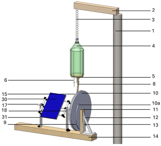
Figure 2.
Three-dimensional design with enumerated elements of solar tracker test bench with guide slot, each number represents a part in the solar tracker design and a number with a letter represents a significant feature of a part.
When container (4) is filled with liquid, spring (3) stretches, and container (4) moves downward. The solar tracker is initiated by manually opening valve (7) at a predetermined time, allowing a specific flow rate, which generates the process water discharge from the container over a period of time as shown in Figure 4a. A specific volume of liquid is discharged from a container (4), generating an upward vertical movement. This upward motion is transmitted through the link (8) to the follower disk (15) via a contact follower (9) attached to the link (8). The contact follower (9) tracks the trajectory of the guide slot (10a), generating rotational movement of the follower disk (15) as it is pushed by the contact follower (9) traversing the slot (15a). Thus, the rotational motion of the follower disk (15) is conveyed to the solar panel (30), enabling it to track the Sun’s path on the specified date for which the guide slot (10a) was designed. As illustrated in Figure 3, the tracking disk is shown transparently to clarify the mechanical connection among the contact follower (9), slot (15a), and guide slot (10a).
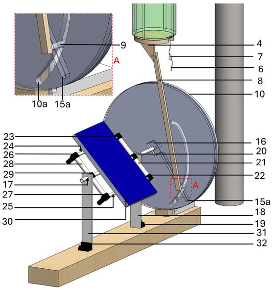
Figure 3.
Three-dimensional design with enumerated elements of solar tracker test bench with guide slot and transparent follower disk (15), each number represents a part in the solar tracker design and a number with a letter represents a significant feature of a part.
2.2. Guide Slot Design
In the design of the guide slot, the container’s vertical upward movement was first characterized. Experiment results are displayed in Figure 4a, which shows the initial discharge of water from the container at a rate of 48 mL over min. After 10 h, L of water remained out of a total of 9 L. The vertical upward movement of container M generated a trajectory of cm over the 10 h, as shown in Figure 4b.
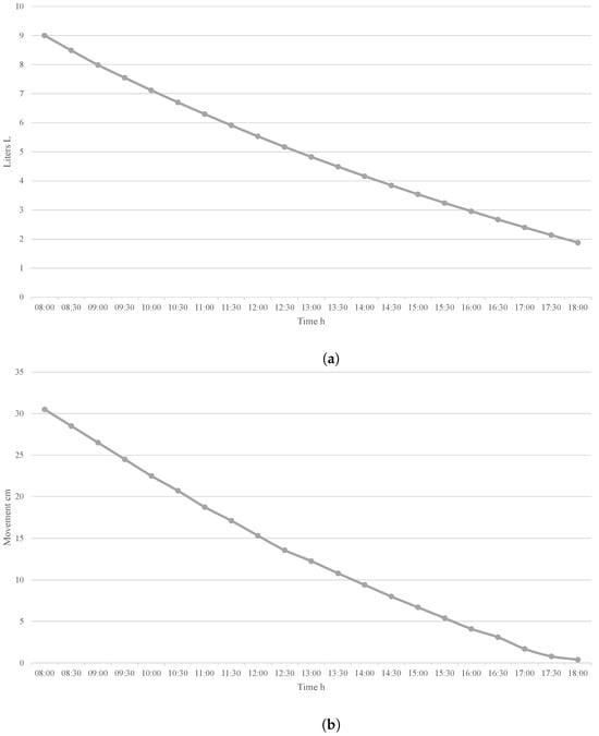
Figure 4.
Results of the characterization. (a) Discharge of water from the container. (b) Vertical upward movement of the container over a 10 h period.
For the guide slot design, specific data were utilized. The first variable is the characterization of the vertical upward movement of the container, as illustrated in Figure 4b, represented by ⋯ . In Figure 5, indicates the lowest point of the container when filled with a specified amount of water and serves as the starting point for solar tracking. The interval between and represents the vertically upward distance the container moved when discharging water through the manual valve over 1 h. represents the total distance the container moved during the proposed 10 h period tracking the solar trajectory, from 8:00 a.m. to 6:00 p.m., moving from east (E) to west (W). The second variable consists of the angles needed to follow the solar trajectory along a single horizontal axis on a given date, represented by ⋯ . Here, is the angle pointing directly at the Sun at 8:00 a.m. Each corresponds to the angle required to point towards the Sun at specific times and locations throughout the day.
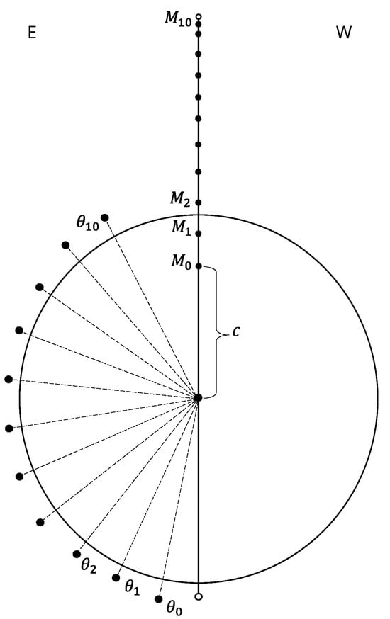
Figure 5.
Variables for guide slot construction.
The proposed variable C represents the distance between the container and the guide slot mechanism’s S-link relative to the follower disk’s rotation axis. The length of the S-link was determined, with one end connected to point and the other connected to , as shown in Figure 6a at point . Each M and corresponding were connected to form a shape represented in Figure 6b, and the points were joined with a curved line to create , the guide slot designed to follow the solar trajectory on a given date, as illustrated in Figure 6c. Consequently, the guide slot plate (10) is proportional to the movement of container M.
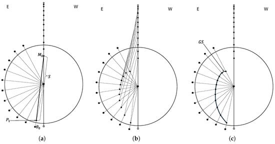
Figure 6.
Guide slot design sequence. (a) S-link of the guide slot mechanism. (b) Marking the junction points. (c) Joining the points with a curved line to form .
In the design depicted in Figure 6a, links S and C were set at 38 cm and 16.5 cm, respectively. These dimensions were selected to ensure a smooth curve , preventing the mechanism from locking and ensuring the contact follower does not get stuck while crossing the guide slot. Figure 7 displays different with S-link measurements of cm, 38 cm, and cm. Significant length variations of S could cause the previously mentioned locking issue. Therefore, it is crucial to determine an appropriate length for the S-link to design a guide slot trajectory with a smooth curve using the proposed method.
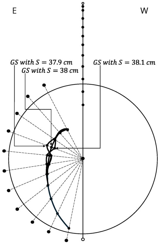
Figure 7.
Different with , , and .
It is important to note that the guide slot is designed for a specific date. While a guide slot can function over several days, its accuracy in solar tracking diminishes over time. This article aims to address that concern. Additionally, the distance of the S must be considered. As shown in Figure 8, there are two guide slots for June 2023 and December 2023. The size and shape of the guide slots are noticeably different. The most significant point is that the June link needs to be more suitable for the December guide slot, which requires a link of a different length.
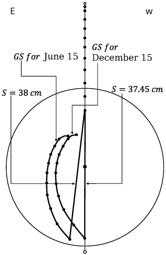
Figure 8.
Different for the months of June and December.
2.3. Application of the Design in Other Regions
The proposed solar tracker design is not limited to a specific region but is adaptable to various locations. The development of the guide slots for these regions is shown in Figure 9a,b for Winnipeg, Canada, and Santa Cruz, Argentina, respectively. The only variables modified from the proposed design were the angles required to follow the solar trajectory concerning the proposed locations and S, with a length of cm for Canada and cm for Argentina. Both designs were developed on 15 March 2023, from 8:00 a.m. to 7:45 p.m. for Canada and from 9:00 a.m. to 7:00 p.m. for Argentina.
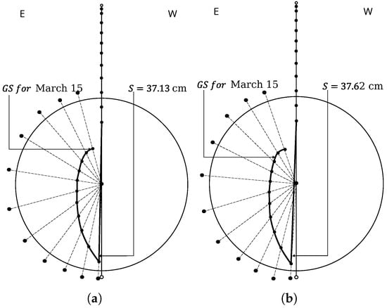
Figure 9.
Guide slot in other regions. (a) Guide slot for Canada. (b) Guide slot for Argentina.
2.4. Construction of the Guide Slot
The construction of the guide slot is a detailed process that involves several steps. A vertical line V is drawn to create the guide slot, and a reference point is taken to draw the angles that follow the solar trajectory at a specific location and date, as shown in Figure 10a. Secondly, the P points were marked as shown in Figure 10b. By knowing the distances of S and C, the length between and is determined. The third step is to make circles of the diameter of the contact following the points marked previously, as shown in Figure 10c.
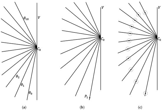
Figure 10.
Guide slot construction sequence. (a) Making the angles that follow the solar trajectory. (b) Marking the points P. (c) Making circles of the diameter of the probe.
In the fourth step, the circles are joined by outlining a circular piece of proposed diameter to generate a smooth curve. The fifth step is to glue the drawing of the guide slot on the wooden disk in a centered way, as shown in Figure 11a,b.
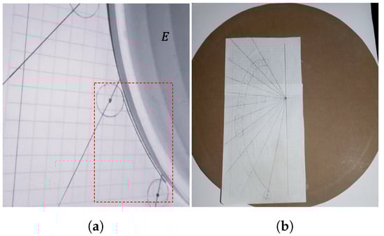
Figure 11.
(a) Joining the circles by means of a proposed circular piece. (b) Glueing the drawing of the guide groove to the wooden disk.
The sixth step consists of drilling holes large enough to allow the use of a woodcutter. The seventh step consists of filing the guide channel to the desired shape, as shown in Figure 12a,b.
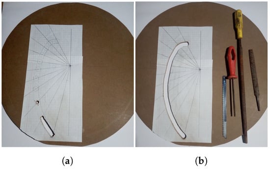
Figure 12.
(a) Drilling holes and cutting the wooden disk. (b) Filing the wood to form the guide slot.
3. Results and Discussion
Tests for radiation collection by a panel mounted on a solar tracker with a guide slot mechanism compared to a static panel were carried out on 14 June 2023 and 15 June 2023 from 8:00 a.m. to 6:00 p.m. at Cadereyta de Montes, Querétaro, Mexico. This location was chosen due to its high altitude of 2024 m above sea level and an atmospheric pressure of 1015 hPa, which provides a unique atmospheric condition for solar energy collection. The area is a semi-desert with a high temperature and arid environment and experiences moderate and heavy rainfall, making it an ideal test site for solar technology. In the location in the months of June, July, and May, less azimuthal movement of the solar panel is required to follow the trajectory of the sun, so the tests were performed in June, allowing the static panel to be placed parallel to the ground, which allows a comparison with the panel mounted on the solar tracker since it cannot perform the azimuthal movement. A similar test was also carried out on 12 November 2024; on this date, a wide azimuthal movement is required to be compared to the one required in June. The requirement of a higher azimuthal movement disfavors the solar radiation capture capacity of both panels, but the one which is more affected is the static solar panel. The project included a solar tracker of a single horizontal axis of rotation with a slot guide mechanism. A solar panel of 32 cm × cm and 10 W (ECO-WORTHY PV-HS8303) was mounted, and a static solar panel of the same characteristics was positioned parallel to the ground (because of the location and date; the parallel position is a good choice for static panels). A spring of 32 cm was used at rest, as well as a container of 9 L, a guide slot mechanism, a mobile structure, a structure, a hose, and a manual valve, as shown in Figure 13a–c, and the panel rotated from east (E) to west (W).
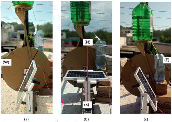
Figure 13.
Single-axis solar tracker system proposed in this work completed a rotation of 152° from east (E) to west (W) over a 10 h period. (a) Evening position. (b) Noon position. (c) Morning position.
In order to ensure the correct execution of the system, the operator must perform two tasks:
- The first is to activate the valve at the indicated time.
- The second is to fill the container with the required amount of water. Marks should be placed on the container to verify the water required.
When the container was filled with 9 L of water (this process required no more than 10 min to complete), potential energy was stored in the spring, and the spring was stretched to cm, giving a total length of cm. The container descended vertically cm, and the spring was stretched. The mobile structure was mechanically connected to the guide slot mechanism through the follower disk of the guide slot mechanism, which was pivotally connected to the lower part of the container. The mobile structure was used to mount the solar panel, while the container was employed to install the pipe and manual valve. We waited until 8:00 a.m. to activate the valve, considering an initial water discharge from the container of 48 mL in min.
With the discharge flow mentioned, the container had a controlled vertical upward movement of cm over 10 h. The panel completed a rotation of 152° from east (E) to west (W) and through Equation (1) [], where the energy generated by a panel mounted on a solar tracker with a guide slot mechanism represented with and the energy generated by a static panel represented with , the results of the tests on 14 June 2023 and 15 June 2023 were % and % more energy captured by the solar panel mounted to the solar tracker of the single horizontal axis of rotation with guide slot mechanism. The results of the test on 12 November 2024 show an efficiency of 41.7% higher for the panel mounted to the solar tracker, but as previously mentioned, this is because in November a higher azimuthal movement is required to follow the solar trajectory than in June. Furthermore, in the test conducted in June, the conditions are more favorable for comparing the efficiency of the panel mounted to the tracker and the static panel parallel to the ground since less azimuthal movement is required. The prototype is shown in Figure 11a. Compared to the static solar panel horizontal to the ground, Table 2, Table 3 and Table 4 show the test data, and Figure 14, Figure 15 and Figure 16 represent the collected data, further emphasizing the impact of this research. Additionally, the container was filled manually. The filling process must be conducted daily, and a manually activated valve was used to initiate the control of the fluid discharge from the container. A test was conducted using 9 L of water at the solar tracker location over 72 h to quantify water loss due to evaporation. After this period, the remaining water was measured with an electronic scale, yielding a result of 8.963 L. It was concluded that short-term evaporation does not significantly impact efficiency. Furthermore, a resistance test of the structure revealed that it can support 3.98 kg. However, it has already exhibited difficulty rotating the mobile structure. The increased weight necessitates greater effort from the spring to operate the mechanism. The panel utilized weighs 0.739 kg, thus allowing for the installation of at least five panels of the same dimensions in the proposed design. However, this would require modifications to the spring and increased water volume within the container to accommodate the augmented moving mass.
Table 2.
Test power in W with data of a solar panel placed on a single-axis solar tracker using stored potential energy compared to a static solar panel. The experiments were conducted on 14 June 2023, from 8:00 a.m. to 6:00 p.m.
Table 3.
Test power in W with data of a solar panel mounted on a single-axis solar tracker using stored potential energy compared to a stationary solar panel. The experiments were conducted on 15 June 2023, from 8:00 a.m. to 6:00 p.m.
Table 4.
Test power in W with data of a solar panel placed on a single-axis solar tracker using stored potential energy compared to a static solar panel. The experiments were conducted on 12 November 2024, from 8:00 a.m. to 5:00 p.m. The solar trajectory could not be followed until 6:00 p.m. because of the mountains near the experimental area.
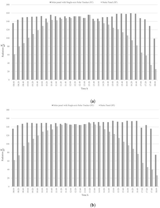
Figure 14.
Solar radiation of the solar panel with a single-axis solar tracker and static panel during the period from 8:00 a.m. to 6:00 p.m. (a) On 14 June 2023. (b) On 15 June 2023.
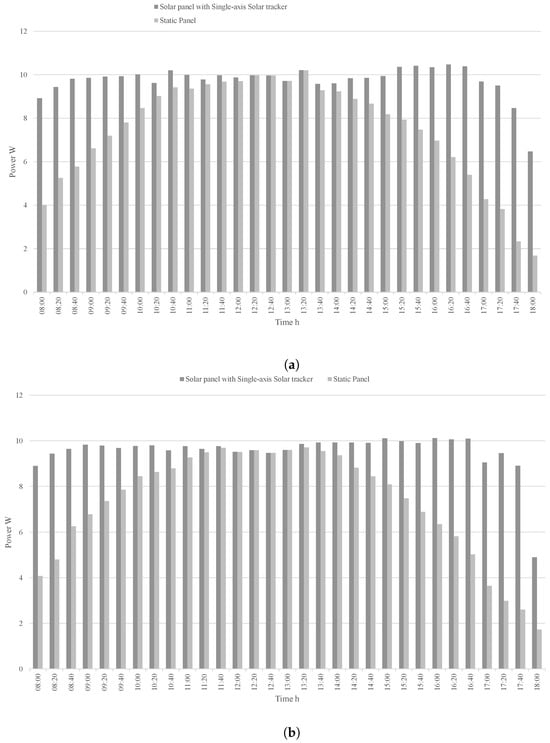
Figure 15.
Power area graph of the solar panel with a single-axis solar tracker and static panel during the period from 8:00 a.m. to 6:00 p.m. (a) On 14 June 2023. (b) On 15 June 2023.
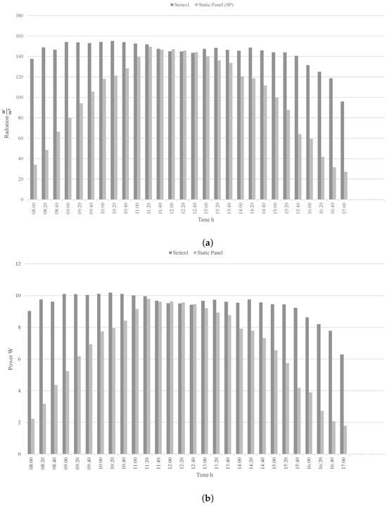
Figure 16.
(a) Solar radiation and (b) power area graph of the solar panel with a single-axis solar tracker and static panel during the period from 8:00 a.m. to 5:00 p.m. on 12 November 2024.
3.1. Comparison to Contemporary Related Work
Table 5 displays a comparative analysis between this research and previously published studies. The efficiency achieved in this study is comparable to prior efforts using microcontrollers and surpasses similar work with one-axis passive solar trackers. While previous studies using microcontroller methods have achieved better efficiency, it is essential to note that the production costs in those studies are significantly higher than those of the passive single-axis (horizontal) guide slot solar tracker.
Table 5.
Comparison with related work.
Additionally, as shown in Figure 17, the passive solar tracker design based on a defined guide slot path performs better than some active types of trackers utilizing microcontrollers and outperforms other passive solar tracker designs.
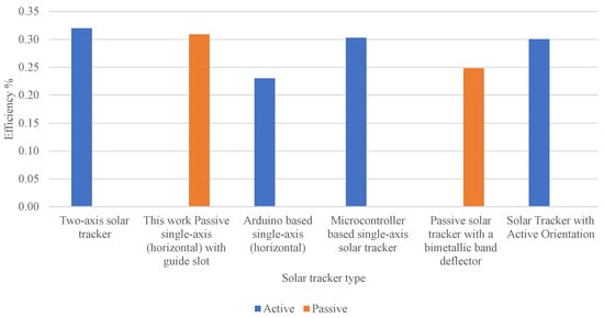
Figure 17.
Comparison of the efficiency of active and passive solar trackers.
3.2. Limitations of the Study
One limitation of this study is the requirement for an appropriate climate, as energy production depends heavily on a predominantly sunny environment. Using a guide slot for this prototype is another limitation, as different guide slots would need to be manufactured depending on the geographical area. However, the design is scalable. Furthermore, this solar tracker can be adapted for other applications, such as thermal energy storage or dual-axis tracking systems, although changes in materials would be necessary based on operating conditions. For instance, a robust structure is essential in environments with strong winds, and durable materials such as metals or polymers must be used to prevent deterioration over time.
4. Conclusions
This paper introduces a passive solar tracking technology featuring a guide slot mechanism. The newly designed solar tracker harnesses stored potential energy to propel the guide slot mechanism, enabling the solar panel’s movement and thereby improving solar energy harvesting efficiency. The solar tracker allows the solar cells to follow the sun’s trajectory by adjusting the tilt angle. This device can encourage the use of solar energy, especially in developing countries, because of its low construction cost, use of everyday materials, ease of operation, and compatibility for use by non-technical individuals. The previous sections presented a model comprised of several components where the only purchased material for constructing the solar tracker test bench with a guide slot mechanism was wood, used to build the follower disk and the disk with the guide slot; all other materials were recycled from previous applications. In this design, solar tracking was achieved using energy manually stored in a spring.
Additionally, the mechanical valve limiting the movement of the container was manually operated, and the guide slot disk was manually adjustable. The solar tracker demonstrated significantly enhanced solar radiation collection compared to other trackers reported in the literature. Another notable aspect is its versatility, which is applicable in urban and rural settings.
Below is a summary of the contributions of this work.
- A new mechanism for passive solar trackers improves the ability to follow the solar trajectory.
- The efficiency achieved with the proposed solar tracker design surpasses previous works on passive and active solar trackers, as shown in Figure 17.
- The design is particularly well-suited for implementation in developing countries and marginalized urban areas, but it is also feasible for urban settings and could be taught to high school students.
- The method for creating the main component of the solar tracker with a guide slot mechanism is clearly illustrated, highlighting the critical variables involved in generating the guide slot trajectory.
The findings revealed a consistent upward vertical displacement of 30.5 cm over 10 h. During this period, the solar panel completed a rotation of 152° from east to west. In two separate tests, the solar panel mounted on the 1-axis solar tracker with a guide slot mechanism captured 30.87% and 30.17% more energy output than the stationary solar panel placed horizontally on the ground.
Author Contributions
Methodology, J.L.P.-G. and M.A.G.-G.; validation, J.R.-R.; investigation, C.G.-V. and G.I.P.-S.; resources, R.V.C.-S. All authors have read and agreed to the published version of the manuscript.
Funding
This research received no external funding.
Institutional Review Board Statement
Not applicable.
Informed Consent Statement
Not applicable.
Data Availability Statement
The original contributions presented in the study are included in the article, further inquiries can be directed to the corresponding author/s.
Acknowledgments
I would like to thank my family for supporting me throughout my professional career and allowing me to test the solar tracker at their home. I would like to take this opportunity to mention that the project is currently under application for intellectual property protection at the Mexican Institute of Industrial Property (IMPI) under application number MX-002394.
Conflicts of Interest
The authors declare no conflicts of interest.
References
- Pirayawaraporn, A.; Sappaniran, S.; Nooraksa, S.; Prommai, C.; Chindakham, N.; Jamroen, C. Innovative sensorless dual-axis solar tracking system using particle filter. Appl. Energy 2023, 338, 120946. [Google Scholar] [CrossRef]
- Dehshiri, S.S.H.; Firoozabadi, B. Comparison, evaluation and prioritization of solar photovoltaic tracking systems using multi criteria decision making methods. Sustain. Energy Technol. Assess. 2023, 55, 102989. [Google Scholar]
- El Hammoumi, A.; Chtita, S.; Motahhir, S.; El Ghzizal, A. Solar PV energy: From material to use, and the most commonly used techniques to maximize the power output of PV systems: A focus on solar trackers and floating solar panels. Energy Rep. 2022, 8, 11992–12010. [Google Scholar] [CrossRef]
- Poojitha, K.; Ashwini, L.; Anjali, B.; Ramprabhakar, J. Solar tracker using maximum power point tracking algorithm. In Proceedings of the 2019 International Conference on Intelligent Computing and Control Systems (ICCS), Madurai, India, 15–17 May 2019; pp. 1528–1531. [Google Scholar]
- Klimek, K.; Kapłan, M.; Halchak, V.; Korobka, S.; Syrotyuk, S.; Konieczny, R.; Filipczak, G.; Dybek, B.; Wałowski, G. Orientation and Exposure Efficiency of a Solar Tracking Surface in Clear Sky. Appl. Sci. 2022, 12, 9118. [Google Scholar] [CrossRef]
- Alexandru, C. Optimization of the bi-axial tracking system for a photovoltaic platform. Energies 2021, 14, 535. [Google Scholar] [CrossRef]
- Ramful, R.; Sowaruth, N. Low-cost solar tracker to maximize the capture of solar energy in tropical countries. Energy Rep. 2022, 8, 295–302. [Google Scholar] [CrossRef]
- Sritoklin, A.; Malee, W.; Prugsanantanatorn, A.; Sapaklom, T.; Ayudhya, P.N.N.; Mujjalinvimut, E.; Kunthong, J. A Low Cost, Open-source IoT based 2-axis Active Solar Tracker for Smart Communities. In Proceedings of the 2018 International Conference and Utility Exhibition on Green Energy for Sustainable Development (ICUE), Phuket, Thailand, 24–26 October 2018; pp. 1–4. [Google Scholar]
- Ma, W.; Zhang, W.; Zhang, X.; Chen, W.; Tan, Q. Experimental investigations on the wind load interference effects of single-axis solar tracker arrays. Renew. Energy 2023, 202, 566–580. [Google Scholar] [CrossRef]
- Vargas, A.N.; Francisco, G.R.; Montezuma, M.A.; Sampaio, L.P.; Acho, L. Low-cost dual-axis solar tracker with photovoltaic energy processing for education. Sustain. Energy Technol. Assess. 2022, 53, 102542. [Google Scholar] [CrossRef]
- Mehdi, G.; Ali, N.; Hussain, S.; Zaidi, A.A.; Shah, A.H.; Azeem, M.M. Design and fabrication of automatic single axis solar tracker for solar panel. In Proceedings of the 2019 2nd International Conference on Computing, Mathematics and Engineering Technologies (iCoMET), Sukkur, Pakistan, 30–31 January 2019; pp. 1–4. [Google Scholar]
- Haris, O.; Darmawan, A.; Juliansyah, A. Efficiency Analysis of Using Solar Panel System Tracker to Static Solar Panel. In Proceedings of the 2021 IEEE 7th International Conference on Computing, Engineering and Design (ICCED), Sukabumi, Indonesia, 5–6 August 2021; pp. 1–6. [Google Scholar]
- Kumar, P.; Shrivastava, A. Maximum power tracking from solar PV system by using fuzzy-logic and incremental conductance techniques. Mater. Today Proc. 2022, 79, 267–277. [Google Scholar] [CrossRef]
- Engin, M. Controller Design for Parallel Mechanism Solar Tracker. Machines 2023, 11, 372. [Google Scholar] [CrossRef]
- Riad, A.; Zohra, M.B.; Alhamany, A.; Mansouri, M. Bio-sun tracker engineering self-driven by thermo-mechanical actuator for photovoltaic solar systems. Case Stud. Therm. Eng. 2020, 21, 100709. [Google Scholar] [CrossRef]
- Gómez-Uceda, F.J.; Moreno-Garcia, I.M.; Jiménez-Martínez, J.M.; López-Luque, R.; Fernández-Ahumada, L.M. Analysis of the influence of terrain orientation on the design of pv facilities with single-axis trackers. Appl. Sci. 2020, 10, 8531. [Google Scholar] [CrossRef]
- Al Garni, H.Z. The Impact of Soiling on PV Module Performance in Saudi Arabia. Energies 2022, 15, 8033. [Google Scholar] [CrossRef]
- Rezk, H.; Fathy, A. Stochastic Fractal Search Optimization Algorithm Based Global MPPT for Triple-Junction Photovoltaic Solar System. Energies 2020, 13, 4971. [Google Scholar] [CrossRef]
- da Rocha Queiroz, J.; da Silva Souza, A.; Gussoli, M.K.; de Oliveira, J.C.D.; Andrade, C.M.G. Construction and automation of a microcontrolled solar tracker. Processes 2020, 8, 1309. [Google Scholar] [CrossRef]
- Piotrowski, L.J.; Farret, F.A. Feasibility of solar tracking and fixed topologies considering the estimated degradation and performance of photovoltaic panels. Sol. Energy Mater. Sol. Cells 2022, 244, 111834. [Google Scholar] [CrossRef]
- Kumar, M.; Sharma, S.; Verma, N.; Jain, A.; Sharma, A.K. Design of a GPS Enabled Maximum Power Point Solar Tracker for Mobile Platform. In Proceedings of the 2021 6th International Conference on Communication and Electronics Systems (ICCES), Coimbatore, India, 8–10 July 2021; pp. 834–839. [Google Scholar]
- Ruelas, J.; Muñoz, F.; Lucero, B.; Palomares, J. PV tracking design methodology based on an orientation efficiency chart. Appl. Sci. 2019, 9, 894. [Google Scholar] [CrossRef]
- Ngo, X.C.; Nguyen, T.H.; Do, N.Y.; Nguyen, D.M.; Vo, D.V.N.; Lam, S.S.; Heo, D.; Shokouhimehr, M.; Nguyen, V.H.; Varma, R.S.; et al. Grid-connected photovoltaic systems with single-axis sun tracker: Case study for Central Vietnam. Energies 2020, 13, 1457. [Google Scholar] [CrossRef]
- Kuttybay, N.; Saymbetov, A.; Mekhilef, S.; Nurgaliyev, M.; Tukymbekov, D.; Dosymbetova, G.; Meiirkhanov, A.; Svanbayev, Y. Optimized single-axis schedule solar tracker in different weather conditions. Energies 2020, 13, 5226. [Google Scholar] [CrossRef]
- Gómez-Uceda, F.J.; Moreno-Garcia, I.M.; Perez-Castañeda, Á.; Fernández-Ahumada, L.M. Study of the dependence of solar radiation regarding design variables in photovoltaic solar installations with optimal dual-axis tracking. Appl. Sci. 2021, 11, 3917. [Google Scholar] [CrossRef]
- Hailu, A. Manual tracking for solar parabolic concentrator–For the case of solar injera baking, Ethiopia. Heliyon 2023, 9, e12884. [Google Scholar] [CrossRef]
- Baouche, F.Z.; Abderezzak, B.; Ladmi, A.; Arbaoui, K.; Suciu, G.; Mihaltan, T.C.; Raboaca, M.S.; Hudișteanu, S.V.; Țurcanu, F.E. Design and Simulation of a Solar Tracking System for PV. Appl. Sci. 2022, 12, 9682. [Google Scholar] [CrossRef]
- Katche, M.L.; Makokha, A.B.; Zachary, S.O.; Adaramola, M.S. A Comprehensive Review of Maximum Power Point Tracking (MPPT) Techniques Used in Solar PV Systems. Energies 2023, 16, 2206. [Google Scholar] [CrossRef]
- Musa, A.; Alozie, E.; Suleiman, S.A.; Ojo, J.A.; Imoize, A.L. A Review of Time-Based Solar Photovoltaic Tracking Systems. Information 2023, 14, 211. [Google Scholar] [CrossRef]
- Gutierrez, S.; Rodrigo, P.M.; Alvarez, J.; Acero, A.; Montoya, A. Development and testing of a single-axis photovoltaic sun tracker through the Internet of Things. Energies 2020, 13, 2547. [Google Scholar] [CrossRef]
- Petrusev, A.; Rulevskiy, V.; Sarsikeyev, Y.Z.; Lyapunov, D.Y. Solar tracker with active orientation. In Proceedings of the 2016 2nd International Conference on Industrial Engineering, Applications and Manufacturing (ICIEAM), Chelyabinsk, Russia, 19–20 May 2016; pp. 1–4. [Google Scholar]
- Sawant, A.; Bondre, D.; Joshi, A.; Tambavekar, P.; Deshmukh, A. Design and analysis of automated dual axis solar tracker based on light sensors. In Proceedings of the 2018 2nd International Conference on I-SMAC (IoT in Social, Mobile, Analytics and Cloud)(I-SMAC) I-SMAC (IoT in Social, Mobile, Analytics and Cloud)(I-SMAC), Palladam, India, 30–31 August 2018; pp. 454–459. [Google Scholar]
- Rani, P.; Singh, O.; Pandey, S. An analysis on Arduino based single axis solar tracker. In Proceedings of the 2018 5th IEEE Uttar Pradesh Section International Conference on Electrical, Electronics and Computer Engineering (UPCON), Gorakhpur, India, 2–4 November 2018; pp. 1–5. [Google Scholar]
- Melo, K.B.d.; Moreira, H.S.; Villalva, M.G. Influence of Solar Position Calculation Methods Applied to Horizontal Single-Axis Solar Trackers on Energy Generation. Energies 2020, 13, 3826. [Google Scholar] [CrossRef]
- Mubaarak, S.; Zhang, D.; Chen, Y.; Liu, J.; Wang, L.; Yuan, R.; Wu, J.; Zhang, Y.; Li, M. Techno-economic analysis of grid-connected pv and fuel cell hybrid system using different pv tracking techniques. Appl. Sci. 2020, 10, 8515. [Google Scholar] [CrossRef]
- Manjhi, S.K.; Rohan, R.; Kumar, D. Comparison of Static and Single Axis Solar Tracker. In Proceedings of the 2022 IEEE 2nd International Symposium on Sustainable Energy, Signal Processing and Cyber Security (iSSSC), Gunupur, Odisha, India, 15–17 December 2022; pp. 1–5. [Google Scholar]
- Elsayed, A.A.; Khalil, E.E.; Kassem, M.A.; Huzzayin, O.A. A novel mechanical solar tracking mechanism with single axis of tracking for developing countries. Renew. Energy 2021, 170, 1129–1142. [Google Scholar] [CrossRef]
- Alemayehu, M.; Admasu, B.T. Passive solar tracker using a bimetallic strip activator with an integrated night return mechanism. Heliyon 2023, 9, e18174. [Google Scholar] [CrossRef]
- Sahu, S.; Tiwari, S.; Patel, R. Analysis and Testing of Dual Axis Solar Tracker for a Standalone PV System. In Proceedings of the 2020 First International Conference on Power, Control and Computing Technologies (ICPC2T), Raipur, India, 3–5 January 2020; pp. 96–101. [Google Scholar]
- Szabo, R.; Ricman, R.S. A Genetic Algorithm-Controlled Solar Tracker Robot with Increased Precision Due to Evolution. Machines 2023, 11, 430. [Google Scholar] [CrossRef]
- Liu, C.; Sun, Z.; Huang, C.; Wang, S.; Xing, H.; Guo, S.; Liu, W.; Li, H. A Novel Solar Tracker with a Foldable Solar Harvesting Mechanism for an Amphibious Robot. In Proceedings of the 2022 IEEE International Conference on Mechatronics and Automation (ICMA), Guilin, China, 7–10 August 2022; pp. 1257–1262. [Google Scholar]
- Williams, K.; Qouneh, A. Internet of Things: Solar array tracker. In Proceedings of the 2017 IEEE 60th International Midwest Symposium on Circuits and Systems (MWSCAS), Boston, MA, USA, 6–9 August 2017; pp. 1057–1060. [Google Scholar]
Disclaimer/Publisher’s Note: The statements, opinions and data contained in all publications are solely those of the individual author(s) and contributor(s) and not of MDPI and/or the editor(s). MDPI and/or the editor(s) disclaim responsibility for any injury to people or property resulting from any ideas, methods, instructions or products referred to in the content. |
© 2024 by the authors. Licensee MDPI, Basel, Switzerland. This article is an open access article distributed under the terms and conditions of the Creative Commons Attribution (CC BY) license (https://creativecommons.org/licenses/by/4.0/).