
Design of a Maglev Stewart Platform for the Microgravity Vibration Isolation


Abstract
:1. Introduction
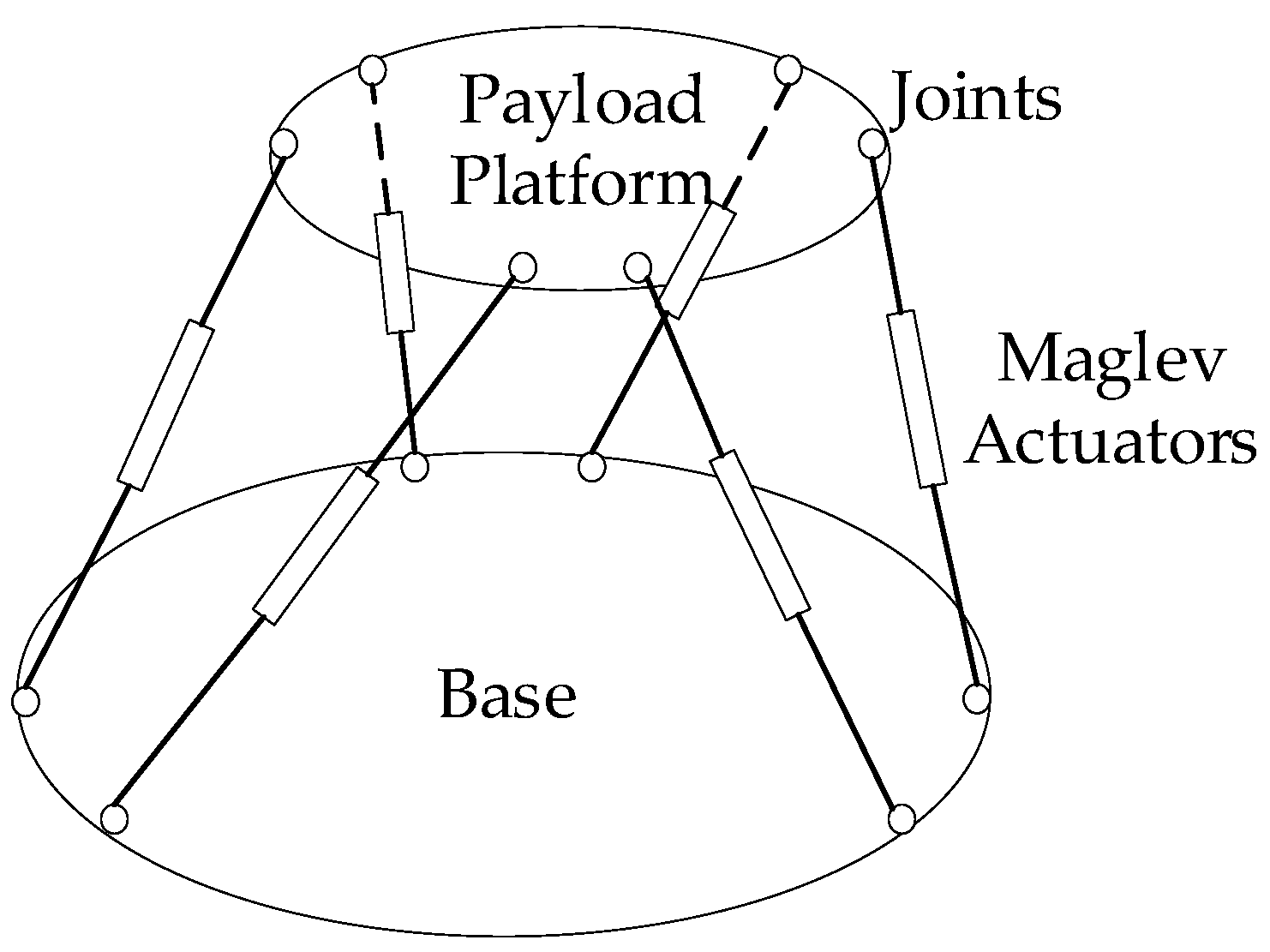
2. Configuration of Maglev Platform
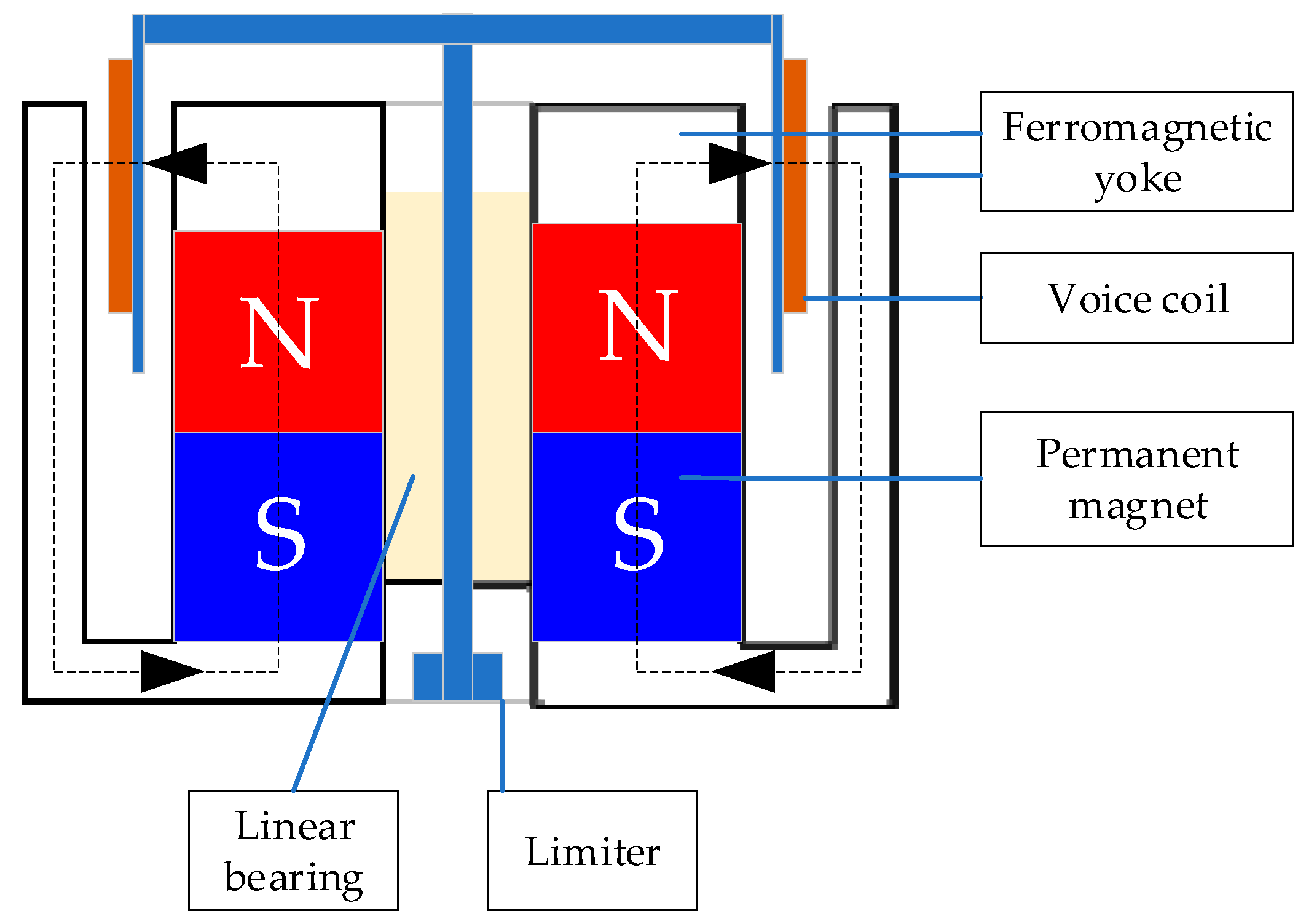
2.1. Actuator
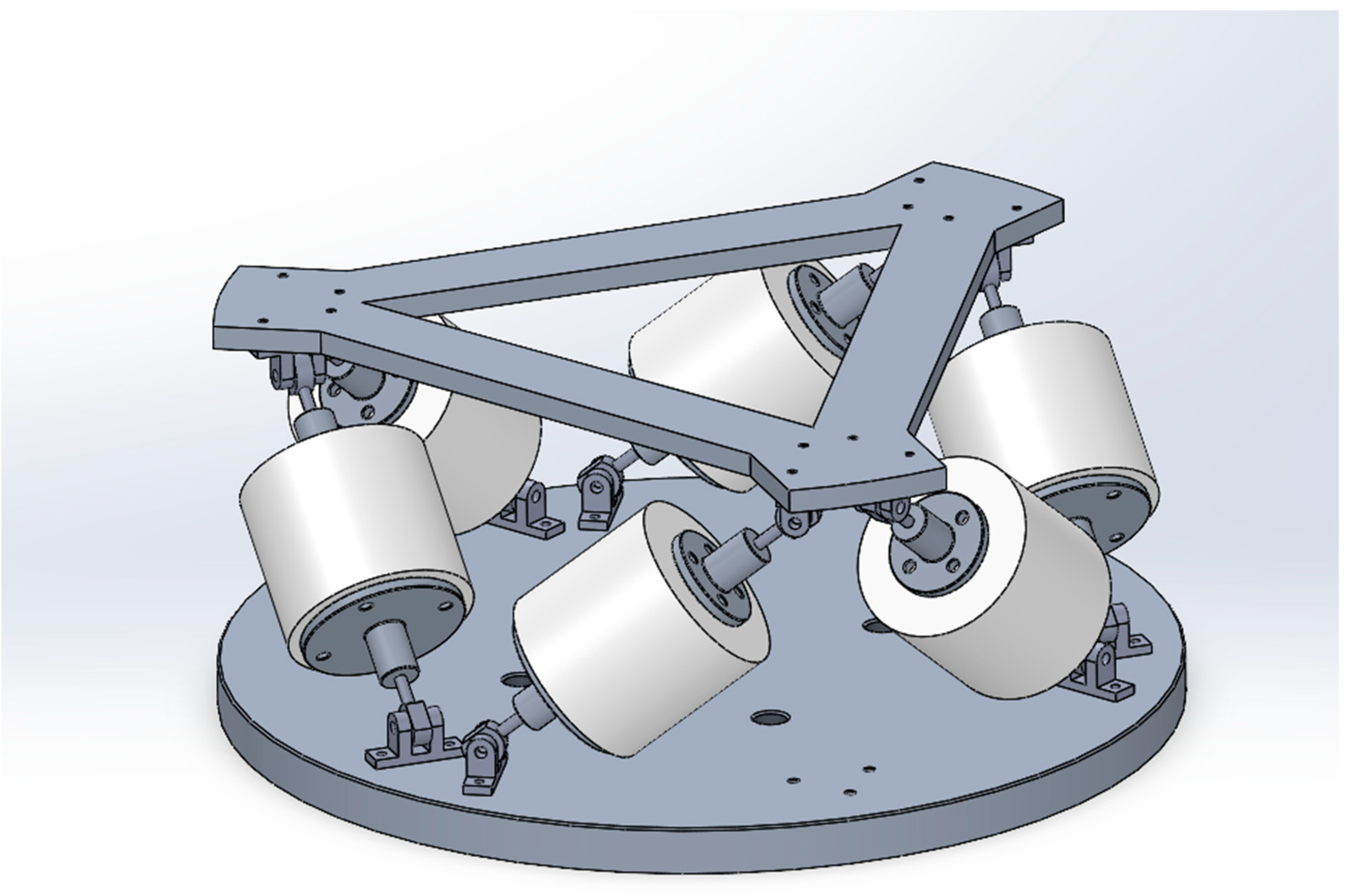
2.2. Platform
3. Modeling of the Vibration Isolation Structure
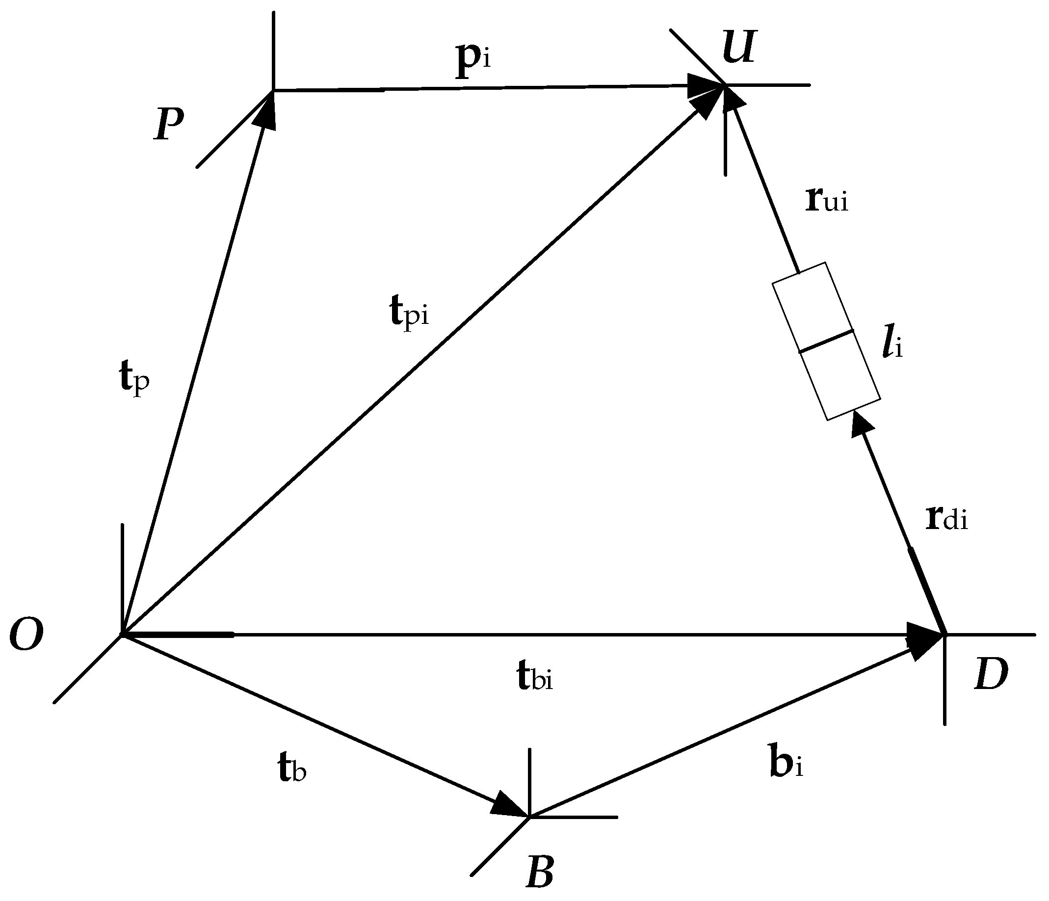
3.1. Reference Frames Definitions
3.2. Kinematics and Dynamics of the Legs
3.3. Differential Equation of Motion for the Payload Platform
4. Control System Design and Simulation Study
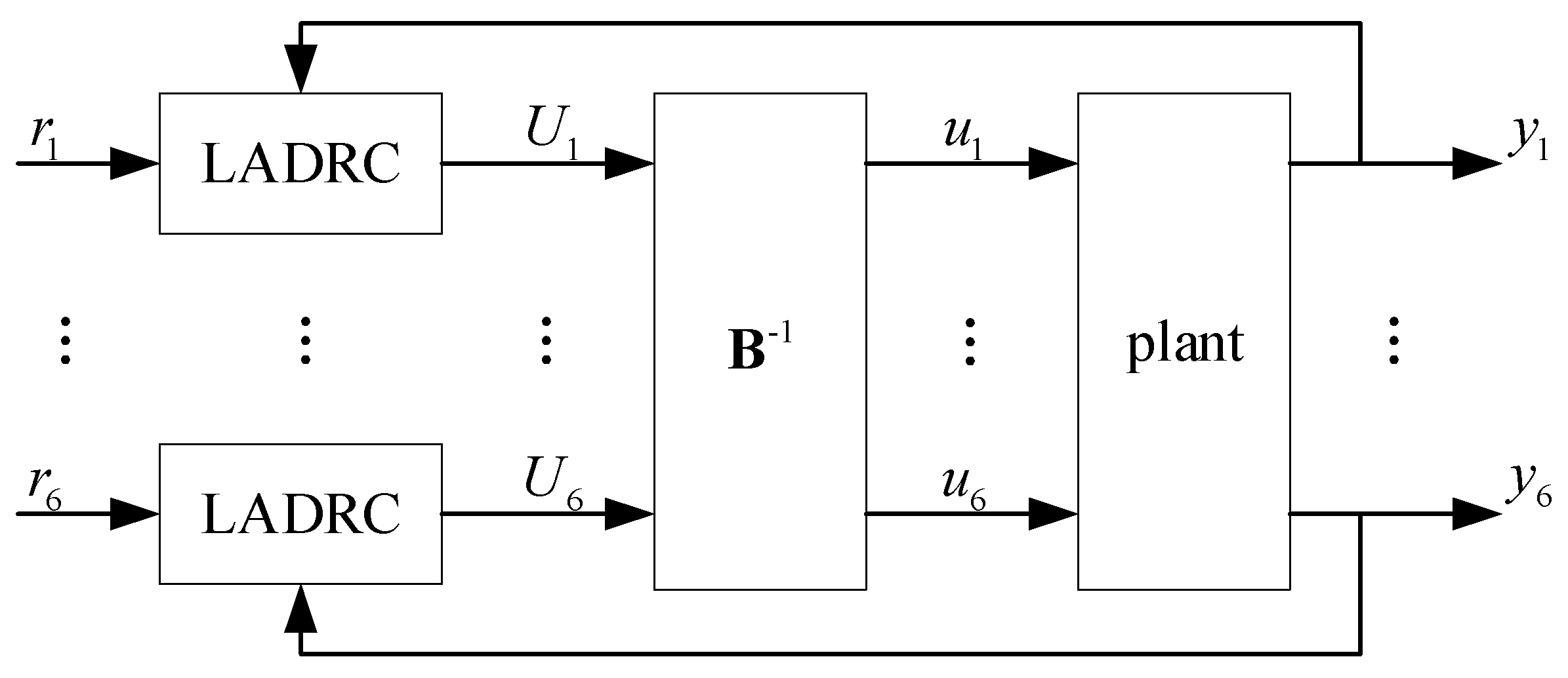
4.1. LADRC Design for the Stewart Platform
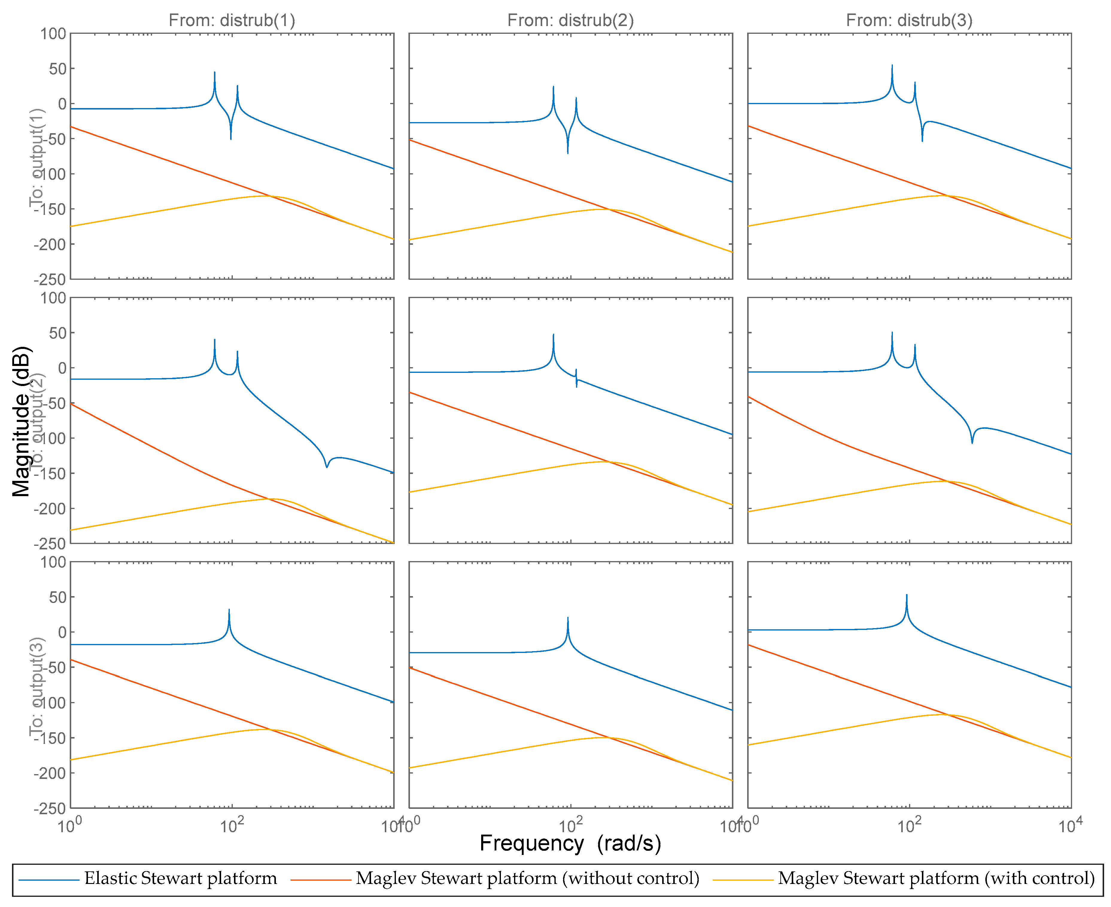
4.2. Numerical Simulation Studies
5. Conclusions
Author Contributions
Funding
Data Availability Statement
Conflicts of Interest
References
- Cao, D.Q.; Bai, K.C.; Ding, H.; Zhou, X.; Pan, Z.; Chen, L. Advances in dynamics and vibration control of large-scale flexible spacecraft. Chin. J. Theor. Appl. Mech. 2019, 51, 1–13. [Google Scholar]
- Zhang, Y.; Zang, Y.; Li, M.; Wang, Y.; Li, W. Active-passive integrated vibration control for control moment gyros and its application to satellites. J. Sound Vib. 2017, 394, 1–14. [Google Scholar] [CrossRef]
- Zhao, T.Y.; Ma, Y.; Zhang, H.Y.; Pan, H.G.; Cai, Y. Free vibration analysis of a rotating graphene nanoplatelet reinforced pre-twist blade-disk assembly with a setting angle. Appl. Math. Model. 2021, 93, 578–596. [Google Scholar] [CrossRef]
- Zhao, T.Y.; Li, K.; Ma, H. Study on dynamic characteristics of a rotating cylindrical shell with uncertain parameters. Anal. Math. Phys. 2022, 12, 1–28. [Google Scholar] [CrossRef]
- Fuller, C.C.; Elliott, S.J.; Nelson, P.A. Active Control of Vibration; Academic Press: Cambridge, MA, USA, 1996. [Google Scholar]
- Preumont, A.; Francois, A.; Bossens, F.; Abu-Hanieh, A. Force feedback versus acceleration feedback in active vibration isolation. J. Sound Vib. 2002, 257, 605–613. [Google Scholar] [CrossRef]
- Stewart, D. A platform with six degrees of freedom. Proc. Inst. Mech. Eng. 1965, 180, 371–386. [Google Scholar] [CrossRef]
- Geng, Z.J.; Haynes, L.S. Six degree-of-freedom active vibration control using the Stewart platforms. IEEE Trans. Control. Syst. Technol. 1994, 2, 45–53. [Google Scholar] [CrossRef]
- Wu, Y.; Yu, K.P.; Jiao, J.; Chi, W.; Tang, J. Dynamic isotropy design and analysis of a six-DOF active micro-vibration isolation manipulator on satellites. Robot. Comput.-Integr. Manuf. 2018, 49, 408–425. [Google Scholar] [CrossRef]
- Chi, W.; Ma, S.; Sun, J. A hybrid multi-degree-of-freedom vibration isolation platform for spacecrafts by the linear active disturbance rejection control. Appl. Math. Mech. 2020, 41, 805–818. [Google Scholar] [CrossRef]
- Zhu, T.; Cazzolato, B.; Robertson, W.S.P.; Zander, A. Vibration isolation using six degree-of-freedom quasi-zero stiffness magnetic levitation. J. Sound Vib. 2015, 358, 48–73. [Google Scholar] [CrossRef]
- Kim, M.; Kim, H.; Gweon, D.-G. Design and optimization of voice coil actuator for six degree of freedom active vibration isolation system using Halbach magnet array. Rev. Sci. Instrum. 2012, 83, 105117. [Google Scholar] [CrossRef] [PubMed]
- Long, Z.-Q.; Hao, A.-M.; Chen, G.; Long, Z. The research of active isolation platform with magnetically levitated control. J. Astronaut. 2003, 24, 510–514. [Google Scholar]
- Shi, W.; Liu, K.; Zhao, W. Active Vibration Isolation of a Maglev Inertially Stabilized Platform Based on an Improved Linear Extended State Observer. IEEE Access 2021, 9, 743–751. [Google Scholar] [CrossRef]
- Gáspár, P.; Szászi, I.; Bokor, J. Robust control design for mechanical systems using the mixed μ synthesis. Period. Polytech. Transp. Eng. 2003, 30, 37–52. [Google Scholar]
- Zhang, X.; Shao, C.; Li, S.; Xu, D.; Erdman, A. Robust H∞ vibration control for flexible linkage mechanism systems with piezoelectric sensors and actuators. J. Sound Vib. 2001, 243, 145–155. [Google Scholar] [CrossRef]
- Gao, Z.Q. Scaling and bandwidth-parameterization based controller tuning. In Proceedings of the American Control Conference, Denver, CO, USA, 4–6 June 2003; pp. 4989–4996. [Google Scholar]
- Zhao, S.; Gao, Z. An Active Disturbance Rejection Based Approach to Vibration Suppression in Two-Inertia Systems. Asian J. Control. 2013, 15, 350–362. [Google Scholar] [CrossRef] [Green Version]


| Specification | Value |
|---|---|
| Payload mass | 4.85 kg |
| Top platform mass | 3.29 kg |
| Base platform radius | 0.165 m |
| Platform height | 0.079 m |
| Leg length | 0.162 m |
| Leg length variation range | ±0.01 m |
| Top platform moment of inertia |
Publisher’s Note: MDPI stays neutral with regard to jurisdictional claims in published maps and institutional affiliations. |
© 2022 by the authors. Licensee MDPI, Basel, Switzerland. This article is an open access article distributed under the terms and conditions of the Creative Commons Attribution (CC BY) license (https://creativecommons.org/licenses/by/4.0/).
Share and Cite
Ma, H.; Chi, W.; Wang, C.; Luo, J. Design of a Maglev Stewart Platform for the Microgravity Vibration Isolation. Aerospace 2022, 9, 514. https://doi.org/10.3390/aerospace9090514
Ma H, Chi W, Wang C, Luo J. Design of a Maglev Stewart Platform for the Microgravity Vibration Isolation. Aerospace. 2022; 9(9):514. https://doi.org/10.3390/aerospace9090514
Chicago/Turabian StyleMa, He, Weichao Chi, Caihua Wang, and Jia Luo. 2022. "Design of a Maglev Stewart Platform for the Microgravity Vibration Isolation" Aerospace 9, no. 9: 514. https://doi.org/10.3390/aerospace9090514
APA StyleMa, H., Chi, W., Wang, C., & Luo, J. (2022). Design of a Maglev Stewart Platform for the Microgravity Vibration Isolation. Aerospace, 9(9), 514. https://doi.org/10.3390/aerospace9090514