
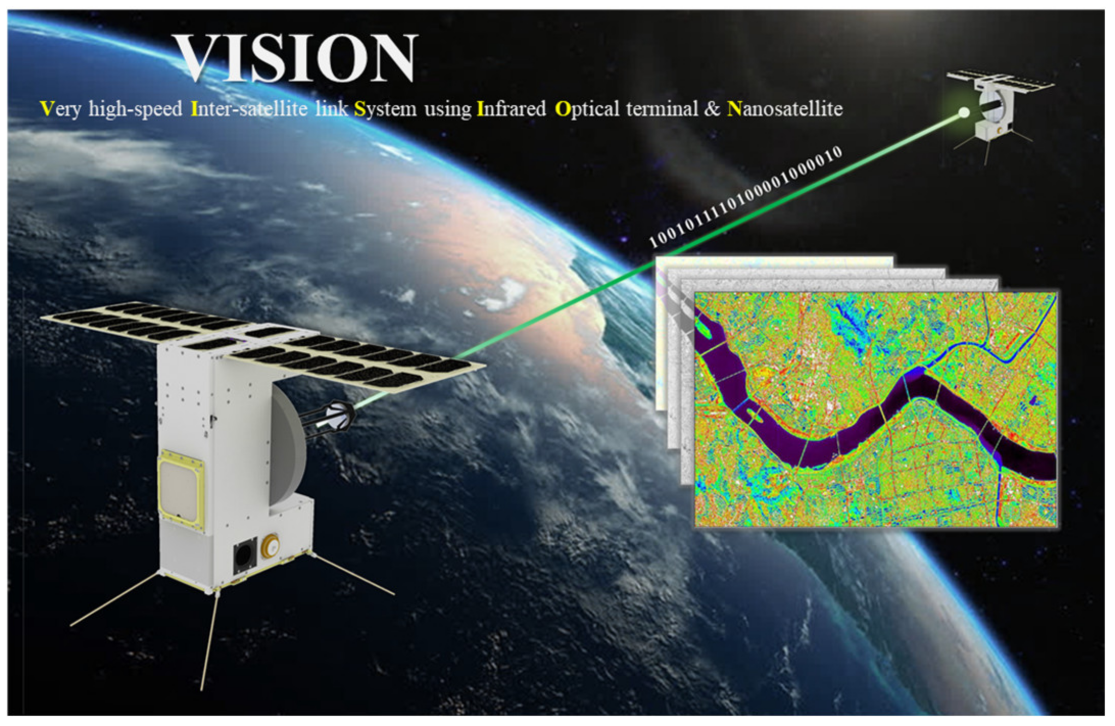
Design of Novel Laser Crosslink Systems Using Nanosatellites in Formation Flying: The VISION

 , ,
, , 
Abstract
:1. Introduction
2. Laser Crosslink Mission
2.1. Mission Statement
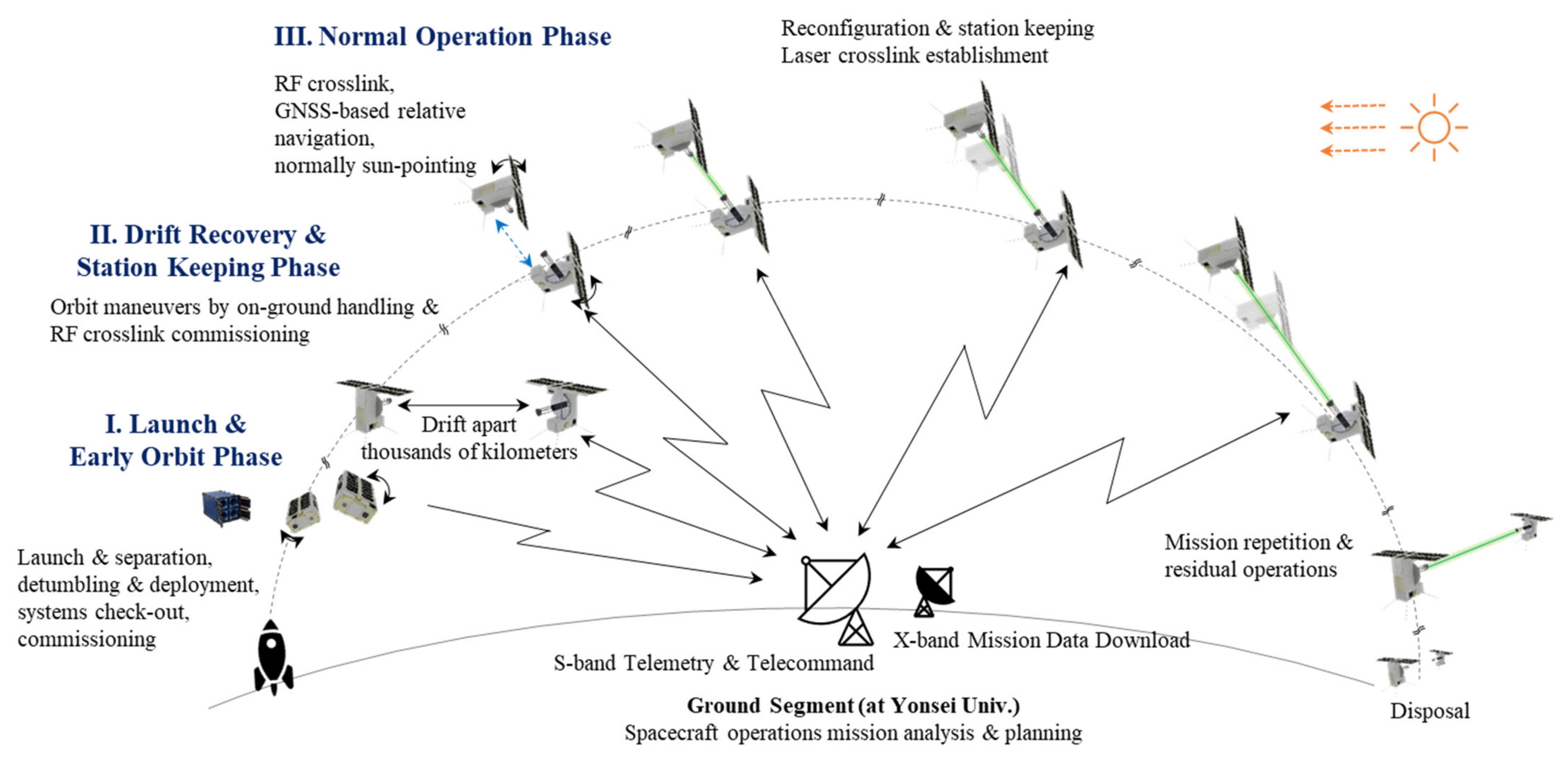
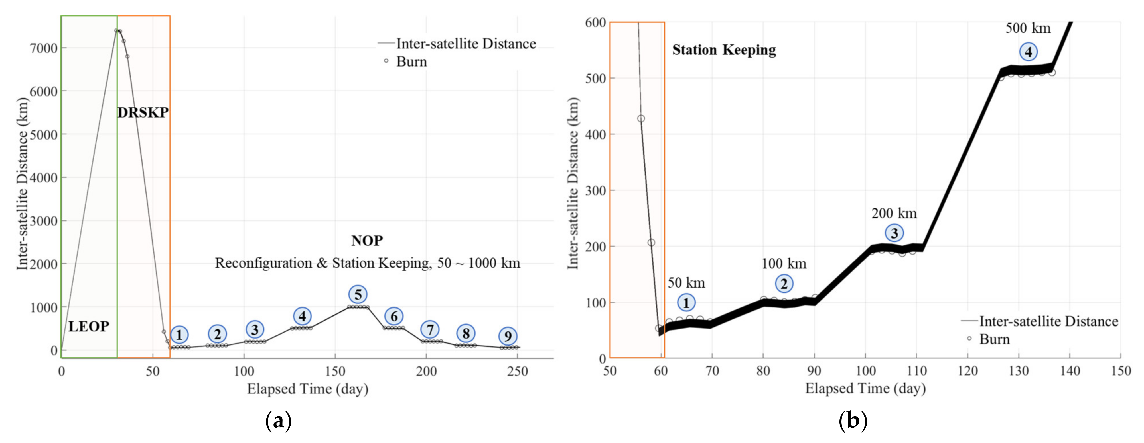
2.2. Orbit Scenarios
2.2.1. Phase I—Launch and Early Orbit Phase (LEOP)
2.2.2. Phase II—Drift Recovery and Station-Keeping Phase (DRSKP)
2.2.3. Phase III—Normal Operation Phase (NOP)
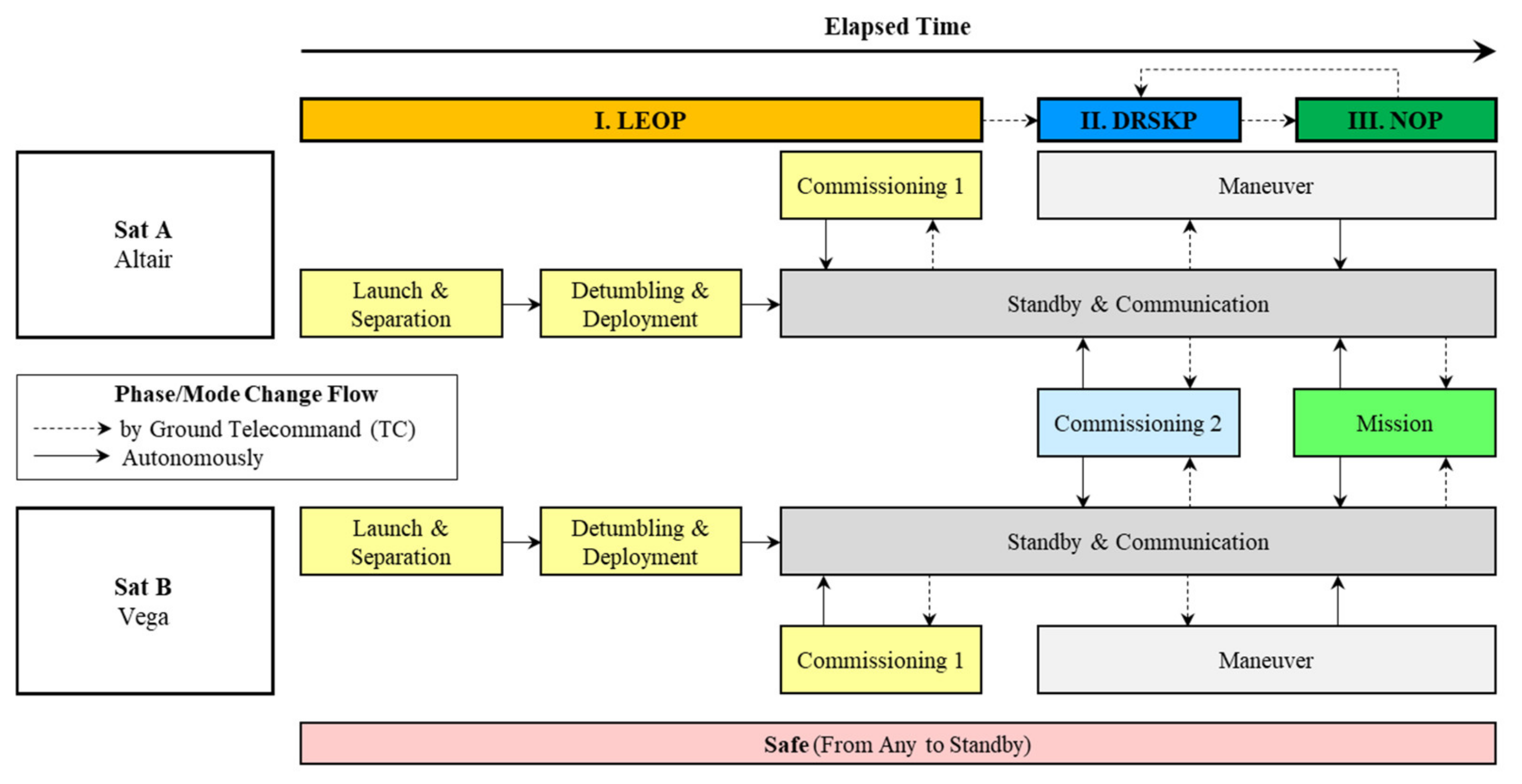
2.2.4. Operation Modes
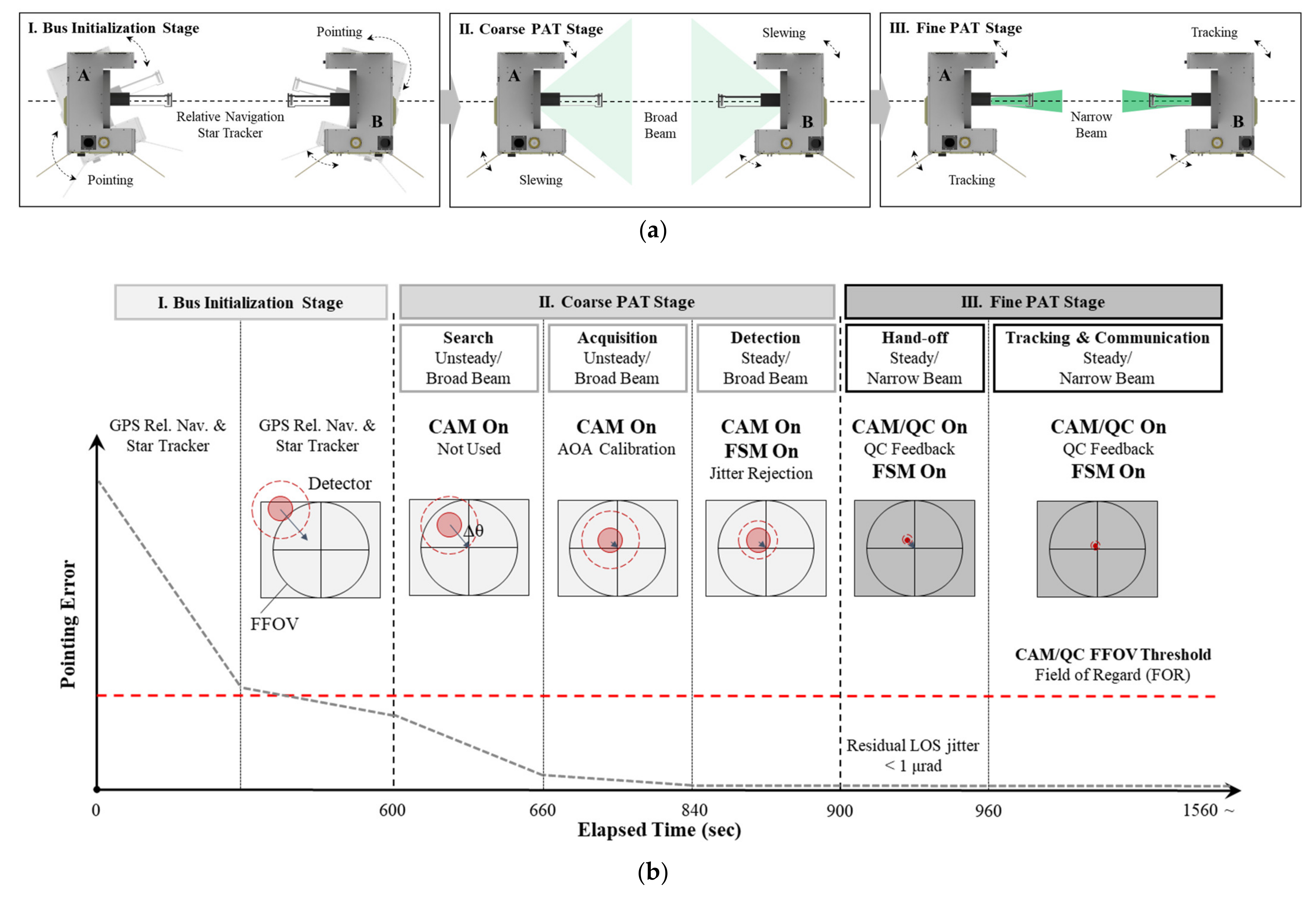
2.3. Pointing, Acquisition, and Tracking (PAT) Sequence
3. Concept of the Laser Crosslink Systems
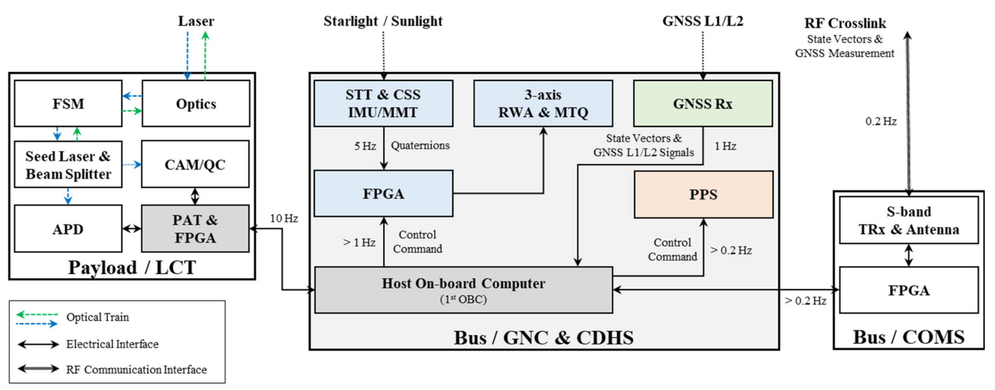
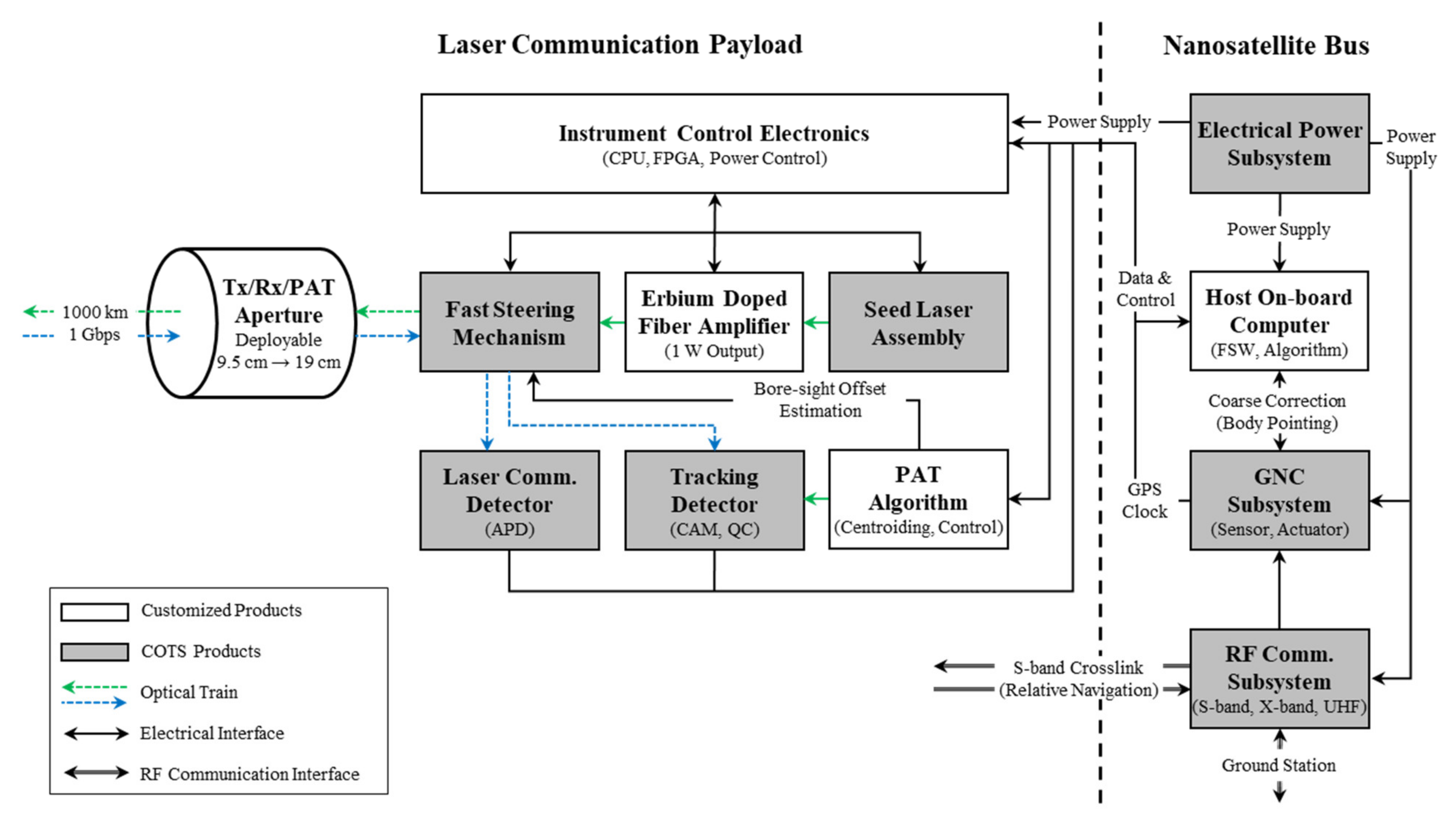
3.1. Systems Architecture
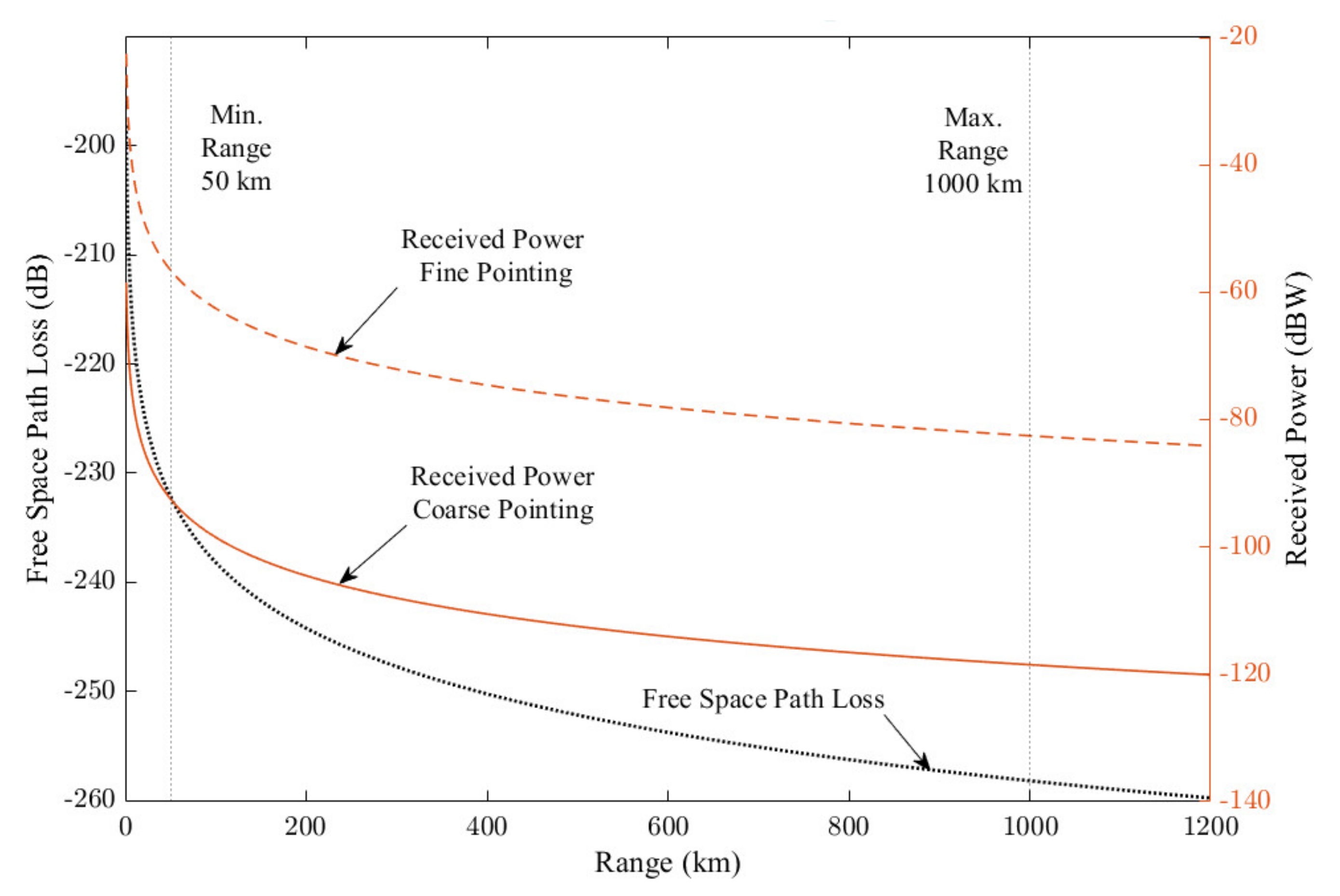
3.2. Optical Link Budget
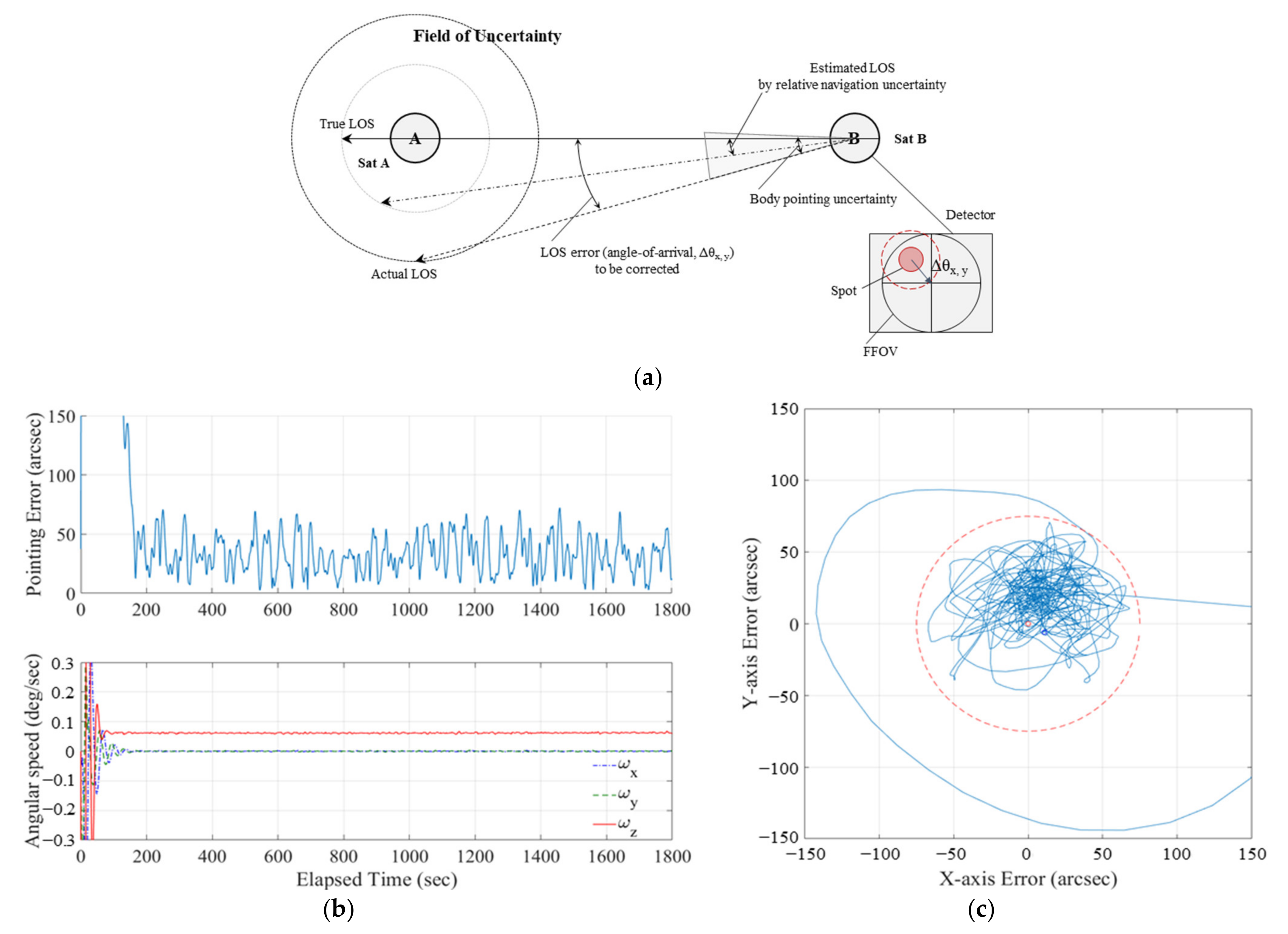
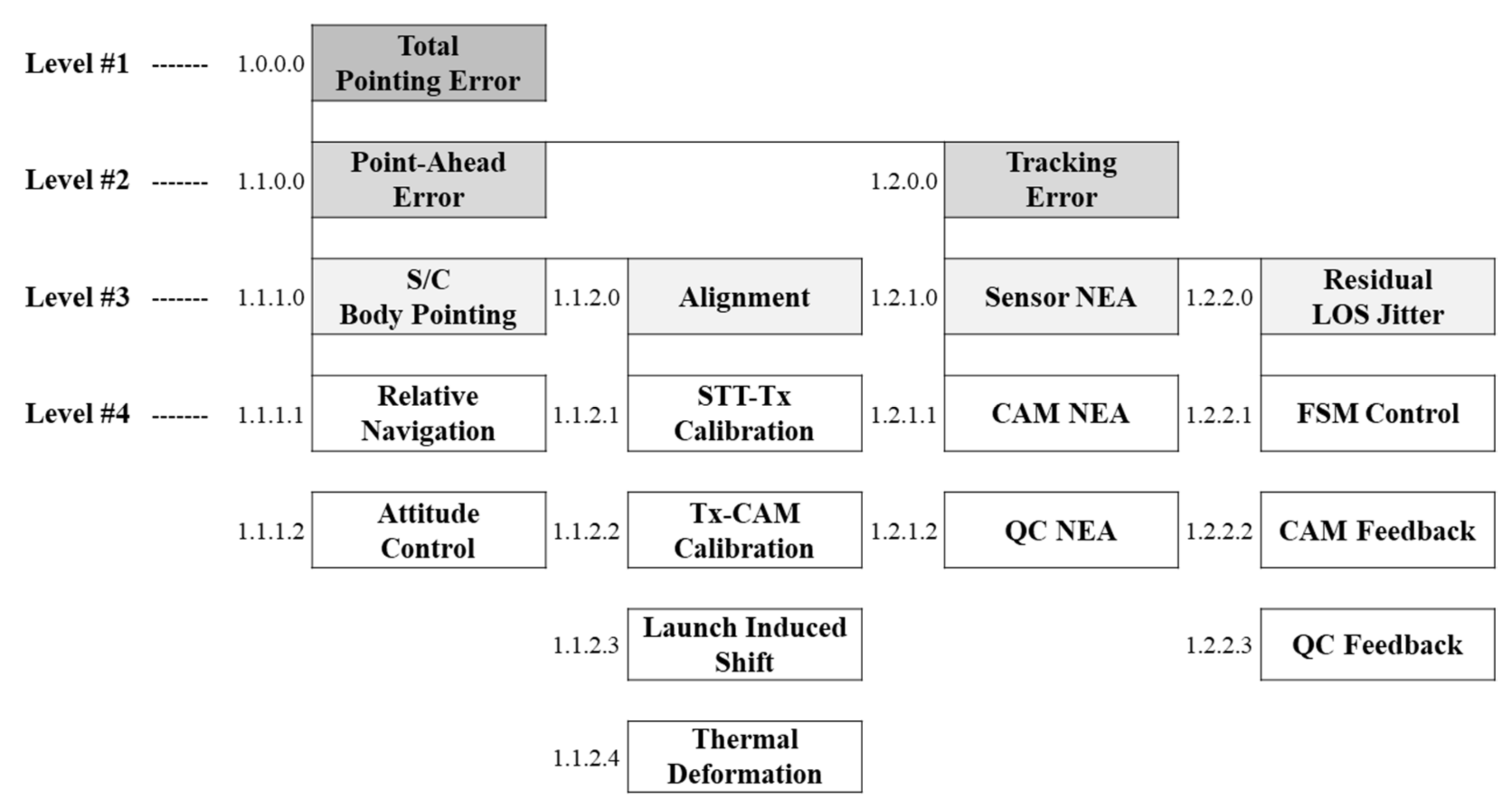
3.2.1. Pointing Error Budget
3.2.2. Signal-to-Noise Ratio Margin
3.3. Systems Design Specifications
4. Laser Crosslink Payload
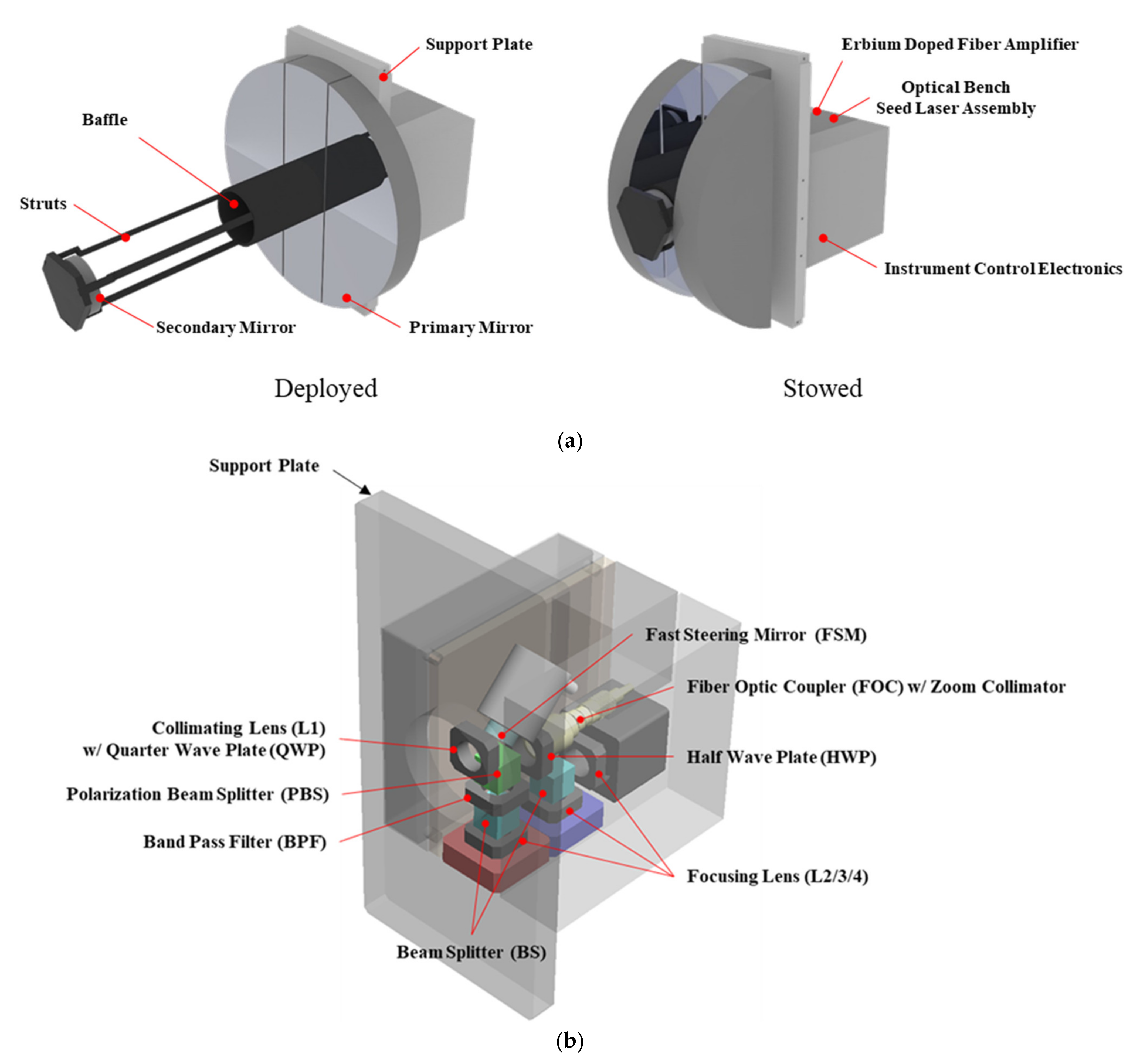
4.1. Payload Architecture
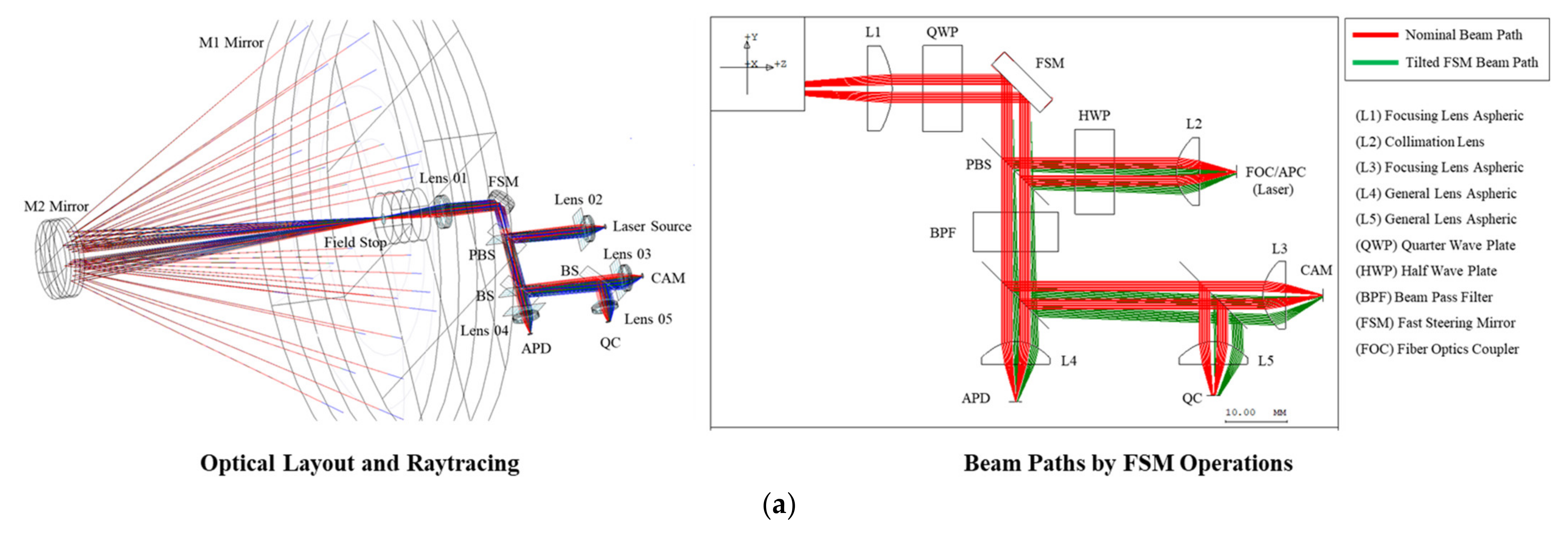
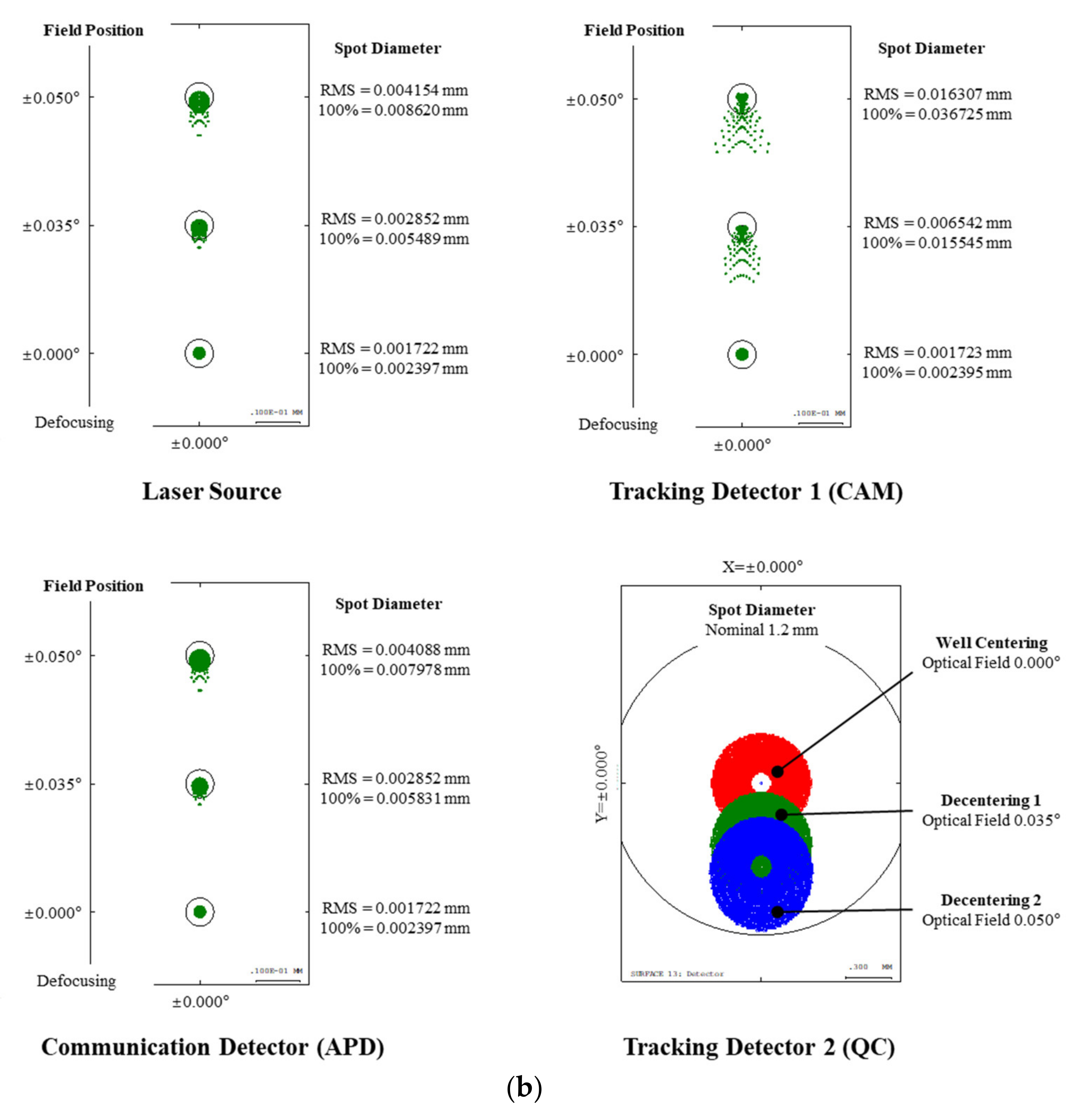
4.2. Optomechanical and Electronics Design
4.3. PAT Algorithm
5. Formation Flying Nanosatellite Bus
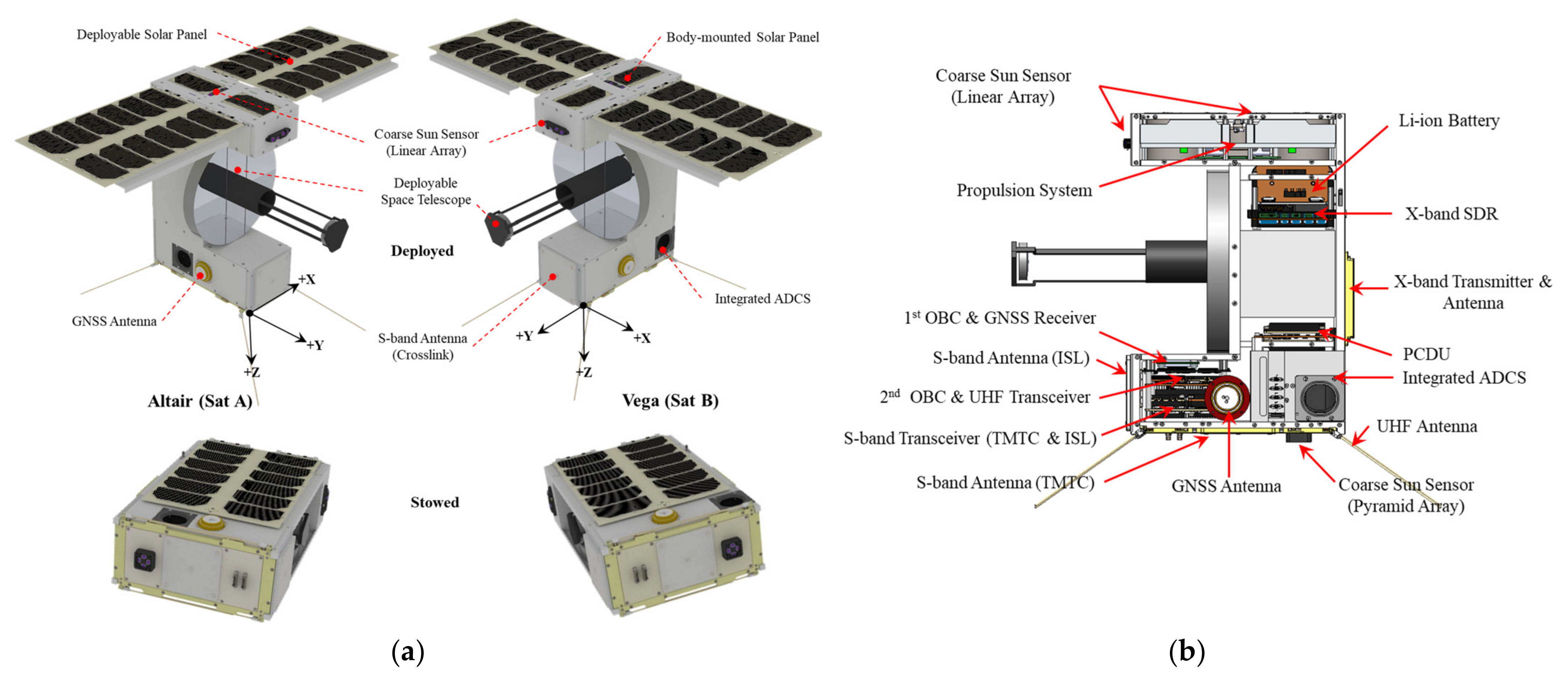
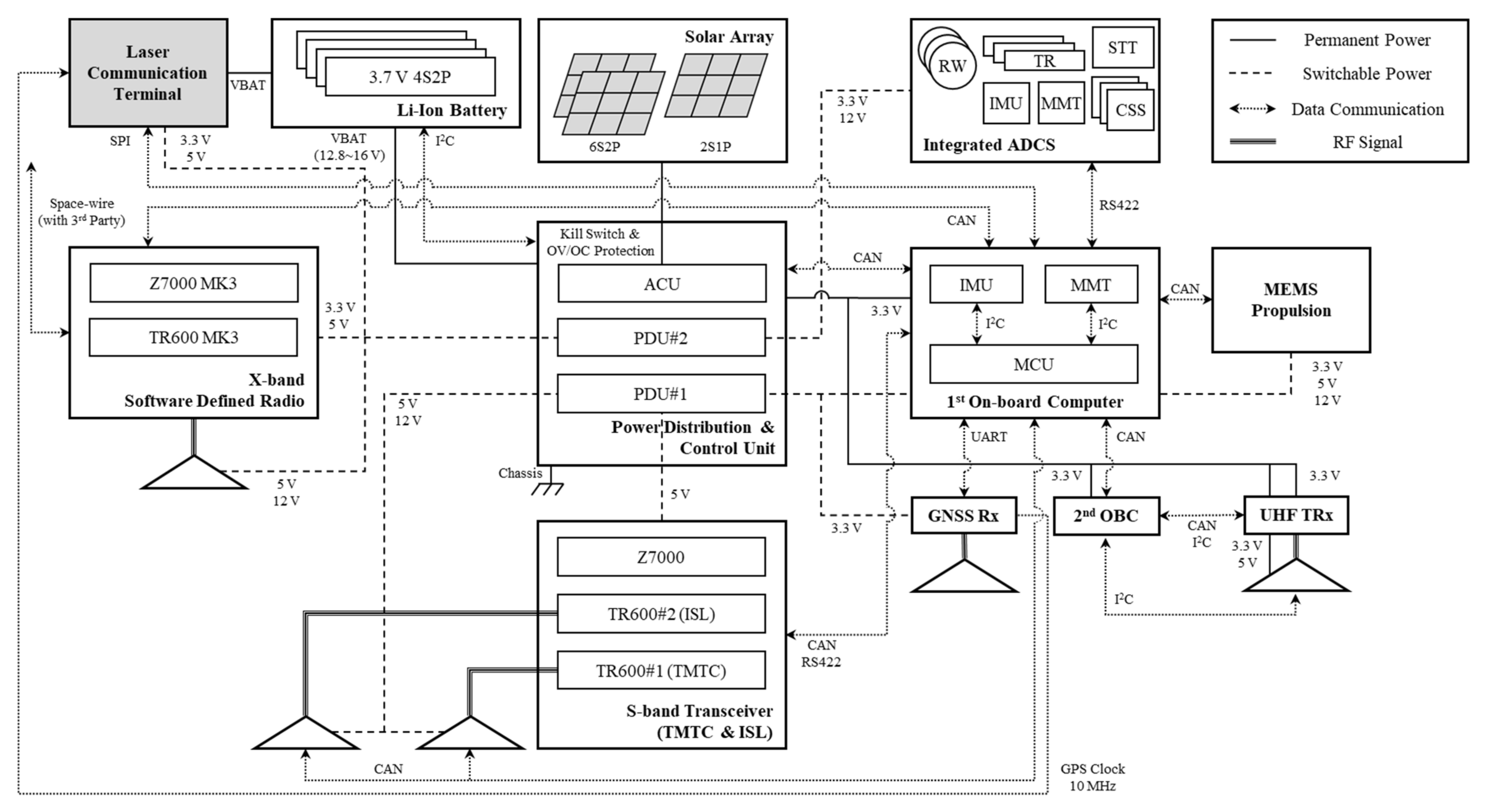
5.1. Bus Architecture
5.2. Subsystems Design
5.2.1. Guidance, Navigation, and Control Subsystem (GNC)
5.2.2. Electrical Power Subsystem (EPS)
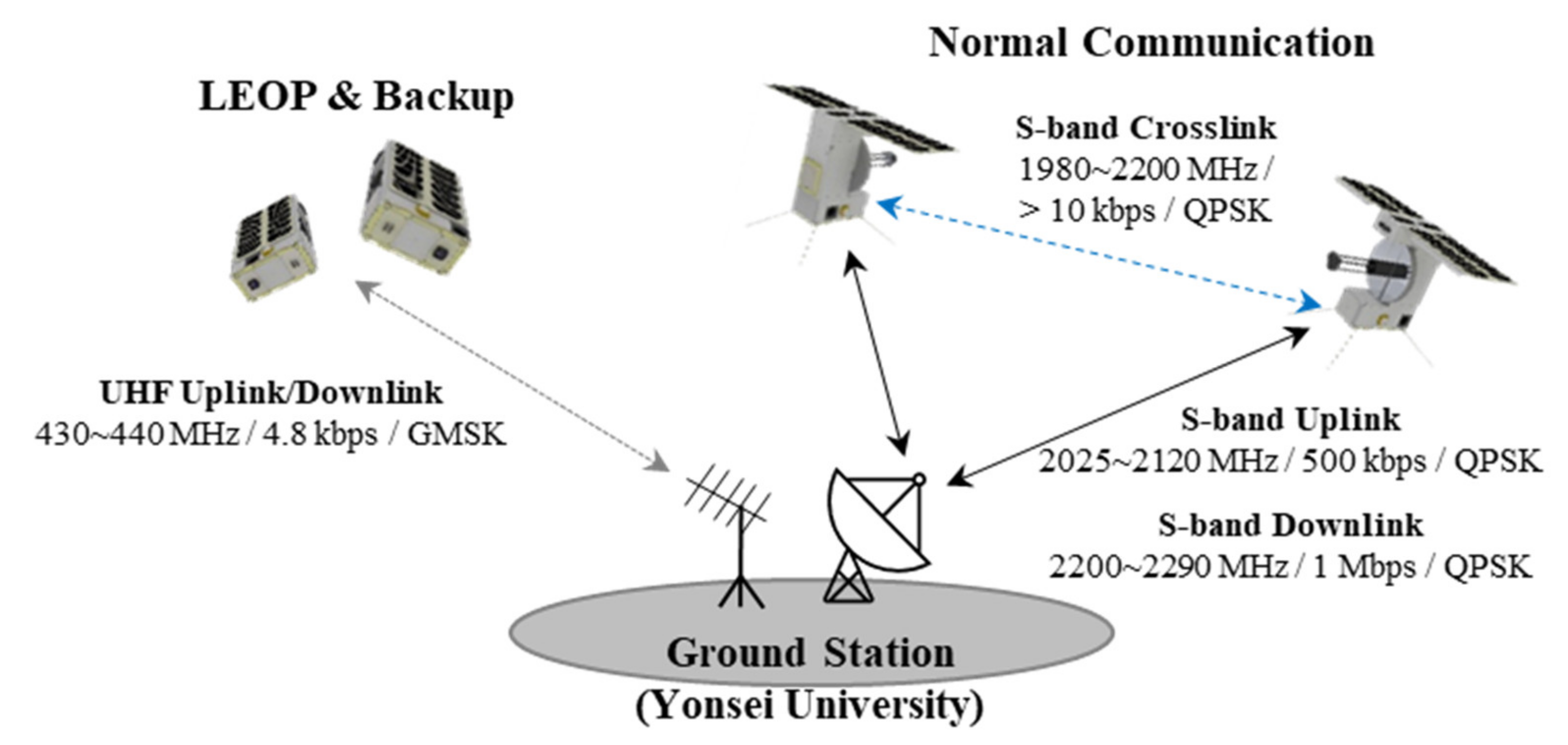
5.2.3. Communication Subsystem (COMS)
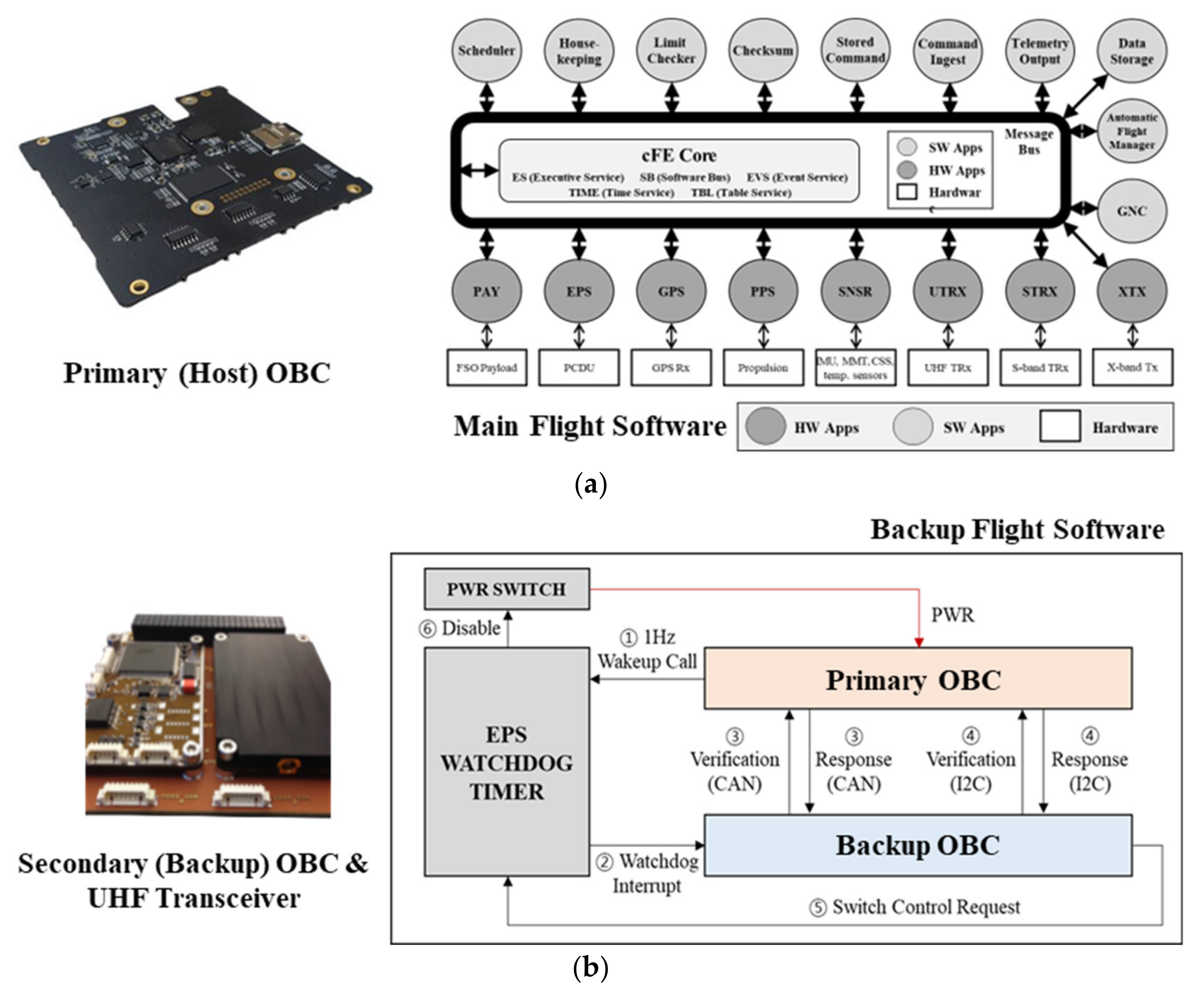
5.2.4. Command and Data-Handling Subsystem (CDHS)
5.2.5. Structure and Mechanism Subsystem (SMS)
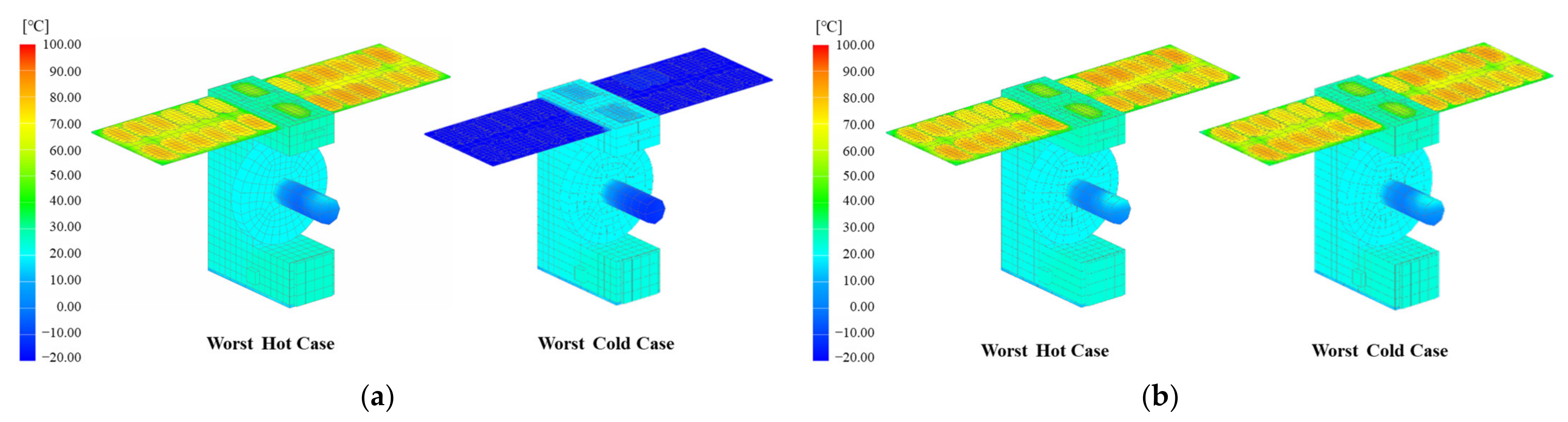
5.2.6. Thermal Control Subsystem (TCS)
6. Conclusions
Author Contributions
Funding
Institutional Review Board Statement
Informed Consent Statement
Data Availability Statement
Conflicts of Interest
References
- Kaushal, H.; Jain, V.K.; Kar, S. Free Space Optical Communication; Springer: New Delhi, India, 2017. [Google Scholar]
- Long, M.J. Pointing Acquisition and Tracking Design and Analysis for CubeSat Laser Communication Crosslinks. Master’s Thesis, Massachusetts Institute of Technology, Cambridge, MA, USA, 2018. [Google Scholar]
- Kaushal, H.; Kaddoum, G. Optical Communication in Space: Challenges and Mitigation Techniques. IEEE Commun. Surv. Tut. 2017, 19, 57–96. [Google Scholar] [CrossRef] [Green Version]
- Cahoy, K.; Grenfell, P.; Crews, A.; Long, M. The CubeSat Laser Infrared CroslinK Mission (CLICK). In Proceedings of the International Conference on Space Optics, Chania, Greece, 9–12 October 2018. [Google Scholar]
- Well, R.; Utter, A.; Rose, T.; Fuller, J.; Gates, K.; Oakes, B.; Janson, S. A CubeSat-Based Optical Communication Network for Low Earth Orbit. In Proceedings of the 31st Annual Small Satellite Conference, Logan, UT, USA, 7–10 August 2017. [Google Scholar]
- Leboffe, E.; Howard, T.; Freeman, A.; Robie, D. Multi-Mission Capable 1550 nm Lasercom Terminal for Space Applications. In Proceedings of the SPIE LASE, San Francisco, CA, USA, 1–6 February 2017. [Google Scholar]
- Newman, J.Z. Drift Recovery and Station Keeping for the CanX-4 & CanX-5 Nanosatellite Formation Flying Mission. Master’s Thesis, University of Toronto, Toronto, ON, USA, 2015. [Google Scholar]
- Leon, L.; Koch, P.; Walker, R. GOMX-4—The Twin European Mission for IOD Purposes. In Proceedings of the 32nd Annual Small Satellite Conference, Logan, UT, USA, 4–9 August 2018. [Google Scholar]
- Kim, G.N.; Park, S.Y.; Lee, T.; Kang, D.E.; Jeon, S.; Son, J.; Kim, N.; Park, Y.K.; Song, Y. Development of CubeSat Systems in Formation Flying for the Solar Science Demonstration: The CANYVAL-C Mission. Adv. Space Res. 2021, 68, 4434–4455. [Google Scholar] [CrossRef]
- Dresscher, M.; Korevaar, C.W.; van der Valk, N.C.J.; de Lange, T.J.; Saathof, R.; Doelman, N.; Crowcombe, W.E.; Duque, C.M.; de Man, H.; Human, J.D.; et al. Key Challenges and Results in the Design of Cubesat Laser Terminals, Optical Heads and Coarse Pointing Assemblies. In Proceedings of the 2019 IEEE International Conference on Space Optical Systems and Applications (ICSOS), Portland, OR, USA, 14–16 October 2019; pp. 1–6. [Google Scholar] [CrossRef]
- Song, Y.; Park, S.Y.; Kim, G.N.; Kim, D.G. Design of Orbit Controls for a Multiple CubeSat Mission Using Drift Rate Modulation. Aerospace 2021, 8, 323. [Google Scholar] [CrossRef]
- Schwartz, N.; Brzozowski, W.; Milanova, M.; Morris, K.; Todd, S.; Ali, Z.; Sauvage, J.F.; Ward, A.; Lunney, D.; MacLeod, D. High-Resolution Deployable CubeSat Prototype. In Proceedings of the SPIE Space Telescopes and Instrumentation, Virtual, 14–22 December 2020. [Google Scholar]
- Leung, S.; Montenbruck, O. Real-time navigation of formation flying spacecraft using global-positioning-system measurement. J. Guid. Control Dynam. 2005, 28, 226–235. [Google Scholar] [CrossRef]
- Grenfell, P.; Serra, P.; Cierny, O.; Kammere, W.; Gunnison, G.; Kusters, J.; Payne, C.; Cahoy, K. Design and Prototyping of a Nanosatellite Laser Communications Terminal for the CubeSat Laser Infrared CrosslinK (CLICK) B/C Mission. In Proceedings of the 34th Annual Small Satellite Conference, Logan, UT, USA, 1–6 August 2020. [Google Scholar]
- Holliday, M.; Manchester, Z.; Senesky, D.G. On-Orbit Implementation of Discrete Isolation Schemes for Improved Reliability of Serial Communication Buses. IEEE Trans. Aerosp. Electron. Syst. 2022, 1. [Google Scholar] [CrossRef]
- Shields, J.; Pong, C.; Lo, K.; Jones, L.; Mohan, S.; Marom, C.; McKinley, I.; Wilson, W.; Andrade, L. Characterization of CubeSat Reaction Wheel Assemblies. J. Small Sat. 2017, 6, 565–580. [Google Scholar]
- Montenbruck, O.; Eberhard, G. Ionospheric Correction for GPS Tracking of LEO Satellites. J. Navig. 2002, 55, 293–304. [Google Scholar] [CrossRef] [Green Version]


| Identification | Description |
|---|---|
| TMR.001 | Mission lifetime shall be longer than 12 months. |
| TMR.002 | The laser crosslink shall be established for the inter-satellite distance up to 1000 km. |
| TMR.003 | The data capacity shall be faster than 1 Gbps at 1 × 10⁻³ of uncoded BER and 1 × 10⁻⁹ of coded BER. |
| TMR.004 | A precision of residual line-of-sight jitters shall be smaller than 1 μrad while the laser crosslink is established. |
| TMR.005 | Entire laser crosslink systems shall be contained in the 6U nanosatellite platforms |
| Contents | Coarse PAT Stage (CPS) | Fine PAT Stage (FPS) | |||
|---|---|---|---|---|---|
| Substage | Search | Acquisition | Detection | Hand-Off | Tracking and Communication |
| Control Duration [sec] | ~60 | ~180 | ~60 | ~60 | >600 |
| Pointing Error (μ, σ) (1) [μrad] | <(1200, 400) | <(30, 1) | |||
| Bus Operation Attitude Control | Slewing | AOA Correction | Slewing | Slewing | |
| RF Crosslink | Enabled/ Relative Navigation | Enabled/ Relative Navigation | |||
| LCT Operation Beam | Broad/Unsteady | Broad/Steady | Narrow/Steady | ||
| Actuator | FSM On | FSM On | |||
| Detector | CAM On/ Unavailable | CAM On/ Available | QC (CAM (2)) On/ Available | ||
| Optical Link Budget Case | PAT#1 | PAT#2 | PAT#3 | PAT#4 | COM#1 |
| Pointing Error | PAT#1 (μ, σ) [μrad] | PAT#2 (μ, σ) [μrad] | PAT#3 (μ, σ) [μrad] | PAT#4 and COM#1 (μ, σ) [μrad] | |||||
|---|---|---|---|---|---|---|---|---|---|
| Elements | 50 km | 1000 km | 50 km | 1000 km | 50 km | 1000 km | 50 km | 1000 km | |
| Point-Ahead | Body Pointing | (386.76, 171.67) | (310.61, 109.99) | (384.79, 171.67) | (307.86, 109.99) | (0.33, 2.42) | (6.67, 2.43) | ||
| Alignment | (223.21, 173.40) | (223.21, 173.40) | (223.21, 173.37) | (223.21, 173.37) | (0.00, 173.21) | (0.00, 173.21) | |||
| Tracking | Sensor Noise | (0.00, 0.40) | (0.00, 8.00) | (0.00, 0.40) | (0.00, 8.00) | (0.00, 0.10) | (0.00, 0.60) | ||
| Residual Jitter | (0.00, 4.00) | (0.00, 4.00) | (0.10, 4.06) | (0.10, 4.06) | (0.10, 0.76) | (0.10, 0.76) | |||
| Total | (609.96, 244.00) | (533.82, 205.34) | (608.00, 244.02) | (531.06, 205.51) | (0.43, 173.27) | (6.77, 173.45) | (0.10, 0.77) | (0.10, 0.97) | |
| (a) PAT#1 and PAT#2—Search and Acquisition | ||||
| Elements | Budget | Available | Unit | Remarks |
| Tx Power | >−3 | 0.00 | dBW | 1 W output |
| Tx Gain | >56 | 56.98 | dB | Beam divergence, 8011.4 μrad |
| Pointing Loss | >−5 | −0.68 | Pointing error at Table 3 | |
| Tx Optics Loss | >−7 | −2.00 | Front-end, back-end optics | |
| Path Loss | <−259 | −258.18 | 1000 km apart | |
| Rx Gain | >111 | 111.71 | Clear aperture diameter, 19 cm | |
| Rx Optics Loss | >−7 | −7.00 | Max. tracking sensor (CAM) | |
| Rx Power | >−125 | −119.17 | dBW | Beam split, 99:1 |
| SNR Margin | >10 | 11.49 | dB | - |
| (b) PAT#3—Detection | ||||
| Elements | Budget | Available | Unit | Remarks |
| Tx Power | >−3 | 0.00 | dBW | 1 W output |
| Tx Gain | >56 | 56.98 | dB | Beam divergence, 8011.4 μrad |
| Pointing Loss | >−5 | −0.19 | Pointing error at Table 3 | |
| Tx Optics Loss | >−7 | −2.00 | Front-end, back-end optics | |
| Path Loss | <−259 | −258.18 | Max. range, 1000 km | |
| Rx Gain | >111 | 111.71 | Clear aperture diameter, 19 cm | |
| Rx Optics Loss | >−7 | −7.00 | Max. tracking sensor (CAM) | |
| Rx Power | >−125 | −118.69 | dBW | Beam split, 99:1 |
| SNR Margin | >10 | 11.81 | dB | - |
| (c) PAT#4—Hand-off and Tracking | ||||
| Elements | Budget | Available | Unit | Remarks |
| Tx Power | >−3 | 0.00 | dBW | 1 W output |
| Tx Gain | >56 | 92.92 | dB | Beam divergence, 127.8 μrad |
| Pointing Loss | >−5 | −0.03 | Pointing error at Table 3 | |
| Tx Optics Loss | >−7 | −2.00 | Front-end, back-end optics | |
| Path Loss | <−259 | −258.18 | Max. range, 1000 km | |
| Rx Gain | >111 | 111.71 | Clear aperture diameter, 19 cm | |
| Rx Optics Loss | >−7 | −7.00 | Max. tracking sensor (QC) | |
| Rx Power | >−125 | −82.58 | dBW | Beam split, 99:1 |
| SNR Margin | >10 | 22.21 | dB | - |
| (d) COM#1—Communication | ||||
| Elements | Budget | Available | Unit | Remarks |
| Tx Power | >−3 | 0.00 | dBW | 1 W output |
| Tx Gain | >56 | 92.92 | dB | Beam divergence, 127.8 μrad |
| Pointing Loss | >−5 | −0.03 | Pointing error at Table 3 | |
| Tx Optics Loss | >−7 | −2.00 | Front-end, back-end optics | |
| Path Loss | <−259 | −258.18 | Max. range, 1000 km | |
| Rx Gain | >111 | 111.71 | Clear aperture diameter, 19 cm | |
| Rx Optics Loss | >−7 | −3.50 | APD | |
| Rx Power | >−125 | −59.08 | dBW | Beam split, 99:1 |
| SNR Margin | >10 | 15.98 | dB | OOK signal and coded BER 1 × 10⁻³ |
| Parameter | Requirements | Specifications | Remarks | ||
|---|---|---|---|---|---|
| Physical Properties | Mass | Payload | <6 kg <6 kg | 5.70 kg 5.66 kg | wet mass |
| Bus | |||||
| Size | Payload | <0.25 × 0.10 × 0.10 m3 6U standard | <0.20 × 0.09 × 0.09 m3 <0.25 × 0.12 × 0.34 m3 | stowed | |
| Bus | |||||
| Orbit | Lifetime | >1 years | 3 years | radiation tolerance | |
| Altitude | 600 ± 25 km | 600 km | sun synchronous | ||
| LTAN | 18:00 ± 2 h | 18:00 h | - | ||
| Laser Crosslink | Range | Up to 1000 km | 50~1000 km | - | |
| Capacity | Up to 1 Gbps | 1 Gbps | uncoded BER 1 × 10⁻³ | ||
| Residual LOS Jitter (μ, σ) | <(30, 1) [μrad] | <(0.10, 0.96) [μrad] | fine pointing | ||
| SNR Margin | >10 dB | >15.98 dB | communication | ||
| GNC | Body Pointing | <75 arcsec (3σ) | <63.5 arcsec (3σ) | slewing, LOS error | |
| Stability | <5 arcsec (1σ) | <2 arcsec (1σ) | slewing, LOS jitter | ||
| Relative Navigation | <10 m (3σ) | <0.90 m (3σ) | each axis | ||
| Propellant | >5.2 m/s | 6.6 m/s | 10% of residual | ||
| Electrical Interface | Data Communication | 1 Mbps CAN, SPI | 1 Mbps CAN, SPI, UART, RS422, I2C | Ethernet, JTAG for debugging | |
| Power Supply | 3.3 V, 5 V, 12 V | 3.3 V, 5 V, 12 V, Battery Voltage | switchable, latch-up protection | ||
| RF Communication | S-band (TMTC/ISL) | >0.5 Mbps/5 kbps | 1 Mbps/10 kbps | margin > 7.01 dB | |
| X-band (Mission Data) | >100 Mbps | 90–135 Mbps | margin > 5.13 dB | ||
| UHF (Redundancy) | >2 kbps | 4.8–9.6 kbps | margin > 9.56 dB | ||
| Electrical Power | Generation (Average) | >16 W | >21.6 W | sun-pointing | |
| Peak Draw | <4 A (protected) | <1.68 A | laser crosslink | ||
| <10 A (unprotected) | <2.72 A | ||||
| Depth of Discharge | <20% | <18.5% | 77 Wh battery pack | ||
| Parameter | Specifications | Remarks | |
|---|---|---|---|
| Data Rate | 1 Gbps | at 1000 km | |
| Unassisted Pointing | <±637 μrad | body pointing (3σ) | |
| Coarse Assisted Pointing | <±329 μrad | jitter (3σ) | |
| Pointing Accuracy | <±1 μrad | residual jitter (1σ) | |
| Laser Communication Terminal | Size/Mass | <3U/<5.7 kg | (stowed) budget < 6 kg |
| Power Budget | <39.1 W | budget < 45 W | |
| Electrical Interface | 3.3 V, 5 V, bus VBAT (12.8-16 V) | <2.5 A (latch-up protection) | |
| SPI | optionally RS-422 | ||
| Tx Power | <1 W | 0 dBW | |
| Tx Wavelength | 1550 nm (C-band), 1570 nm (L-band) | ||
| Tx Beam Div. Angle | 8 mrad (CPS) and 128 μrad (FPS) | ||
| PAT Scheme | Hybrid open-/closed-loop | using laser beam | |
| Coarse PAT FOV | <±1745 μrad | focal plane array | |
| Fine PAT FOV | <±873 μrad | quad cell | |
| FSM FOR | <±1047 μrad | FSM spec. and optics design | |
| FSM Resolution | <0.5 μrad | FSM spec. and optics design | |
| Rx Aperture | Φ190 | deployable space telescope | |
| Modulation | On-off keying (OOK) | ||
| Range (km) | State | Relative Navigation Error (Mean, 3σ) | ||
|---|---|---|---|---|
| Radial | In-Track | Cross-Track | ||
| 50 | Position [cm] | 0.62 ± 11.50 | 0.03 ± 5.28 | 0.06 ± 11.59 |
| Velocity [cm/s] | 0.24 ± 0.84 | −0.00 ± 0.39 | 0.00 ± 0.58 | |
| 100 | Position [cm] | 0.85 ± 10.91 | −0.00 ± 5.57 | 0.03 ± 15.64 |
| Velocity [cm/s] | 0.48 ± 0.80 | −0.01 ± 0.41 | 0.00 ± 0.59 | |
| 200 | Position [cm] | 2.24 ± 12.70 | 0.01 ± 5.81 | 0.04 ± 25.09 |
| Velocity [cm/s] | 0.95 ± 0.94 | −0.01 ± 0.43 | 0.00 ± 0.64 | |
| 500 | Position [cm] | 5.06 ± 15.82 | −0.06 ± 5.80 | 0.69 ± 49.47 |
| Velocity [cm/s] | 2.39 ± 1.22 | −0.03 ± 0.45 | 0.01 ± 0.63 | |
| 1000 | Position [cm] | 10.53 ± 24.57 | 0.06 ± 6.30 | 0.35 ± 89.34 |
| Velocity [cm/s] | 4.79 ± 1.94 | −0.05 ± 0.53 | 0.02 ± 0.61 | |
| Scenario | Budget (m/s) | ΔV (m/s) | Attempt (Times) | Total ΔV (m/s) | Margin (%) |
|---|---|---|---|---|---|
| Drift Recovery | 3.0 | 2.55 | 1 | 2.55 | 15.0 |
| Station Keeping (1) | 0.5 | 0.38 | 1 | 0.38 | 24.0 |
| Reconfiguration | 2.5 | 0.11 | 20 | 2.20 | 12.0 |
| Residual and Disposal | 0.6 | 100.0 | |||
| Accumulated ΔV (m/s) | 6.6 | 5.13 | 22.3 |
| Parameter | Operation Scenarios | |||||
|---|---|---|---|---|---|---|
| LEOP (3) | Maneuver | Standby | Mission | Comm. | Safe | |
| Power Generation (W) | 5.81 | 17.31 | 21.64 | 17.31 | 17.31 | 21.64 |
| Power Consumption (W) | 3.56 | 9.29 | 5.81 | 16.24 | 9.70 | 4.47 |
| Discharge (Wh) | −7.18 | −16.64 | −11.71 | −26.67 | −17.37 | −9.01 |
| Charge (Wh) (1) | 3.14 | 13.17 | 19.76 | 13.17 | 13.17 | 19.76 |
| Margin (Wh) | −4.03 | −3.47 | 8.05 | −13.50 | −4.20 | 10.75 |
| Depth of Discharge (%) (2) | 5.51 | 4.75 | 18.45 | 5.74 | ||
| Elements | Unit | Downlink (1) | Uplink (1) | Crosslink (2) | |||
|---|---|---|---|---|---|---|---|
| UHF | S-Band | X-Band | UHF | S-Band | S-Band | ||
| Modulation | - | GMSK | QPSK | 8-PSK | GMSK | QPSK | QPSK |
| Frequency | MHz | 437.0 | 2200.0 | 8250.0 | 437.0 | 2100.0 | 2200.0 |
| Data Rate | Kbps | 4.8 | 1000.0 | 1,000,000.0 | 4.8 | 500.0 | 10.0 |
| Tx Power | W | 1.0 | 1.0 | 2.0 | 27.0 | 27.0 | 1.0 |
| Tx Gain | dBi | 0.0 | 8.0 | 13.0 | 18.9 | 36.0 | 8.0 |
| EIRP | dBm | 29.5 | 37.8 | 41.7 | 57.8 | 76.3 | 7.4 |
| Path Loss | dB | −153.2 | −163.1 | −169.5 | −153.2 | −162.7 | −160.1 |
| Rx Gain | dB | 18.9 | 36.0 | 51.0 | 0.0 | 8.0 | 8.0 |
| Eb/N0 | dB | 17.3 | 14.8 | 14.0 | 41.0 | 37.6 | 18.6 |
| Link Margin | dB | 9.6 | 7.0 | 4.2 | 33.2 | 29.8 | 6.7 |
| Subsystem | Operating Temperature (°C) | Worst Case Analysis (°C) | |||
|---|---|---|---|---|---|
| Min. | Max. | Min. | Max. | ||
| Payload | Laser Communication Terminal | −40 | +85 | 20.37 | 23.71 |
| GNC | Integrated ADCS | −20 | +50 | 21.32 | 22.61 |
| GNSS Antenna | −40 | +85 | 23.41 | 25.00 | |
| Propulsion | 0 | +50 | 20.33 | 25.40 | |
| CDHS | Primary OBC and GNSS Receiver | −40 | +85 | 24.28 | 25.70 |
| Secondary OBC and UHF Transceiver | −30 | +85 | 23.81 | 25.30 | |
| COMS | S-band SDR | −40 | +85 | 23.87 | 25.48 |
| S-band Antenna (TMTC) | −40 | +85 | 11.53 | 16.09 | |
| S-band Antenna (Crosslink) | −40 | +85 | 23.21 | 24.85 | |
| X-band SDR | −40 | +85 | 20.50 | 21.48 | |
| X-band Transmitter and Antenna | −40 | +57 | 20.38 | 22.42 | |
| UHF Antenna | −40 | +85 | 12.68 | 17.50 | |
| EPS | Solar Panel | −40 | +105 | −27.83 | 83.08 |
| PCDU | −35 | +85 | 21.35 | 22.40 | |
| Battery | 0 | +45 | 20.37 | 23.74 | |
Publisher’s Note: MDPI stays neutral with regard to jurisdictional claims in published maps and institutional affiliations. |
© 2022 by the authors. Licensee MDPI, Basel, Switzerland. This article is an open access article distributed under the terms and conditions of the Creative Commons Attribution (CC BY) license (https://creativecommons.org/licenses/by/4.0/).
Share and Cite
Kim, G.-N.; Park, S.-Y.; Seong, S.; Choi, J.-Y.; Han, S.-K.; Kim, Y.-E.; Choi, S.; Lee, J.; Lee, S.; Ryu, H.-G.; et al. Design of Novel Laser Crosslink Systems Using Nanosatellites in Formation Flying: The VISION. Aerospace 2022, 9, 423. https://doi.org/10.3390/aerospace9080423
Kim G-N, Park S-Y, Seong S, Choi J-Y, Han S-K, Kim Y-E, Choi S, Lee J, Lee S, Ryu H-G, et al. Design of Novel Laser Crosslink Systems Using Nanosatellites in Formation Flying: The VISION. Aerospace. 2022; 9(8):423. https://doi.org/10.3390/aerospace9080423
Chicago/Turabian StyleKim, Geuk-Nam, Sang-Young Park, Sehyun Seong, Jae-Young Choi, Sang-Kook Han, Young-Eon Kim, Suyong Choi, Joohee Lee, Sungmoon Lee, Han-Gyeol Ryu, and et al. 2022. "Design of Novel Laser Crosslink Systems Using Nanosatellites in Formation Flying: The VISION" Aerospace 9, no. 8: 423. https://doi.org/10.3390/aerospace9080423
APA StyleKim, G.-N., Park, S.-Y., Seong, S., Choi, J.-Y., Han, S.-K., Kim, Y.-E., Choi, S., Lee, J., Lee, S., Ryu, H.-G., & Kim, S. (2022). Design of Novel Laser Crosslink Systems Using Nanosatellites in Formation Flying: The VISION. Aerospace, 9(8), 423. https://doi.org/10.3390/aerospace9080423