1. Introduction
Slagging of surfaces of the convective heat exchange is a basic limitation for long-time work of boilers with maximal loading [
1]. Slagging leads to boiler efficiency reduction, and working costs rise because of periodical stops for de-slagging. That is why steam boilers burning solid or liquid fuel must be always equipped with systems of surface cleaning. There are different methods of the cleaning of heated surfaces, but up to now, there are still no reliable and effective methods to clean heated surfaces from ash deposits.
According to the references, the application of short-time impulse methods for surface cleaning by means of powerful gas jets is the major trend in the developed cleaning systems. In particular, at the end of the last century, extensive efforts were applied to perform theoretical and experimental investigations in the field of gas-impulse cleaning [
2,
3,
4,
5,
6,
7]. The main element of the gas-impulse cleaning system is an explosion chamber, its volume is up to 1 m
3, which is preliminarily filled with the mixture of a flammable gas (hydrogen, propane, methane) and air. As the chamber is filled, the mixture is ignited, and the jet of detonation combustion products with the pressure of 0.6–0.8 MPa is supplied through the duct with a diameter 100–200 mm in the specific area of the boiler and acts here on the heat exchange surfaces to be cleaned. This method has a number of disadvantages (explosion hazard, big sizes, etc.), which limits the field of its application.
The air-impact cleaning is more promising and multi-purpose. In this case, the impulse air jet is formed by an air-impact generator (AIG) [
8].
Figure 1 shows the typical diagram of the air impact generator for tubular heat exchanger cleaning. Compressed air with the pressure of 0.8–1 MPa is accumulated in the accumulating buffer, its volume is 0.02–0.05 m
3. At the given time, the fast valve opens (opening time 3–5 ms), and air is exhausted through the exhaust nozzle with a diameter of 100–150 mm, acting on the heat exchange surfaces to be cleaned.
Air-impact cleaning features a safe operation and a wide range of adjustments of the created action. Vast experience shows that for the cleaning of powerful boilers, the air-impact must satisfy the following requirements:
- -
quite big energy of the exhaust jet (minimum 250 kJ);
- -
low pressure of the process air (maximum 1 MPa);
- -
high reliability and simplicity of valve devices maintenance;
- -
protection of movable elements of the system from aggressive smoke gases in the boiler;
- -
low cost of manufacture and assembly of the system.
- -
engineering simplicity of actuation devices;
- -
low material capacity ad low energy demand;
- -
simple control and automatability.
The air-impact cleaning system is developed on the base of the analysis of the rate for formation and strength of expected depositions regarding the temperature modes of operation of the boiler and its units. Geometrical and construction peculiarities of the real boiler dictate the cleaning system configuration, amount, and position of air-impact generators, and auxiliary elements (ducts, service platforms, air and cable passages, etc.). To provide the qualitative cleaning of technological objects, the preventive cleaning is the most reasonable. The period of actuation of the air-impact cleaning system is 1–2 h, the control is performed by the fully automated control system.
First works on air-impact cleaning of heated surfaces in boilers were performed in UralVTI (Ural All-Russian Thermo-engineering Institute) [
9]. Since 1992, research of the applicability of air-impact devices for boiler cleaning was launched in the Institute of Theoretical and Applied Mechanics SB RAS (Novosibirsk). Here, systematic scientific and engineering research was carried out in the following areas [
10]:
- -
development of the design principles for impulse gas jet generators;
- -
analysis of the dynamics of formation and propagation of shock waves and non-stationary gas jets;
- -
adjustment of real technological processes involving impulse gas jets.
These investigations resulted in a number of air-impact systems for low- and high-power boilers cleaning [
11,
12,
13,
14,
15,
16]. Experience in the operation of the air-impact systems for boilers cleaning was presented in conferences [
14,
17,
18,
19] and provoked extreme interest among specialists in the power engineering industry.
During the creation and adjustment of various systems for air-impact cleaning, major engineering problems related to air-impulse generators design, location, automation, etc. were solved. Today, the issues of evaluation of the effectiveness of the action of created gas jets on the surfaces to be cleaned are of special importance; this effectiveness depends on the ratio between jet gas-dynamic parameters and the strength of broken deposits. The purpose of this paper is to develop the technique of evaluation of the gas jets’ action effectiveness on the base of calculation and experimental determination of the gas-dynamic parameters of the impulse gas jets and force action of the jets on tubular heat exchangers.
2. Calculation of Impulse Gas Jets
Gas flow from a finite-size hole (nozzle) in the free space forms a gas jet. The main feature of the gas jet is the significant difference between the axial gas speed inside the jet and the gas speed in the ambient space, which forms a jet boundary layer on the jet periphery. For practical purposes, normally single-phase gas jets, or two-phase jets are considered; they feature a small (up to 10 mass %) concentration of liquid or solid particles which do not influence on gas-dynamic characteristics of the jet. The stationary outflow of subsonic gas jets is well and deeply studied [
20].
The calculation of the stationary subsonic turbulent jets is based on the following basic regularities resulting from theoretical and experimental investigations:
In any cross-section of the jet, lateral velocities are negligibly low as compared to longitudinal ones and are not considered in practical calculations.
The jet impulse (momentum) is preserved over the jet length and equals the jet impulse at the nozzle exit.
In the cross-section of the subsonic jet, the static pressure is constant and equals the ambient pressure.
The dynamics of appearance and propagation of gas jets within big distances of practical interest (up to 100–150 diameters of jet) are poorly studied. Available experimental data obtained in shock wind tunnels refer to high-temperature jets flowing out within small distances with almost steady pressure. At the same time, the air-impact facilities feature the essential pressure change in the accumulation chamber and low gas temperature in the jet. In [
21] the authors based on experimental investigations of air jets created by air-impulse generators with different geometrical parameters (accumulation buffer volume and output hole radius) and received a semi-empirical dependence which permits determining the trajectory of jet front motion by the geometry and initial pressure in the accumulation chamber. The measurement technique used in the work did not allow for determining the jet structure and head shock wave.
The results of the numerical solution of the task of the forming impulse gas jet are given in [
22,
23].
Figure 2 presents the typical patterns of the process gas flow at the instant opening (opening time 3–5 ms) of the exhaust hole in the air impact generator (AIG) [
22].
First, a head compression shock wave forms at the exit, the spherical shock wave moves through the undisturbed space, and the static pressure behind it rises dramatically. The basic parameters governing the action of the head shock wave are the pressure drop on it, excess pressure impulse behind it, and the impulse of the gas dynamic head directly behind the wave. After the head shock wave, the focused non-stationary gas jet moves; there we see alternating supersonic and subsonic zones separated by shock waves. Within a short time, the jet formation is over, and the non-stationary jet turns into the stationary one. With plenty of gas stored in the AIG accumulation buffer, the stationary jet can exist for a long time. Normally, AIG with a fixed and limited amount of gas is used for the impulse cleaning systems; thus, as the gas flows out, its pressure decreases, and respective smooth (quasi-stationary) rearrangement of the outflowing jet takes place. The impulse jet comes to the material to be processed, and imposes its shock-wave action on it which results in the disintegration of deposits on surfaces. The effect of the non-stationary gas jets on solid particles and surfaces is considered in Tables [
24,
25,
26,
27].
The physical pattern of the impulse jet appearance explains that the deposits receive consequently the shock and jet gas-dynamic actions. The ratio of the shock wave and jet contribution in the process of deposit disintegration depends on the accumulation buffer volume, its initial pressure, on the way of facility start-up, on the distance to the processed object, and other factors dictating the parameters of the forming impulse flow. The multi-factorial nature of this process causes different evaluations of the degree of effect of the compression wave and cocurrent wave on the deposit disintegration.
The main peculiarity of this work is the numerical and experimental determination of the impulse gas jet impact on the tubular heat exchange surfaces located within quite big distances from the exit nozzle.
3. Experimental Test Bench
The target of the experimental part is to determine the forces acting on the tubes of convective cooling surfaces in big boilers under the action of impulse air jets generated by the cleaning system.
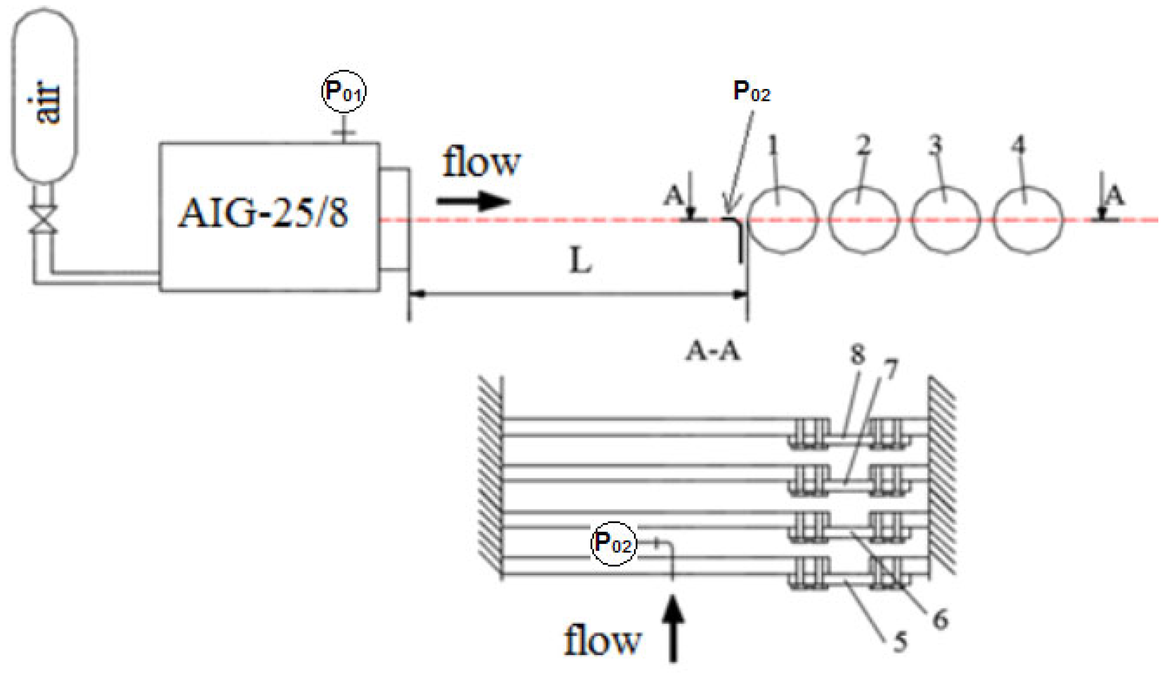
Figure 3 presents the general view of the test bench. The experimental test bench consists of the air impact generator AIG-25/8, the system of heat exchanging tubes (1–4) and strain gauges (5–8).
The air impulse generator AIG-25/8 is purposed to accumulate the energy of compressed air followed by the dramatic exhaust of this air for technological operations such as cleaning of ducts, heat exchangers, and other facilities.
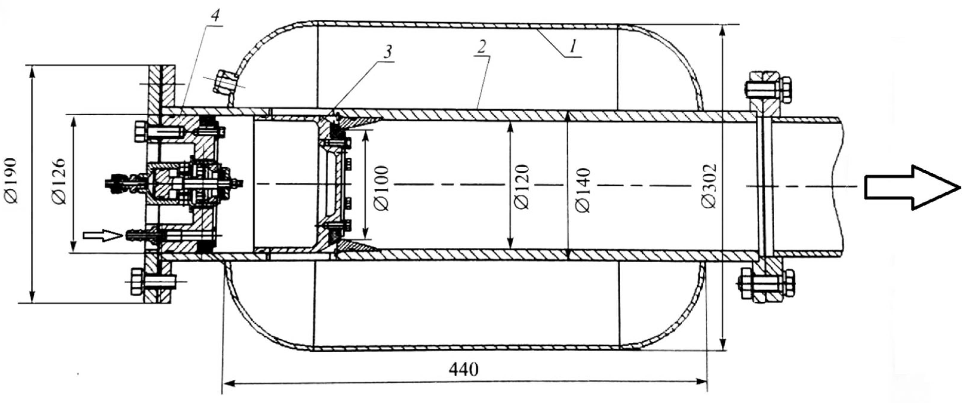
Figure 4 shows the assembly drawing of the air impact generator AIG-25/8. The body (settling chamber) of the air impulse generator 1 is formed by a cylindrical cowl; its purpose is to accumulate a dose of compressed air. Inside the body, there is exhaust nozzle 2 shaped as a cylindrical tube welded to the front and bottom plate. On the external side of the exhaust tube, there is a flange with four holes that are 16 mm in diameter which are used to fix the, air impulse generator on the object. The aft end face of the tube has a flange to fix a closing plug. Here there is also the welded plug to screw in a pressure tap in the settling chamber.
To actuate the air impulse generator, it is necessary to discharge the pressure in the cavity under piston 3 of the closing valve with the aid of the controlled valve 4. Piston 3 moves rightwards, and the dose of compressed air stored in body 1 of the settling chamber is exhausted through exhaust holes in the wall of tube 2 and then through the nozzle; hence the needed shock-wave action is realized. The gas flow rate at the exhaust moment reaches 20 kg/s. After the air exhaust, the process of charge and operation of the air impact generator can be repeated.
Table 1 gives the main engineering characteristics of AIG-25/8.
A set of tubes simulating the tubular heat exchange surfaces of various configurations are installed within a certain distance from the exit of the air impulse generator nozzle perpendicularly to the axis of the formed jet. As it is indicated in [
28], the tubes are made of steel St 20, the tube external diameter is 32 mm. The interaxial distance of the tubes is 75 mm.
The symmetry axis in AIG-25/8 passes through the horizontal plane of tube symmetry (
Figure 5). The exhaust of the air jet from the air impulse generator creates the shock-wave effect on the tubes. The impact force was measured by 8 one-component strain gauges L-XNQ-005 with an accuracy up to 0.03% within the range from 0 to 100 N. The gauges are fixed on tube ends. Two strain gauges permitted determining the impact force in the horizontal and vertical planes.
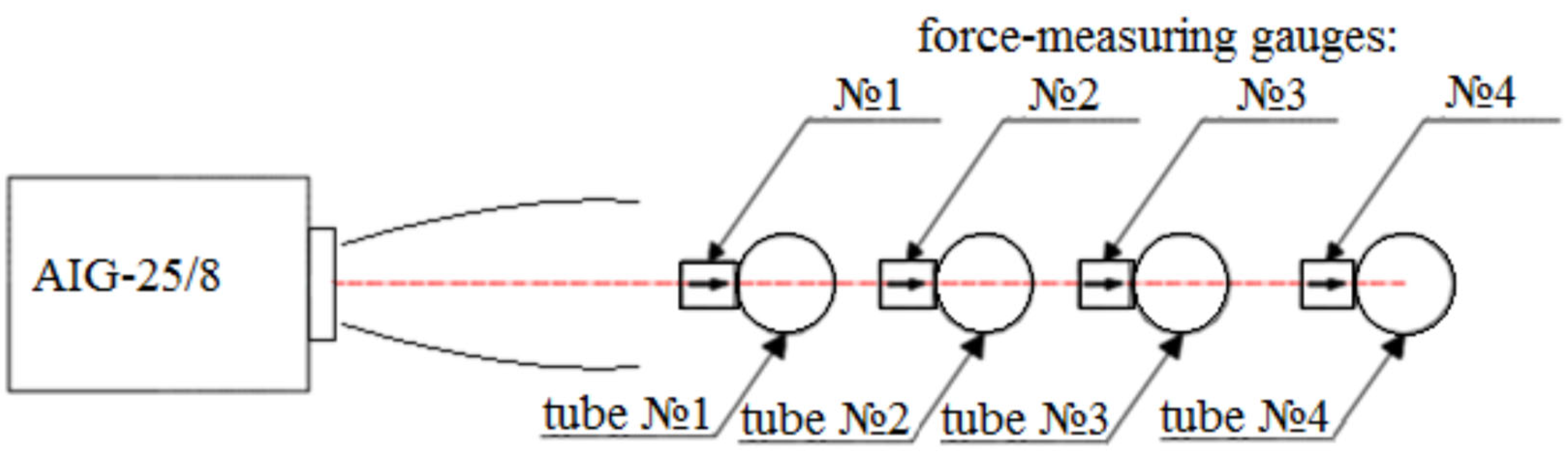
Figure 5 shows the position of force-measuring gauges in the horizontal plane.
DC voltage of 5 V was supplied to feed the strain gauges from a rechargeable battery. The signals of the strain gauges came to a 16-channel AD converter LA-2 USB accurate up to 12 discharges and were registered in the computer memory. Discretization frequency was 10,000 counts per second. Prior to the experiments, the static calibration of each strain gauge was carried out, and the applied loading varied from 0 to 400 N. The scatter of calibration data and gauge linearity did not exceed 1%.
The pressures were measured in the flow with pressure gauges RPD-I, the range of the measured pressure was 0.4 MPa and 1.6 MPa. The accuracy class of the pressure gauges was 0.5%, and feeding voltage of 20 V was supplied to the gauges. The signals of the gauges were measured by a multi-channel AD converter LA-2 USB and registered in the computer memory. Prior to the experiments, the pressure gauges were calibrated with the pressure caliber Elemer-PV-60, the pressure accuracy 0.1%.
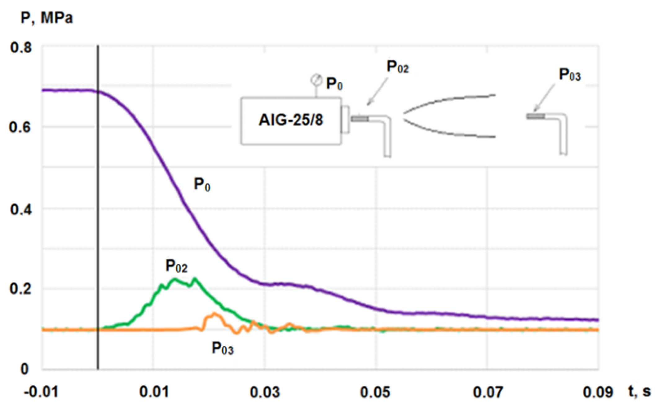
4. Measurement of Non-Stationary Gas Jet Parameters
Figure 6 shows the typical records of experimental pressure values. The pressure in the air impulse generator settling chamber Р
0, the Pitot pressure at the exit nozzle cut Р
02, the Pitot pressure Р
03 by the jet axis within different distances from the nozzle cut were recorded simultaneously. It can be seen from the graph that the jet exposure time is about 0.03 s.
Figure 7 presents the comparison of the pressures P
3 measured within different distances from the nozzle cut. All signals are received in different experiments but they are synchronized by the pitot pressure Р
2 record. We see the delay in the signal of the pitot pressure Р
3 caused by the non-stationary jet developing lengthwise.
Figure 7 also shows the results of pressure calculation for the non-stationary jet obtained in
Section 6. In general, the calculation results are in good agreement with the experimental data.
5. Measurement of the Forces Acting on the Tubular Surfaces
The experiments were carried out for the lengthwise and checkerboard patterns of heat exchange tubes’ position (
Figure 8).
Figure 9 shows the records of the longitudinal force acting on tube No. 1 in three experiments with P
0(0) = 0.7 MPa. Evident that the forces have the express oscillating character caused by the non-stationary nature of the impulse air jet. The maximal value of the impact on the 1st tube in the lengthwise configuration reaches 210 N. In the case of the checkerboard pattern, the acting forces reduce to 100 N.
6. Calculation of the Non-Stationary Axisymmetric Gas Jet
Numerical simulation was carried out in the commercial package ANSYS Fluent 19.0. The Reynolds-averaged Navier-Stokes equations were solved with the k-ω SST turbulence model. The system of equations including the equation of motion, the mass conservation equation, the energy conservation equation, as well as the turbulence model, can be found in ANSYS Fluent theory guide release 19.0 [
29]. Given that the geometry of the nozzle and jet is circular, a 2D axisymmetric formulation was used. The solver was based on density using an implicit equation linearization scheme due to the consideration of viscous flow. Viscosity was determined according to Sutherland. An ideal gas was used as the working fluid. The calculation time step was
t = 0.00001 s.
In the calculation, the total pressure, static atmospheric pressure, and temperature, which were taken as room temperature (T
0 = 295 K), were specified at the inlet boundary. The value of the total pressure changed with a time step in accordance with the experimental data. Preliminarily, the change in the total pressure at the nozzle exit during the jet outflow was experimentally determined. This change in total pressure is shown in
Figure 6 and labeled P
2 in the diagram and graph. The maximal value of the total pressure at the beginning of the calculation was P
02 = 0.24 MPa. Records of the total pressure from the experiment using piecewise linear interpolation were supplemented with the values of change in the magnitude of the total pressure corresponding to a smaller time step than the time step of recording the experimental data. An extended table of the dependence of the total pressure at the nozzle exit at the jet outflow on the time step that corresponds to the calculation time step was loaded as a boundary condition with the command to sequentially change the value of the total pressure from the table at the inlet boundary when changing the time step in the calculation as UDF file. Thus, the calculation was simplified without modeling the flow in the nozzle, with the appropriate assumptions.
The inlet boundary is shifted relative to the rest of the boundary of the computational domain by 10 mm, as shown in the scheme of the computational domain in
Figure 10. The size of the inlet boundary corresponds to the jet exit nozzle cut radius of 60 mm, since the simulation is carried out in an axisymmetric setting. In the direction away from the axis of symmetry, near the inlet boundary, there is a wall boundary condition. This condition is necessary to simulate the outflow of a jet from the channel, and the size of this boundary is 46 mm. Further along the rest of the perimeter of the computational domain, except for the symmetry axis, the boundary was set as an output boundary condition with atmospheric parameters. At the beginning of the calculation,
t = 0 s, the entire calculation area is filled with air with atmospheric parameters. The length of the computational domain was 4000 mm, and the distance from the symmetry axis was 1060 mm.
In the solution region, at the location of the jet core propagation and near the jet core propagation, there was a structured computational grid with the highest density of grid elements. This region of the structured grid extended over the entire length of the computational region and at a distance of 110 mm from the axis of symmetry. The elements of this grid area were identical squares with a size of 1 mm. The rest of the computational domain was filled with an unstructured grid with a growth gradient of 1.2 in the direction of the symmetry axis. This region of the jet propagation solution was not of interest, and the low accuracy of the solution in this region has little effect on the flow in the jet core of interest. The total number of computational grid elements was 500,000. Grid convergence was performed by the total pressure at the nozzle exit. As the grid dimension increased to 500,000 cells, the total pressure reached a constant value.
Figure 11 shows the typical calculation results for the developing non-stationary jet in time and space. In general, the patterns of static pressure distribution coincide with the flow pattern obtained in [
23] (see
Figure 2).
Figure 7 shows that the rate of pressure increase in the non-stationary calculation at different distances from the nozzle exit quite accurately repeats the experimental records, which indicates the correctness of the initial conditions. The calculated graphs obtained for a non-stationary jet, at a different distance from the nozzle exit, lie in the experimental data distribution field and have high coincidence accuracy. As the distance from the nozzle exit increases, the value of the maximum pressure amplitude decreases, since the jet attenuates. The total calculation time interval was limited to 0.0225 s.
Based on the results of non-stationary numerical simulation, it was shown that the simulation technique used makes it possible to simulate the flow of a pulsed jet with high accuracy.
7. Calculation of the Stationary 3D Gas Jet
For the parametric analysis of the forces acting on the heat exchange tubes, it is more advisable to consider the flow around them with the stationary steady flow corresponding to the chosen instant of the working mode.
Stationary calculations of CFD were carried out with the commercial software Flow Simulation which is completely integrated into the system CAD SolidWorks 2018 for solid-state modeling. This computational modulus uses the finite-volume method. In fluid regions, SOLIDWORKS Flow Simulation solves the Navier-Stokes equations, which are formulations of mass, momentum, and energy conservation laws, which can find in [
30].
To close the equation system, SOLIDWORKS Flow Simulation involves the transfer equations for the turbulent kinetic energy and its dissipation velocity using the model k-ε. The intensity of turbulent fluctuations was assumed to be equal to 0.1%, and the turbulence scale was 0.0021 m.
The computational domain is restricted with a symmetry plane perpendicular to the axis of the tube(s). The upper and left boundaries are distanced from the model. The right boundary is the end of the model. On the left boundary, the nozzle cut is modeled; it contains the initial conditions as the Mach number, static pressure, and static temperature. Tube walls were assumed to be adiabatic. At the calculation start, the whole domain was filled with ambient parameters in accordance with the experimental conditions. The size of the computational domain was 0.4 m width * 0.4 m high * 2.5 m long. In the whole computational domain, the mesh was uniform and the total amount of cells was 1.7 million. During the calculation of every 1000 iterations inside the computational domain, cells were split uniformly by the density gradient. The maximum number of cells after adaptation was limited to 2.5 million
Figure 12 demonstrates the typical patterns of the Mach number distribution for the 3D stationary gas jet flowing on a single perpendicular tube. The experimental conditions at the nozzle cut corresponding to the time instant
t = 0.016 s (P
02(0) = 0.235 MPa) are taken as the initial conditions in
Figure 11.
Figure 13 shows the jet with the 10-times increased initial total pressure (P
02(0) = 2.35 MPa). The normal barrel shock wave (the Mach disk) is evident at the high initial pressure in the jet within 0.6 m from the nozzle; after the shock wave, we see the subsonic zone with a dramatic decrease in the total pressure.
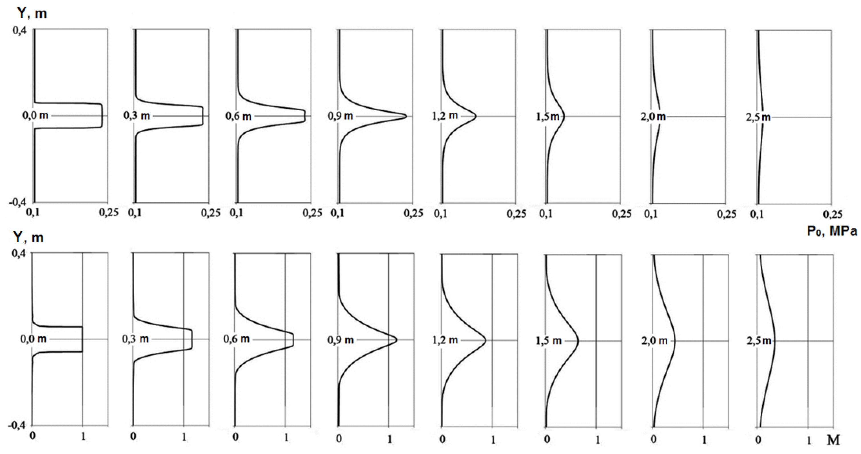
Total pressure and Mach number distribution in the cross sections of the stationary jet within different distances from the nozzle are shown in
Figure 14 and
Figure 15.
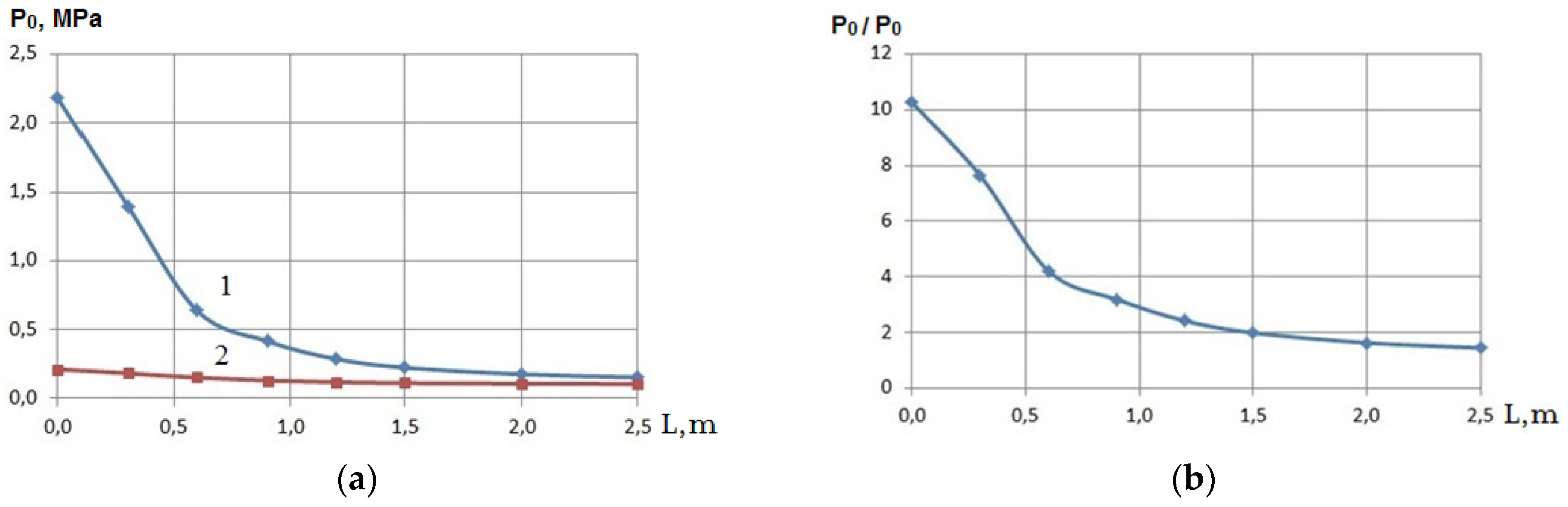
Figure 16 presents the mass-average total pressure in the jet within different distances from the nozzle cut. As the initial pressure rises by 10 times (P
02(0) = 2.35 MPa), the total pressure over the jet length reduces rapidly because of the shock waves, and at 2.5 m it exceeds the total pressure in the jet with the low initial pressure (P
02(0) = 0.235 MPa) only by 1.5 times (see
Figure 16b).
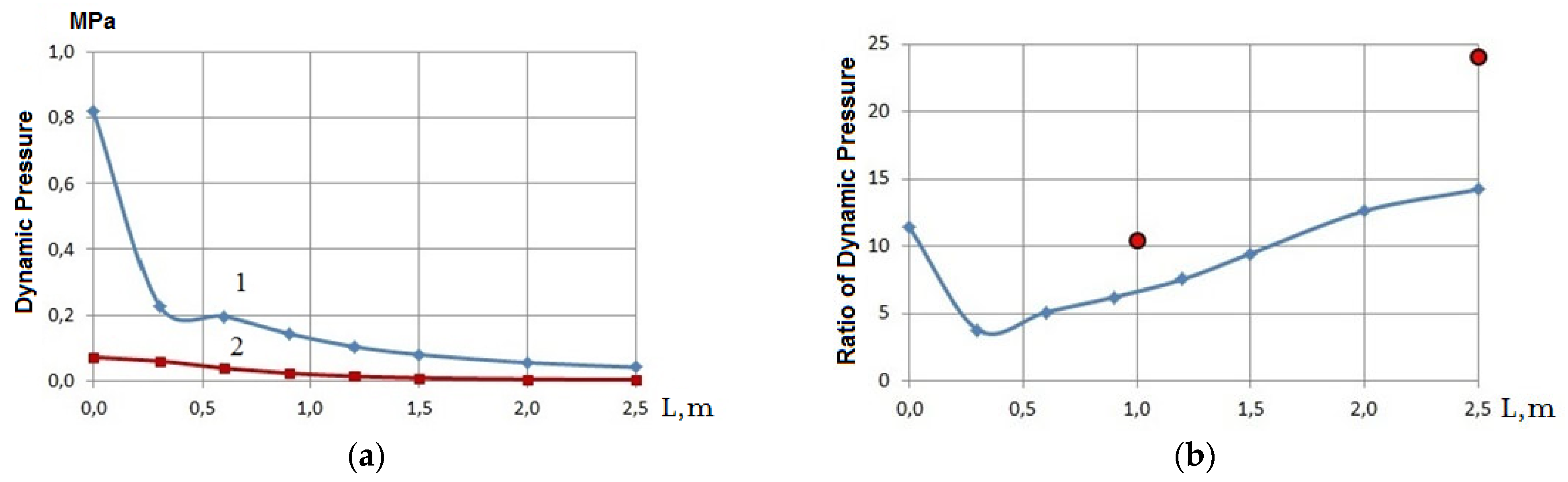
A comparison of the mass-average values of the dynamic pressure (dynamic head) for two jets differing in the initial pressure value (see
Figure 17) shows the unexpected result. At the nozzle cut, the ratio of the dynamic pressures is 11.4 times (the total pressures differ approximately similar), within 0.3–0.6 m the ratio of the dynamic pressures predictably reduces to 4–5, but at the distances above 0.6 m, the ratio of the dynamic pressures start rising, and at 2.5 m, the dynamic pressure of the high-head jet exceeds the pressure of the low-head jet by 14 times (see
Figure 17b). Such a ratio is caused by the rapid drop of the absolute value of the dynamic pressure of the low-head jet within long distances from the nozzle cut.
8. Calculation of the Forces on the Tubular Heat Exchange Surfaces
3D stationary calculations permitted determining the forces acting on the flowed heat exchange tubes and comparing the results with the experimental data.
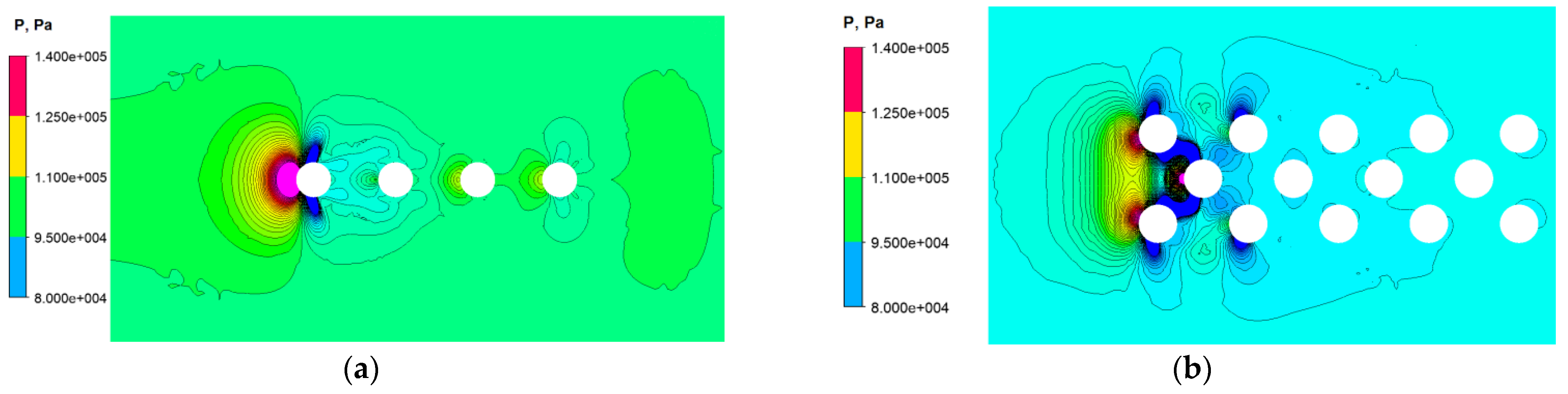
Figure 18 presents the typical examples of the flow.
Table 2 shows the obtained values of the forces.
Evident that the biggest force impacts the first tube in the flow. The second tube is in the bottom area, the force acting on it is essentially lower. Flow re-distribution results in the rise of the forces acting on the next third and fourth tubes which are proven experimentally.
As the distance from the nozzle cut to the heat exchange tubes reduces, the total and dynamic pressures in the jet decrease as is shown in
Figure 16 and
Figure 17, which leads to the reduction of the acting forces. The ratio for the dynamic pressures shown in
Figure 17b permits expecting a similar character of the force change. However, the calculations of the forces acting on the single tube show that the ratio of the forces within 1.0 m is 10.5 (2843 Н and 272 Н), and within 2.5 m, the force ratio increases up to 24 (1881 Н and 78 Н). No proportionality in the acting forces and dynamic pressure means the change in the jet action area on the tube as the initial jet pressure changes. This result stresses again the necessity of application of the numerical modeling to determine the applicability of the specific system of air-impact cleaning for the specific geometry of position of the heat exchange tubes.
9. Conclusions
The calculation and experimental investigations have been carried out to find out the parameters of the impulse air jet for the system of boilers air-impact cleaning. Experiments included the measurement of the pressure distribution in the non-stationary gas jet and the determination of the forces acting on the tubular heat-exchange surfaces. The results of the numerical modeling of the parameters of the impulse non-stationary gas jet are in good agreement with the experimental findings.
It has been demonstrated that the non-stationary impulse air jet forms at the instant opening (opening time 3–5 ms) of the nozzle in the air impulse generator. The gas-dynamic parameters of the formed jet reduce with time because of the limited sizes of the accumulative buffer in the air impulse generator; they also reduce over the space because of the natural dissipation of the air jet energy.
In the conducted experiments and mathematical modeling, the forces acting on heat exchange tubes located at distances from 1.0 m to 2.5 m were determined. Based on the results of mathematical modeling, it was found that as the distance increases, the force acting on a single tube perpendicular to the axis of the created jet decreases from 272 N to 78 N. Similar results were obtained experimentally. By numerical simulation, it was found that as the jet pressure rises by 10 times, the respective values rise to 2843 N (by 10 times) and 1881 N (by 24 times). Thus, an increase of the pressure in the created impulse jet permits increasing essentially the forces acting (by 24 times) within long distances from the exit nozzle.
The lack of proportionality between the increase in the force of impact on the surface and the increase in dynamic pressure means a change in the area of jet impact. This effect makes it possible to more effectively apply the air impact cleaning system in this configuration. The results obtained can be used in the development of specific systems for the air impact cleaning system of boiler units with other sizes and configurations of the heat exchange tubes.


