Abstract
The slagging of heating surfaces by fly ash significantly complicates the long term operation of solid-fuel boilers. Gas pulse technologies offer a potentially convenient, inexpensive, yet efficient way for online slag deposits removal. The creation and application of real boiler cleaning systems using gas pulse technologies is a relatively new direction in the energy sector and requires scientific research on various aspects. In this work, the numerical investigation of the gas-dynamic flow arising when the package of heat-exchange tubes is blown with single air jet created by a pneumopulse cleaning system has been carried out. The forces acting on the heat-exchange tubes located at distances 1.0 m and 2.0 m from the exhaust nozzle with various configurations of tubes in the package have been determined. It is shown that an increase in the pressure of the generated air jet makes it possible to significantly increase the acting forces at large distances from the exhaust nozzle. The results of this study and similar calculations for real geometry will increase the validity of engineering solutions used in the development of pneumopulse cleaning systems for large power boilers.
1. Introduction
The operation of power plant boilers based on the combustion of solid fossil fuels, hard coal in particular, is accompanied by the production of a huge amount of ash, which represents the non-combustible mineral part of the fuel used. The main part of ash falls down to the bottom of the boiler’s combustion chamber and is called bottom ash. Fine particles of burned fuel that are driven out together with the flue gases are called fly ash (flue ash, coal ash, or pulverized fuel ash). In the scientific literature, the problem of utilization of the resulting bottom ash as the largest hard waste stream is considered first of all. The next problem is fly ash filtration from the flue gases that are emitted into the atmosphere [].
However, there is another problem associated with fly ash, which significantly complicates the operation of solid-fuel boilers []. At high temperatures, fly ash particles become molten or softened. Some of the particles collide with the tubes of the screens or heating surfaces and stick to them, accumulating in large quantities. The process of slagging of heating surfaces begins. Slagging is a process of intense sticking of ash particles, which are in a molten or softened state, on the surface of heat exchange tubes. Although there are many types of ash deposits, the most common deposits can be categorized into two major groups: high-temperature deposits and the low-temperature deposits. These deposits form under very different temperatures and from different ash materials. In high-temperature fouling, the bonding of particles is due to silicate liquid phases. High temperature fouling occurs in regions of the boiler where temperatures exceed the stability of the sulfate-bearing phases (~1200 K). The higher temperature causes melting and interaction of the particles in the liquid phase. Once a liquid phase has formed on the outside of the deposit, it becomes an efficient collector of ash particles, regardless of the individual melting characteristics of the particles. Low-temperature ash deposition occurs at temperatures of ~800 K. In low-temperature fouling, the bonding is a result of the formation of sulfates, principally CaSO4. Low-temperature deposits form when small calcium oxide particles in a deposit undergo sulfation through reaction with sulfur dioxide in the gas stream. This reaction produces calcium sulfate, which causes particle-to-particle bonding and fills in the available pore space in the deposits. This pore filling produces very strong, brick-like deposits that are difficult to remove. The resulting significant growths of ash from time to time exfoliate from the tubes and fall down into the lower part of the combustion chamber. When falling down slag grows, deformation or even destruction of the heat exchange system of the boiler, as well as slag removal devices, is possible.
The convective heating surfaces, which look like the packages of heat exchange tubes located at the outlet of the boiler, are also subject to slagging. Particles in the solid state can also settle on the tubes, polluting their outer surface, both from the frontal and from the back sides. These contaminants can form loose or hard-to-remove deposits. Deposits on tube surfaces reduce the heat transfer coefficient (deposits have low thermal conductivity and are a kind of thermal insulation) and the efficiency of heat transfer. As a result, the temperature of the flue gases increases. The growth of slag deposits leads to clogging of the passages between the tubes and to partial or complete blocking of the cross section for the passage of gases. Partial overlap leads to an increase in the resistance of the gas-dynamic path of the boiler and requires an increase in the power of smoke exhausters. If the power of the smoke exhausters is insufficient to remove the combustion products from the slagged boiler, then it is necessary to reduce its productivity.
Deslagging of the furnace bottom and cleaning of heating surfaces is a long and laborious process that requires shutting down the boiler and attracting significant human and material resources. On stopped boilers, mainly mechanical methods of cleaning using manual labor are used. It is evident that slagging reduces the efficiency of the boiler and increases the operating costs due to periodic stops for deslagging. Therefore, high-power boilers burning solid or liquid fuels must always be equipped with surface cleaning systems. There are various methods for cleaning heating surfaces; however, there are still no reliable and effective means of cleaning heating surfaces from ash deposits.
As the review of the literature shows, the main direction in the development of cleaning systems is the use of short-term gas pulse methods of influencing the surfaces to be cleaned using powerful gas jets. In particular, at the end of the last century, a large amount of theoretical and experimental research was carried out in the field of cleaning by detonation wave pulse [,,,,,]. The main element of the detonation gas-pulse cleaning system is an explosion chamber with a volume of up to 1 m3, which is preliminarily filled with a mixture of combustible gas (hydrogen, propane, methane) with air. After filling the chamber, the mixture is ignited and a jet of detonation combustion products with a pressure of 0.6–0.8 MPa through a pipeline with a diameter of 100–200 mm is fed to a given area of the boiler and acts here on the heat exchange surfaces. This method has a number of disadvantages (complexity, explosion hazard, large dimensions, etc.), which limits its scope.
More promising and versatile is the method of pneumopulse cleaning. In this case, a pulsed air jet is formed using a pneumopulse generator []. A typical installation diagram of a pneumopulse generator for cleaning a tubular heat exchanger is shown in Figure 1. Compressed air with a pressure of 0.8–1.0 MPa is preliminarily accumulated in the accumulative cavity of the pneumogenerator with a volume of 0.02–0.05 m3. At a given moment in time, a quick-acting shutter opens and compressed air is ejected through an exhaust pipe with a diameter of 100–150 mm, affecting the heat exchange surfaces being cleaned.
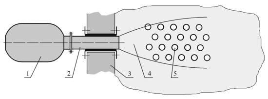
Figure 1.
A typical installation diagram of a pneumopulse generator for cleaning a tubular heat exchanger. 1—pneumopulse generator; 2—exhaust pipe; 3—boiler wall; 4—pulsed gas jet; 5—heat exchange tubes.
Pneumopulse cleaning systems are characterized by safe operation and a wide range of regulation of the generated force impact. The accumulated experience [,,,,,,,,,,,] has shown that pneumopulse systems for cleaning high-power boilers should have the following technological characteristics:
- -
- Sufficiently high power of the exhaust jet (250 kJ and more);
- -
- Low working air pressure (1–2 MPa);
- -
- High reliability and ease of maintenance of valve devices;
- -
- Protection of moving elements of the system from aggressive flue gases from the boiler;
- -
- Low cost of manufacturing and installation of the system;
- -
- Technical simplicity of actuating devices;
- -
- Low material consumption and low power consumption;
- -
- Ease of management and automation capability.
The development of a pneumopulse cleaning system is based first of all on an analysis of the rate of formation and strength of the expected deposits, depending on the temperature regimes of the boiler and its individual elements. Taking into account the geometric and design features of a real boiler unit, the configuration of the cleaning system, the number and location of pneumatic generators, auxiliary elements (pipelines, service platforms, air and cable routes, etc.) are determined. It is known that the strength of deposits increases rapidly during the first 6 h of boiler operation [,,,,]. Therefore, to ensure high-quality cleaning of technological objects, the most rational is the preventive cleaning mode. It means that the frequency of switching period of the pneumopulse cleaning system must be 1–2 h under the control of a fully automated control and monitoring system.
The first works on the use of pneumopulse cleaning of heating surfaces of boiler units were carried out in UralVTI []. Systematic studies of the possibilities of using pneumopulse devices for cleaning boiler units have been started since 1992 at the Institute of Theoretical and Applied Mechanics of the Siberian Branch of the Russian Academy of Sciences (Novosibirsk) in the following main areas []:
- -
- Development of principles for designing pulsed gas jet generators;
- -
- Study of the dynamics of formation and propagation of shock waves and non-stationary gas jets;
- -
- Development of real technological processes using pulsed gas jets.
As a result of these studies, a number of pneumopulse cleaning systems for boiler units of low and high power were created [,,,,,]. The experience of operating pneumopulse systems for cleaning boiler units was reported at all-Russian and international conferences [,,,] and aroused great interest among energy industry specialists.
In the process of creating and testing various systems for pneumopulse cleaning, the main technical issues related to the design of pneumogenerators, their placement, automated control, etc., were solved. At present, the issues of evaluating the effectiveness of the impact of the generated gas jets on the cleaned surfaces, which depend on the gas dynamics of a complex three-dimensional flow around heat exchange tubes, are of particular relevance.
The paper [] presents the results of a feasibility study of detonation gas-pulse technology for removing slag and fouling deposits in coal-fired utility power plant boilers. Computational Fluid Dynamics (CFD) simulations of non-stationary gas-dynamic flow during the passage of a shock wave through a package of three transverse tubes were performed. The results provide visual and quantitative data to study the potential mechanisms for removal of slag. The possibility of slag removal on the back sides of the tube attributed to velocity scrubbing, wave reflection, negative velocity impact and potentially wave reverberations within tubes package was found. A significant limitation of the results’ applicability is that the numerical simulations were carried out at small distances from the exit of the detonation tube to the heat exchange tubes, while usually the shock wave with an increasing distance practically disappears.
In the present work, the numerical investigation of the impact forces of a gas jet on heat exchange tubes of various configurations in the packages located at a sufficiently large distance from the exhaust nozzle is exhibited. The work is part of research on the creation of a methodology for assessing the effectiveness of pulse gas jets for the cleaning of ash deposits on tubular heat exchangers of boiler units, which is based on the calculated and experimental determination of the gas-dynamic parameters of pulsed gas jets and their force impact on tube packages of various configurations. The results of this study will increase the validity of engineering solutions used in the development of pneumopulse cleaning systems for high-power boilers.
2. Calculation of Stationary Gas Jets
Stationary CFD calculations were performed using the commercial Flow Simulation software, which is fully integrated into the SolidWorks CAD system for solid modeling. The specified computing module uses the finite volume method. Calculations of a stationary symmetric turbulent flow were carried out on the basis of the Reynolds-averaged Navier–Stokes (RANS) equations and the k-ε turbulence model. To close the system of equations, the Flow Simulation program uses the transfer equations for turbulent kinetic energy and its dissipation rate. The intensity of turbulent fluctuations was taken equal to 0.1%, and the scale of turbulence was 0.0021 m. The computational domains are shown in Figure 2.
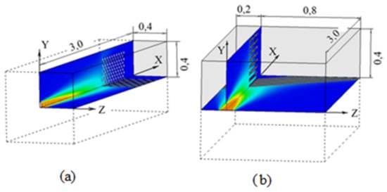
Figure 2.
Computational domains. (a) Blowing at an angle of α = 90°; and (b) blowing at an angle of α = 45°. Dimensions in m.
The nozzle exit is located on the left boundary, on which the initial conditions are set in the form of the Mach number, static pressure, and static temperature. In the case of a jet impingement at an angle of α = 90°, a quarter of the flow pattern relative to the planes of symmetry was modeled. The size of the computational domain in this case was X × Y × Z = 3.0 m × 0.4 m × 0.4 m.
In the case of a jet impingement at an angle of α = 45°, the left part of the flow pattern (Z = −0.2 m) was also partially calculated, in which one could expect the force effect of the oncoming jet. The size of the computational domain in this case was X × Y × Z = 3.0 m × 0.4 m × 1.0 m.
In the entire computational domain, the grid was close to homogeneous, and the total number of cells was 1.7–2.5 million. The tube walls were assumed to be adiabatic. At the beginning of the calculation, the entire area was filled with environmental parameters in accordance with the experimental conditions. Inside the computational domain, the cells were uniformly subdivided along the density gradient. The adopted calculation technique was tested by comparison with experimental results, which is described in detail in [].
3. Calculation Results
We consider a stationary air jet flowing from an axisymmetric sonic nozzle with a diameter of D = 115 mm onto a package of tubes located at a given distance from the nozzle exit. The main task of the calculations was to determine the aerodynamic forces acting on various tubes in the package.
The following parameters were varied in the calculations: the total pressure of the generated pulsed jet (P0 = 0.235 MPa and 2.35 MPa), the distance from the nozzle exit to the plane of the first tubes in the package along the jet axis X (L = 1 m and 2 m), the angle of inclination of the jet axis to the planes of the first tube α (90° and 45°), as well as the configuration of the tubes in the package (distributed arrangement (chess) or in-line arrangement (corridor) (see Figure 3).
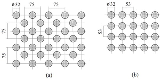
Figure 3.
Configuration of the tubes in the package. (a)—chess arrangement; (b)—corridor arrangement. Dimensions in mm.
The numbering and description of the calculation options are given in Table 1. Here, a number of tubes affected by air jet and total force on these tubes in each calculated case is pointed.

Table 1.
Calculation cases for determination of the forces acting on heat exchange tubes.
Typical flow patterns when flowing around a package with distributed tubes (chess arrangement) are shown in Figure 4, Figure 5, Figure 6 and Figure 7. Here, on the cross section of the tube bundles, the area of influence of the incoming air jet is contoured by a line, where the tubes are affected by distinguishable values of aerodynamic forces.
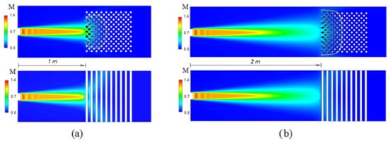
Figure 4.
Blowing of the tube package by an air jet with pressure P0 = 0.235 MPa. (a) Case 1; and (b) case 5. Upper—XOY plane, lower—XOZ plane.
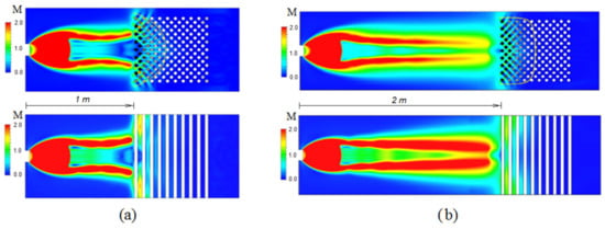
Figure 5.
Blowing of the tube package with an air jet with a pressure of P0 = 2.35 MPa. (a) Case 9; and (b) case 13. Upper—XOY plane, lower—XOZ plane.
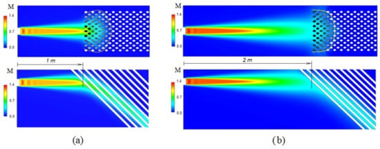
Figure 6.
Blowing of the tube package by an air jet with pressure P0 = 0.235 MPa. (a) Case 3; and (b) case 7. Upper—XOY plane, lower—XOZ plane.
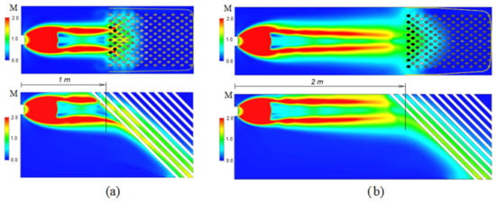
Figure 7.
Blowing of the tube package by an air jet with a pressure of P0 = 2.35 MPa. (a) Case 11; and (b) case 15. Upper—XOY plane, lower—XOZ plane.
Typical flow patterns when flowing around with in-line tubes (corridor arrangement) are shown in Figure 8, Figure 9, Figure 10 and Figure 11. Here, on the cross section of the tube bundles, the area of influence of the incoming air jet is contoured by a line, where the tubes are affected by distinguishable values of aerodynamic forces.
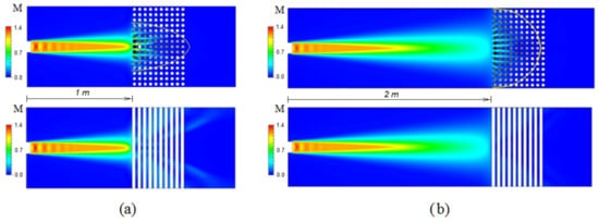
Figure 8.
Blowing of the tube package by an air jet with pressure P0 = 0.235 MPa. (a) Case 2; and (b) case 6. Upper—XOY plane, lower—XOZ plane.
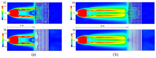
Figure 9.
Blowing of the tube package by an air jet with a pressure of P0 = 2.35 MPa. (a) Case 10; and (b) case 14. Upper—XOY plane, lower—XOZ plane.
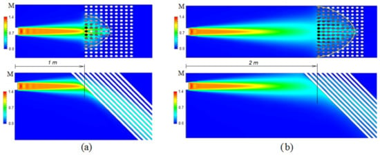
Figure 10.
Blowing of the tube package by an air jet with pressure P0 = 0.235 MPa. (a) Case 4; and (b) case 8. Upper—XOY plane, lower—XOZ plane.
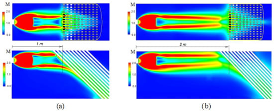
Figure 11.
Blowing of the tube package by an air jet with pressure P0 = 2.35 MPa. (a) Case 12; and (b) case 16. Upper—XOY plane, lower—XOZ plane.
According to calculation results, Table 1 shows the number of tubes on which the effective force exceeds 1% of the total jet force RC = P0 × FC. Here, P0 is the total pressure at the nozzle exit (P0 = 0.235 MPa and 2.35 MPa), and FC is the nozzle exit area (FC = 0.0104 m2). It also shows the values of the total force RΣ acting on all tubes in the package. The same results are shown in Figure 12.
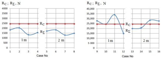
Figure 12.
Total forces in various calculated cases (see Table 1).
It can be seen from Table 1 and Figure 12 that at a total pressure at the nozzle exit P0 = 0.235 MPa (Cases 1–8), the total force RΣ acting on the tubes in package ranges from 1316 N to 2024 N (54% to 84% from the total jet force RC). The number of effectively blown tubes in a package at the distance 1 m constitutes 29% at chess arrangement (case 1) and 47% at corridor arrangement (case 2). Inclination of the jet flow 45° gives us 38% at chess arrangement (case 3) and 25% at corridor arrangement (case 4) because chess arrangement is turning into corridor arrangement and vice versa. At the distance of 2 m, the number of effectively blown tubes in a package constitutes 42% at chess arrangement (case 5) and 72% at corridor arrangement (case 6). This is explained by increasing of affected area. Inclination of the jet flow 45° at this distance gives us a decrease of affected tubes to 31% at chess arrangement (case 7) and 57% at corridor arrangement (case 8).
With an increase in the total pressure of the jet by a factor of 10 (2.35 MPa), the total forces RΣ acting on the cleaned tubes increase significantly and reach up to 33,968 N (140% of the total jet force RC). The number of effectively blown tubes in a package at the distance 1 m constitutes 35% at chess arrangement (case 9) and 88% at corridor arrangement (case 10). At the distance of 2 m, the number of effectively blown tubes in a package constitutes 46% at chess arrangement (case 13) and 45% at corridor arrangement (case 14). Inclination of the jet flow up to 45° gives us 100% of effectively blown tubes at both distances (cases 11, 12, 15, 16).
The results of this study show a complex relationship between the aerodynamic pattern of the flow around, as well as the force impact on the tubes, with a change of the distance, initial pressure and tubes arrangement in the package. It means the necessity of numerical simulation to determine the possibility of using a specific pneumopulse cleaning system for a specific geometry of the heat exchange tubes, and similar calculations for real geometry will increase the validity of engineering solutions used in the development of pneumopulse cleaning systems for large power boilers.
4. Conclusions
The slagging of heating surfaces by fly ash significantly complicates the long-term operation of solid-fuel boilers. Gas pulse technologies offer a potentially convenient, inexpensive, yet efficient way for online slag deposits removal. Different aspects of these technologies are now under consideration. In this work, the numerical investigation of the gas-dynamic flow arising when the package of heat-exchange tubes is blown with single air jet created by pneumopulse cleaning system is performed.
Stationary distribution of flow parameters around heat-exchange tubes for real conditions in the typical boiler were obtained: the diameter of the exhaust nozzle is 100 mm, the air pressure is 0.235 MPa and 2.35 MPa, the distance from the nozzle exit to the first tubes in a package is 1 and 2 m, the distance between the tubes is 53 and 75 mm, the total amount of tubes in a package is 150 and 162 pieces.
The forces acting on the heat exchange tubes located at distances from 1.0 m to 2.0 m were determined for various configurations of tubes in a package. It is shown that in the considered variants of blowing, the total force acting on the tubes is from 53% to 140% of the total force of the jet flowing from the nozzle. In this case, from 37 to 162 tubes receive a force effect exceeding 1% of the total impulse (i.e., more than 240 N at an outflowing jet pressure of 0.235 MPa and more than 2400 N at a pressure of 2.35 MPa). It is shown that an increase in the pressure of the generated air jet makes it possible to significantly increase the acting forces at large distances from the exhaust nozzle.
The estimates obtained show the distribution and magnitude of the acting aerodynamic forces from the air jet on various heat exchange tubes in the package for real boiler conditions. To resolve the issue of the effectiveness of the pneumopulse cleaning system, these aerodynamic forces must be compared with the expected strength of the ash deposits. However, the strength of ash deposits depends on a large number of initial factors, primarily on the time of their formation, and it has an uncertain value. Therefore, such a comparison is not made in this work.
Similar calculations can be made for other heat exchange tube configurations. These results will increase the validity of engineering solutions used in the development of pneumopulse cleaning systems for large power boilers.
Funding
This work was financially supported by the Ministry of Science and Higher Education of the Russian Federation under state contract N13.1902.21.0014 (agreement N075-15-2020-806).
Institutional Review Board Statement
Not applicable.
Informed Consent Statement
Not applicable.
Data Availability Statement
Data will be provided upon request.
Conflicts of Interest
The author declares no conflict of interest.
Nomenclature
| P0 | Total pressure: Pa |
| L | Distance, m |
| M | Mach number |
| D | Nozzle diameter, m |
| FC | Nozzle area, m2 |
| X | Longitudinal coordinate |
| Y | Vertical coordinate |
| Z | Transverse coordinate |
| RC | Total jet force, N |
| RΣ | Acting force, N |
| α | Jet inclination, degree |
References
- Alekhnovich, A.N. Topical issues in the study of slagging properties of coals and slagging of boilers. In Proceedings of the V Scientific-Practical Conference “The Mineral Part of the Fuel, Slagging, Cleaning of Boilers, Trapping and Use of Ash”, UralVTI, Chelyabinsk, Russia, 7–8 June 2011; Volume I, pp. 1–9. (In Russian). [Google Scholar]
- Podymov, V.N.; Gabidovsky, A.G. On the Mechanism of Impulse Cleaning; Kazan State University: Kazan, Russia, 1979; p. 79. (In Russian) [Google Scholar]
- Shchelokov, Y.M.; Avvakumov, A.M.; Sazykin, Y.K. Cleaning of Heating Surfaces of Waste Heat Boilers; Energoatomizdat: Moscow, Russia, 1984; p. 160. (In Russian) [Google Scholar]
- Bulatov, N.Y.; Sharygin, M.P.; Moldabekov, S.M.; Bikbau, M.Y. Impulse Aerodynamic Cleaning of Surfaces in Chemical Technology; Gylym: Alma-Ata, Russia, 1990. (In Russian) [Google Scholar]
- Guidelines for the Calculation, Design and Operation of Impulse Cleaning Devices; MU 34-70-145-86; Soyuztekhenergo: Moscow, Russia, 1987. (In Russian)
- Hanjalic, K.; Smajevic, I. Detonation-Wave Technique for On-Load Deposit Removal from Surfaces Exposed to Fouling: Part II—Full-Scale Application. Trans. ASME J. Eng. Gas Turbines Power 1994, 116, 231–236. [Google Scholar] [CrossRef]
- Pogrebnyak, A.P.; Kokorev, V.L.; Kokorev, A.L.; Moiseenko, I.O. The results of the development of automated systems for gas-pulse cleaning (GIP) designed by TsKTI on boilers for industrial and municipal energy. In Proceedings of the V Scientific-Practical Conference “The Mineral Part of the Fuel, Slagging, Cleaning of Boilers, Trapping and Use of Ash”, Chelyabinsk, Russia, 7–9 June 2011; pp. 8–13. (In Russian). [Google Scholar]
- Zvegintsev, V.I. Pneumopulse Generator for Surface Cleaning. Patent RF No. 2023228, 7 August 1992. [Google Scholar]
- Lyskov, V.Y.; Alekhnovich, A.N.; Kochetov, V.A.; Fursov, V.G.; Guzenko, S.I. Air-impact facility for cleaning of boiler heated surfaces. Energetik 1979, 4, 21–22. (In Russian) [Google Scholar]
- Zvegintsev, V.I. Gas-Dynamic Installations of Short Duration. Part 2. Installations for Industrial Applications; Parallel: Novosibirsk, Russia, 2015; p. 339. [Google Scholar]
- Zvegintsev, V.I.; Chirkashenko, V.F.; Kharchenko, V.V.; Serant, F.A. Pneumopulse systems for cleaning the convective shaft of the P-67 boiler. Electr. Stn. 2003, 7, 19–22. (In Russian) [Google Scholar]
- Zvegintsev, V.I.; Shabanov, I.I. Experience in creating pneumopulse systems for cleaning convective heating surfaces of boiler units. Energetik 2009, 1, 21–24. (In Russian) [Google Scholar]
- Zuber, A. Experience in the use of pneumopulse cleaning systems in Poland. In Proceedings of the V Scientific-Practical Conference “The Mineral Part of the Fuel, Slagging, Cleaning of Boilers, Trapping and Use of Ash”, UralVTI, Chelyabinsk, Russia, 7–9 June 2011; Volume II, pp. 45–56. [Google Scholar]
- Zvegintsev, V.I. Principles of designing pneumopulse cleaning systems for high power boiler units. Energetik 2013, 9, 49–53. (In Russian) [Google Scholar]
- Agliulin, S.G.; Nikolaev, S.F.; Zvegintsev, V.I.; Yurkin, I.A.; Shabanov, I.I.; Palkin, V.F.; Sergienko, S.P.; Vlasov, S.M. Investigation of the efficiency of pneumopulse cleaning of screen surfaces of the PK-38 boiler at Nazarovskaya TPP. Therm. Power Eng. 2014, 9, 1–8. (In Russian) [Google Scholar]
- Zvegintsev, V.I. Pneumopulse cleaning of heating systems. Energetik 2020, 6, 35–40. (In Russian) [Google Scholar] [CrossRef]
- Zvegintsev, V.I. Principles of designing pneumopulse cleaning systems for high power boiler units. In Proceedings of the V Scientific-Practical Conference “The Mineral Part of the Fuel, Slagging, Cleaning of Boilers, Trapping and Use of Ash”, UralVTI, Chelyabinsk, Russia, 7–9 June 2011; Volume II, pp. 14–26. (In Russian). [Google Scholar]
- Shabanov, I.I. Problems of implementation of pneumopulse systems for cleaning convective surfaces of boiler units. In Proceeding of the V Scientific-Practical Conference “The Mineral Part of the Fuel, Slagging, Cleaning of Boilers, Trapping and Use of Ash”, UralVTI, Chelyabinsk, Russia, 7–9 June 2011; Volume II, pp. 27–33. (In Russian). [Google Scholar]
- Nikolaev, S.F. Experience in the use of a pneumopulse cleaning system at the PK-38 boiler at the Nazarovskaya State District Power Plant. In Proceedings of the V Scientific-Practical Conference “The Mineral Part of the Fuel, Slagging, Cleaning of Boilers, Trapping and Use of Ash”, UralVTI, Chelyabinsk, Russia, 7–9 June 2011; Volume III, pp. 34–44. (In Russian). [Google Scholar]
- Zvegintsev, V.I. Pneumopulse Technology for Industrial Applications. J. Int. Sci. Publ. Mater. Methods Technol. 2012, 6, 242–271. [Google Scholar]
- Menshikov, K.S. Impact of Pulsed Air Jets on the Surface of Convective Heat Transfer of a Boiler Unit. High-Energy Processes in Condensed Matter (HEPCM 2020). AIP Conf. Proc. 2020, 2288, 030027. [Google Scholar] [CrossRef]
- Huque, Z.; Ali, M.R.; Kommalapati, R. Application of pulse detonation technology for boiler slag removal. Fuel Process. Technol. 2009, 90, 558–569. [Google Scholar] [CrossRef]
- Zvegintsev, V.I.; Menshikov, K.S. Study of the effectiveness of a pneumopulse system for cleaning of the convective heat exchange surfaces in boiler units. Energetik 2021, 12, 22–28. (In Russian) [Google Scholar]
Publisher’s Note: MDPI stays neutral with regard to jurisdictional claims in published maps and institutional affiliations. |
© 2022 by the author. Licensee MDPI, Basel, Switzerland. This article is an open access article distributed under the terms and conditions of the Creative Commons Attribution (CC BY) license (https://creativecommons.org/licenses/by/4.0/).