Article

An Investigation into the Flow of Rotating Orifices with Euler Angle and the Calculation Model of Discharge Coefficient Considering the Effect of Comprehensive Incidence Angle

1
School of Energy and Power Engineering, Beihang University, XueYuan Road No. 37, HaiDian District, Beijing 100191, China
2
Research Institute Pof Aero-Engine, Beihang University, XueYuan Road No. 37, HaiDian District, Beijing 100191, China
*
Author to whom correspondence should be addressed.
Aerospace 2022, 9(4), 179; https://doi.org/10.3390/aerospace9040179
Submission received: 23 February 2022 / Revised: 17 March 2022 / Accepted: 17 March 2022 / Published: 24 March 2022

Abstract

:
As a typical flow element in an aero-engines, orifices play a vital role in the distribution and control of the mass flow rate within the secondary air system. In particular, rotating orifices with complex geometry (Euler angles) may significantly vary the discharge coefficients. Understanding the discharge coefficients of these orifices may guarantee a more reasonable distribution of the internal flow within the air system. This contributes to the safety, reliability, and structural integrity of the aero-engine under the all-inclusive line. In this paper, the flow state within the orifice and the discharge coefficient have been studied under the condition of different Euler angles ( α 0 = 0 30 ° and β 0 = 0 30 ° ) and rotational speeds (0–10,000 r/min). The comprehensive incidence angle is proposed to describe the combined effect of Euler angles and rotation. The correlation between the discharge coefficient and the comprehensive incidence angle is also given. At the same time, a general calculation model of the orifices is established considering the effect of the comprehensive incidence angle. The results indicate that the effects of the circumferential inclination angle, radial inclination angle, and rotation may be more clearly expressed by the comprehensive incidence angle. The larger discharge coefficient is obtained when the comprehensive incidence angle is close to 0, and under the fixed rotational speed and flow condition, the maximum discharge coefficient can be obtained by arranging the appropriate Euler angle for the orifice. Compared with the experimental results in the published literature, the calculation results of the model have an overall error of less than 6%. The calculation accuracy is high enough for the one-dimensional simulation of the secondary air system.

1. Introduction

As an important subsystem of an aero-engine, the secondary air system has taken on more functions, such as cooling, sealing, and axial force control, which affects the safety, reliability, and structural integrity of the aero-engine under the all-inclusive line [1]. In recent years, with continuous improvements such as a high thrust-to-weight ratio, high acceleration, high economy, and other performance indicators for aero-engines, there has also been an increase in difficulty in the design of secondary air systems. Although high-strength composite materials have been widely used in modern aviation structures [2], the need to meet the strength requirements of the material and the various functional requirements of the secondary air system using an airflow rate that is as low as possible is another focus of current research. It is necessary to have a more accurate understanding of the discharge coefficient for the flow elements inside the secondary air system.
Orifices are the most commonly used throttling elements in the air system [3]. The flow characteristics of the orifice are influenced by various factors, which have a direct impact on the functions of the secondary air system. Thus, it is of great importance to accurately master the flow characteristics of orifices for the refined design of the secondary air system.
Previous research has shown that the main factors affecting the orifice discharge coefficient can be divided into two groups: geometric structure and flow parameters [4].
Geometric structure:
  • The length to diameter ratio of the orifice (l/d);
  • Radiusing or chamfering of the orifice;
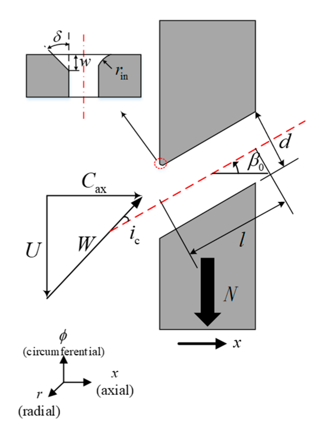
  • Euler angles of the orifice (radial inclination angles α 0   and circumferential inclination angles β 0 ).
Flow parameters:
  • The Reynolds number of the flow inside the orifice (Re);
  • The pressure ratio across the orifice ( π );
  • The internal and external cross-flow of the orifice;
  • Pre-swirl of the inlet;
  • Rotation.
The early studies on the discharge coefficient were mainly focused on static orifices. Thus far, researchers have carried out a large number of experimental studies for the above-mentioned factors, and several discharge coefficient correlations are proposed in the literature [5,6,7,8,9]. However, aero-engines, as a high-speed rotating machine, contain not only static orifices inside, but also a large number of rotating orifices on shafts, rotating discs, and drums, etc. The effect of rotation on the discharge coefficient of the orifice cannot be ignored, which has drawn more attention from many scholars recently.
The effect of rotation on the discharge coefficient of the orifice was first studied as early as 1965. Meyfarth et al. [10] presented the discharge coefficient of rotating axial orifices in terms of the circumferential velocity parameter for the first time, which is the ratio of the circumferential velocity of the orifice and the axial velocity of the flow into the orifice. The final results indicated that the discharge coefficient begins to decrease when the circumferential velocity parameter is greater than 0.5. The combined effects of pressure ratio, length-to-diameter ratio, and rotational speed (N = 0–10,000 r/min) on the discharge coefficient of rotating axial orifices were systematically investigated by Wittig et al. [11] and Maeng et al. [12] in 1994 by experiments and numerical simulation. The velocity ratio ( U / C ax ) in the absolute coordinate system was still used to describe the effect of rotation. It was found that an inclination angle caused by rotation resulted in a fluid separation at the inlet of the orifice, which reduces the discharge coefficient of orifices. The effects of the inlet radius and chamfering on the rotating orifices are of great importance as well. Zimmermann et al. [13] introduced a method for processing the discharge coefficient of the rotating orifices in a relative coordinate system, which solved the problems wherein the discharge coefficient exceeds the unit and the circumferential velocity ratio tends to infinity in the absolute coordinate system. On this basis, Dittmann et al. [14] investigated the effect of the inlet radius and chamfering on the discharge coefficient of the rotating orifice, and the results have shown that the discharge coefficient can be improved by both inlet radius and chamfering compared to sharp-edged orifices. A comparison analysis showed that the discharge coefficient was increased by up to 39% for the same rotational speed. Du Qiang et al. [15] investigated the impact of the pump effect on the discharge coefficient of rotating orifices in detail by comparing the calculation results of rotating and non-rotating methods. It was pointed out that the pump effect causes a certain radial flow in front of the orifice, which creates an extra pitch angle and further affects the discharge coefficient of the rotating orifice. Sousek et al. [16,17] built a new setup for rotating radial orifices to investigate the effect of pre-swirl, internal crossflow, and rotation on the discharge coefficient, indicating that pre-swirl and crossflow were the two critical factors affecting the flow in front of the rotating orifice. As summarized, the above-mentioned studies are limited to rotating straight through orifices, and the effect of the Euler angle (inclination angles in other two directions) has not been investigated.
In real engines, the Euler angle is the most common and non-negligible influence on the discharge coefficient, especially for rotating orifices. Hay et al. [18] investigated the effect of different radial inclination angles on the discharge coefficient of static orifices at a fixed circumferential inclination angle of 30°. It was found that the increase in the radial inclination angle results in a lower discharge coefficient, especially for the sharp-edged orifice. However, the effect of rotation was not considered in their study. Idris et al. [19,20] confirmed that the discharge coefficient is strongly influenced by the rotation with both numerical and experimental methods. They investigated the effect of the circumferential inclination angle on the discharge coefficient of rotating orifices for the first time. The plane incidence angle was proposed to solve the problem wherein the effect of the circumferential inclination angle on the discharge coefficient of a rotating orifice cannot be described by the circumferential velocity ratio. It was also concluded that the plane incidence angle is the most important factor affecting the discharge coefficient of the rotating orifice with circumferential inclination angles, and the discharge coefficient can be maximized by orientating the orifice at an appropriate circumferential angle of inclination. Jungsoo Lee [21] conducted a three-dimensional numerical simulation using a pre-swirl system to investigate the effects of the pre-swirl and orifice shapes on the discharge coefficient of a rotating orifice with circumferential inclination angles. The results showed that the pre-swirl can reduce the loss caused by the circumferential inclination angle and improve the discharge coefficient. Moreover, some scholars have investigated inclined film cooling holes under rotating conditions. Jaeyong Ahn et al. [22] studied the effect of inclined film cooling holes on the film cooling effectiveness distributions in the leading-edge region of the blade at different rotation speeds. These holes were oriented to the span-wise radial direction and inclined to the surface by 20°. Other related studies [23,24] focused on the film cooling efficiency, rather than on the flow characteristics of the rotating orifices with Euler angles.
Previous research has shown that the rotation and Euler angles are two of the determining factors affecting the discharge coefficient of the orifice. A compilation of the earlier studies on the effect of Euler angles and rotation is provided in Table 1. It is clear from Table 1 that although the effect of rotation or circumferential inclination angle on the discharge coefficient of orifices has been explored in several studies, there has been no detailed investigation of the rotating orifice with complex Euler angles (both circumferential and radial inclination angles), which is widely present in real engines (such as film cooling holes, receiving orifices, coupling orifices, etc.). The combined effect of Euler angles and rotation on the discharge coefficient of orifices is still unclear.
Therefore, current studies attempt to discuss the combined effect of the rotation and the Euler angle on the discharge coefficient of the orifice. Numerical simulations are carried out on the discharge coefficient of the rotating orifices with different Euler angles. The effects of the circumferential inclination angle, radial inclination angle, and compound angle on the discharge coefficient of the rotating orifice are discussed separately. The concept of the comprehensive incidence angle is proposed to clearly describe the combined effect of the rotation and the Euler angle. Finally, a correlation model is presented to estimate the discharge coefficient of a rotating orifice with various Euler angles. This work provides new insights into the actual rotating orifices in aero-engines and improves the estimation accuracy of the current orifice model, which contributes to the refined design of aero-engines.

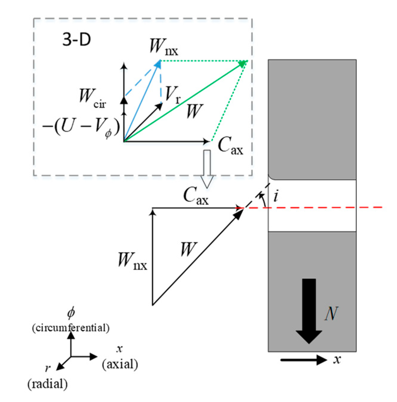
2. Theory of Rotating Orifices

Regardless of whether the orifice is stationary or rotating, the flow characteristics of the orifice are commonly described by the discharge coefficient, which is defined as the ratio of actual mass flow to the theoretical mass flow.
C d =   m ˙ a c t   m ˙ i d
The actual mass flow   m ˙ a c t is usually obtained by experiments or numerical calculations, while the theoretical flow   m ˙ i d is derived from the adiabatic isentropic equation. Its calculation formula is
m ˙ i d = p 1 t A T 1 t 2 γ ( γ 1 ) R [ ( p 2 s p 1 t ) 2 / γ ( p 2 s p 1 t ) ( γ + 1 ) / γ ]
where p 1 t and T 1 t are the total pressure and total temperature at the inlet of the orifice. p 2 s is the static pressure at the outlet. A is the cross-section area of the orifice. Then, the definition of the discharge coefficient can be expressed as follows:
C d =   m ˙ a c t T 1 t p 1 t A / 2 γ ( γ 1 ) R [ ( p 2 s p 1 t ) 2 / γ ( p 2 s p 1 t ) ( γ + 1 ) / γ ]
The corresponding theoretical axial velocity is given by
C ax = 2 γ γ 1 R T 1 t [ 1 ( p 2 s p 1 t ) γ 1 γ ]
In order to consider the effect of the rotational work on the discharge coefficient of orifices, the method of relative frame of reference is generally adopted. The calculation formula of the discharge coefficient C d and the theoretical axial velocity W a x is determined as follows:
C d =   m ˙ a c t T 1 t , rel p 1 t , rel A / 2 γ ( γ 1 ) R [ ( p 2 s p 1 t , rel ) 2 / γ ( p 2 s p 1 t , rel ) ( γ + 1 ) / γ ]
W ax = 2 γ γ 1 R T 1 t , rel [ 1 ( p 2 s p 1 t , rel ) γ 1 γ ]
In the above equations, p 1 t , rel and T 1 t , rel are total parameters in the relative frame of reference, which are calculated by
p 1 t , rel = p 1 t ( 1 + U 2 - 2 U V ϕ 2 c p T 1 t ) γ γ 1
T 1 t , rel = T 1 t ( 1 + U 2 - 2 U V ϕ 2 c p T 1 t )
where V ϕ is the circumferential velocity of the flow at the entrance of the orifice, which could be caused by pre-swirl. U is the circumferential velocity of the orifice as it rotates with the disk. Finally, the effect of rotation is characterized by the correlation of C d with U / W ax .
Figure 1 is a schematic diagram of the geometric structure for a typical rotating orifice with a circumferential inclination angle. In order to characterize the combined effect of rotation and circumferential inclination angle, Idris et al. [19,20] proposed a method of the plane incidence angle with reference to the concept of plane cascade, as shown in Figure 1. The specific calculation formula for the plane incidence angle ( i c ) is defined as
i c = arctan ( U / C ax ) - β 0
In addition, crossflows or pre-swirl flows can cause a more complicated flow condition at the inlet of the orifice, which results in a change in the form of the incidence angle. Figure 2 is a schematic diagram showing the velocity triangle in front of the axial orifice for this mixed flow condition. Since it is an axial orifice, the axis of the axial orifice can be considered as being in the same plane as the theoretical axial velocity ( C ax ) and the relative non-axial velocity ( W nx ). Therefore, the incidence angle in this case is calculated as
i = arctan ( W nx / C ax )
W nx = ( U V ϕ ) 2 + V r 2
However, orifices in the real engine, especially the film cooling orifices, are usually arranged with a specified Euler angle. In this case, Equation (10) will not be applicable because of the deflection of the orifice axis, and a new definition of the concept of the comprehensive incidence angle needs to be proposed to describe the effect of the Euler angle. Figure 3 shows a schematic of the definition of the comprehensive incidence angle. It is described as the angle between the axis of the orifice and the relative resultant velocity of the inlet flow, and the detailed calculation formula is given by the method of geometric space angle.
i = arccos ( C ax cos ( α 0 ) cos ( β 0 ) + ( U V ϕ ) cos ( α 0 ) sin ( β 0 ) V r sin ( α 0 ) ( U V ϕ ) 2 + V r 2 + C ax 2 )
In the above equation, α 0 is defined as the radial inclination angle, which is the angle between the axis of the orifice and its projection line on the x ϕ plane. β 0 is defined as the circumferential inclination angle, which is the angle between the projection line of the orifice axis on the x ϕ plane and the x-axis.

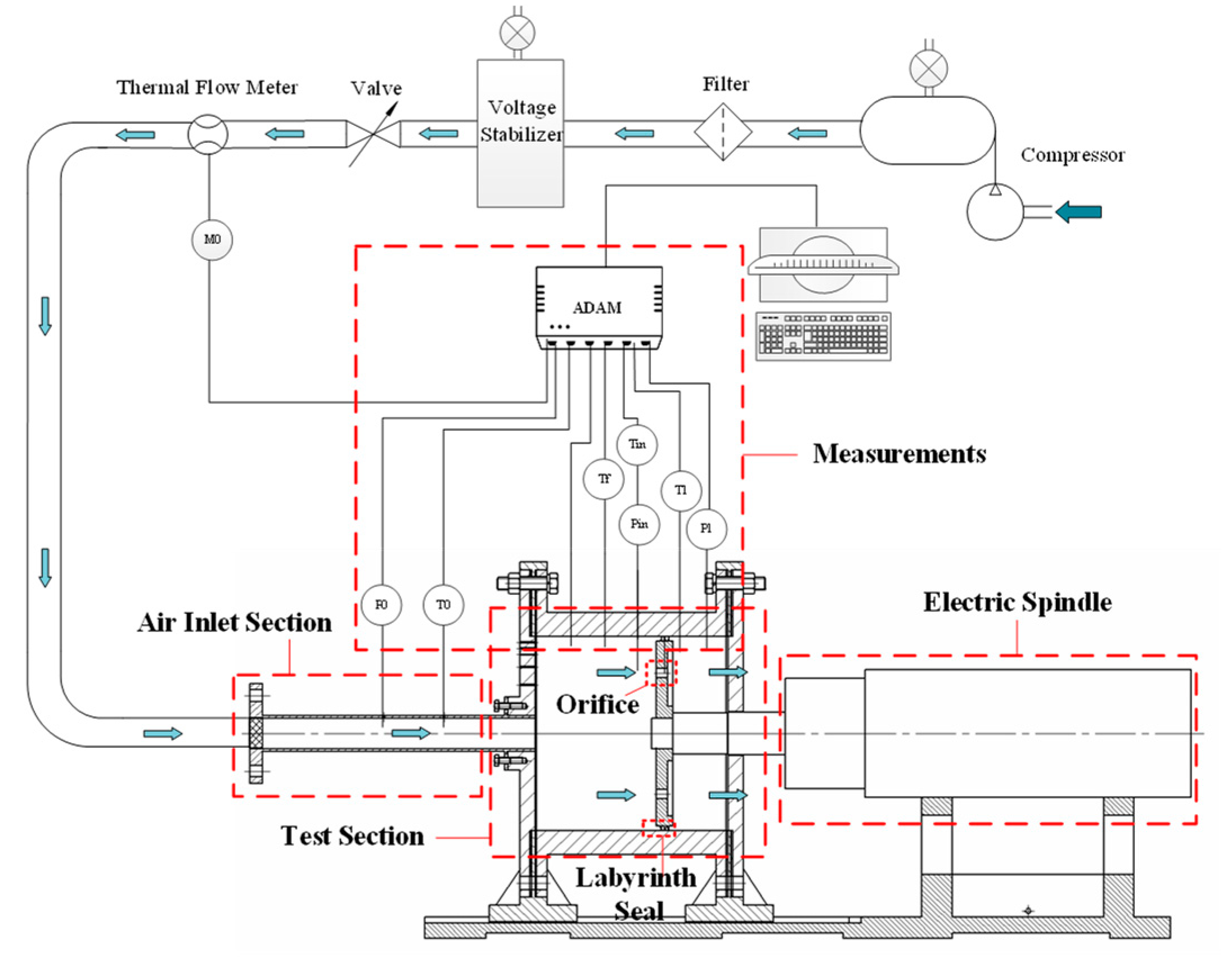
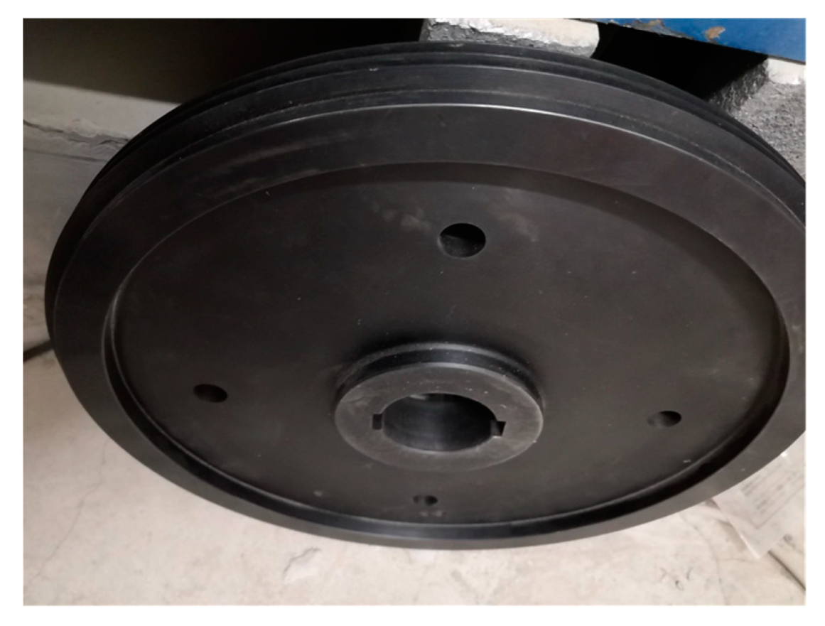
3. Experimental Apparatus

In order to investigate the discharge coefficient of the rotating orifice under different working conditions (pressure ratios and rotational speeds), a test rig was established in the School of Energy and Power Engineering, Beijing University of Aeronautics and Astronautics, as shown in Figure 4.
The test rig mainly consists of 3 parts: air source, experimental system, and measurement system. The compressed air is provided by the air compression station, which can continuously supply air of up to 1.3 MPa. The experimental system is mainly composed of the air inlet section, front and rear cover plates, a chamber, a rotating disk with labyrinth seal, and an electric spindle, etc. The air flow passes through a rectification mesh and enters into the air inlet duct. A thermal mass flow meter is arranged on the inlet pipe to measure the mass flow of air into the test section. The range of the flow meter is 0.005 kg/s to 0.1 kg/s with an accuracy of ±1% of the reading ±0.5% of the full scale. The pressure before and after the orifice is obtained by the high-precision dynamic adiabatic pressure sensors with an accuracy of ±0.1% in the range of 0–400 kPa. The temperature is measured by calibrated T-type thermocouples with a tolerance of ±0.2 K. The disk with labyrinth seals and 4 orifices distributed uniformly (shown in Figure 5) is driven by an electric spindle at a maximum speed of 3000 r/min. The measurement system consists of Advantech ADAM modules. The ADAM-4117 module and ADAM-4118 module are responsible for collecting current and voltage signals, and finally communicating with the computer through the Advantech ADAM-4520 module.

4. Numerical Calculation Method

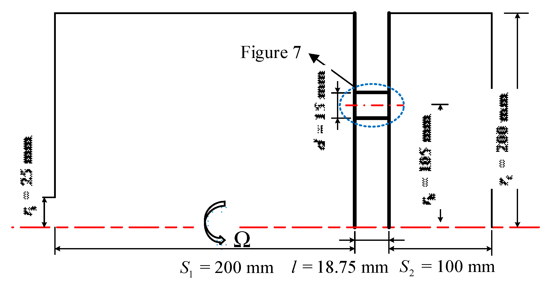
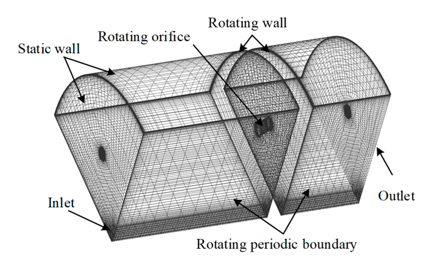
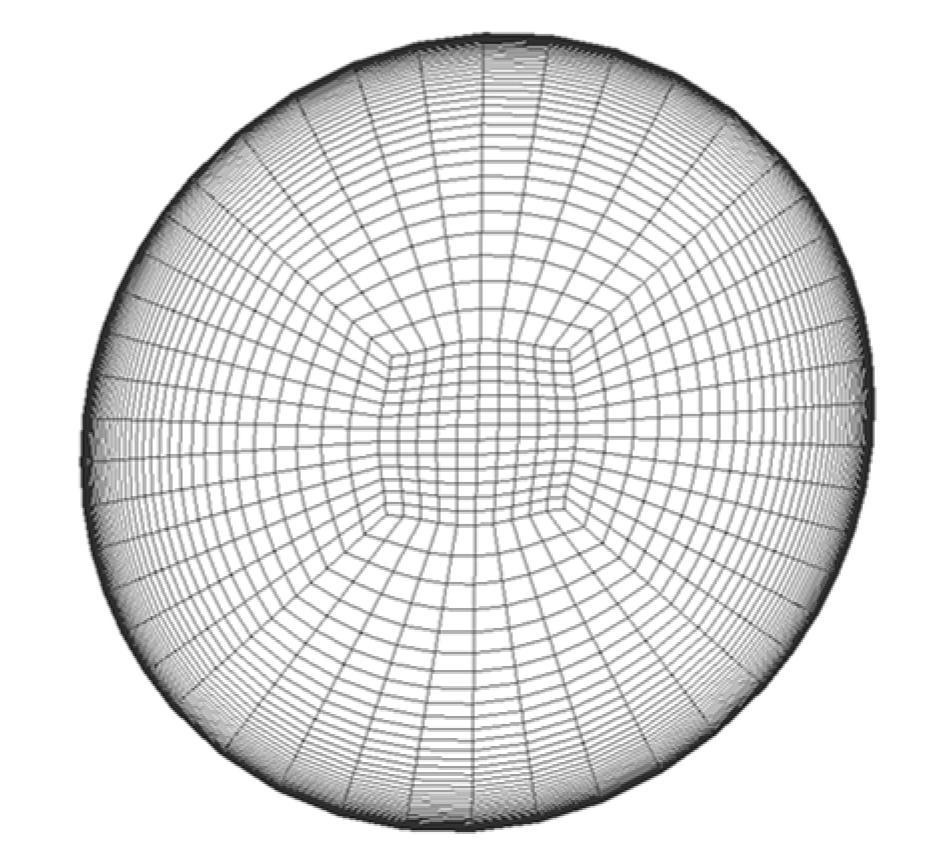
4.1. Geometric Model

Figure 6 shows a meridian view of the simplified geometric model for the rotating axial orifice (circumferential and radial inclination angles are 0). In the figure, the bold line part is the rotating wall, corresponding to the rotating orifice disk, on which four orifices are uniformly arranged along the circumferential direction. The thin line part is the stationary wall, which corresponds to the simplified cylindrical shell located on both sides of the rotating orifice. The structure of the orifice used in the geometric model was derived from the experiment conducted by Dittmann et al. [14]. The orifice length and diameter are 18.75 mm and 15 mm, respectively. The rotating orifice structure with a Euler angle is obtained by orienting the rotating orifice in Figure 6 with radial and circumferential inclination angles, as shown in Figure 7. The detailed parameters of the geometric model studied in this paper are shown in Table 2.

4.2. CFD Model and Boundary Conditions

The numerical research in this paper was carried out on ANSYS Workbench, and the main work involved the establishment of the parameterized geometric models, the delineation of the hexahedral meshes, and the numerical calculations.
Due to the fact that the geometry of the research object is variable, the software NX is used for the parametric design of the geometric model, where the design parameters mainly include the circumferential inclination angle and the radial inclination angle. Considering the symmetry of the structure with four periodically symmetrical axial orifices, only 1/4 of the model was investigated for the purpose of improving the calculation efficiency. The commercial software ANSYS ICEM-CFD was used to construct the hexahedral meshes of the models with different Euler angles and to refine the meshes close to walls. Figure 8 and Figure 9, respectively, show the schematic diagram of the overall grid and the enlarged grid of the orifice cross-section for the calculation model with a circumferential inclination angle of 15° and a radial inclination angle of 15°. The first layer grid size of the boundary layer on each wall is less than 0.05 mm. The first layer grid size of the inner wall on the rotating orifice is 0.01 mm with 1.1 growth rate. The results show that the Y+ of the wall for rotating orifice is almost equal to 1 at various operating conditions.
Numerical calculations were performed by the commercial software ANSYS CFX with the completely implicit formulas. The flow analysis type was the steady state and the calculation domain and boundaries are shown in Figure 8. The ideal gas was chosen as the working medium and the flow model was compressible. The cutting surfaces of the 1/4 model were set as the rotationally periodic interfaces, the total pressure and temperature were given at the inlet boundary, the back pressure was given at the outlet boundary, and the wall conditions were assumed to be adiabatic without slipping. The specific boundary condition settings are shown in Table 3.
The calculations were carried out in a rotating coordinate system. The whole fluid domain was set as a rotation domain with a rotational speed equal to the rotating disk. The rotating wall (disk) was set as a stationary wall, while the static wall was set with a rotating speed opposite to the rotation domain (counter rotating wall). Thus, in the stationary coordinate system, the stationary housing remains stationary while the rotating disk is still rotating. Under this condition, the contribution of the rotating coordinate system to the energy and momentum equations is considered. The energy equation was solved in terms of total energy and viscous heating effects were accounted for.
The BSL (Baseline k-Omega Model) model was chosen as the turbulence model and the inlet turbulence was medium turbulence with an intensity of 5%. The high-resolution with first-order advection scheme was adopted for the solution. The results indicate that the convergence residuals of the calculation results under various working conditions can generally reach less than 10-6. At the same time, the difference between inflow and outflow can reach below 10-5, and the flow is stable. In addition, the monitoring points of the velocity and total pressure set at 55 mm upstream of the orifice inlet never change anymore.

4.3. Verification of CFD Model

The verification of the established CFD model was carried out in two aspects. On one hand, the grid-independent solutions were investigated, and on the other hand, the simulation results were compared with experimental data reported in the published literature to verify the accuracy and reliability of the model.

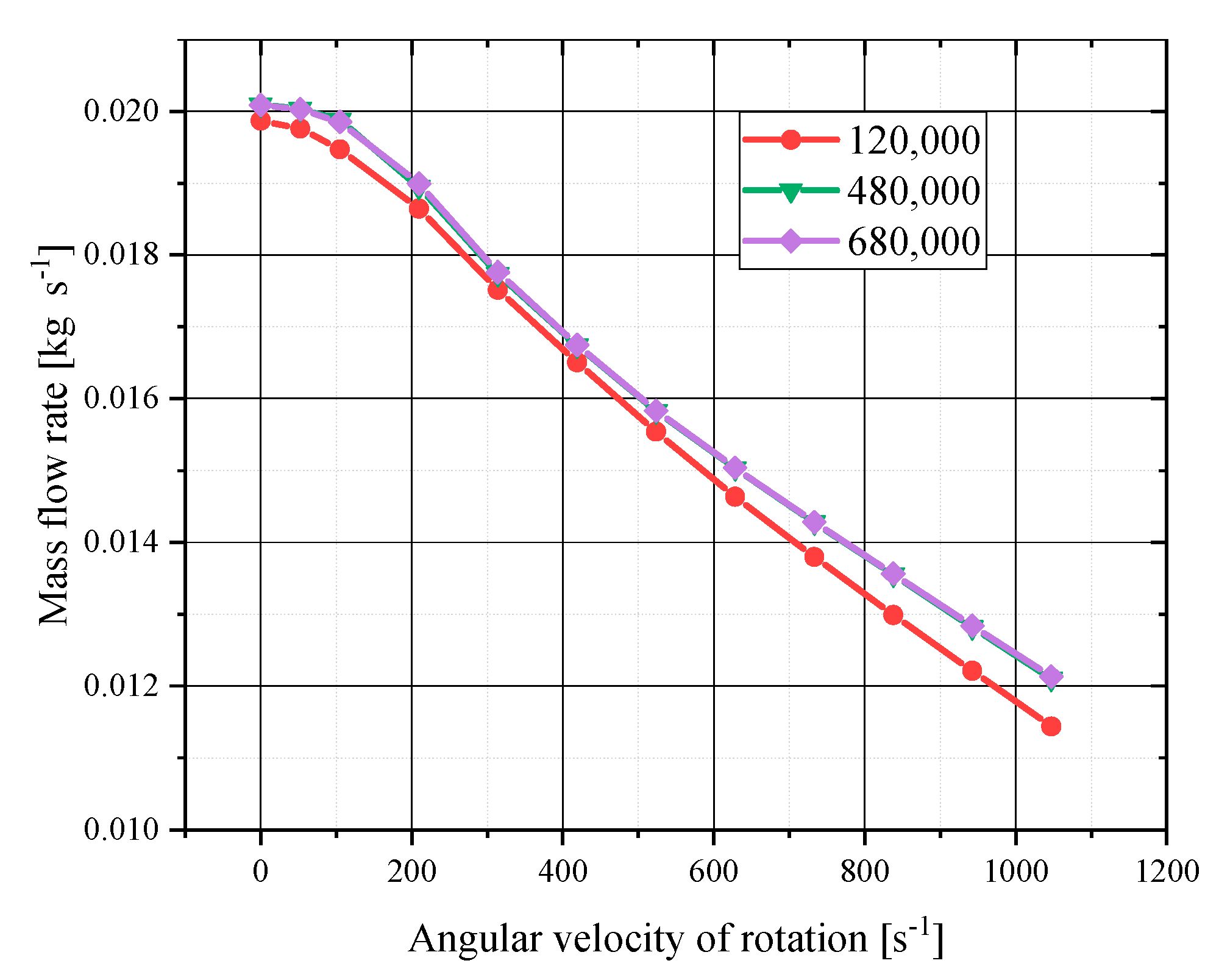
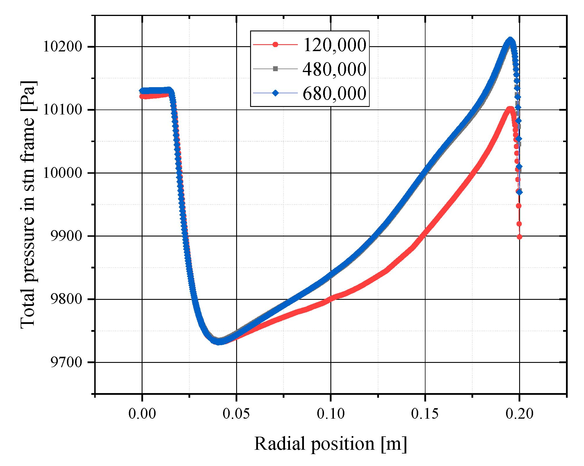
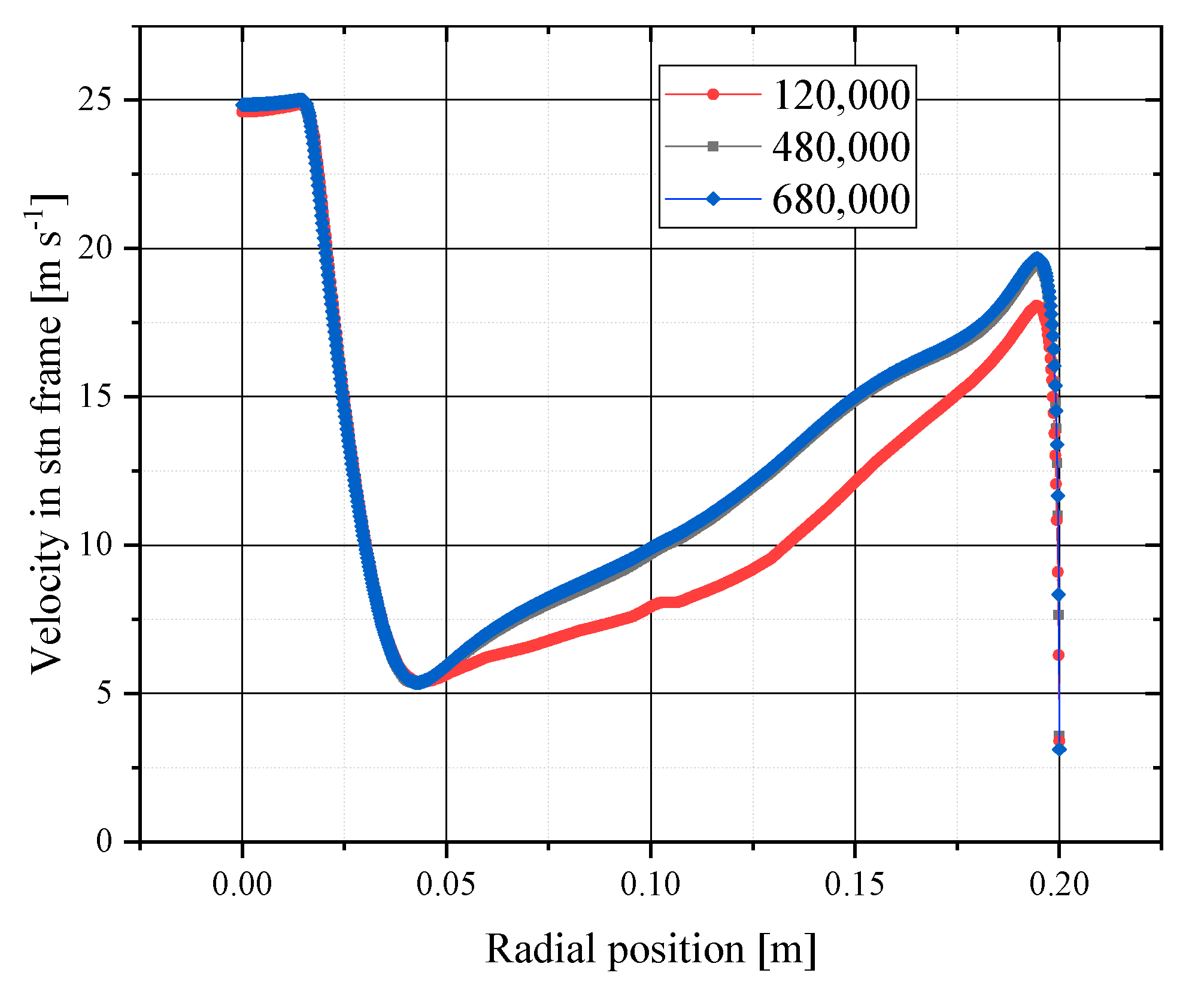
4.3.1. Verification of Grid Independence

In order to obtain a reliable and economical number of grids, it is necessary to work on the investigation of grid-independent solutions. In this paper, the control of the global grid density was realized by adjusting the global grid scaling factor under the condition that the boundary layer grid was kept unchanged. The final verification calculations were performed for comparison using models with grid numbers of 120,000, 480,000, and 680,000. The first comparison is the mass flow rate of the orifice, since it has the most intuitive effect on the flow coefficient of the orifice. Figure 10 shows the variation in the mass flow rate with the rotational speed of the orifice for the three sets of grids. The figure indicates that the calculation results of 120,000 grids show a large error with those of 480,000 and 680,000 grids, while the maximum relative error of mass flow rate between 480,000 and 680,000 grids is no more than 0.03%. Therefore, it can be believed that the mass flow rate basically never changes when the number of grids reaches 480,000. Moreover, the flow velocity and pressure distribution in the cavity were compared between the calculations. Figure 11 and Figure 12, respectively, show the flow velocity and pressure distributions on the radial line at 55 mm upstream of the orifice for the three sets of grids. The results reveal that the velocity and pressure distributions of the 480,000 and 680,000 grids are almost consistent, while the results of the 120,000 grids are lower than the values of the model with a refined grid. As a result, it is considered that the number of grids above 480,000 meets the grid independence requirements. In order to balance the calculation accuracy and load, a model with a grid number of 480,000 was used for the calculation. This method of determining grid-independent solutions introduced above is used for all calculations in this paper.

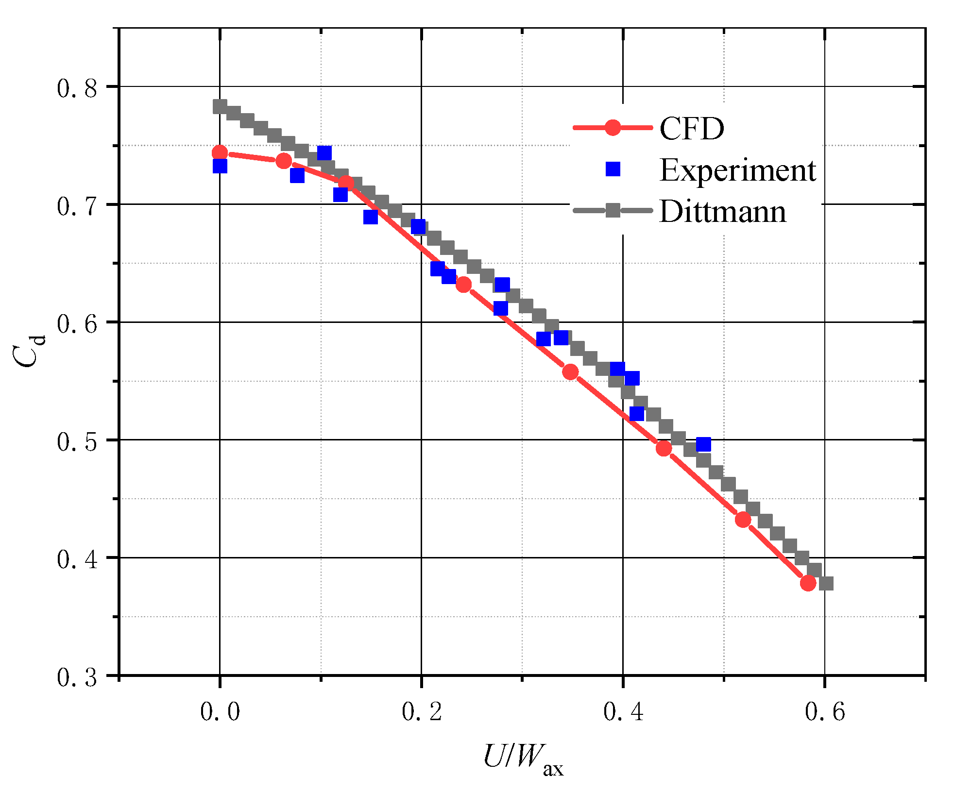
4.3.2. Verification of Computational Model Reliability

The results of calculations for the model, based on the grid-independent solution, were compared with the experimental results collected in this paper and published in the existing literature (Dittmann [14]) for the purpose of further ensuring the reliability and accuracy of the calculations. In the calculation, the inlet total temperature was 288.15 K, the pressure ratio between inlet and outlet was 1.05, the outlet back pressure was 101,325 Pa, and the rotational speed increased from 0 to 10,000 r/min with 1000 rpm increments. The calculation results were compared with the experimental data, as shown in Figure 13. The results indicate that the variation trend of the discharge coefficient for rotating orifices with U / W ax was basically consistent with the experimental data. The maximum relative error did not exceed 7%, while the minimum error was only 0.7%. The mean relative error between the experimental data and the calculated values over the entire range was around 2.8%, with a standard deviation of 2.1%. In addition, there was good agreement with the experimental fitting data of Dittmann [14]. The mean relative error was around 3.3%. The maximum relative error is 5.1% when the rotation speed is 0 r/min.

5. Results and Discussion

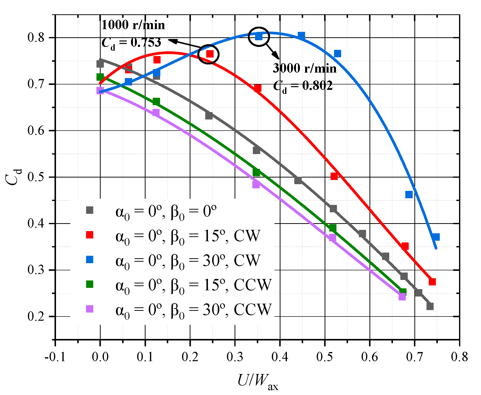
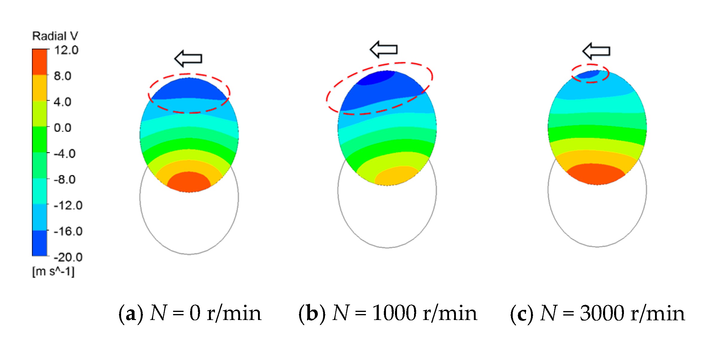
5.1. Effect of Circumferential Inclination Angle on the Discharge Coefficient

As mentioned above, the rotating orifice with the circumferential inclination angle only was investigated by Idris et al. [19,20] and the variation pattern of the discharge coefficient was given. However, the length-to-diameter ratio was not kept consistent in this study, and the data for large circumferential inclination angles did not cover the case of negative incidence angle. In this paper, therefore, the independent influencing factor of circumferential inclination angle was investigated under a fixed length-to-diameter ratio and the range of the incidence angle was extended.
Figure 14 shows a plot of the variation in the discharge coefficient for the rotating orifices with the relative velocity ratio under different circumferential inclination angles. Compared with the case of the straight orifice, it is found that two different trends of the discharge coefficient are caused by different directions of rotation speed for given circumferential inclination angles of 15° and 30°. The first variation rule is observed in the condition of counterclockwise rotation. The discharge coefficient for rotating orifices with circumferential inclination angles of 15° and 30° both decrease with the increase in rotational speed and the maximum discharge coefficient is found at the rotational speed of 0, which remains consistent with the pattern of the straight orifice. It is also noticed that the larger the circumferential inclination angle is, the smaller C d is for the same U / W ax . However, in the clockwise rotating condition, the trend of variation for C d changes. The relationship between C d and U / W ax of the rotating orifice with circumferential inclination angles of 15° and 30° shows a tendency of first increasing and then decreasing. Moreover, the maximum value of C d no longer appears at a rotational speed of zero, but at a certain unfixed rotational speed, which is related to the circumferential inclination angle. At the same time, the maximum value of C d is larger than that of the straight orifice, and the larger the circumferential inclination angle is, the larger the corresponding maximum value of the discharge coefficient is, which is caused by the work done to the airflow through rotation.
In the relative coordinate system, a circumferential deflection of the flow direction is caused by the rotation, and the flow direction after deflection may be further away from the orifice axis or closer to the orifice axis, depending on the magnitude and orientation of rotational speed. As shown in Figure 15, counterclockwise rotation (CCW) and clockwise rotation (CW) produce significantly different incidence angles for the same rotational speed, which explains the variable trends of the characteristic curves and the unfixed position of the maximum value in Figure 14.
The combined effect of rotation, circumferential inclination angle, and flow parameters on the discharge coefficient can be more clearly represented by the method of the comprehensive incidence angle. According to Equation (12), the formula for calculating the comprehensive incidence angle of the orifice with only the circumferential inclination angle is given by
i = arccos ( C a x cos ( β 0 ) + ( U V ϕ ) sin ( β 0 ) ( U V ϕ ) 2 + V r 2 + C a x 2 )
Based on the definition of the positive and negative incidence angles in Figure 15, the calculation is organized into a relationship between the discharge coefficient and the comprehensive incidence angle by Equation (13), as shown in Figure 16. The curves in the figure show that the discharge coefficient is higher the closer the comprehensive incidence angle is to 0°, no matter what the circumferential inclination angle is. The rotational speed required to reach the maximum discharge coefficient varies for different circumferential inclination angles. For a circumferential inclination angle of 30°, the discharge coefficient is close to the maximum value of around 0.805 at a rotational speed of 4000 r/min, which corresponds to a comprehensive incidence angle of −3.4°. Meanwhile, for a straight orifice at 4000 r/min, the comprehensive incidence angle is up to 20.4° and the discharge coefficient is only around 0.493, with a 39% reduction compared to the case of 30°. In addition, when the circumferential inclination angle is 15°, the maximum discharge coefficient is 0.765, achieved at a rotational speed of 2000 r/min, which corresponds to a comprehensive incidence angle of approximately −0.9°. Comparing the maximum values of the three sets of data, it is also found that the maximum discharge coefficient values are different for various circumferential inclination angles, and the larger the circumferential inclination angle, the larger the corresponding maximum value. This is because the larger the inclination angle, the higher the rotational speed required to reach the maximum discharge coefficient, i.e., to achieve the comprehensive incidence angle of 0°. At this point, more work is done on the flow and the flow losses are reduced, resulting in a rise in the discharge coefficient. Another interesting phenomenon is that the signs (positive and negative) of the comprehensive incidence angles have a significant effect on the discharge coefficient. When it is negative, the larger the circumferential inclination angle, the larger the discharge coefficient, but when it is positive, the tendency is shown that the larger the circumferential inclination angle, the smaller the discharge coefficient.
Figure 17 shows the velocity vectors and streamlines within the orifice for several different operating conditions in the x plane. It is observed that the separation region starts to form at the entrance of the orifice. The location of the separation region depends on the sign of the comprehensive incidence angle. For the negative case, the separation region is at the upper boundary (Figure 17a,d,g), while, for the positive case, the separation region is at the lower boundary (Figure 17c,f,i). Moreover, the size of the separation region depends on the absolute size of the comprehensive incidence angle (shown in Figure 17a–c). As the comprehensive incidence angle is close to 0° (Figure 17b,e,h), the fluid quickly reattaches to the inner wall of the orifice, which means that the separation region is small enough to be ignored. At this point, the actual cross-section flow area is the largest, and the discharge coefficient is also the largest.
In addition, the changes in the cross-section flow area can be better demonstrated by the velocity contour diagram of the orifice exit, as shown in Figure 18. In particular, it is convenient to analyze the relationship of the discharge coefficient for different circumferential inclination angles under a similar comprehensive incidence angle. For the case where the comprehensive incidence angle is similar and negative (shown in Figure 17a,d,g), as the circumferential inclination angle increases, the lower the rotational speed required to obtain the same negative incidence angle. As a result, the deflection angle of the airflow becomes smaller so that the flow resistance becomes smaller. Meanwhile, the separation region of low velocity within the orifice decreases, as shown in Figure 18a–c, and the discharge coefficient increases accordingly. On the contrary, as the comprehensive incidence angle is positive (Figure 17c,f,i), the higher the rotational speed required to obtain the same positive incidence angle with an increasing circumferential inclination angle. This makes the deflection angle of the airflow larger and the flow resistance greater. Eventually, the separation region gradually expands (shown in Figure 18d–f) and the discharge coefficient decreases.

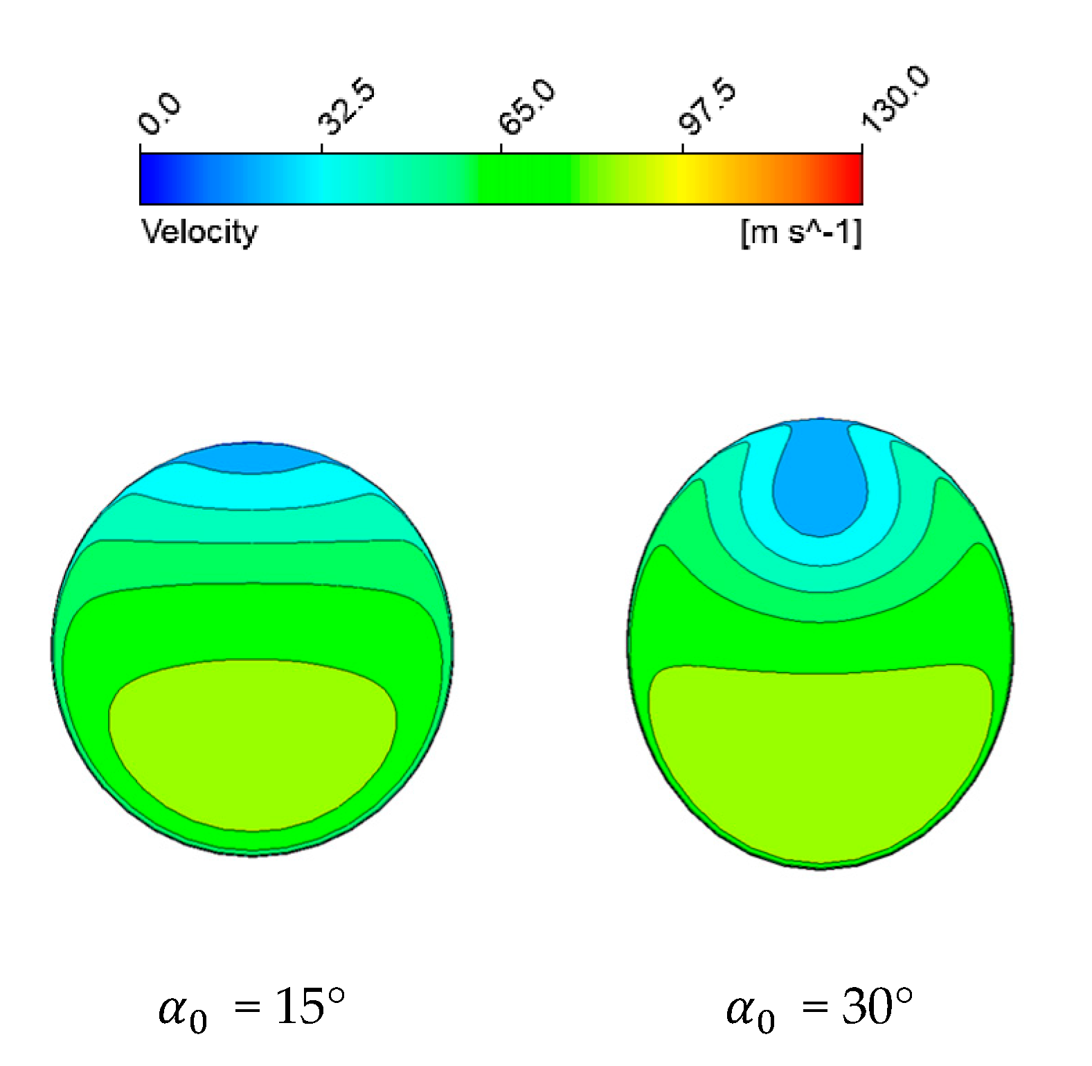
5.2. Effect of Radial Inclination Angle on the Discharge Coefficient

Figure 19 displays a diagram of the relationship between the discharge coefficient of rotating orifices and the relative velocity ratio under different radial inclination angles. As far as the general trend is concerned, the discharge coefficients all decrease with increasing relative velocity ratio, which is not affected by the direction of rotational speed. However, there is a region with a small increase in the discharge coefficient at low rotational speeds for orifices with radial inclination angle. In other words, the discharge coefficient at low rotational speeds is greater than that at the rotational speed of 0. This is due to the fact that the effect of radial flow caused by the pump effect is more pronounced at low rotational speeds. Figure 20 shows the contours of radial velocity at the orifice inlet, where the negative velocity is along the direction of the radial inclination. The radial inclination angles of the orifices in the figure are 30°, and the rotational speeds are 0 r/min, 1000 r/min, and 3000 r/min, respectively. It can be seen that the negative radial velocity at 1000 r/min is obviously larger than that at 0 r/min, which causes a deflection of the airflow in the direction of the radial inclination, thus reducing the flow resistance. As a result, the discharge coefficient at low rotational speed (1000 r/min) is larger than that at 0 r/min. However, as the rotational speed further increases, the radial flow is weakened. Meanwhile, the large circumferential flow resulting from high rotational speed further enhances the flow resistance. Therefore, the discharge coefficient decreases with a further increase in rotational speed.
In addition, some other conclusions can be derived by comparing the relationship of discharge coefficients between different radial inclination angles. It can be found that the larger the radial inclination angle is, the larger the discharge coefficient is for the same high velocity ratio, while the opposite is true for the low rotational speed. Figure 21 shows the contour plots of the velocity at the outlet section for the orifice with different radial inclination angles at 0 r/min. In these cases, the radial inclination angle is the dominant factor affecting the flow within the orifice. The larger the inclination angle, the larger the separation region, resulting in a lower discharge coefficient. However, the rotation will become the main factor that affects the flow in the case of high rotational speeds. Compared to an orifice with a small radial inclination angle (15°), a large radial inclination angle (30°) has a larger radial velocity component inside the orifice, resulting in a larger Coriolis force (shown in Figure 22). The separation region caused by the rotation is reduced by this Coriolis force, which increases the actual cross-section flow area and improves the discharge coefficient (shown in Figure 23).
In order to provide a clearer representation of the combined effect of the radial inclination angle, rotation, and flow parameters on the discharge coefficient, the method of comprehensive incidence angle is adopted. Based on Equation (12), the calculation formula for the comprehensive incidence angle under the condition of only the radial inclination angle can be obtained by
i = arccos ( C ax cos ( α 0 ) V r sin ( α 0 ) ( U V ϕ ) 2 + V r 2 + C a x 2 )
The change in circumferential velocity is much more pronounced than that of radial velocity, as the radial crossflow is not included in this computational study. Therefore, the positive and negative sign of the comprehensive incidence angle is still determined by the definition in Figure 15, i.e., the sign is given by the deflection angle of the fluid along the circumferential direction compared to the circumferential inclination angle of the orifice. Then, the relationship between the discharge coefficient and the comprehensive incidence angle for the rotating orifice with radial inclination angles is shown in Figure 24. It is obvious that the discharge coefficient gradually increases with the decrease in the absolute value for the comprehensive incidence angle, and the closer the incidence angle is to 0°, the greater the flow coefficient. (As there is no radial crossflow in this paper, the airflow direction cannot compensate for the redial inclination angle of the orifice; thus, the comprehensive incidence angle cannot reach 0°.) Within the calculation conditions, the incidence angle at low rotational speed (1000 r/min) is even lower than that at 0 r/min, resulting in a higher discharge coefficient. This phenomenon is also the reason for the rising range of the discharge coefficient in Figure 19. In addition, there is always a rule that the larger the radial inclination angle is, the larger the discharge coefficient is for the same comprehensive incidence angle.
The change in discharge coefficient with rotational speed for the same radial inclination angle is further analyzed by presenting graphs of streamlines and velocity contours for different cross-sections, as shown in Figure 25. The combined effect of radial inclination and rotation results in different comprehensive incidence angles, which change the discharge coefficient.
In the case without radial flow, generally, the higher the rotational speed is, the higher the comprehensive incidence angle is, and the smaller the discharge coefficient is. As shown in Figure 25 for the cases of 0 r/min and 3000 r/min, the separation region in both the meridian section and circumferential cross-section at 3000 r/min is larger than that at 0 r/min. Meanwhile, it can also be clearly seen from the velocity contours of the outlet section (Figure 25g,i) that the flow in the orifice at 3000 r/min is strongly influenced by rotation and the separation region with low velocity is also larger. This results in a smaller actual cross-section flow area and a lower discharge coefficient.
However, at a low rotational speed (1000 r/min), a special phenomenon is observed in which the comprehensive incidence angle decreases and the discharge coefficient increases. This is because the separation region in the circumferential cross-section caused by rotation is almost negligible. At the same time, the effect of radial flow generated by the pump effect is more pronounced, resulting in a weakening of the separation region caused by the radial inclination angle (shown in Figure 25b). It can also be seen in Figure 25h that the separation region with low velocity is squeezed and the through-flow region with high velocity becomes larger. The above analysis further proves that the coupling effect of radial inclination angle, radial flow, and rotation can be reflected more clearly by the comprehensive incidence angle. Therefore, it is believed that the method of the comprehensive incidence angle is more suitable for describing the characteristic of the rotating orifice with Euler angles.
Figure 26 presents the streamlines and velocity contours of different sections for the rotating orifice under the three operating conditions. The comprehensive incidence angles for these three operating conditions are essentially equal, but the discharge coefficient increases with increasing radial inclination angle. The presence of the radial inclination angle results in a larger separation region at the meridian section of the inclined orifice than that of the straight orifice (Figure 26a–c). However, it can be noted from the velocity contour (Figure 26g–i) that the core of the separation region inside the orifice is not at the upper end of the orifice exit at this point, but rotates to the side. This phenomenon indicates that the flow in the orifice is more significantly influenced by the rotation in the three cases mentioned above. In order to keep the same comprehensive incidence angle, the larger the radial inclination angle, the smaller the rotational speed required. The low rotational speed leads to a reduction in the separation region. At the same time, the weakening effect of the Coriolis force causes a further reduction in the separation region inside the orifice with a large radial inclination angle, resulting in a significant increase in the discharge coefficient as well (Figure 26d–f). Moreover, it can also be clearly found in Figure 26g–i that the smaller the radial inclination angle is, the more low-velocity fluid is in the orifice for the same comprehensive incidence angle, which implies a larger separation region and a lower discharge coefficient.

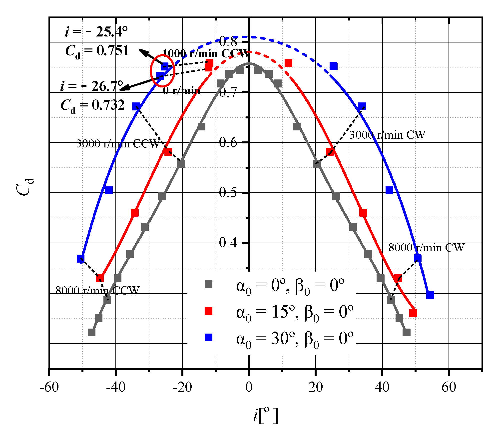
5.3. Effect of the Compound Angle on the Discharge Coefficient

The existence of the compound angle (circumferential and radial inclination angles exist at the same time) leads to a more complex flow in the rotating orifice, which is due to the fact that there are more dominant factors affecting the flow. As is revealed in the above analysis, the combined effect of rotation, circumferential inclination angle, radial inclination angle, and flow on the discharge coefficient can be better characterized by the comprehensive incidence angle. The complete formula for the discharge coefficient of an orifice with compound angles can be written as
i = arccos ( C ax cos ( α 0 ) cos ( β 0 ) + ( U V ϕ ) cos ( α 0 ) sin ( β 0 ) V r sin ( α 0 ) ( U V ϕ ) 2 + V r 2 + C ax 2 )
In order to present the effect of the comprehensive incidence angle on the discharge coefficient of rotating orifices with different compound angles more clearly, two types of cases are compared and analyzed in this section. One is the case of the same radial inclination angle but different circumferential inclination angle (same α 0 but different β 0 ), and the other is the case of the same circumferential inclination angle but different radial inclination angle (same β 0 but different α 0 ).

5.3.1. Variation in Discharge Coefficients for the Same α 0 and Different β 0

The relationships between the discharge coefficient and the comprehensive incidence angle for the same α 0 and different β 0 are shown in Figure 27. It can be seen that the discharge coefficient decreases with the increase in the absolute value of the comprehensive incidence angle at each compound angle. The closer the comprehensive incidence angle is to 0, the larger the discharge coefficient is. In addition, one more point worth paying attention to is that the larger β 0 is, the larger the discharge coefficient is for the same negative comprehensive incidence angle. However, for a positive incidence angle, an intersection point exists between different curves of the discharge coefficient, and the size relationship between the discharge coefficient before and after this intersection point is opposite.
To analyze the reasons for the formation of the above rules, the streamlines and velocity contours of different cross-sections under three cases are provided with a fixed radial inclination angle of 15° as an example, as shown in Figure 28. Case 1 and Case 2 are the cases with the same Euler angles and different comprehensive incidence angles. It is obvious that the comprehensive incidence angle of Case 1 is significantly smaller than that of Case 2, resulting in a smaller separation region (shown in Figure 28c,f). This indicates that the actual cross-section flow area increases and the discharge coefficient grows larger.
Case 2 and Case 3 are the cases with the same negative comprehensive incidence angle. The comparison between the two cases reveals that the separation in the meridian section caused by the radial inclination angle is small and the fluid can easily reattach to the wall (shown in Figure 28d,g), while the separation region in the circumferential cross-section is significantly larger (Figure 28e,h). This phenomenon suggests that the dominant factors affecting the flow are rotation and the circumferential inclination angle at this moment. Another important point is that the separation region of Case 2 is distinctly larger than that of Case 3. This is due to the fact that Case 2, with a small circumferential inclination angle ( β 0 = 15°), requires a higher rotational speed to obtain the same negative comprehensive incidence angle, which ultimately results in a larger separation region than Case 3 ( β 0 = 30°). It is also evident from the velocity contour plots of the outlet for both cases (Figure 28f,i) that the separation region with low velocity of Case 2 is obviously larger than that of Case 3, which further explains the rule that the larger β 0 is, the larger the discharge coefficient is for the same α 0 with a same negative comprehensive incidence angle. As for the same positive incidence angle, the reason for the presence of the intersection point is that the large inclination angle needs a high rotational speed to reach the same positive comprehensive incidence angle as the small inclination angle, resulting in an inversion of the relationship between the discharge coefficients.
To analyze the reasons for the formation of the above rules, the streamlines and velocity contours of different cross-sections under three cases are provided with a fixed radial inclination angle of 15° as an example, as shown in Figure 28. Case 1 and Case 2 are the cases with same Euler angles and different comprehensive incidence angles. It is obvious that the comprehensive incidence angle of Case 1 is significantly smaller than that of Case 2, resulting in a smaller separation region (shown in Figure 28c,f). This indicates that the actual cross-section flow area increases and the discharge coefficient grows larger.
Case 2 and Case 3 are the cases with the same negative comprehensive incidence angle. The comparison between the two cases reveals that the separation in the meridian section caused by the radial inclination angle is small and the fluid can easily reattach to the wall (shown in Figure 28d,g), while the separation region in the circumferential cross-section is significantly larger (Figure 28e,h). This phenomenon suggests that the dominant factors affecting the flow are rotation and the circumferential inclination angle at this moment. Another important point is that the separation region of Case 2 is distinctly larger than that of Case 3. This is due to the fact that Case 2, with a small circumferential inclination angle ( β 0 = 15°), requires a higher rotational speed to obtain the same negative comprehensive incidence angle, which ultimately results in a larger separation region than Case 3 ( β 0 = 30°). It is also evident from the velocity contour plots of the outlet for both cases (Figure 28f,i) that the separation region with low velocity of Case 2 is obviously larger than that of Case 2, which further explains the rule that the larger β 0 is, the larger the discharge coefficient is for the same α 0 with a same negative comprehensive incidence angle. As for the same positive incidence angle, the reason for the presence of the intersection point is that the large inclination angle needs a high rotational speed to reach the same positive comprehensive incidence angle as the small inclination angle, resulting in an inversion of the relationship between the discharge coefficients.

5.3.2. Variation in Discharge Coefficients for the Same β 0 and Different α 0

Figure 29 shows the relationship between the discharge coefficient and the comprehensive incidence angle for the same β 0 and different α 0 conditions. The discharge coefficient still decreases with the increase in the absolute value of the comprehensive incidence angle, which is consistent with the conclusion in the previous section. It is also found that the larger α 0 is, the larger the discharge coefficient at the same comprehensive incidence angle.
The cases with a fixed circumferential angle of 15° ( β 0 = 15°) are selected as an example for the analysis. The streamlines and velocity contours of the different cross-sections for two different cases are presented in Figure 30. The comprehensive incidence angles of Case 1 and Case 2 are the same, but the compound angles and rotational speeds are different, resulting in different main factors affecting the flow. The separation region in the circumferential section of Case 1 is more obvious than that in the meridian section (Figure 30a,b), indicating that the flow is mainly influenced by rotation and the circumferential inclination angle. It can also be seen from the velocity contour of the outlet (Figure 30c) that the core of the separation region with low velocity is deflected to the right boundary. Unlike Case 1, the flow in Case 2 is mainly influenced by the radial inclination angle. It is clearly seen from Figure 30d that there is a large separation region on the meridian section of Case 2, while the separation region in the circumferential cross-section is small and the fluid quickly reattaches to the surface of the inner wall (Figure 30e). This is attributed to two reasons. One is the reduction in rotational speed for the purpose of achieving the same comprehensive incidence angle. The other is that the effect of rotation is further weakened by the Koch force, which is produced by the large radial velocity resulting from the large radial inclination angle. Meanwhile, the separation region with low velocity is mainly located at the top of the orifice outlet (Figure 30f), which further proves that the flow in Case 2 is mainly influenced by the radial inclination angle. Lastly, the separation region of Case 1 is significantly larger than that of Case 2 when comparing Figure 30c,f, which illustrates the rule that the larger α 0 is, the larger the discharge coefficient is for the same β 0 with the same comprehensive incidence angle.

5.4. A General Calculation Model of the Rotating Orifice Considering the Effect of the Comprehensive Incidence Angle

The factors affecting the discharge coefficient of the orifice mainly include geometric structures (length-to-diameter ratio l / d , inlet radius and chamfering, Euler angle) and flow parameters (Reynolds number Re , pressure ratio   π , crossflow, pre-swirl, and rotation). A large number of formulas have been summarized in the previous literature to describe the effects of different factors, but the combined effect of Euler angles and rotation has not been reported. In this part, a general model of the discharge coefficient for a rotating orifice is developed with the concept of the comprehensive incidence angle and the method of weighting factor considering the single factor. The comprehensive incidence angle in the model is determined by various factors including the Euler angle, cross-flow, pre-swirl, and rotation.
The curves of the discharge coefficient at each Euler angle are different and the trends are also varied for positive and negative signs of the comprehensive incidence angle. Therefore, polynomial fitting of the discharge coefficients for positive and negative comprehensive incidence angle conditions at different Euler angles is carried out, respectively, and the fitting form can be expressed as
C d = a + b × i + c × i 2 + d × i 3 + e × i 4
The parameters to be determined in the formula are listed in Table A1 in the Appendix A.
The relationship between the discharge coefficient and the comprehensive incidence angle for other different Euler angles ( 0 ° α 0 30 ° ,   0 ° β 0 30 ° ) can be obtained by interpolation. Meanwhile, the corresponding incremental relation of the discharge coefficients caused by the Euler angles is also derived.
C d , α 1 = α 0 - 0 15 0 × C d , 15 - 0 + 15 - α 0 15 0 × C d , 0 - 0 C d , α 2 = α 0 - 0 15 0 × C d , 15 - 15 + 15 - α 0 15 0 × C d , 0 - 15   0 α 0 < 15
C d , α , β = β 0 - 0 15 0 × C d , α 2 + 15 - β 0 15 0 × C d , α 1   0 β 0 < 15
Δ C d , α , β = C d , α , β - C d , 0 - 0
The equations above are based on the example of 0 ° α 0 < 15 ° and 0 ° β 0 < 15 ° , and the interpolation relations are similar for the rest of the range of Euler angles. The final discharge coefficients for different comprehensive incidence angles at different Euler angles are obtained from the incremental relationship.
C d = Δ C d , α , β + C d , i , sharp   0 α 0 < 15
where Δ C d , α , β is the increment in the discharge coefficient under the influence of Euler angles for different comprehensive incidence angles, and C d , i , sharp is the discharge coefficient for straight orifices provided by experimental data at different incidence angles. Based on the above methods and correlations, a general calculation model of the rotating orifice can be developed considering the effect of the comprehensive incidence angle.
In order to verify the model established in this paper, a comparison between the calculation results of the model and the experimental data was performed for the test objects in the literature. The main parameters of the rotating orifices for the comparison are shown in Table 4.
The results of the comparison are shown in Figure 31. The maximum relative error between the calculation results and the experimental data is approximately 11%, which occurs at the condition that the circumferential inclination angle is 15° with a positive comprehensive incidence angle. A possible reason for the presence of the largest error is that the calculation data are used as part of the model, and a rapid decline in the discharge coefficient occurred in this operating condition. However, the maximum relative error does not exceed 6% for all other operating conditions and the calculation results are in overall good agreement with the experimental results. The calculation results can reflect the trend that the discharge coefficient increases as the comprehensive incidence angle tends to 0, which also verifies the feasibility and reliability of the modeling method. Unfortunately, as there are no available experimental data in the published literature demonstrating the effect of the Euler angles and rotation on the comprehensive incidence angles, further experiments are still needed to refine the model at a later stage.

6. Conclusions

In this paper, the combined effects of Euler angles (different radial inclination angles and different circumferential inclination angles) and rotation on the flow characteristics of orifices are numerically investigated. The concept of the comprehensive incidence angle is put forward to express this combined effect clearly. The effects of the circumferential inclination angle, radial inclination angle, and compound angle on the discharge coefficient of the rotating orifice are discussed using the concept of the comprehensive incidence angle. Finally, a general calculation model for rotating orifices considering the effect of the comprehensive incidence angle is developed and validated. The main conclusions are as follows.
(1)
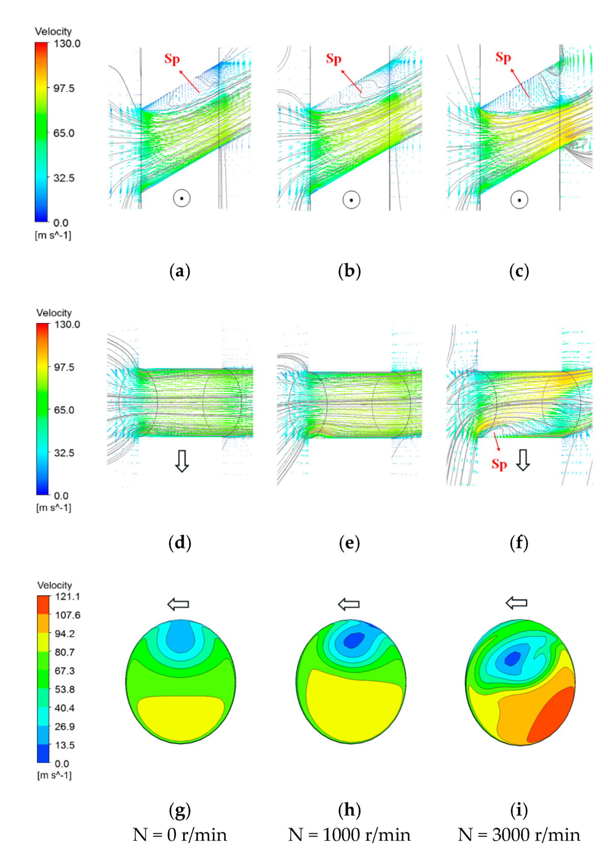
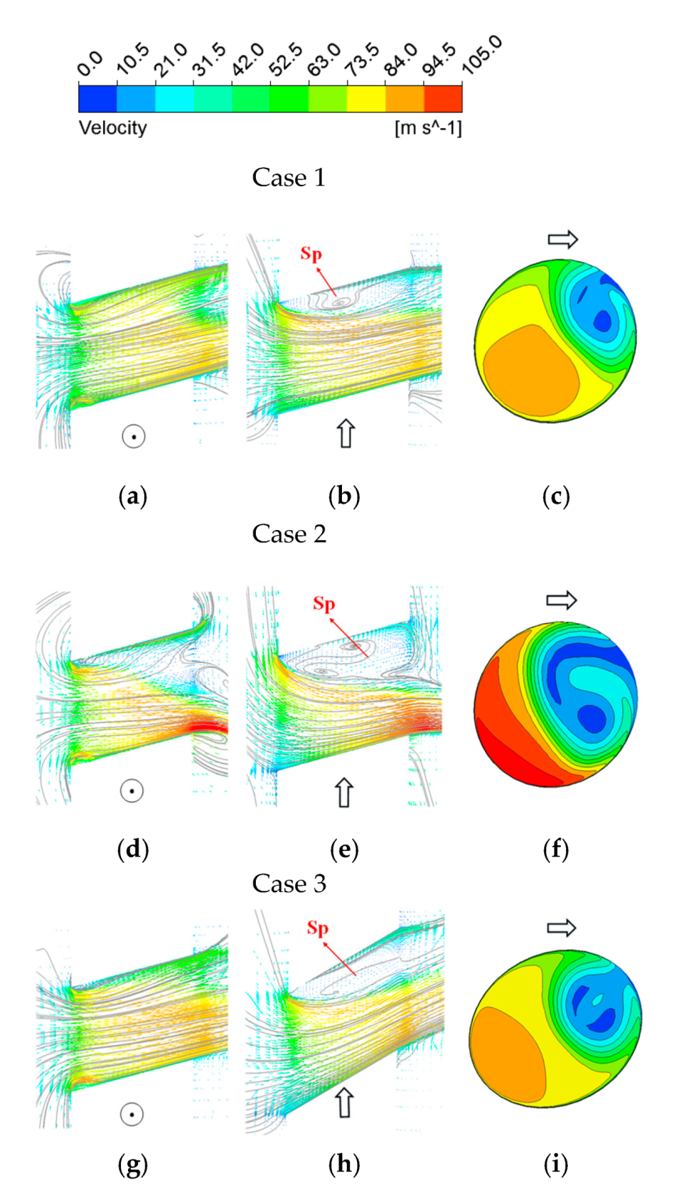
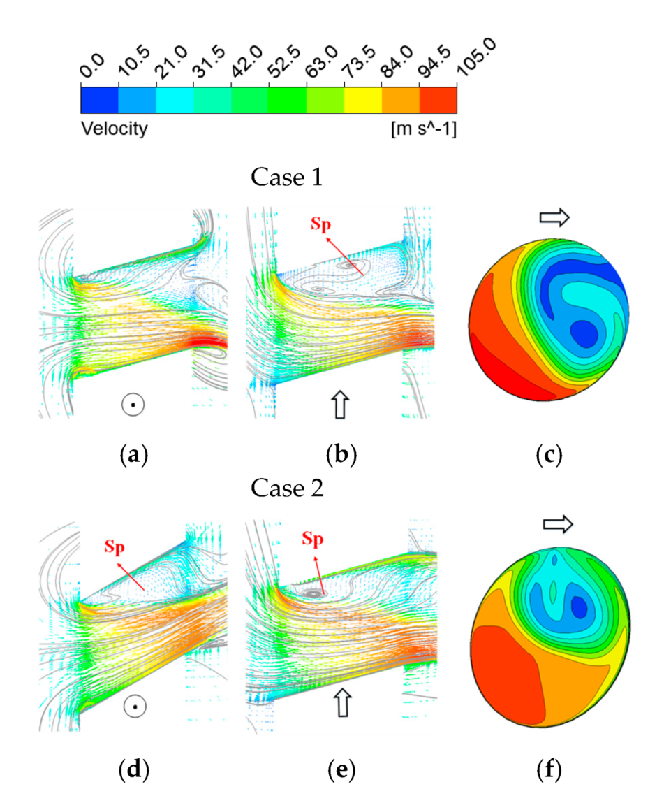
The Euler angles have a significant effect on the discharge coefficient of the rotating orifices. The flow separation caused by the Euler angle may change the actual cross-section flow area and result in a decrease in the discharge coefficient.
(2)
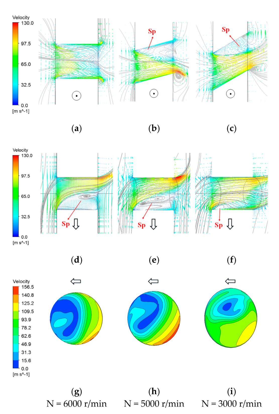
For the circumferential inclination angle, the magnitude and direction of the rotational speed are the main factors affecting the flow separation in the circumferential cross-section. For the radial inclination angle, the pump effect arising from rotation can reduce the flow separation region at the meridian section and improve the discharge coefficient to some extent.
(3)
A large radial inclination angle results in a greater Coriolis force, which may weaken the flow separation effect caused by rotation and the circumferential inclination angle, thus improving the discharge coefficient.
(4)
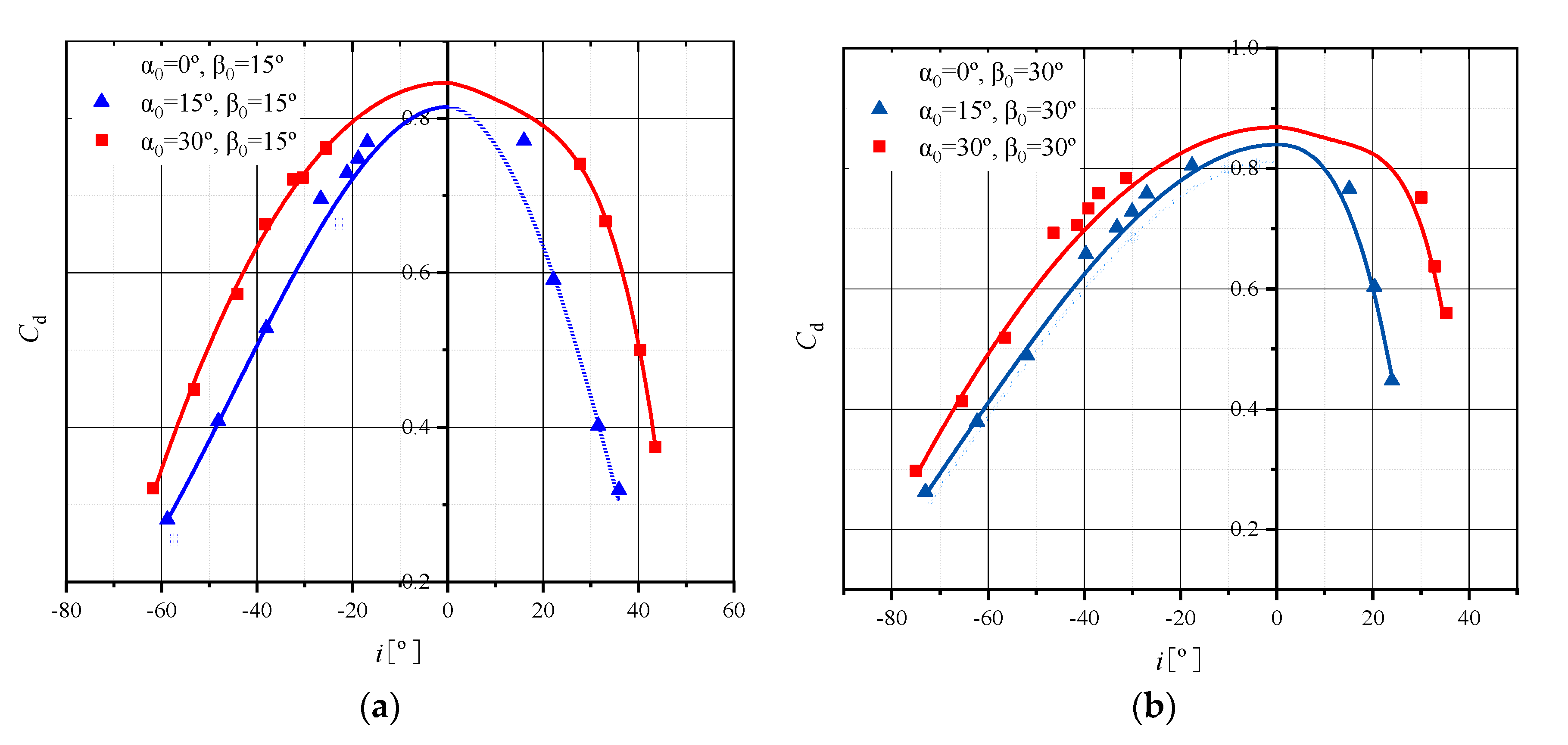
The comprehensive incidence angle is determined by the Euler angle (radial inclination angle and circumferential inclination angle) and rotation. It is clear that the discharge coefficient of the orifice increases with the decline in the comprehensive incidence angle. The discharge coefficient of orifices would reach the peak when the comprehensive incidence angle is 0.
(5)
The general calculation model of rotating orifices considering the effect of the comprehensive incidence angle is developed. The overall relative error between the calculation results and the experimental data in the published literature is within 6%, which meets the requirements of engineering design in the secondary air system.
However, there are no more available experimental data considering the combined effects of parameters such as Euler angles, cross-flows, pre-swirl flows, and rotation in the published literature. Therefore, experiments are still needed to refine the model at a later stage.

Author Contributions

J.W. completed the experimental study, numerical calculation and model building, and finally wrote this paper. T.Q., P.L. and S.D. contributed some reviews and funding. All authors have read and agreed to the published version of the manuscript.

Funding

This research was funded by Project MJ-2018-D-21, supported by the Ministry of Industry and Information Technology of the People’s Republic of China. This research also was funded by a major project of the National Science Foundation of China (No. 61890923).

Institutional Review Board Statement

Not applicable.

Informed Consent Statement

Not applicable.

Data Availability Statement

The data used to support the findings of this paper are contained in the text, and some of the cited data can be found in the public literature.

Acknowledgments

The authors express their sincere gratitude to Luoyang Bearing Group Co., Ltd. (No. 961, Guanlin Road, Luolong District, Luoyang City, Henan Province, China) for providing the electric spindle.

Conflicts of Interest

The authors declare no conflict of interest.

Nomenclature

A Cross-sectional area [ m 2 ]
c p Specific heat at constant pressure [ J / ( kg Δ K ) ]
C ax Axial velocity in the abs. frame of reference [ m / s ]
C d Discharge coefficient
d Diameter of orifice [m]
i Comprehensive incidence angle [ ° ]
i c Circumferential incidence angle [ ° ]
l Length of orifice [m]
m Mass flow rate [ kg / s ]
N Disk rotating speed [ r / min ]
p Pressure [ N / m 2 ]
r c Radius of the cavity [m]
r h Pitch radius [m]
r i Inlet radius of the cavity [m]
r in Inlet radius of the orifice [m]
R Ideal gas constant [ J / ( kg Δ K ) ]
ReReynolds number
SpSeparation region
T Temperature [ K ]
U Orifices rotating velocity [ m / s ]]
V ϕ Circumferential velocity [ m / s ]]
V r Radial velocity [ m / s ]
w Chamfering depth
W Relative velocity [ m / s ]
W ax Axial velocity in the rel. frame of reference [ m / s ]
Greek symbols
α 0 Radial inclination angle [ ° ]
β 0 Circumferential inclination angle [ ° ]
γ Specific heat ratio
δ Angle of chamfering [ ° ]
θ Pre-swirl angle [ ° ]
Subscripts
act actual
cir circumferential
id ideal
in , out inlet, outlet
nx non-axial
rel the rel. frame of reference
s static
t total
1 , 2 upstream, downstream of orifices

Appendix A

Table A1. Fitting parameters for the discharge coefficients of different Euler angles.
α 0 = 0 ° ,   β 0 = 0 ° α 0 = 0 ° ,   β 0 = 15 ° α 0 = 0 ° ,   β 0 = 30 °
iPositiveNegativePositiveNegativePositiveNegative
a0.7570.7570.7730.7730.8110.811
b00−0.01540−0.02450
c−8.62 × 10⁻⁴−8.62 × 10−40−2.78 × 10−40−1.63 × 10⁻⁴
d2.4 × 10−5−2.4 × 10−50−2.09 × 10−60−7.48 × 10⁻⁷
e−2.29 × 10⁻⁷−2.29 × 10−70000
α 0 = 15 ° ,   β 0 = 0 ° α 0 = 15 ° ,   β 0 = 15 ° α 0 = 15 ° ,   β 0 = 30 °
iPositive/NegativePositiveNegativePositiveNegative
a0.780.8150.8150.840.84
b2.35 × 10−50000
c−3.36 × 10⁻⁴−5.06 × 10⁻⁴−2.75 × 10⁻⁴−2.24 × 10⁻⁴−1.66 × 10⁻⁴
d−8.16 × 10−83.15 × 1068−2.04 × 10⁻⁶−1.88 × 10⁻⁵−7.73 × 10⁻⁷
e5.35 × 10−8----
α 0 = 30 ° ,   β 0 = 0 ° α 0 = 30 ° ,   β 0 = 15 ° α 0 = 30 ° ,   β 0 = 30 °
iPositive/NegativePositiveNegativePositiveNegative
a0.810.8460.8460.8690.869
b−2.93 × 10⁻⁴−8.42 × 10−4000
c−1.05 × 10⁻⁴−2.1 × 10⁻⁴−1.21 × 10⁻⁴−3.8 × 10⁻⁴−1.11 × 10⁻⁴
d1.87 × 10−71.08 × 10−52.98 × 10−72.72 × 10⁻⁵−1.13 × 10⁻⁷
e−2.63 × 10⁻⁸−2.57 × 10−706.85 × 10−70

References

  1. Sehra, A.K.; Whitlow, W. Propulsion and power for 21st century aviation. Prog. Aerosp. Sci. 2004, 40, 199–235. [Google Scholar] [CrossRef]
  2. Setlak, L.; Kowalik, R.; Lusiak, T. Practical Use of Composite Materials Used in Military Aircraft. Materials 2021, 14, 4812. [Google Scholar] [CrossRef] [PubMed]
  3. Lewis, P.; Wilson, M.; Lock, G.D.; Owen, J.M. Effect of radial location of nozzles on performance of pre-swirl systems: A computational and theoretical study. J. Power Energy 2008, 223, 179–190. [Google Scholar] [CrossRef]
  4. Hay, N.; Lampard, D. Discharge coefficient of turbine cooling holes: A review. ASME J. Turbomach. 1998, 120, 314–319. [Google Scholar] [CrossRef]
  5. Lichtarowicz, A.; Duggins, R.K.; Markland, E. Discharge Coefficients for Incompressible Non-Cavitating Flow through Long Orifices. J. Mech. Eng. Sci. 1965, 7, 210–219. [Google Scholar] [CrossRef]
  6. Benedict, R.P.; Wyler, J.D.; Brandt, G.B. The Effect of Edge Sharpness on the Discharge Coefficient of an Orifice. J. Eng. Gas Turbines Power 1975, 97, 576–581. [Google Scholar] [CrossRef]
  7. Rohde, J.E.; Richards, H.T.; Metger, G.W. Discharge Coefficients for Thick Plate Orifices with Approach Flow Perpendicular and Inclined to the Orifice Axis. Washington: National Aeronautics and Space Administration. 1969. Available online: https://ntrs.nasa.gov/citations/19690028630 (accessed on 1 March 2022).
  8. Gritsch, M.; Schulz, A.; Wittig, S. Effect of Crossflows on the Discharge Coefficient of Film Cooling Holes With Varying Angles of Inclination and Orientation. ASME J. Turbomach. 2001, 123, 781–787. [Google Scholar] [CrossRef]
  9. Feseker, D.; Kinell, M.; Neef, M. Experimental Study on Pressure Losses in Circular Orifices With Inlet Cross Flow. ASME J. Turbomach. 2018, 140, 071006. [Google Scholar] [CrossRef]
  10. Meyfarth, P.F.; Shine, A.J. Experimental Study of Flow through Moving Orifices. J. Fluids Eng. 1965, 87, 1082–1083. [Google Scholar] [CrossRef]
  11. Wittig, S.; Kim, S.; Jakoby, R. Experimental and Numerical Study of Orifice Discharge Coefficients in High-Speed Rotating Disks. ASME J. Turbomach. 1996, 118, 400–407. [Google Scholar] [CrossRef]
  12. Maeng, D.J.; Lee, J.S.; Jakoby, R. Characteristics of Discharge Coefficient in a Rotating Disk System. J. Eng. Gas Turbines Power 1999, 121, 663–669. [Google Scholar] [CrossRef]
  13. Zimmermann, H.; Kutz, J.; Fischer, R. Air System Correlations: Part 2—Rotating Holes and Two Phase Flow. In Proceedings of the ASME 1998 International Gas Turbine and Aeroengine Congress and Exhibition, Stockholm, Sweden, 2–5 June 1998. [Google Scholar]
  14. Dittmann, M.; Dullenkopf, K.; Wittig, S. Discharge Coefficients of Rotating Short Orifices with Radiused and Chamfered Inlets. In Proceedings of the ASME Turbo Expo 2003: Power for Land, Sea, and Air, Atlanta, GA, USA, 16–19 June 2003; pp. 1001–1009. [Google Scholar]
  15. Du, Q.; Xie, L.; Liu, G. Influence of pumping effect on axial rotating holes. Energy Rep. 2021, 7, 2343–2353. [Google Scholar] [CrossRef]
  16. Sousek, J.; Pfitzner, M.; Niehuis, R. Experimental Study of Discharge Coefficients for Radial Orifices in High-Speed Rotating Shafts. In Proceedings of the ASME Turbo Expo 2010: Power for Land, Sea, and Air, Glasgow, UK, 14–18 June 2010; pp. 1051–1060. [Google Scholar]
  17. Sousek, J.; Riedmuller, D.; Pfitzner, M. Experimental and Numerical Investigation of the Flow Field at Radial Holes in High-Speed Rotating Shafts. In Proceedings of the ASME Turbo Expo 2012: Turbine Technical Conference and Exposition, Copenhagen, Denmark, 11–15 June 2012; pp. 1899–1912. [Google Scholar]
  18. Hay, N.; Henshall, S.E.; Manning, A. Discharge Coefficients of Holes Angled to the Flow Direction. ASME J. Turbomach. 1994, 116, 92–96. [Google Scholar] [CrossRef]
  19. Idris, A.; Pullen, K.; Barnes, D. An Investigation into the Flow Within Inclined Rotating Orifices and the Influence of Incidence Angle on the Discharge Coefficient. Proc. Inst. Mech. Eng. Part A J. Power Energy 2004, 218, 55–68. [Google Scholar] [CrossRef]
  20. Idris, A.; Pullen, K.R.; Read, R. The Influence of Incidence Angle on the Discharge Coefficient for Rotating Radial Orifices. In Proceedings of the ASME Turbo Expo 2004: Power for Land, Sea, and Air, Vienna, Austria, 14–17 June 2004; pp. 307–320. [Google Scholar]
  21. Lee, J.; Lee, H.; Kim, D.; Cho, J. The effect of rotating receiver hole shape on a gas turbine pre-swirl system. J. Mech. Sci. Technol. 2020, 34, 2179–2187. [Google Scholar] [CrossRef]
  22. Ahn, J.; Schobeiri, M.T.; Han, J.C.; Moon, H.K. Effect of rotation on leading edge region film cooling of a gas turbine blade with three rows of film cooling holes. Int. J. Heat Mass Transf. 2007, 50, 15–25. [Google Scholar] [CrossRef]
  23. Chang, J.L.; XU, J.J.; Duan, X.L. Investigations of effect for different influencing factors on film cooling effectiveness—Steady coolant ejected. Energy Rep. 2021, 7, 1453–1465. [Google Scholar] [CrossRef]
  24. Li, W.; Lu, X.; Li, X. High resolution measurements of film cooling performance of simple and compound angle cylindrical holes with varying hole length-to-diameter ratio—Part I: Adiabatic film effectiveness. Int. J. Therm. Sci. 2018, 124, 146–161. [Google Scholar] [CrossRef]
Figure 1. Geometry of rotating orifices.
Aerospace 09 00179 g001
Figure 2. Velocity triangles at the orifice with complex inlet flow conditions.
Aerospace 09 00179 g002
Figure 3. Definition of the comprehensive incidence angle.
Aerospace 09 00179 g003
Figure 4. Schematic diagram of the test rig.
Aerospace 09 00179 g004
Figure 5. The rotating disk with labyrinth seals and 4 uniformly distributed orifices.
Aerospace 09 00179 g005
Figure 6. Geometry model of rotating straight through orifices.
Aerospace 09 00179 g006
Figure 7. Schematic diagram of the Euler angle of the orifice.
Aerospace 09 00179 g007
Figure 8. Overall grids of the rotating orifice with a Euler angle.
Aerospace 09 00179 g008
Figure 9. Grids of the orifice cross-section.
Aerospace 09 00179 g009
Figure 10. Verification of mass flow rate.
Aerospace 09 00179 g010
Figure 11. Verification of total pressure distribution.
Aerospace 09 00179 g011
Figure 12. Verification of velocity distribution.
Aerospace 09 00179 g012
Figure 13. Comparison of CFD results and experimental data (present and reference [14]).
Aerospace 09 00179 g013
Figure 14. Variation in C d with U / W ax under different circumferential inclination angles (0°, 15°, and 30°).
Aerospace 09 00179 g014
Figure 15. Comprehensive incidence angle at different orientations of the rotational speed.
Aerospace 09 00179 g015
Figure 16. Relationship between C d and i under different circumferential inclination angles (0°, 15°, and 30°).
Aerospace 09 00179 g016
Figure 17. Schematic diagrams of streamlines and velocity vectors. (a) β 0 = 0°, i = −35.7°, C d = 0.378, (b) β 0 = 0°, i = 0°, C d = 0.743; (c) β 0 = 0°, i = 14°, C d = 0.632, (d) = 15°, i = −35.3°, C d = 0.510, (e) β 0 = 15°, i = −0.9°, C d = 0.765, (f) β 0 = 15°, i = 16.4°, C d = 0.502, (g) β 0 = 30°, i = −37.1°, C d = 0.639, (h) β 0 = 30°, i = −3.4°, C d = 0.805, (i) β 0 = 30°, i = 18.4°, C d = 0.371.
Aerospace 09 00179 g017
Figure 18. Velocity contour diagram of the orifice exit. (a) β 0 = 0°, i = −35.7°, C d = 0.378, (b) β 0 = 15°, i = −35.3°, C d = 0.510, (c) β 0 = 30°, i = −37.1°, C d = 0.639, (d) β 0 = 0°, i = 14°, C d =0.632, (e) β 0 = 15°, i = 16.4°, C d = 0.502, (f) β 0 = 30°, i = 18.4°, C d = 0.371.
Aerospace 09 00179 g018
Figure 19. Relationship between C d with U / W ax under different radial inclination angles (0°, 15°, and 30°).
Aerospace 09 00179 g019
Figure 20. Contours of radial velocity at the orifice inlet ( α 0 = 30°). (a) α 0 = 30°, i = −26.7°, C d = 0.732, (b) α 0 = 30°, i = −25.4°, C d = 0.751, (c) α 0 = 30°, i = −33.9°, C d = 0.672.
Aerospace 09 00179 g020
Figure 21. Contours of the velocity at the outlet under 0 r/min (15° and 30°).
Aerospace 09 00179 g021
Figure 22. Coriolis forces per unit mass along the axial position at 3000 r/min.
Aerospace 09 00179 g022
Figure 23. Streamlines of circumferential cross-section at 3000 r/min.
Aerospace 09 00179 g023
Figure 24. Relationship between C d and i under different radial inclination angles (0°, 15°, and 30°).
Aerospace 09 00179 g024
Figure 25. Streamlines and velocity contours of different sections ( α 0 = 30°). (ac) Meridian section; (df) circumferential cross-section; (gi) velocity contour of the exit section. (a,d,g) α 0 = 30°, i = −26.7°, C d = 0.732, (b,e,h) α 0 = 30°, i = −25.4°, C d = 0.751, (c,f,i) α 0 = 30°, i = −33.9°, C d = 0.672.
Aerospace 09 00179 g025
Figure 26. Streamlines and velocity contours of different sections for the orifice with similar i. (ac) Meridian section; (df) circumferential cross-section; (gi) velocity contour of the exit section. (a,d,g) α 0 = 0°, i = −35.7°, C d = 0.378, (b,e,h) α 0 = 15°, i = −34.3°, C d = 0.460, (c,f,i) α 0 = 30°, i = −33.9°, C d = 0.672.
Aerospace 09 00179 g026
Figure 27. Relationship between C d and i under the condition of same α 0 and different β 0 .(a) α 0 = 15° with different β 0 ; (b) α 0 = 30° with different β 0 .
Aerospace 09 00179 g027
Figure 28. Streamlines and velocity contours under the condition of same α 0 and different β 0 . (ac) α 0 = 15°, β 0 = 15°, N = −1000 r/min, i = −24°, C d = 0.696; (df) α 0 = 15°, β 0 = 15°, N = −3000 r/min, i = −37.5°, C d = 0.528; (gi) α 0 = 15°, β 0 = 30°, N = −1000 r/min, i = −38.2°, C d = 0.658. (a,d,g) Meridian section; (b,e,h) circumferential cross-section; (c,f,i) velocity contour of the exit section.
Aerospace 09 00179 g028
Figure 29. Relationship between C d and i under the condition of same β 0 and different α 0 (a) β 0 = 15° with different α 0 ; (b) β 0 = 30° with different α 0 .
Aerospace 09 00179 g029
Figure 30. Streamlines and velocity contours under the condition of same β 0 and different α 0 . (ac) α 0 = 15°, β 0 = 15°, N = −3000 r/min, i = −37.5°, C d = 0.528; (df) α 0 = 30°, β 0 = 15°, N = −2000 r/min, i = 38.3°, C d = 0.663. (a,d) Meridian section; (b,e) circumferential cross-section; (c,f) velocity contour of the exit section.
Aerospace 09 00179 g030
Figure 31. Comparison between the model prediction and the experimental data from the literature.
Aerospace 09 00179 g031
Table 1. Literature review of relevant studies.
Orifice α 0 ( ° ) β 0 ( ° ) l/dπInlet Crossflow
(Ma)
Outlet Crossflow
(Ma)
RotationPre-Swirl
Rohde [7]0450.51–41.1–1.550.1–0.70Non-
Hay [4]0–1803061–200.31Non-
Gritsch [8]0,45,900–603–61–2.250–0.60–1.2Non-
Dittmann [14]000.4,1.251.05–1.6000–9500-
Du Qiang [15]000.51.0–1.5002000–8000-
Sousek [16]001.21.05–1.50–0.200–500025°
Idris [19]00–301.4–1.621.06000–21,000-
Jungsoo Lee [21]045-1.2–1.35--0–3600Swirl ratio 0.8–1.4
Jaeyong Ahn [22]20-d = 1.19<1.41--2400–3000-
Present0,15,300,15,30d = 1.251.06000–10,000-
Table 2. Detailed parameter list of geometric model.
Orifice Radial   Inclination   Angle   α 0   ( ° ) Circumferential   Inclination   Angle   β 0 ( ° ) l/d
1001.25
20151.25
30301.25
41501.25
515151.25
615301.25
73001.25
830151.25
930301.25
Table 3. Boundary conditions.
p in (Pa)106,391
T in (K)288.15
p out (Pa)101,325
N (N/min)0, 1000, 2000, 3000, 5000, 8000,
10,000, −1000, −3000, −5000, −8000
Table 4. Main parameters of the orifices in different literature.
ParameterIdris [19]Sousek [16]
l/d1.55/1.731.2
N (r/min)0–21,0000–5000
π1.061.05–1.5
α (°)00
β (°)15°/30°0
Vr (m/s)051.5/68.6
θ025°
Publisher’s Note: MDPI stays neutral with regard to jurisdictional claims in published maps and institutional affiliations.

