Article

Experimental Study of Suppressing the Thermoacoustic Instabilities in a Rijke Tube Using Microsecond Discharge Plasma

1
School of Energy and Power Engineering, Beihang University, Beijing 100191, China
2
National Key Laboratory of Science and Technology Aero-Engine Aero-Thermodynamics, Beihang University, Beijing 100191, China
*
Author to whom correspondence should be addressed.
Aerospace 2022, 9(12), 836; https://doi.org/10.3390/aerospace9120836
Submission received: 24 October 2022 / Revised: 20 November 2022 / Accepted: 14 December 2022 / Published: 16 December 2022

Abstract

:
Thermoacoustic instabilities occur when heat release is coupled with pressure fluctuation, which may cause performance degradation of the combustor and serious structural damage. This study focued on an active control method using discharge plasma and showed experimentally that discharge plasma can make a difference in controlling the thermoacoustic instabilities in a Rijke tube. A vertically placed Rijke tube thermoacoustic system using induction heating tungsten mesh as a heat source was built. The results show that the high repetition rate discharge can effectively suppress the thermoacoustic oscillations in the Rijke tube and that they will not re-occur for some time. Additionally, their effectiveness depended more on average power than energy per pulse. Combining the collected pressure, schlieren data, and theoretical analysis, it can be suggested that the plasma discharge could heat the inlet airflow, which could influence the heat exchange and then could break thermo-acoustic coupling, and its high-frequency pressure perturbation might increase the dissipation of the energy of sound.

1. Background

Thermoacoustic (THA) instability is a common phenomenon in all types of combustors of propulsion systems, such as liquid rocket engines [1], ramjet engines [2], and areo-engine afterbuners [3], as well as in combustors of power generation systems, such as boilers, industrial furnaces, and ground gas turbines. THA instabilities often are accompanied by a large amplitude of pressure, velocity, and temperature fluctuations corresponding to certain frequencies, which may result in system-performance degradation, engine-component fatigue, flame blow-off, or other detrimental damages. Specifically, it has been discovered that the combustors based on lean premixed pre-vaporized (LPP) combustion technology, which has been applied in ground-based gas turbines and aero engines to increase the combustion efficiency and reduce emissions, are susceptible to THA instability [4,5,6]. Therefore, for improving the combustion-equipment performances and extending the stable operation boundary, it is vital to understand the mechanism and further develop the active-control approaches.
In laboratory, the Rijke tube provides an elementary system for studying THA instabilities [7,8]. It is an open-ended tube with a heat source that generally adopts an electrical heating wire or a flame. THA instabilities will occur under certain conditions based on Rayleigh’s criterion [8]. In general, the tube is designed with a high length–diameter ratio so it can be simplified to be an acoustic 1-D model, which is more appropriate to establish the THA instability model and undertake a theoritical analysis. The passive- and active-control strategies for suppressing THA oscillations in a Rijke tube have been extensively studied over the past decades [7,9,10,11]. Various types of equipment, such as Helmholtz resonators, perforated liners, quarter-and half-wave tubes, and baffles were widely applied, which were considered as the passive control, and its effectiveness has been verified [10,12,13,14]. Due to the narrowband characteristics of the above equipment, these passive-control strategies may be inappropriate to respond to the dynamic changes of working conditions and the multiple modes of instabilities in the combustor. Therefore, active-control strategies and some tunable dampers [15,16] are more attractive. At the same time, more modern model-based active controls were developed, such as proportional integral derivation and its dericed configurations [17,18], linear-quadratic-Gaussian optimal control. In addition, secondary air or fuel injection [19,20] and pusle-fuel injection [21] were used in the active control. One of the main challenges of the above active control methods is the selection of a proper, robust, and durable actuator with a good frequency response in aero-engine applications. A promising acutator can be realized by the discharge plasma, which has been successfully integrated into a combustor [22].
Concerning the application of plasma in combustion, plasma-assisted ignition (PAI) and combustion (PAC) are the hot topics of research [23,24,25]. Less focus was placed on their positive role in mitigating combustion instabilities. Lacoste et al. [26] found that THA instablities in a lean swirl-stablized flame could be mitigated by applying nanosecond repetitive plasma (NRP). Resently, Siyin Zhou et al. [27] established a rocket-combustion model and a plasma model, numerically capturing the self-excited oscillations and investigating the influence of quasi-DC discharge plasma on the high-frequency THA instabilities. Guo [28] experimentally investigated the influence of discharge plasma in the self-excited pulse combustor. In the above two studies, it was discovered that the THA oscillations could be reduced when discharge plasma was used. In our previous study, the model-based closed-loop phase shift control strategy proved that the discharge plasma can be considered as the actuator of the control signals [29], but the effectiveness of the control was not as good as expected.
An experimental study of using the microsecond discharge plasma for suppressing the THA oscillations in the Rijke tube was done with various working conditions in an attempt to provide sufficient data to support further improvements for the control system and equipment and to provide ideas for a practical new thermoacoustic instability control method.

2. Theoretical Background

The stability behavior of a Rijke tube can often be analyzed from two perspectives [30,31]: (1) by energy equation; (2) by acoustic field matrix.

2.1. Energy Analysis in the Rijke Tube

When thermoacoutic instabilities occurred, the thermal and acoustic fields were strongly coupled. Acoustic energy is gained from the unsteady heat release, and it is lost from the tube ends by radiation and the acoustic boundary layer on the tube wall. Thermoacoustic energy converted from the heat to nth acoustic mode in one cycle of oscillation can be calculated using this equation [9]:
Δ E n , a d d e d = ( γ 1 ) S γ p 0 0 L d x 0 τ p n q ˙ d t
where S is the cross-sectional area of the Rijke tube, L is the length, and τ is the cycle period. q ˙ is the rate of unsteady heat addition per unit volume. p n is the pressure fluctuation of the nth eigenmode. By using the nth acoustic mode in Equation (1), and integrating it into a control volume in a cycle of oscillations, the acoustic energy of nth mode during one cycle can be found [30]:
Δ E n , a d d e d = γ 1 γ π 2 | T r l i n | Q ˙ 0 p 0 S A n 2 c m ω n s i n ( φ n ) s i n ( 2 k n l g )
where c is the speed of sound; A n is the amplitude; ω n = n π a / L is the nth eigenfrequency; k n = ω n / a is the wavenumber; Q ˙ 0 is the time-averaged heat addition rate; l g is the position of heat source; m is the mass flow rate; and φ n is the phase delay of the heat-transfer function corresponding to the nth mode. The loss of acoustic energy during one cycle of oscillation can be calculated with these equations [32]:
Δ E n , b l = π 2 2 p 0 Π L A n 2 γ ω n ( ν + ( γ 1 ) χ )
Δ E n , r a d = 1 2 ω n p 0 S 2 A n 2 γ c
Further considering a non-linearity, the non-linear energy addition is modeled by K.I. Matveev [30]:
Δ E n , n o n l = γ 1 γ π Q ˙ n ( α ) A n ω n s i n ( k n l g )
The saturated amplitude of the pressure flucutation of THA oscillation can be determined from the energy balance equation:
Δ E n , a d d e d + Δ E n , n o n l = Δ E n , r a d + Δ E n , b l
Equation (6) can be used as a criterion for stablity. The amplitude of p n of the nth mode grows if the acoustic energy gain is more than loss, and it will decrease if the energy gain is smaller than the loss.

2.2. Acoustic Field in the Rijke Tube

As shown in Figure 1, the entire Rijke tube is divided into two regions: region 1 from the inlet to the heat source ( x ( 0 , l g ) ) and region 2 from the heat source to the outlet ( x ( l g , L ) ). The acoustic waves travel along the tube, and the fluctuations of pressure and velocity in the tube can be expressed by the following equation:
R e g i o n 1 : { p 1 ( x , t ) = A e i k ( x l g ) i ω t + B i k ( x l g ) i ω t ; u 1 ( x , t ) = 1 ρ ¯ c ( A e i k ( x l g ) i ω t B i k ( x l g ) i ω t )
R e g i o n 2 : { p 2 ( x , t ) = C e i k ( x l g ) i ω t + D i k ( x l g ) i ω t ; u 2 ( x , t ) = 1 ρ ¯ c ( C e i k ( x l g ) i ω t D i k ( x l g ) i ω t )
A, B, C, and D are the complex amplitudes of the acoustic travelling waves in the tube. They are connected by the following boundary and initial conditions:
1
The boundary conditions at open ends are described by the reflection coefficients R 0 and R L , defined by
A e i k l g = R 0 B e i k l g a t x = 0 D e i k ( L l g ) = R L C e i k ( L l g ) a t x = L
2
At the position of heat source, the pressure is continuous, so p 1 = p 2 a t x = l g :
A + B = C + D
3
At the position of heat source, there is a velocity jump that can be qualified by [33]:
C D ρ ¯ c A B ρ ¯ c = ( γ 1 ) Q ρ ¯ c 2
And acorrding to the n τ model [34] for the unsteady heat release, the Q in Equation (11) can be written:
Q = c n ( γ 1 ) ( A B ) e i ω τ
Then, the four Equations (9)–(11) can be written into a matrix:
R ( ω ) A B C D = 0 0 0 0
with:
R ( ω ) = e i k l g R 0 e i k l g 0 0 0 0 R L e i k ( L l g ) e i k ( L l g ) 1 1 1 1 1 + n e i ω τ ( 1 + n e i ω τ ) 1 1
The eigenvalue Ω is the solution of det R ( Ω ) = 0 :
Ω = ω + i δ
ω indicates the frequencies of eigenmodes, and δ indicates the growth rate. There will be instability if δ > 0 and stable if δ < 0 .
Under the theoretical background concerning the Rijke tube’s stability, the strategies that might be used in THA oscillation suppression in the Rijke tube could be (1) breaking the thermoacoustic coupling, thus decreasing the acoustic energy; (2) increasing the dissipation of acoustic energy; and (3) changing the acoustic boundary conditions.

3. Experiments Setup

The schematic drawing of the Rijke tube THA oscillation system and the control device we built is shown in Figure 2. The Rijke tube was vertically placed, and a quadrate tube with a size of 55 mm × 55 mm × 800 mm was used in experiments. The heat source used was a tungsten mesh that was inductively heated by an electromagnetic (EM) heating device. The maximum power of the EM heating device was 2 kW, which was enough to stimulate the THA oscillations. The purpose of the study is to establish if the discharge can suppress THA oscillations in a Rijke tube; thus, one of the important parameter of the Rijke tube THA oscillation system, the heat source locaition, is kept fixed near the location x / L = 0.25 , where the most favourable position for the excitation of THA oscillations is.
The microsecond discharge device was invented by the Institute of Electrical Engineering of the CAS (Chinese Academy of Sciences). The operating abilities of this discharge device are as follows: 0∼30 kV output voltage range; 0∼500 W working power range; 0∼5 kHz pulse repetition rate; 8 μ s pulse width; and 0.5 μ s rise time. More information about the discharge device such as the working voltage, the current waveforms, and the pressure perturbations will be introduced in the Section 4.
The data-acquisition equipment contained a microphone and high-speed schlieren. The microphone used was the BSWA-MPA401 piezoelectric sensor with an acquisition frequency up to 70 kHz. The mircophone was placed at loction x / L = 0.8 to record downstream pressure data. The high-speed schlieren was used to diagnose the thermal effects by the discharge plasma. The optical components included a 100 mm diameter, a 1000 mm focal length planoconvex lens, a 50.8 mm diameter, a 1000 mm focal length aplanatic lens, and a 589 ± 10 nm wavelength LED light source and cutoff blade. These components were connected by a 30 mm cage system and a barrel. The high-speed CMOS camera with a frame rate of 20,000 fps at a full resolution of 1024 × 1024 pixels was used and coupled with a Nikon lense (150 mm) to record images.
Using the above Rijke tube configuration and data-acquisition approaches, the experiments of applying mirco-second discharge plasma to suppress THA oscillations in a Rijke tube were performed at room temperature and pressure.

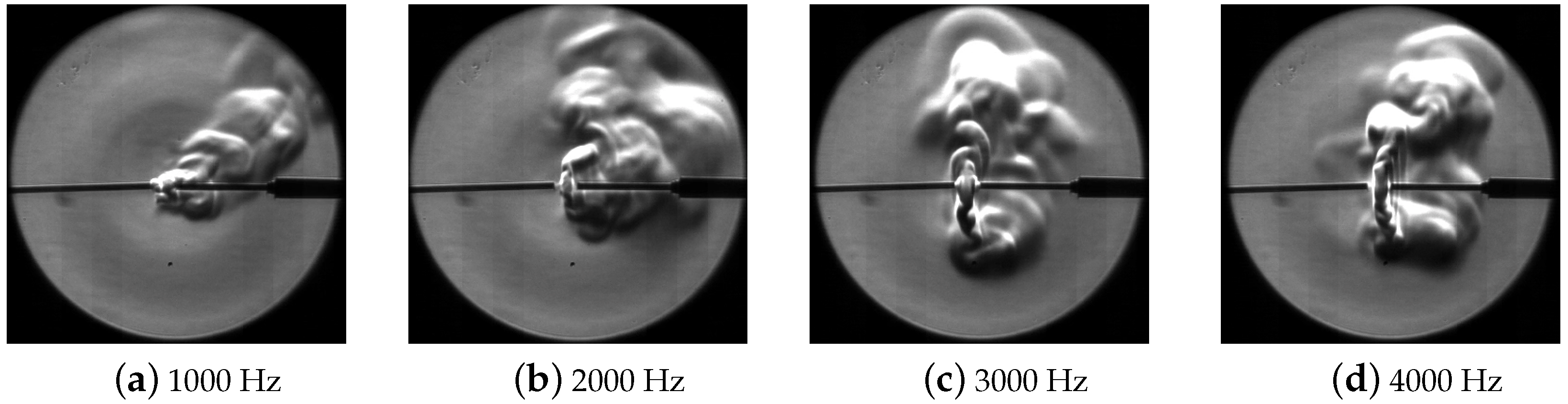
4. Properties of Plasma Discharge

Plasma, which is the forth state of the matter, provides unprecedented opportunity for combustion and flow control, owing to its unique capability in producing actice species, adding local energy, and modifying the gas properties. In general, when the plasma flow control and plasma-assisted combustion are talked about, their active species production, energy addition, and velocity perturbation are mainly considered. In the Rijke tube, a strong thermoacoustic coupling exists, so the acoustic effects of plasma may make a difference. In determining the effects of the plasma, besides the measurement of electrical characteristics, their velocity effects, and thermal effects, their pressure perturbation measurement was also performed. Regarding the electrical characteristics of this discharge device, the measurement results are shown in the following three figures. The current waveform can almost stay the same at different discharge repetition rates, as seen in Figure 3a, which proves that this discharge device can output a stable driving. Then, energy per pulse and the average power were calculated and presented in Figure 3b. The energy per pulse decreased, but the average power increased when the repetition frequency was changed. Although the averaged power of the discharge is about the order of tens of watts, which is much smaller compared to heating power (∼kW), it is clear from Figure 4 that its instantaneous power was so high that its thermal effect on the inlet stream should not be ignored.
Yvonne Sutton [35] studied the plasma acoustic in her PHD work, and it was revealed that the sound pressure level increases when the electrode spacing becomes larger. Here, we searched for a suitable electrode spacing and kept it constant. In our experiment, electrodes were set at the inlet of the Rijke tube so that the microphone needed to be placed inside the tube during the measurement, and the acoustic perturbation of the discharge propagating along the tube was obtained. The typical pressure perturbation waveforms at different discharge frequencies were measured, analyzed using fast Fourier transform, and compared, and the results are shown in Figure 5. It can be seen that (1) the amplitude of the pressure perturbation did not vary significantly with the discharge frequency; (2) after the FFT analysis, the oscillations of higher harmonic frequencies were excited; and (3) the amplitudes at a high frequency band of 4000 Hz discharge were much bigger than others. Actually, we think that its acoustic characteristics have a strong relationship with the plasma arc stability itself because the arc might go to an instable state, with the discharge frequency increasing.
Some frames (images after 500 pulses) of schlieren videos are presented in Figure 6, which showed their thermal effects but did not provide any quantitative information. The little velocity perturbation of discharge plasma was simply observed visually in a chambre filled with somke, which could be ignored when compared with the flow velocity in Rijke tube. These two effects need to be measured with more accurate means, but this is not possible under our current experimental conditions.

5. Results and Analysis

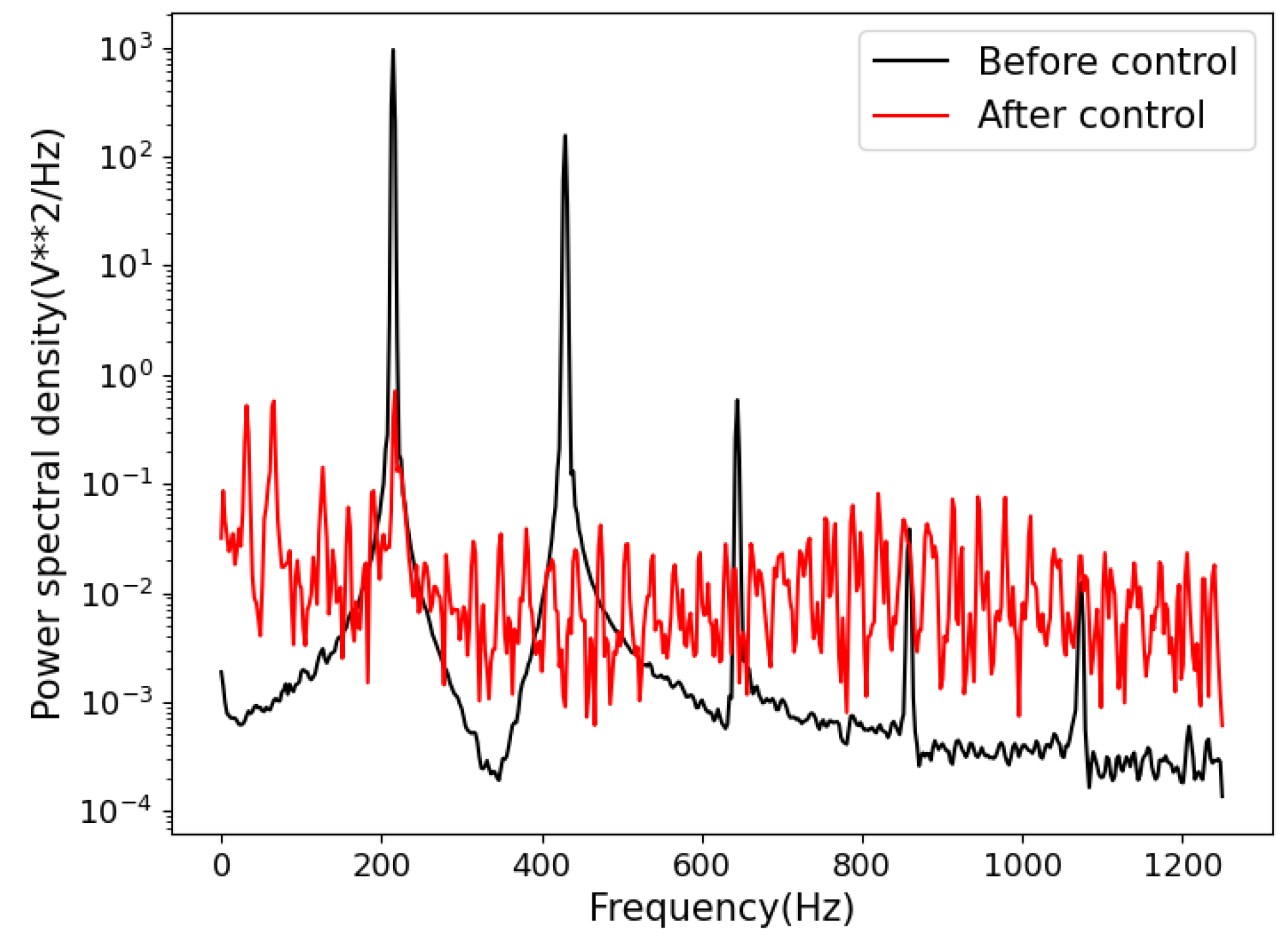
5.1. Control Results

Experiments were performed to see if the plasma could affect the THA oscillations. Some of the pressure data are shown in Figure 7, whose heating power used about 1.37 kW (analogue display 550). When the EM heating device was starting up, strong thermoacoustic oscillations were instantly generated in the Rijke tube. The saturated amplitude of pressure fluctuation detected was about 120 Pa . Several seconds after opening the heating device, the discharge plasma with different operating frequencies was applied. From (a), (b) in Figure 7, discharge with low-repetition frequencies, in other words, discharge with low average power, could not supress THA oscillations in the Rijke tube. Only the discharge frequency (average power) was high enough; the THA oscillations could be mitigated and would not re-occur in a certain period. The following could be inferred: (1) the discharge plasma can suppress THA oscillations in a Rijke tube; (2) for a defined case of THA oscillation, discharge with sufficiently high frequency or high average power is needed; and (3) the effectiveness of discharge depends more on its average power.
The results of all the experimental groups (variable heating power) are represented in the Figure 8. The time it took to suppress THA oscillations at different discharge frequencies was recorded as a judgment of effectiveness. The symbols on the grid nodes represent the success or failure of this experiment, and the points outside the grid nodes represent the actual time spent of the successful control. It is clearer: (1) only if the discharge were applied with sufficient high-repetition frequency and enough operation time could it mitigate THA oscillations in the Rijke tube; (2) with the heating power increased, the discharge frequency needed to suppress THA oscillations became higher; and (3) the dicharge with higher repetition frequency needed less time to suppress the oscillations, i.e., to be more effective.

5.2. Acoustic Characterisctics in the Rijke Tube during Plasma Operating

In order to know what happend to the thermoacoustic oscillations when plasma were applied, the pressure signals were analyzed further. FFT and power spectral density (PSD) analysis were firstly used to see their spectrum characteristics. From the FFT result in Figure 9 and the PSD result in Figure 10, it is clear that oscillations lost their defined frequencies, but chaos oscillations were without particular frequencies instead. From the result of short-time FFT analysis shown in Figure 11, the pressure field in the Rijke tube showed a strong nonlinearity during the discharge. It is thought that the chaos, the non-linearity, and the non-resonant oscillations introduced huge acoustic dissipation. Because of the higher dissipation of the high-harmonic oscillations and the nonlinear oscillations, the dissipation of sound energy was bigger than its gain, which decided that the amplitude of oscillation would decrease.
After the above analysis, although the plasma discharge could increase the dissipation of the sound energy in THA oscillations, the oscillations could still be re-established after the end of the plasma discharge if the THA coupling was not broken. However, the re-occurrence of THA oscillations was not observed in the experiments. Regarding this point, the average temperature at the upstream of the heat source was simply measured by thermocouple. The average temperature had a increase during the discharge. Considering the properties of discharge plasma introduced in Section 4, it is believed that their thermal effect is the reason. The plasma arc instantaneously heated the inlet gas, which affected the heat transfer between the heat source and the mainstream and broke the thermoacoustic coupling.

6. Discussion and Conclusions

In the present work, the Rijke tubes using the induction heating tungsten mesh as a heat source with active control were built. The electrical, acoustic, and dynamical characteristics of the discharge plasma actuators were experimentally measured at room temperature and pressure. It was demonstrated in experiments that the discharge plasma can suppress THA oscillations in a Rijke tube. In experiments, it is found that discharge with higher repetition frequency (higher average power) is required for suppressing THA oscillations with higher heating power. The FFT analysis of pressure fluctuation shows that when plasma is operating, the amplitude of the higher harmonic frequencies increases and the pressure shows non-linearity. The plasma suppression of THA oscillations may be due to the following two factors: (1) transferring energy from major eigenmodes to higher harmonic and other incoherent frequencies thann the acoustic loss increased; (2) abruptly heating the inlet airflow influence the heat exchange and the thermo-acoustic coupling.
In this study using microsecond pulse discharge plasma to suppress THA oscillations, we found that the thermal effects of plasma of both of their pressure perturbations make a difference. As promising actuators for active control, the discharge plasma actuators can be applied in high-temperature and high-pressure environments. Moreover, plasma can assist burning in the combustor after ingenious design. In the future, the use of different distributions of discharge electrodes, combining multiple plasma actuators, higher repetition rate discharge devices (nanosecond repetitively pulsed), more theoretical work, and experiments with more accurate diagnosis in real combustors, may be necessary.

Author Contributions

Writing—original draft preparation, Investigation, J.D.; Writing—review and editing, Funding acquisition, T.L.; Software, J.W.; Investigation, C.G. All authors have read and agreed to the published version of the manuscript.

Funding

This research was funded by State Key Laboratory of High Temperature Gas Dynamics, funding No.2021KF05.

Data Availability Statement

Not applicable.

Conflicts of Interest

The authors declare no conflict of interest.

References

  1. Hawthorne, W.R. Theory of Combustion Instability in Liquid Propellant Rocket Motors. J. Fluid Mech. 1957, 2, 100–104. [Google Scholar] [CrossRef]
  2. Hegde, U.; Reuter, D.; Zinn, B.; Daniel, B. Fluid mechanically coupled combustion instabilities in ramjet combustors. In Proceedings of the 25th AIAA Aerospace Sciences Meeting, Reno, NV, USA, 24–26 March 1987; p. 0216. [Google Scholar] [CrossRef]
  3. Langhorne, P.J. Reheat buzz: An acoustically coupled combustion instability. Part 1. Experiment. J. Fluid Mech. 1988, 193, 417–443. [Google Scholar] [CrossRef]
  4. Mongia, H.C.; Held, T.J.; Hsiao, G.C.; Pandalai, R.P. Challenges and Progress in Controlling Dynamics in Gas Turbine Combustors. J. Propuls. Power 2003, 19, 822–829. [Google Scholar] [CrossRef]
  5. Koshigoe, S.; Komatsuzaki, T.; Yang, V. Adaptive Control of Combustion Instability with On-Line System Identification. J. Propuls. Power 1999, 15, 383–389. [Google Scholar] [CrossRef]
  6. Giuliani, F.; Gajan, P.; Diers, O.; Ledoux, M. Influence of pulsed entries on a spray generated by an air-blast injection device: An experimental analysis on combustion instability processes in aeroengines. Proc. Combust. Inst. 2002, 29, 91–98. [Google Scholar] [CrossRef]
  7. Raun, R.; Beckstead, M.; Finlinson, J.; Brooks, K. Review of Rijke tubes, Rijke burners and related devices. Prog. Energy Combust. Sci. 1993, 19, 313–364. [Google Scholar] [CrossRef]
  8. Rayleigh, J.S.W. The Theory of Sound, 2nd ed.; Dover Publications: New York, NY, USA, 1945. [Google Scholar]
  9. Culick, F. Nonlinear behavior of acoustic waves in combustion chambers—I. Acta Astronaut. 1976, 3, 715–734. [Google Scholar] [CrossRef]
  10. Zhao, D.; Li, X. A review of acoustic dampers applied to combustion chambers in aerospace industry. Prog. Aerosp. Sci. 2015, 74, 114–130. [Google Scholar] [CrossRef]
  11. Zhao, D.; Lu, Z.; Zhao, H.; Li, X.; Wang, B.; Liu, P. A review of active control approaches in stabilizing combustion systems in aerospace industry. Prog. Aerosp. Sci. 2018, 97, 35–60. [Google Scholar] [CrossRef]
  12. Richards, G.A.; Straub, D.L.; Robey, E.H. Passive Control of Combustion Dynamics in Stationary Gas Turbines. J. Propuls. Power 2003, 19, 795–810. [Google Scholar] [CrossRef]
  13. Park, I.S.; Sohn, C.H. Nonlinear acoustic damping induced by a half-wave resonator in an acoustic chamber. Aerosp. Sci. Technol. 2010, 14, 442–450. [Google Scholar] [CrossRef]
  14. Sohn, C.H.; Park, J.H. A comparative study on acoustic damping induced by half-wave, quarter-wave, and Helmholtz resonators. Aerosp. Sci. Technol. 2011, 15, 606–614. [Google Scholar] [CrossRef]
  15. Zhao, D.; Morgans, A.S.; Dowling, A.P. Tuned Passive Control of Acoustic Damping of Perforated Liners. AIAA J. 2011, 49, 725–734. [Google Scholar] [CrossRef]
  16. Zhao, D.; Morgans, A. Tuned passive control of combustion instabilities using multiple Helmholtz resonators. J. Sound Vib. 2009, 320, 744–757. [Google Scholar] [CrossRef] [Green Version]
  17. Olgac, N.; Zalluhoglu, U.; Kammer, A.S. A New Perspective in Designing Delayed Feedback Control for Thermo-Acoustic Instabilities (TAI). Combust. Sci. Technol. 2015, 187, 697–720. [Google Scholar] [CrossRef]
  18. Zalluhoglu, U.; Kammer, A.; Olgac, N. Delayed Feedback Control Laws for Rijke Tube Thermoacoustic Instability, Synthesis, and Experimental Validation. IEEE Trans. Control. Syst. Technol. 2016, 24, 1861–1868. [Google Scholar] [CrossRef]
  19. Deshmukh, N.N.; Sharma, S. Suppression of thermo-acoustic instability using air injection in horizontal Rijke tube. J. Energy Inst. 2017, 90, 485–495. [Google Scholar] [CrossRef]
  20. Niederberger, A.; Fritsche, D.; Boulouchos, K.; Guzzella, L. Thermoacoustic instability suppression by gain-delay and Hinf controllers designed for secondary fuel injection. IEEE Trans. Control. Syst. Technol. 2009, 17, 1028–1042. [Google Scholar] [CrossRef]
  21. Gutmark, E.; Wilson, K.; Yu, K.; Smith, R.; Schadow, K. Active control of a liquid fuel combustor/incinerator using pulsed injection. In Proceedings of the 33rd Aerospace Sciences Meeting and Exhibit, Reno, NV, USA, 9–12 January 1995. Chapter 95-0809. [Google Scholar] [CrossRef]
  22. D’Entremont, J.; Gejji, R.M.; Venkatesh, P.; Bane, S.P. Plasma Control of Combustion Instability in a Lean Direct Injection Gas Turbine Combustor. In Proceedings of the 52nd Aerospace Sciences Meeting, National Harbor, MD, USA, 13–17 January 2014; pp. 13–17. [Google Scholar] [CrossRef]
  23. Starikovskiy, A.; Aleksandrov, N. Plasma-assisted ignition and combustion. Prog. Energy Combust. Sci. 2013, 39, 61–110. [Google Scholar] [CrossRef] [Green Version]
  24. Ju, Y.; Sun, W. Plasma assisted combustion: Dynamics and chemistry. Prog. Energy Combust. Sci. 2015, 48, 21–83. [Google Scholar] [CrossRef]
  25. Ju, Y.; Sun, W. Plasma assisted combustion: Progress, challenges, and opportunities. Combust. Flame 2015, 162. [Google Scholar] [CrossRef]
  26. Lacoste, D.A.; Moeck, J.P.; Durox, D.; Laux, C.O.; Schuller, T. Effect of Nanosecond Repetitively Pulsed Discharges on the Dynamics of a Swirl-Stabilized Lean Premixed Flame. J. Eng. Gas Turbines Power 2013, 135, 101501. [Google Scholar] [CrossRef]
  27. Zhou, S.; Nie, W.; Tian, Y. High frequency combustion instability control by discharge plasma in a model rocket engine combustor. Acta Astronaut. 2021, 179, 391–406. [Google Scholar] [CrossRef]
  28. Guo, C. Research on Plasma Assisted Suppression of Combustion Oscillation. Master’s Thesis, Harbin Institute of Technology, Harbin, China, 2019. [Google Scholar]
  29. Zhang, M.; Li, J.; Cheng, W.; Li, T. Active control of thermoacoustic instability using microsecond plasma discharge. J. Appl. Phys. 2020, 127, 033301. [Google Scholar] [CrossRef]
  30. Matveev, K. Energy consideration of the nonlinear effects in a Rijke tube. J. Fluids Struct. 2003, 18, 783–794. [Google Scholar] [CrossRef]
  31. Zhang, Y.; Huang, L. Electroacoustic control of Rijke tube instability. J. Sound Vib. 2017, 409, 131–144. [Google Scholar] [CrossRef]
  32. Howe, M.S. Acoustics of Fluid-Structure Interactions; Cambridge Monographs on Mechanics; Cambridge University Press: Cambridge, UK, 1998. [Google Scholar] [CrossRef]
  33. Poinsot, T.; Candel, S. A Nonlinear Model for Ducted Flame Combustion Instabilities. Combust. Sci. Technol. 1988, 61, 121–153. [Google Scholar] [CrossRef]
  34. Harrje, D.J.; Reardon, F.H.E. Liquid Propellant Rocket Combustion Instability; Report No. NASA SP-194; NASA: Washington, DC, USA, 1972.
  35. Sutton, Y. Electro-Acoustic Coupling in a Plasma Gas. Ph.D. Thesis, The Open University, Milton Keynes, UK, 2012. [Google Scholar]
Figure 1. Schematic diagram of acoustic field in a Rijke tube.
Aerospace 09 00836 g001
Figure 2. The Rijke tube (THA oscillation system).
Aerospace 09 00836 g002
Figure 3. (a) Current waveform; (b) average power and energy per pulse at different discharge frequencies.
Aerospace 09 00836 g003
Figure 4. Discharge waveform.
Aerospace 09 00836 g004
Figure 5. (a) Pressure perturbation waveform and (b) FFT results at different discharge frequencies.
Aerospace 09 00836 g005
Figure 6. High-speed schlieren imaging of PDD at differet repetition rate.
Aerospace 09 00836 g006
Figure 7. Pressure data when discharge was applied at different repetition rates (heating power: 1.37 kW).
Aerospace 09 00836 g007
Figure 8. Experimental groups at different heating powers (every grid nodes represent an actual work setting , e.g., (3000 Hz, 10 s) means that the discharge device worked at 3000 Hz repetition rate for 10 s).
Aerospace 09 00836 g008
Figure 9. THA oscillation with and without discharge.
Aerospace 09 00836 g009
Figure 10. Power spectral density of pressure signal with and without discharge.
Aerospace 09 00836 g010
Figure 11. STFT results of the pressure signal in Figure 7e (5000 Hz discharge at 1.44 kW heating power).
Aerospace 09 00836 g011
Publisher’s Note: MDPI stays neutral with regard to jurisdictional claims in published maps and institutional affiliations.

