1. Introduction
Launch vehicles, which are typically large in size and have high slenderness ratios, play an essential role in the history of human spaceflight and the exploration of the universe. With the development of modern science and technology, the tasks to be completed by launch vehicles have gradually increased. The shape of the launch vehicles is also elongated, which increases their slenderness ratio. The increasing slenderness ratio lowers the natural frequency of the rocket bending modes. When these encroach upon the frequency range of the rocket’s bandwidth, it becomes difficult to impose control. Liquid propellants, which are typically used in launch vehicles of this size, further exacerbated this issue due to the propellent sway caused by them. Taken together, the high slenderness ratio and propellent present a tough challenge for an attitude control system. For a rocket with a high slenderness ratio, its low-order elastic vibration is easy to be coupled with the vibration of the spacecraft itself, and the sloshing of the liquid propellant is hard to suppress, which makes control more difficult to achieve. To better complete the missions, the attitude control problems faced by the launch vehicle with a high slenderness ratio and multi-propellant storage tanks have become a hotspot of research [
1,
2].
In recent years, various novel control methods have emerged to suppress elastic vibration. In [
3], a composite controller with a hierarchical structure is designed to suppress elastic vibration. It combines disturbance observer-based control with PD control. However, the speed of convergence needs to be improved. To prevent the transfer of energy from the rocket casing to the detector stage, several stages of traditional vibration damping systems are used to mitigate the impact of elastic vibration on attitude control [
4]. In [
5], a Coulomb element and Jenkins element are applied as the vibration reduction mechanism of the joint to enhance energy dissipation in the friction damper. These methods optimize the structure of the vibration damping system for the traditional rocket, which reduces the payload of the launch vehicle despite a good elastic vibration damping effect produced by them. In [
6], the pole configuration method is used to design the adaptive attitude control law of the elastic launch vehicle to suppress vibrations. An improved adaptive augmented control method was studied to suppress the instability of rocket control with a high length and slenderness ratio. By extracting and processing the high-order signals in tracking errors, the gain is given to the controller according to the adaptive gain regulation law [
7]. This proves to be effective for the attitude control of large, elongated rockets. In [
8], a closed-loop feedback control system was designed by introducing a PID controller to address the elastic vibration of a flexible rocket. For different control objects, however, it was difficult to set parameters. Considering that H2 control is often adopted to deal with transient performance and H∞ control guarantees robust stability in the presence of parameter uncertainties and external disturbances, an improved hybrid H2/H∞ control strategy was proposed for the attitude stabilization and vibration suppression of flexible spacecraft under pole assignment constraints [
9]. However, these control methods based on the design of flexible spacecraft may not perform well in robustness to the multi-order elastic vibrations (especially low-order elastic vibrations) that occur in those launch vehicles with high slenderness ratios.
The sliding mode of the variable structure control system shows strong robustness to perturbation and external disturbances. The attitude control system design based on the sliding mode variable structure theory has been widely adopted in the research of vibration suppression [
10,
11,
12]. An adaptive integral second-order sliding mode controller with excellent robust performance is used for attitude control [
13]. A differentiator is used to obtain the higher order derivatives of sliding mode surfaces, and a higher order sliding mode variable structure controller is designed to suppress elastic vibration [
14]. A robust higher order sliding mode control method is designed in [
15]. In [
16], a launch vehicle control method based on the sliding mode control and observation technology is adopted. However, all observations may be highly affected by various uncertainties, and a generalized stochastic perturbation technique is proposed to obtain numerical solutions to the stochastic perturbation dynamics equations [
17,
18]. These studies ignore the impact of propellant sloshing on the attitude of large-size launch vehicles.
Currently, most large-sized multi-stage launch vehicles make use of liquid propellants that slosh around during the flight. If not suppressed promptly, it may cause damage to the system and lead to attitude divergence. However, there are still a few studies on the suppression of fuel sloshing at present. In recent years, the attitude control methods considering liquid fuel sloshing for satellites and spacecraft have been widely studied [
19,
20]. However, they are not suitable for those launch vehicles with high slenderness ratios. Therefore, the attitude stability control for the elastic vibration and propellant sloshing of the launch vehicle with a high slenderness ratio remains a challenge, and is the focus of this study.
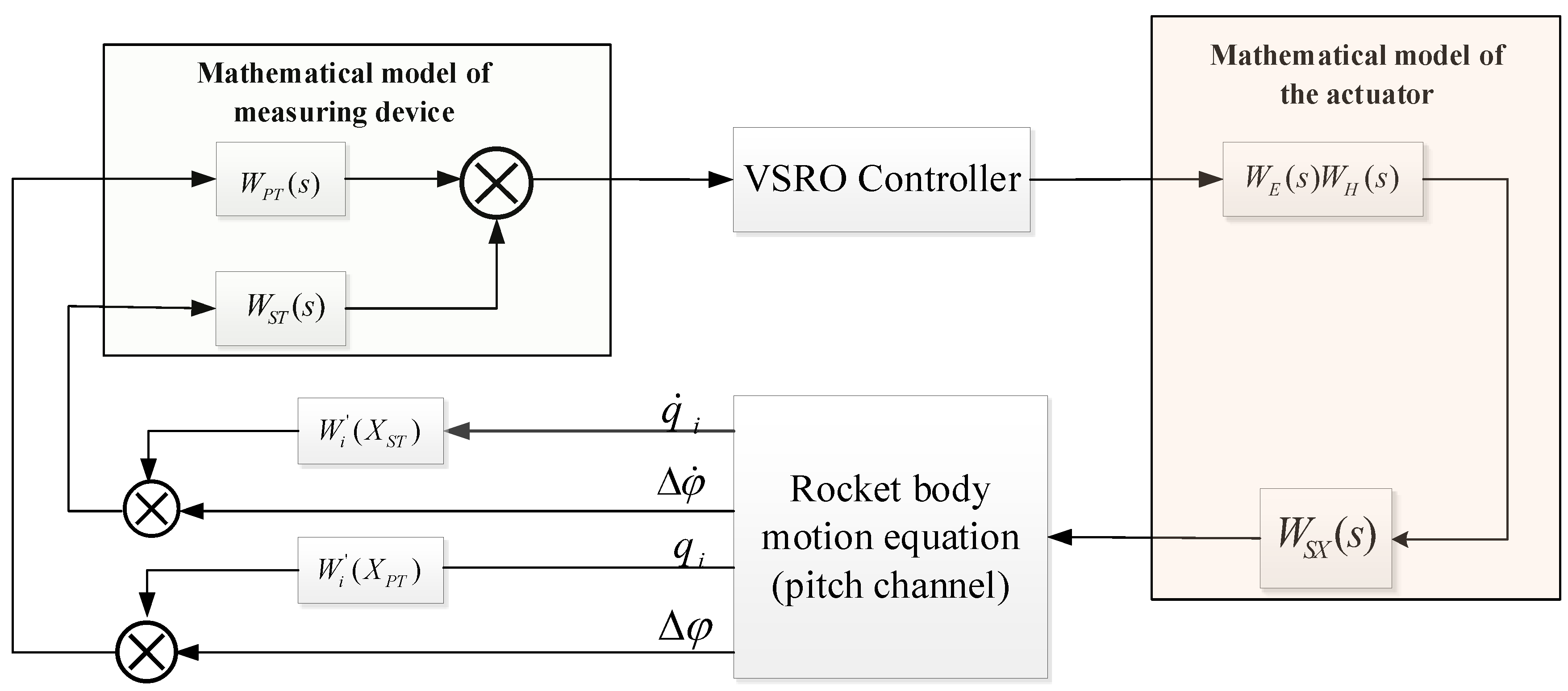
To the best of our knowledge, this is the first reported work to realize the rocket’s attitude stabilization considering the elastic vibration and fuel sloshing simultaneously. The impact of elastic vibration, propellant sloshing, and elastic vibration on the measurement of rocket attitude angle and angular velocity are carefully considered in this paper. The idea of combining a robust observer and variable structure controller is adopted in an innovative way to control the attitude of launch vehicles. Firstly, a variable-gain robust observer is applied to reconstruct the attitude angle, angular rate, and state variables of the rocket after consideration is given to the effect of elastic vibrations on the measurement of attitude and angular velocity. The comprehensive influence exerted by each order of elastic vibration on attitude is transformed into an additional attitude angle and angular velocity with the characteristics of rocket attitude (i.e., the additional attitude that can be controlled by a rocket attitude control loop). Secondly, a variable structure controller with good robust performance is designed according to the attitude control equation. The reconstructed attitude angle and angular velocity with additional attitude are used as the controller inputs, which stabilizes the attitude characteristics of the rocket. Then, the stabilization of the rocket attitude under the action of the controller is demonstrated, and the conclusion is drawn through theoretical derivate ion that the propellant sloshing will be stabilized with attitude stability. Finally, the simulation results show that the attitude obtained by the robust observer, as designed in this paper, is suitable for reconstructing the system attitude angle. The reconstructed attitude produces a more significant filtering effect compared to the rocket attitude before reconstruction, which is more conducive to imposing control. This allows the variable structure controller to stabilize the elastic vibration (especially the low-order vibration) on the rocket. The outcome of stabilization is better than the single variable structure controller in literature [
13] with or without external interference. Furthermore, it achieves an excellent anti-sloshing effect simultaneously. The control flow of the controller is shown in
Figure 1.
3. Design of Variable Structure Controller Based on Variable-Gain Robust Observer
3.1. Design of the Variable-Gain Robust Observer
The variable-gain robust observer has the characteristic of low-pass filtering for external disturbances and can stabilize the amplitude of high order elastic vibration modes. For the filtered low order elastic vibration modes, if the observer is added after the attitude-sensitive output, the response of the observer to the low order elastic vibration part will be the response to the average energy of each order mode.
Considering that the attitude control system in rocket control has the following forms:
where
is the attitude state matrix,
is the control matrix,
is the set output matrix, where
.
is the attitude vector,
is the output signal vector,
is the control vector,
represents the sum of uncertain parts of the system. Each matrix has a corresponding dimension,
,
,
.
Introducing a nonsingular transformation
,
Then Equation (13) can be transformed into
Expand Equation (15) as
where
,
,
.
For the transformed dynamic equation, the following observer is designed as
Following [
24], let (20) be specified with the components
where
,
in (19) are the coefficients of the characteristic equation
,
,
are variable gains in (21). Then the error dynamics are governed by
Remark 2. In order to guarantee the stability of the designed observer, the nonsingular transformation
taken should ensure thatis stable.
Theorem 1. According to [
25]
, under the condition that the observer variable-gain is chosen correctly, the error motion (22) is stable convergence. In order to suppress the chattering caused by uncertainty, the boundary layer is introduced for continuity,
is designed as
where
is the solution of the Lyapunov equation
,
is a symmetric positive definite matrix. The parameter
meets the Lyapunov stability condition of the following error equation,
.
The observer has been designed, it is expressed in the following common forms
Introducing
,
, (24) can be further simplified to
The observer proposed introduces variable structure control and variable gains to adapt to the perturbation and disturbances of the system, which is a robust observer.
3.2. Design of Sliding Mode Controller
After the reconstructed attitude angle and angular velocity of the launch vehicle are obtained by the variable-gain robust observer, the variable structure control law is designed. The sliding surface is defined as follows,
where
,
are the reconstructed attitude angle and angular velocity.
Rewrite as
where
is the reconstructed state vector.
The motion equation of the sliding mode of the system is
where
is the interference. In the ideal case, when the interference
is
, the attitude motion will converge to zero.
According to the sliding mode control design criteria,
, as
The equivalent control can be solved as
The sliding mode equation is
The reaching law is chosen as
where
and
are constants.
To reduce chattering, the boundary layer method is introduced to the continuum of the reaching law, and the continuous control is expressed as
where
is a small constant,
,
,
are constants to be designed.
So far, the controller design is completed.
3.3. Principle of Propellant Sloshing Stabilization
The following takes the
fuel tank as an example to demonstrate that the controller designed in this paper can stabilize the propellant sloshing. Considering the center of mass motion
,
, and the angular acceleration of nozzle swing
as disturbance quantities. Then, the attitude motion Equations (1)–(3)are simplified as follows:
where
,
.
is the reaction moment of the rudder inertia force. The rest notations are shown in
Section 2.
The attitude motion equation can be described in the form of a state equation. The state vector of the system is defined as
where,
,
.
The attitude motion Equations (34) and (35) are expressed in the form of state equations as
where
,
,
,
,
,
,
,
.
In the Equation (37), SUBSYSTEM 1 represents the attitude motion Equation (34) and SUBSYSTEM 2 represents the propellant sloshing Equation (35). It can be seen that the fuel sloshing influences the stability of the system by affecting the attitude angle motion of the rigid body. According to the robust performance theory of variable structure, SUBSYSTEM 1 can stabilize the attitude angle motion through variable structure control, and there will be no steady-state error when the control torque is large enough to completely suppress the disturbances. For SUBSYSTEM 2, since and , it is easy to know that is a stable matrix, so SUBSYSTEM 2 is internally stable. When the attitude motion converges, the control variable is also stabilized, that is, the engine declination angle is stabilized at a certain value, then the propellant sloshing will also converge to a certain position.
This section mainly describes the principle of propellant sloshing stabilization. In order to facilitate analysis, the following assumption can be made.
Assumption 2: The designed variable structure controller makes the attitude angle of SUBSYSTEM 1 stabilization.
To study the stability of SUBSYSTEM 2
, we consider the characteristic equation as
And the and are small quantities in the matrix , then .
Substituting the above quantities into the characteristic Equation (38), the two eigenvalues have negative real parts, so is a stable matrix.
According to the stability theory of differential equations [
26], the SUBSYSTEM 2 is asymptotically stable.
3.4. Principle of Observer to Suppress Elastic Vibration
According to (25), the dynamic equation of the constructed robust observer as
where
,
,
, The remaining vectors and matrices have corresponding dimensions.
The elastic output , are converted to and through the designed observer, respectively.
Taking the
mode as an example, the control
is treated as interference.
where,
.
The state equation of the augmented system can be expressed as follows
When the variable structure controller stabilizes the system attitude, the sliding mode is defined as
where
. The motion on the switching line meets
,
, and the equivalent control is calculated by the equivalent control method as follows:
Substituting (43) into (41), the closed-loop equivalent system equation after the system enters the sliding mode as
where
,
,
,
.
In fact, since the magnitude of
and
is
,
is considered
. Therefore, if the designed gain matrix meets the following two conditions,
It can make the equivalent system stable.
The variable structure control can be obtained according to the exponential reaching law, as
where
.
Further sorting,
When
,
in the control law (49) can be ignored, that is
Therefore, for the elastic subsystem and the attitude subsystem there is a unified variable structure control law to make the sliding surface reachable.
4. Simulation Results and Analysis
In this paper, by taking a certain type of launch vehicle as the research object, a dynamic model of the rocket pitch channel is constructed, including elastic vibration, liquid sloshing, and external disturbances. The sliding mode variable structure control method based on a variable-gain robust observer, as designed in this paper, is compared with the variable structure control method without an observer as proposed in [
13].
The initial pitch angle deviation is
, the simulation step length is set to 0.001 s, and the simulation time is set to 20 s. A 4th-order Runge-Kutta program with a fixed step size is used to numerically solve the differential equations. The design parameters of the sliding mode controller are shown in
Table 1. The elastic vibration parameters and liquid fuel sloshing parameters are shown in
Table 2 And
Table 3, respectively. The system matrix
, the observation matrix
, and the transformation matrix
. In order to validate the proposed controller, numerical simulation is performed in three parts. Section I and Section II relate to the simulation of elastic vibration suppression performance with and without external interference, while Section III deals with the simulation of liquid sloshing stabilization.
The initial values of seven orders of elastic vibration are selected as
. The initial values of four orders of liquid sloshing are selected as
. The gains
,
are chosen as in ([
25] Section V.B), respectively. When there are no other disturbances other than propellant sloshing and elastic vibration, the simulation results are obtained as shown in
Figure 3,
Figure 4,
Figure 5,
Figure 6,
Figure 7,
Figure 8,
Figure 9 and
Figure 10.
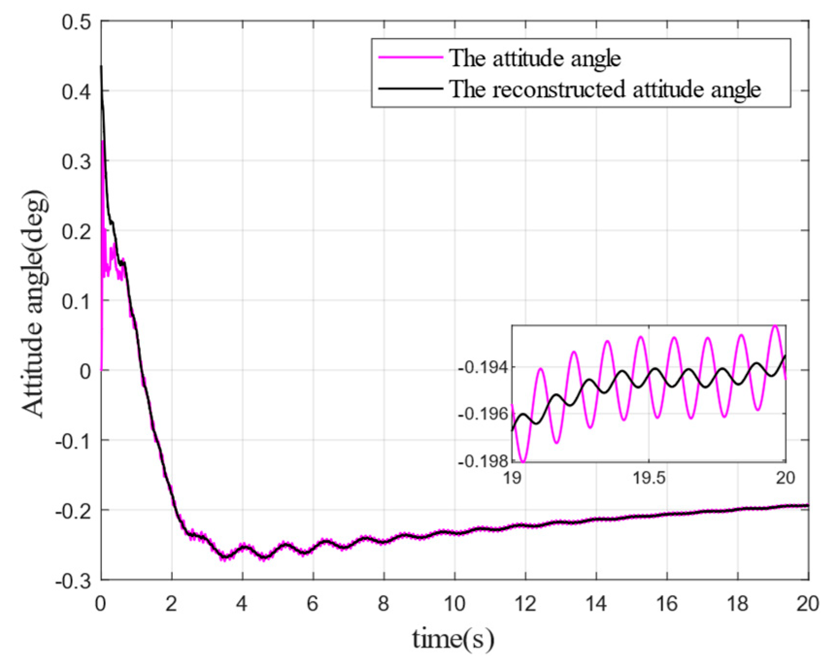
Figure 3 and
Figure 4 show the reconstruction effect of attitude angle and angular velocity, respectively. It can be seen that the reconstructed attitude angle and angular velocity produce a more significant filtering effect compared with those before reconstruction, and the curves become smoother. The attitude angle before reconstruction shows a minor oscillation at 1 s. Besides, after reconstruction through the designed observer, the attitude angle converges steadily. The filtering effect of the observer is much better in the attitude angular velocity. As can be seen from
Figure 3, the oscillation amplitude of the reconstructed attitude angular velocity is significantly reduced compared with before reconstruction, which indicates that the reconstruction of the disturbed attitude angle and angular velocity into new ones by the proposed observer can stabilize the rocket attitude more easily.
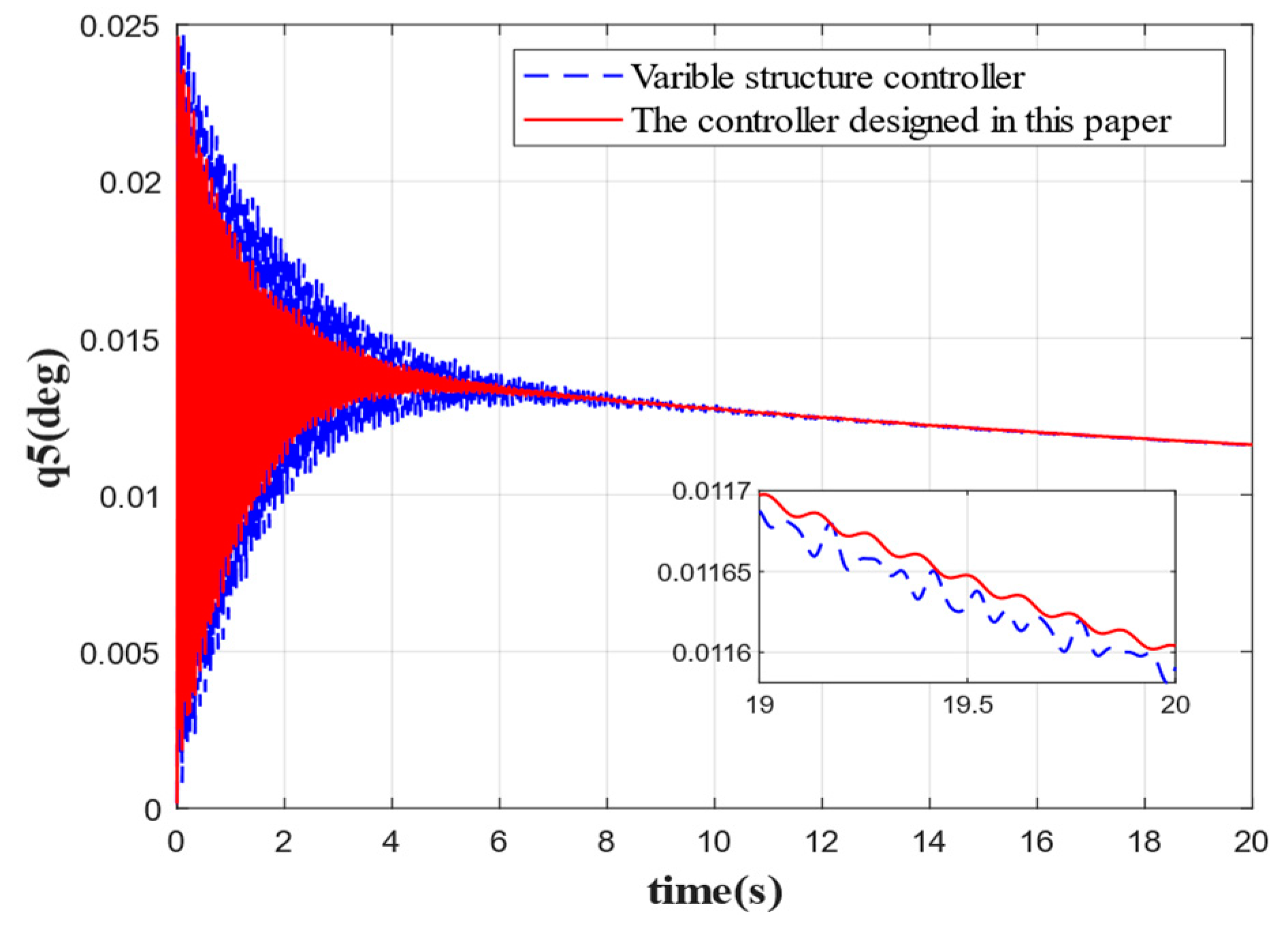
Figure 5,
Figure 6,
Figure 7,
Figure 8 and
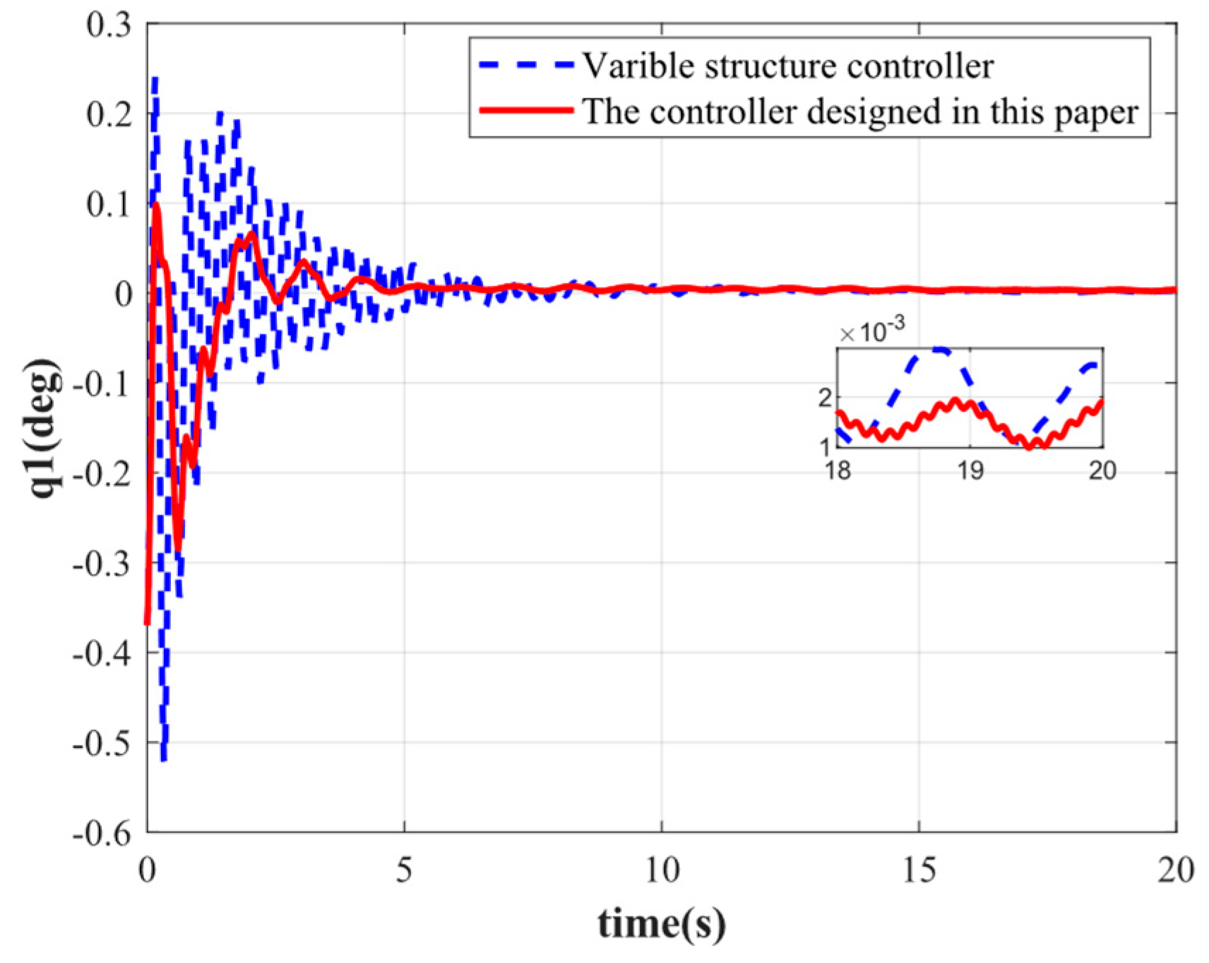
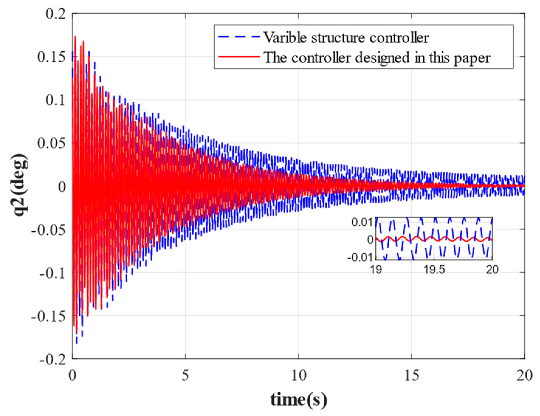
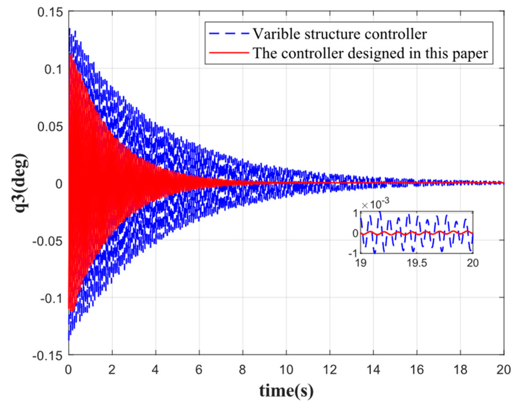
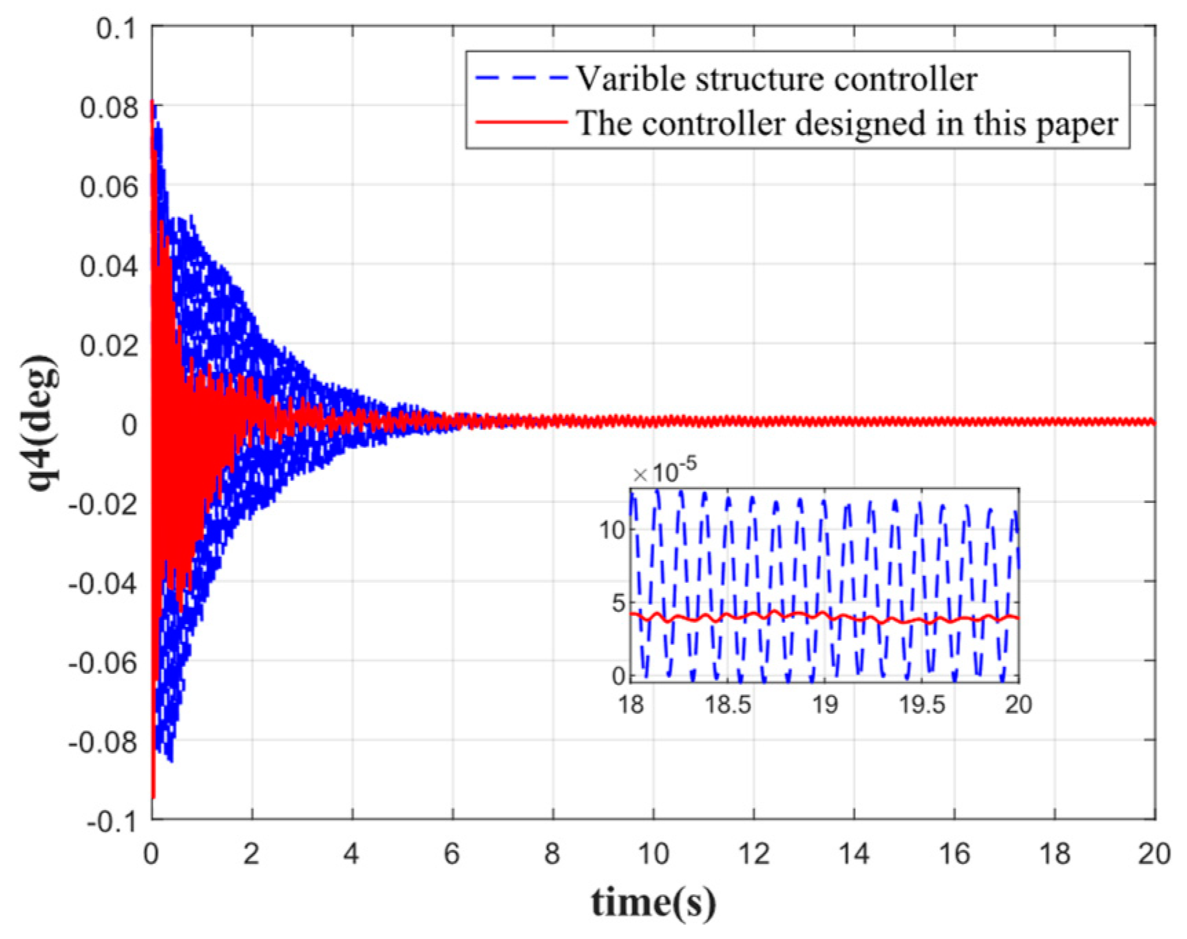
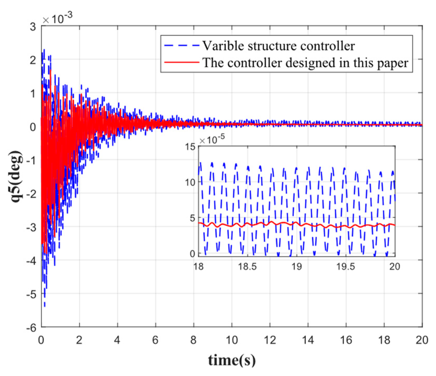
Figure 9 show the comparison of the suppression effect produced by each order of elastic vibration. It can be seen that when there are no disturbances other than propellant sloshing and elastic vibration during the stabilization of the rocket, the stabilization effect of the controller designed in this paper for each order of elastic vibration is better than that of the traditional variable structure control method intended for the stabilization of the rocket.
As shown in
Figure 5, the first-order elastic vibration converges faster when the elastic attitude angle and angular velocity are reconstructed by the variable-gain robust observer followed by attitude control. The first-order elastic vibration converges to 0 at 4 s. Compared with the traditional sliding mode variable structure control, the rapidity is improved by 5 s, the oscillation frequency is reduced by 50%, and the steady-state error is 0.0015 deg. By contrast, the steady-state error of the traditional variable structure control is 0.003 deg, which evidences that the controller designed in this paper achieves a good stabilization effect on low-order elastic vibration. Although the oscillation frequency of other orders of elastic vibration is not significantly reduced, the speed of convergence is substantially improved, and the convergence time is shortened by 5 s, 10 s, 6 s, and 2 s, respectively. By comparison, the oscillation amplitude is significantly reduced. It can be seen that the integrated approach combining state reconstruction with variable structure control produces a better suppression effect on elastic vibration for attitude stabilization, especially the low-order elastic vibration, which is significantly better than the traditional variable structure control method. In addition, the accuracy of control by the proposed method is also higher compared to the traditional control method.
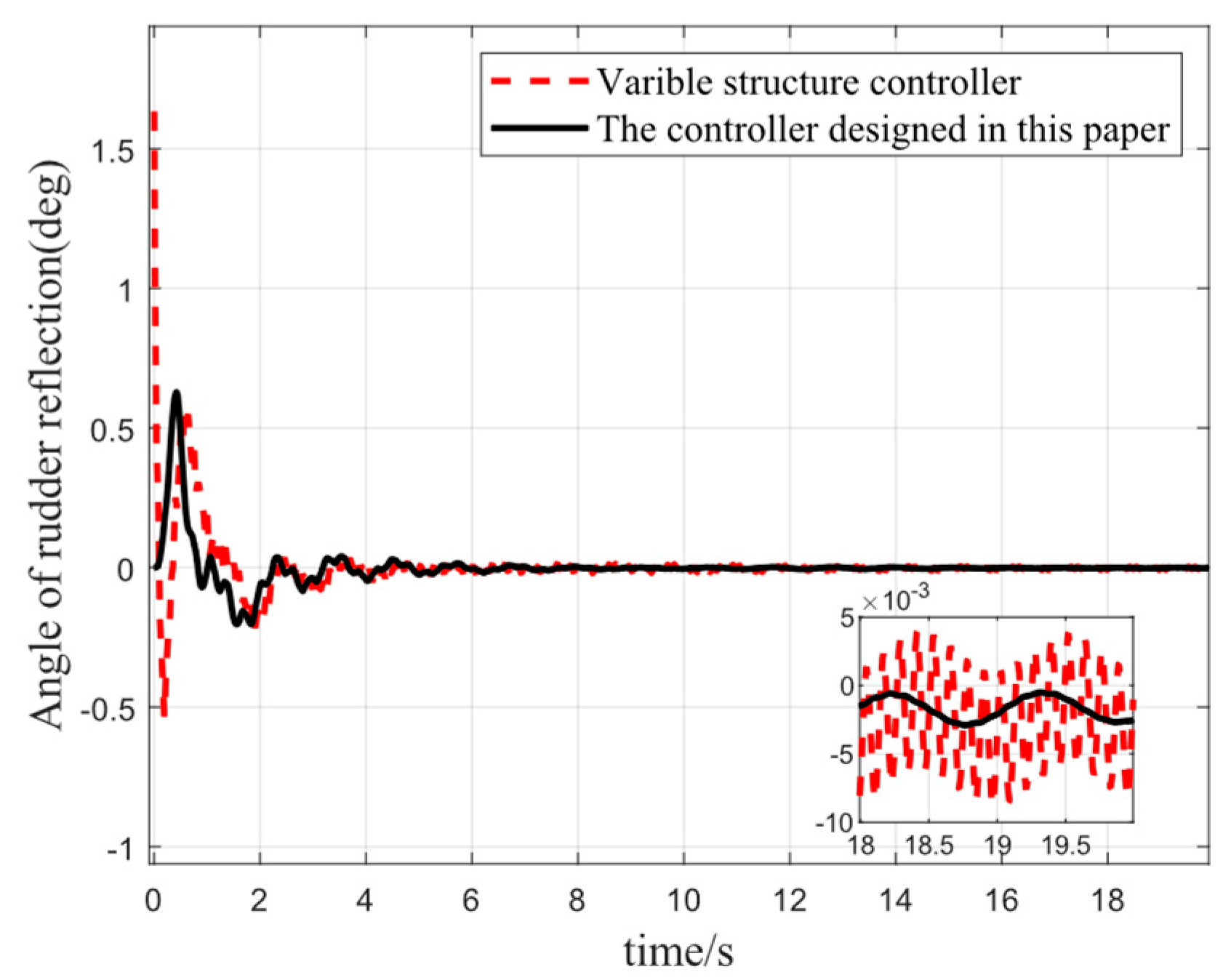
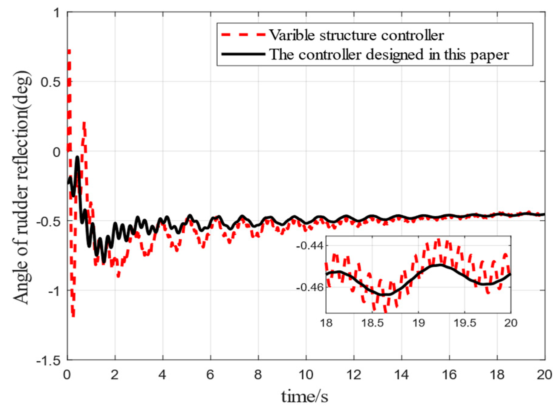
Figure 10 shows a comparison of the trend of rudder deflection angle variation trend during the process of rocker attitude stabilization. It can be seen that the maximum rudder deflection angle under the traditional variable structure control is 1.6 deg, while the maximum rudder deflection angle reached by using the method in this paper is only 0.6 deg. Compared with the traditional control method, the controller designed in this paper has less chattering and converges to the equilibrium position faster, which is attributable to the fact that the designed observer averages the energy of elastic vibration to the attitude angle and significantly mitigates the effect of elastic vibration.
Figure 11 and
Figure 12 show the reconstruction of the attitude angle and angular velocity by the variable-gain robust observer designed in this paper when external interference is taken into account.
When external interference is ignored, the observer converts the perturbation effect of elastic vibration on the attitude angle into an additional attitude angle, which makes the reconstructed curve much smoother than before reconstruction. Moreover, it can be seen from
Figure 12 that the filtering effect of the angular velocity is significantly improved after the introduction of external perturbation, which indicates that the designed observer has solid robustness and can be applied in scenarios with strong external interference. Due to the persistent effect of the external disturbance torque, neither the attitude angle nor the angular velocity converges to 0.
Figure 13,
Figure 14,
Figure 15,
Figure 16 and
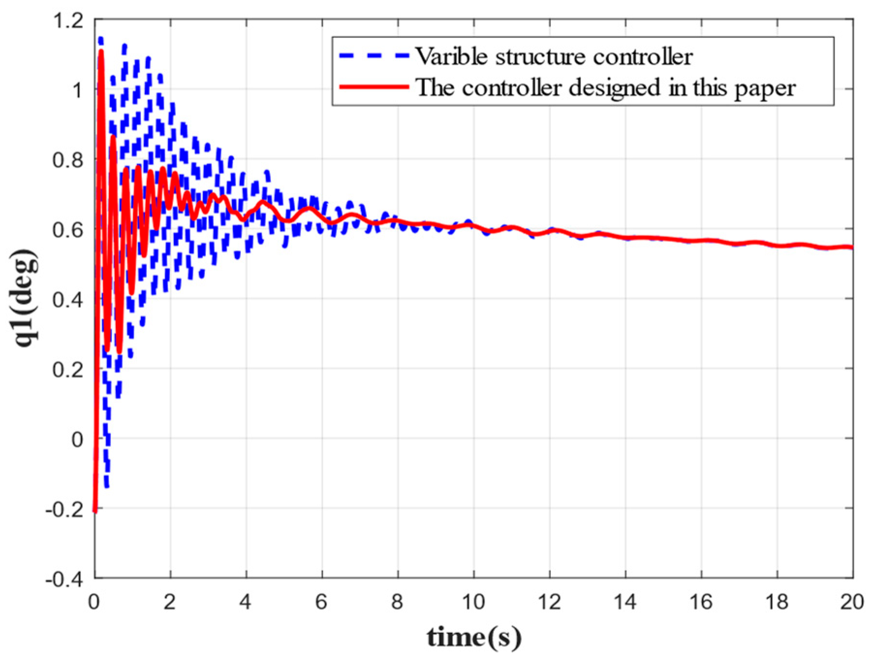
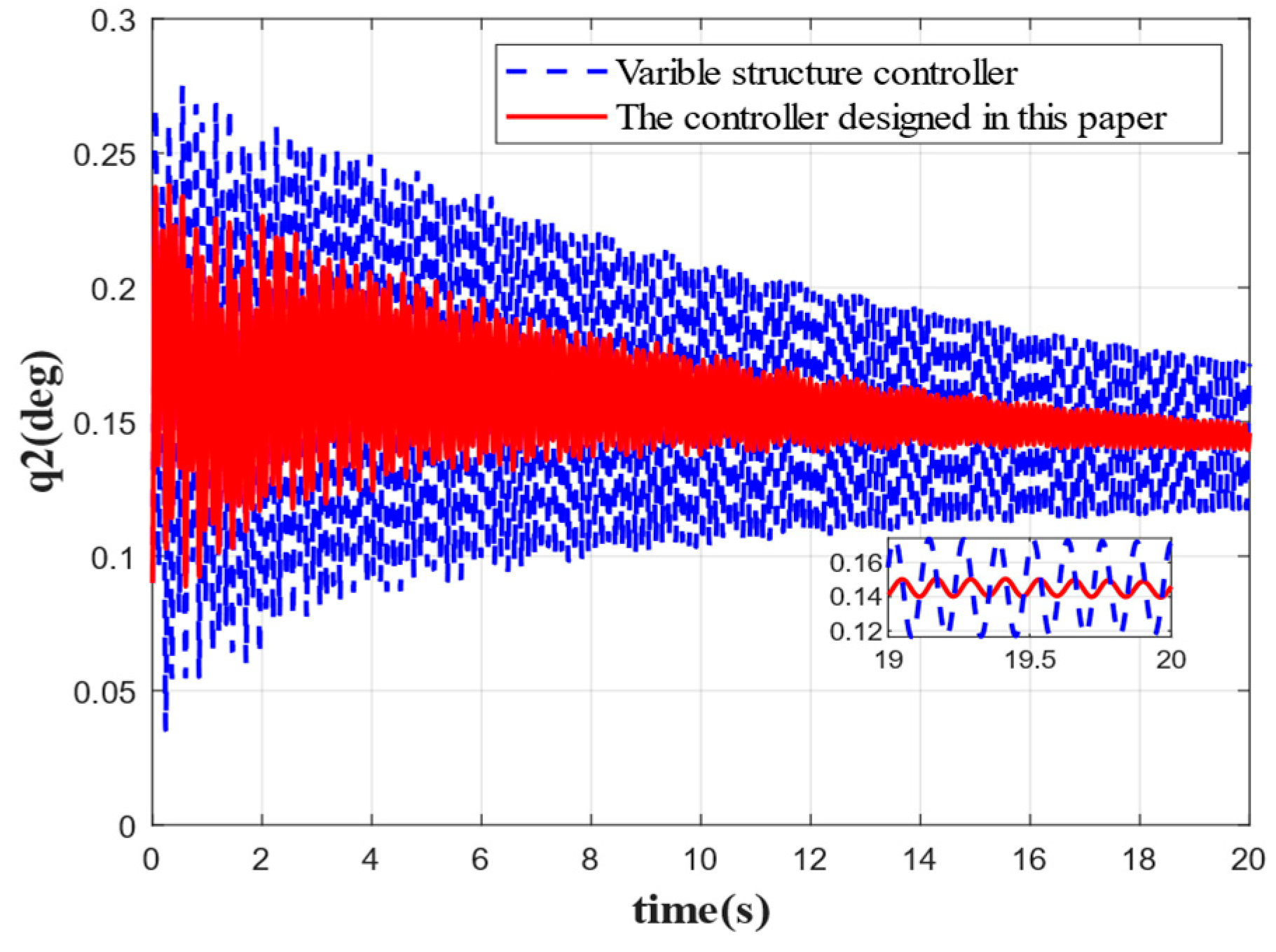
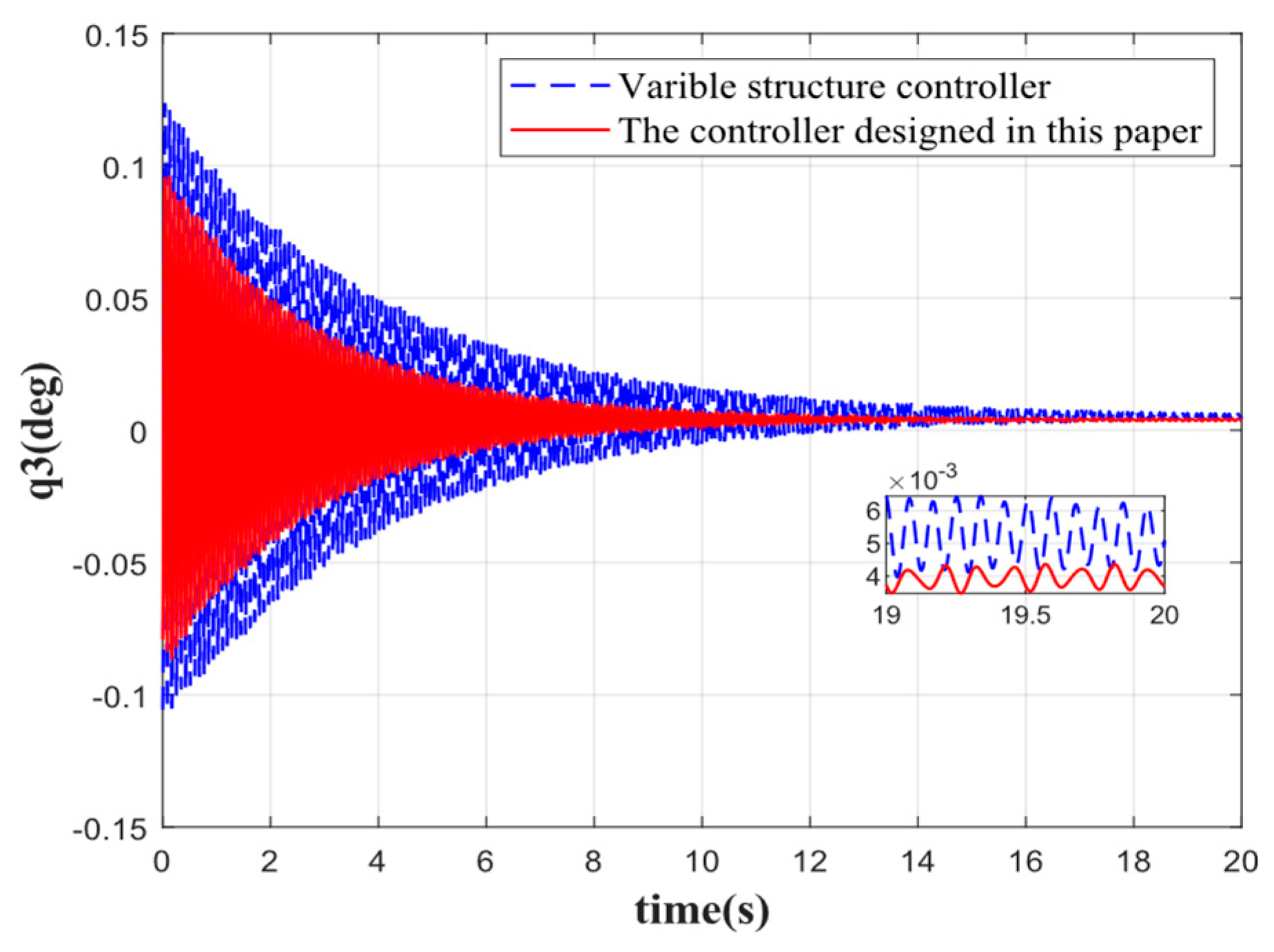
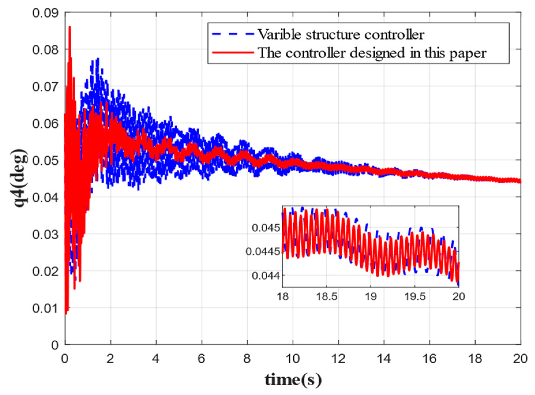
Figure 17 show the damping effect produced by each order of elastic vibration when external disturbances are considered, respectively. It can be seen from
Figure 13 that the first-order elastic vibration is basically stabilized in 2 s under the action of the controller designed in this paper. As for the traditional variable structure control method, however, it tends to be stable in 5 s. Moreover, as can be seen from the figures, different from the traditional control method, the control method proposed in this paper reduces the first-order oscillation frequency by 50%, and the oscillation amplitude is also significantly smaller. Notably, as can be seen from
Figure 14, the stabilization effect of the traditional variable structure control method for the second-order elastic vibration has diminished, while the control effect of the proposed control method is significantly better than that of the traditional control method, which indicates that the controller designed in this paper produces an excellent anti-interference performance. It can be seen from
Figure 15,
Figure 16 and
Figure 17 that for the stabilization of other orders of elastic vibration, the convergence time of the controller-stabilized elastic vibration in this paper is 8 s, 10 s, and 3 s faster than that of the traditional variable structure control, respectively. The oscillation amplitude of the proposed controller-stabilized elastic vibration is also smaller than that of the traditional variable structure control.
Figure 18 shows the comparison curve of the rudder deflection angle by considering the external interference. The maximum rudder deflection angle under the traditional control method is 1.25 deg, with convergence occurring at around 10 s. By comparison, the amplitude of the rudder deflection angle under the control method proposed in this paper is 0.75 deg, with convergence occurring at around 3 s. In addition, the rudder maintains a certain deflection angle at 20 s, which results from the control torque to be generated to offset the effect of the constant value torque in the external disturbances.
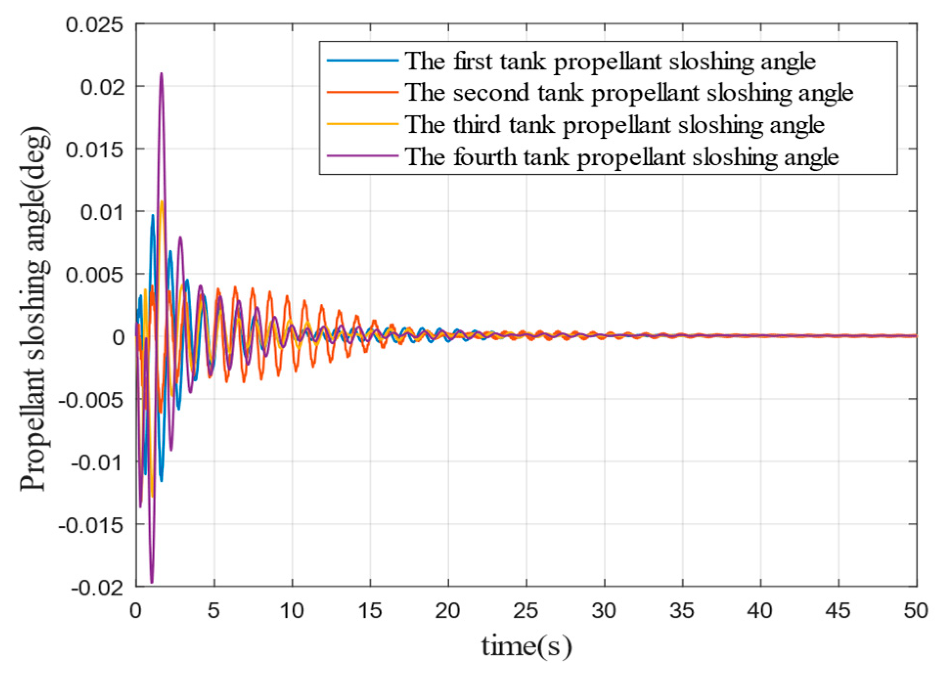
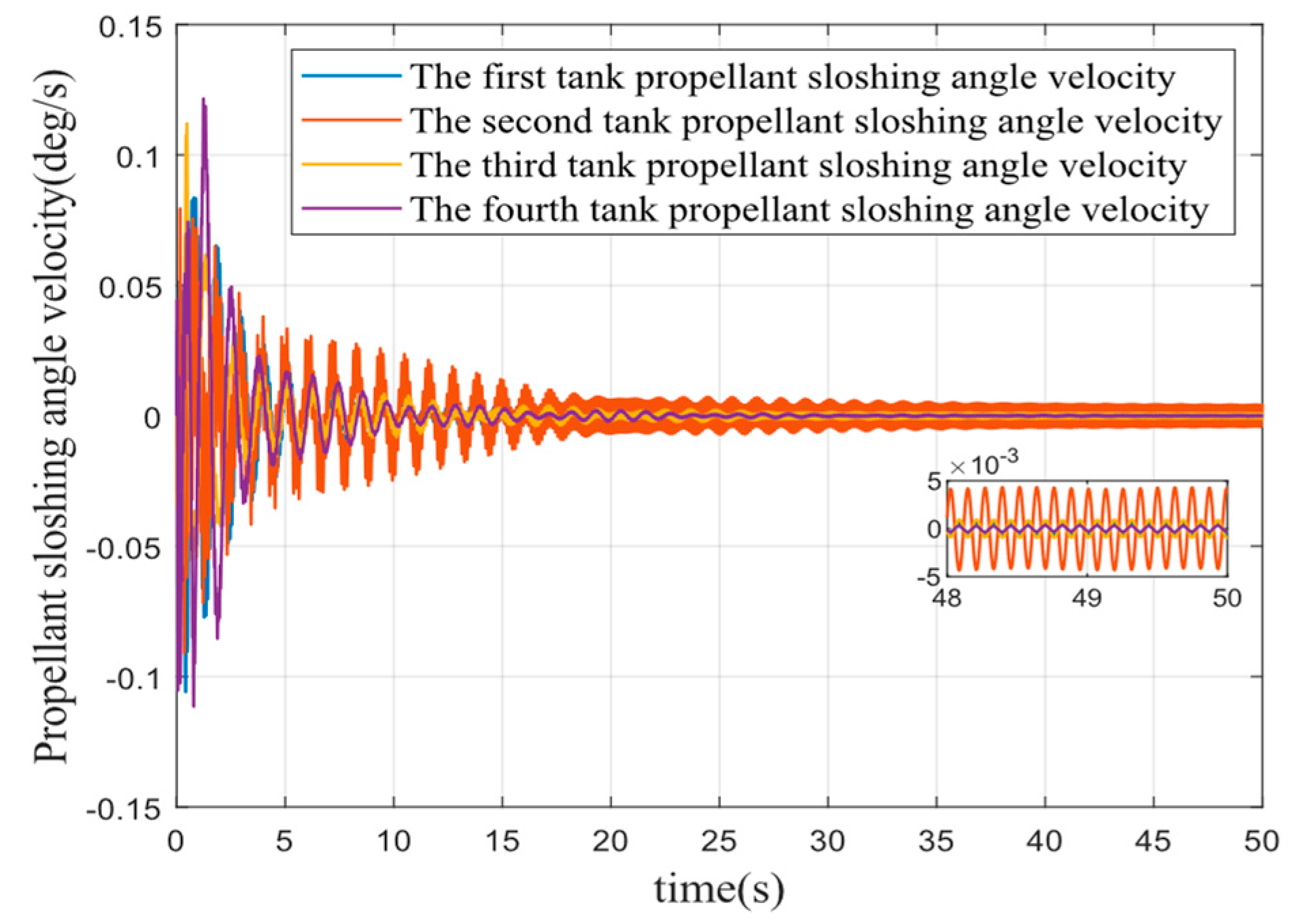
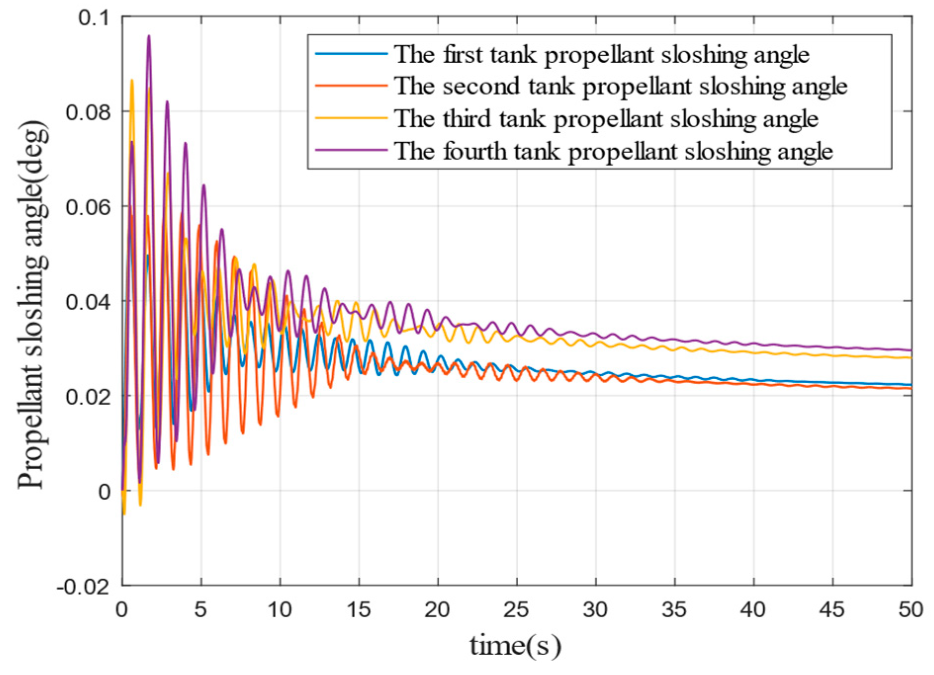
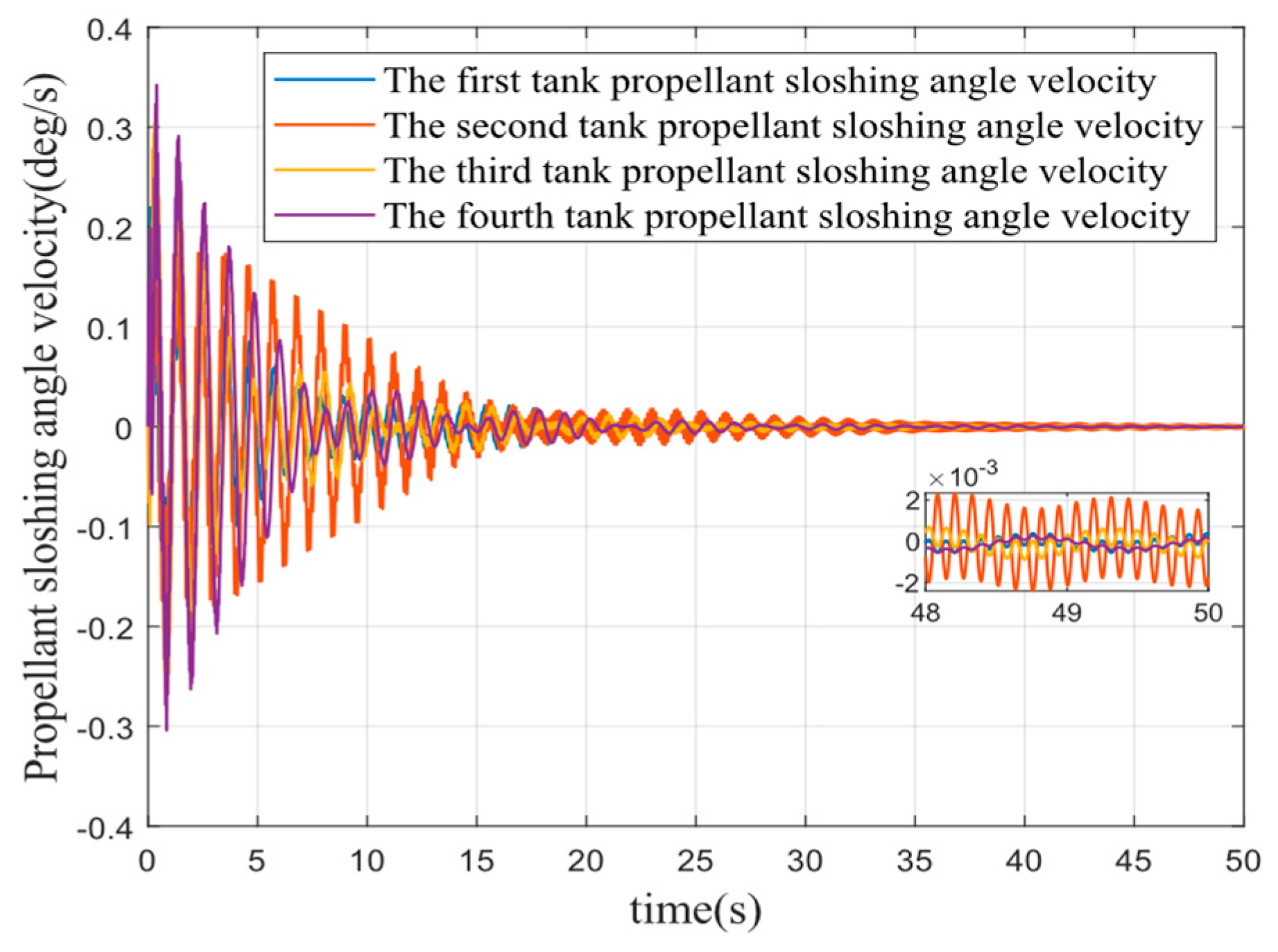
To verify that the controller designed in this paper also produces a suppression effect on liquid fuel sloshing to some extent; the parameters described in Section I are used to simulate the liquid fuel sloshing without external disturbance. The fuel sloshing angle and angular velocity are shown in
Figure 19 and
Figure 20, respectively. The parameters described in Section II are used for the simulation of liquid fuel sloshing with external disturbance, as shown in
Figure 21 and
Figure 22, respectively. The simulation time is set to 50 s and the step length is set to 0.001 s.
It can be seen from
Figure 19,
Figure 20,
Figure 21 and
Figure 22 that the attitude angle and angular velocity of liquid propellant both converge in 20 s with or without external interference. Moreover, the maximum amplitude of fuel slosh is 0.021 deg when there is no external interference, and the maximum amplitude of fuel slosh is no greater than 0.1 deg when external interference occurs. It is shown that the controller designed in this paper can be applied to the attitude control on liquid fuel for the launch vehicle.

