Article

Three-Dimensional Analytical Solutions for Acoustic Transverse Modes in a Cylindrical Duct with Axial Temperature Gradient and Non-Zero Mach Number

1
School of Astronautics, Beihang University, Beijing 100191, China
2
Aircraft and Propulsion Laboratory, Ningbo Institute of Technology, Beihang University, Ningbo 315800, China
*
Author to whom correspondence should be addressed.
Aerospace 2022, 9(10), 588; https://doi.org/10.3390/aerospace9100588
Submission received: 31 August 2022 / Revised: 3 October 2022 / Accepted: 5 October 2022 / Published: 10 October 2022

Abstract

:
Cylindrical ducts with axial mean temperature gradient and mean flows are typical elements in rocket engines, can combustors, and afterburners. Accurate analytical solutions for the acoustic waves of the longitudinal and transverse modes within these ducts can significantly improve the performance of low order acoustic network models for analyses of acoustic behaviours and combustion instabilities in these kinds of ducts. Here, we derive an acoustic wave equation as a function of pressure perturbation based on the linearised Euler equations (LEEs), and the modified WKB approximation method is applied to derive analytical solutions based on very few assumptions. The eigenvalue system is built based on the proposed solutions and applied to predict the resonant frequencies and growth rate for transverse modes. Validations of the proposed solutions are performed by comparing them to the numerical results directly calculated from the LEEs. Good agreements are found between analytical reconstruction and numerical results of three-dimensional transverse modes. The system with both mean temperature profile and mean flow presents a larger absolute value of the growth rate than the condition of either uniform mean temperature or no mean flow.

1. Introduction

Combustion instabilities are typically present in rocket engines, aero-engines and land-used gas turbine engines, and may cause severe damage due to coupling between unsteady heat release from combustion and the acoustic system within the combustors or even the entire engine [1,2]. It is thus significant to predict the combustion instabilities and optimise the engine geometries and operating conditions to eliminate these instabilities during the design stage of engines [3,4,5].
There are typically two methods to numerically predict and analyse combustion instabilities [5,6]. The first is to directly simulate the coupling mechanisms of the unsteady flow, combustion, and acoustic dynamics based on the complete three-dimensional compressible Computational Fluid Dynamics (CFD) simulations;the compressible large eddy simulation (LES) is typically preferred among these CFD solvers [5,7]. Although great achievements have been made in the development of the LES, this approach remains very expensive and time-consuming, and is difficult to use in the real engine design process [5,8,9]. The second method is to decouple the calculation of the unsteady heat release from the flame and acoustic system [10,11,12]; the first term is characterised by a flame transfer function for linear analysis or a flame describing function for weakly nonlinear analysis, see e.g., the recent reviews [13,14]. The generation, propagation, transmission, and reflection of acoustic waves, or even the entropy and vorticity waves within the combustor with complex geometries, are characterised by low order acoustic network models [15,16,17,18,19,20,21], linearised Euler equations [22,23], linearised Navier–Stokes Equations [24], Galerkin methods [25,26,27], or Helmholtz solvers [28,29] (this type of solver assumes zero mean flow and only captures the acoustic waves).
Low order acoustic network models describe the complex combustor geometry as a network of simple geometry modules with analytical solutions for acoustic waves [15,30,31,32]; the acoustic wave can be assumed to be low-dimensional, and typically the longitudinal and circumferential waves dominate [33]. Neighbouring modules are connected by transfer matrices [15,34]. The flame can be considered compact when the flame size is sufficiently short compared to the dominant acoustic wavelength [35] or can be segmented into small slices for long flames [6]. Each flame element can be considered as a module of the network model and can be embedded in the low order model by the transfer matrices [10]. By substituting the flame transfer function or flame describing function into it, the low order acoustic network model method has been successfully used to predict the combustion instabilities [6,12,36,37] and test the performance of control approaches in different kinds of combustors [4,38].
Due to heat losses, reactant dilution, and further combustion of unburned fuels, axially varying mean temperatures and mean flows are typically present in the combustion chamber [9,39,40]. The consequent distribution of flow properties, often neglected in the analytical acoustic solutions, can significantly affect the sound propagation and instabilities within the thermoacoustic system [41,42,43]. It is necessary to develop analytical solutions for acoustic waves travelling through the inhomogeneous mean field [43,44,45,46,47,48], which both improves the performance of the low order acoustic network model and enhances the resulting physical insights into the acoustic wave behaviours within these elements [49].
Extensive studies of the analytical solution for the duct acoustic field with axial mean temperature gradient and mean flow are typically conducted in straight ducts for pure longitudinal waves [47,50,51]. Readers can refer to our previous work [43] for a review of previous studies. However, these are not valid and reliable when the radial modes and transverse modes [9,23,52] are considered in rocket combustion chambers, can combustors, or afterburners in the presence of mean temperature gradient and mean flow. In our previous works, analytical solutions have been obtained for one-dimensional straight ducts [43] and the thin annular ducts [53] with arbitrary axial temperature gradient and mean flow by means of a modified WKB approximation. Cummings [51] has used this method to deal with the acoustic wave equation with spatially varying coefficients, and it is valid for high frequencies and low flow Mach numbers. It thus has a natural advantage in dealing with transverse acoustic oscillations, which typically occur at high frequencies. Recently, an exact analytical solution has been derived for a cylindrical duct with an axial varying mean temperature considered, however, it is only used when there is no mean flow [54]. The effects of the axial mean temperature gradient and the inhomogeneous flow Mach number are not appropriately considered in low order modelling for three-dimensional thermoacoustic systems.
Based on the previous work, the second-order partial differential wave equation in the form of pressure perturbation is derived from linearised Euler equations in Section 2. A separable strategy and the modified WKB approximation method are combined to deal with an axial ODE with varying coefficients. The analytical solution of the three-dimensional acoustic field is derived subsequently in Section 3. The case of zero mean flow is treated separately in Section 4. The performance of the proposed solutions for transverse modes are evaluated with the prescribed configuration and compared to the numerical results from the LEEs in Section 5. A eigenvalue system is built based on the proposed solutions to predict the resonant frequencies and growth rates for three transverse modes in Section 6. Finally, conclusions are drawn in Section 7.

2. Wave Equation for Three-Dimensional Acoustic Waves

A straight cylindrical duct is subjected to both a mean axial flow and an axial mean temperature gradient, as sketched in Figure 1. For compressible ideal gas with constant mass and flux, and conserved mass, momentum, and energy, the Euler equations and equation of state are expressed as follows:
D ρ D t + ρ · u = 0 ,
ρ D u D t + p = 0 ,
1 γ p D p D t + · u = γ 1 γ p q ˙ ,
p = ρ R g T .
where ρ , u = ( u x , u θ , u r ) , p denote the density, velocity components, and pressure, respectively, q ˙ represents heat flux, and the heat capacity ratio γ and universal gas constant R g are assumed to be constant along the cylindrical duct.
To linearise the Euler equations, the primitive variables are assumed to be the sum of a time-average steady component that is denoted by ( ) ¯ and a small time-varying perturbation in the form of time and angular periodic dependence, expressed as a = a ¯ + a ^ ( x , r ) exp ( i ω t + i n θ θ ) , where ω = 2 π f + i ω i is the complex angular frequency and the circumferential wavenumber n θ is definitely an integer due to the continuity in the θ direction. It should be noted that ω i < 0 denotes that the corresponding thermoacoustic mode is unstable.
The conservation relations for the steady flow variables are deduced, and can be written as follows:
1 ρ ¯ d ρ ¯ d x + 1 u ¯ x d u ¯ x d x = 0 ,
ρ ¯ u ¯ x d u ¯ x d x + d p ¯ d x = 0 ,
u ¯ x γ p ¯ d p ¯ d x + d u ¯ x d x = γ 1 γ p ¯ q ˙ ¯ .
With a prescribed mean temperature profile T ¯ ( x ) , the consequent inhomogeneous mean flow field can be calculated along the axial direction. For greater convenience of subsequent derivation, the derivatives of the steady flow variables are expressed in the form of the relative density derivative and steady variables, written as follows:
α = 1 ρ ¯ d ρ ¯ d x , d u ¯ x d x = u ¯ x α , d p ¯ d x = ρ ¯ u ¯ x 2 α ,
q ˙ ¯ = ρ ¯ u ¯ x c p d T ¯ d x + u ¯ x d u ¯ x d x = u ¯ x 2 c ¯ 2 γ 1 ρ ¯ u ¯ x α
where c ¯ = ( γ R g T ¯ ) 1 / 2 is the local sound speed.
Then, the first derivatives of the steady temperature, speed of sound, mean flow Mach number M x = u ¯ x / c ¯ , and local wave number k 0 = ω / c ¯ are expressed as follows:
d T ¯ d x = ( 1 γ M x 2 ) T ¯ α , d c ¯ d x = 1 γ M x 2 2 c ¯ α , d M x d x = 1 + γ M x 2 2 M x α , d k 0 d x = 1 γ M x 2 2 k 0 α .
It is evident that the axial temperature gradient is associated with the steady heat flux in the presence of non-zero mean flow. Therefore, the mean temperature gradient can be maintained by steady heat addition or extraction when the mean flow propagates through the three-dimensional cylindrical duct.
For the perturbation variables, the linearised Euler equations (LEEs) of the energy and momentum can be obtained:
i ω + γ d u ¯ x d x p ^ + u ¯ x p ^ x + d p ¯ d x u ^ x + γ p ¯ u ^ x x + γ p ¯ i n θ r u ^ θ + γ p ¯ ( u ^ r r + u ^ r r ) = 0 ,
i ω + d u ¯ x d x u ^ x + u ¯ x u ^ x x + 1 ρ ¯ p ^ x + u ¯ x d u ¯ x d x 1 γ p ¯ p ^ u ¯ x d u ¯ x d x s ^ c p = 0 ,
u ¯ x u ^ r x + i ω u ^ r + 1 ρ ¯ p ^ r = 0 ,
u ¯ x u ^ θ x + i ω u ^ θ + i n θ ρ ¯ r p ^ = 0 ,
where s ^ denotes the entropy perturbation, which is introduced by the relation s ^ / c p = p ^ / γ p ¯ ρ ^ / ρ ¯ to replace the density perturbation in the axial momentum LEE by the pressure perturbation and entropy wave. Here, c p = γ R g / ( γ 1 ) is the heat capacity at constant pressure. With the unsteady heat flux q ˙ set to zero, only the steady heat communication is taken into account.
Considering the coupling term of u ¯ x ( d u ¯ x / d x ) ( s ^ / c p ) in Equation (12), the entropy wave is generated during the acoustic wave travelling through the inhomogeneous mean temperature zone and in return affects the acoustic field in the presence of non-uniform mean velocity. It has been validated that the sound regeneration of the entropy wave convected by the mean flow can be neglected, especially in the high-frequency domain [43,55]. Therefore, the axial momentum LEE (Equation (12)) is further simplified by neglecting the acoustic–entropy coupling term, provided by
i ω + d u ¯ x d x u ^ x + u ¯ x u ^ x x + 1 ρ ¯ p ^ x + u ¯ x d u ¯ x d x 1 γ p ¯ p ^ = 0
A pure acoustic problem is derived, facilitating the acoustic wave equation and analytical solutions.
Assuming that the wave number is sufficiently larger than the critical value, | k 0 | | M x α | , and terms with order higher than M x 2 can be ignored, Equation (15) can be divided by i ω + d u ¯ x / d x to eliminate the term ( d p ¯ / d x ) u ^ x in Equation (11), leading to
i ω γ p ¯ u ¯ x p ¯ α p ^ + M x 2 ρ ¯ u ¯ x 1 M x α i k 0 p ^ x + u ^ x x = i n r u ^ θ u ^ r r u ^ r r .
Then, Equation (15) is divided by u ¯ x , expressed as
i k 0 M x α u ^ x + u ^ x x + 1 ρ ¯ u ¯ x p ^ x M x 2 α ρ ¯ u ¯ x p ^ = 0 .
Subsequently, Equation (16) and Equation (17) are manipulated according to following formula:
ρ u ¯ x i k 0 M x α · x Equation (17) Equation (16) i k 0 / M x α Equation (16) .
Following the above procedure, all terms with u ^ x on the left-hand side (LHS) of the consequent formula are eliminated, and the terms u ^ θ and u ^ r on the right-hand side (RHS) can be replaced with the terms of the pressure perturbation in the linearised radial and azimuthal momentum equations (Equations (13) and (14)), written as follows:
1 M x 2 + i 2 M x 2 k 0 d M x d x 2 p ^ x 2 1 ( 3 + γ ) M x 2 α + i 2 M x k 0 1 + β 2 k 0 2 α 2 k 0 2 p ^ x + k 0 2 1 + ( 2 γ ) M x 2 β k 0 2 + ( 4 γ 5 ) M x 2 α 2 k 0 2 + i k 0 M x α ( 2 + γ γ M x 2 ) p ^ = 1 M x α i k 0 2 2 p ^ r 2 1 r p ^ r + n θ 2 r 2 p ^ .
where β = d 2 ρ ¯ / d x 2 / ρ ¯ .
Dividing both sides by the x-dependent coefficient ( 1 M x α / i k 0 ) 2 and assuming that | k 0 | | α | and | k 0 2 | | β | / 2 , we finally obtain the wave equation in the form of pressure perturbation only, expressed as follows:
1 M x 2 i 2 M x α k 0 2 p ^ x 2 1 ( 1 + γ ) M x 2 α + i 2 M x k 0 p ^ x + k 0 2 + i γ M x k 0 α p ^ = 2 p ^ r 2 1 r p ^ r + n θ 2 r 2 p ^ .
The general PDE in the form of pressure perturbation is ultimately obtained from the governed equations with the assumption of a sufficiently large wave number and the negligible effect of entropy perturbation in such a high-frequency domain. This allows for the derivation of the analytical expression of the pressure perturbation in the next section and the theoretical reconstruction of three-dimensional acoustic waves in the inhomogeneous background mean field.

3. Analytical Solutions of Three-Dimensional Acoustic Wave

The partial differential wave equation (Equation (20)) is characterized by partial derivatives and coefficients concerning x and r on the LHS and RHS, respectively. Therefore, separation of variables can be applied by substituting p ^ ( x , r ) = X ( x ) R ( r ) into the wave equation, resulting in the radial and axial ordinary differential equations (ODEs):
d 2 R ( r ) d r 2 + 1 r d R ( r ) d r + λ 2 n θ 2 r 2 R ( r ) = 0 ,
and
1 M x 2 i 2 M x α k 0 d 2 X ( x ) d x 2 1 ( 1 + γ ) M x 2 α + i 2 M x k 0 d X ( x ) d x + k 0 2 λ 2 + i γ M x k 0 α X ( x ) = 0
where λ is a constant that is independent of the radial and axial directions.
For the radial component, the solution for the Bessel equation can be written as the superposition of two linearly independent Bessel functions:
R ( r ) = c 1 J n θ ( λ r ) + c 2 Y n θ ( λ r ) ,
where J n θ and Y n θ are the Bessel functions of the first and second kind. Note that the coefficient c 2 must be 0, as Y n θ diverges as r tends to 0.
With the rigid-wall boundary condition at r = r 0 ,
d J n θ ( λ r ) d r | r = r 0 = 0 ,
a series of discrete solutions for the constant λ is calculated and corresponds to different acoustic transverse modes labelled ( n θ , n r ) , where n r denotes the ( n r + 1 ) th solution for each value of n θ .

3.1. Analytical Solutions of the Axial ODE Using a Modified WKB Approximation Method

For the axial component, no known solutions can directly deal with spatially varying coefficients of the axial ODE (Equation (22)), especially in the presence of both the axially arbitrary temperature profile and mean flow. The modified WKB approximation method is then used to resolve the axial ODE, which is essentially based on the large wave number assumption and successfully applied on the one-dimensional acoustic wave equation within varying coefficients [43].
The modified WKB solution uses the form of the separate amplitude and phase factors to represent the properties of the acoustic wave propagating through the axially varying mean field, expressed as follows:
X ( x ) = C exp x 1 x a ( x ) + i b ( x ) d x .
where C is a constant coefficient and a and b are x-dependent real variables. The assumption of a larger wave number naturally results in the precondition of | b | | a | within the modified WKB solution.
To obtain real variables a and b, the locally complex wave number k 0 = ω / c ¯ = k r + i k i has to be substituted into Equation (22) by assuming | k r | | M x k i | , provided by
1 M x 2 i 2 M x α k r d 2 X ( x ) d x 2 1 ( 1 + γ ) M x 2 α 2 M x k i + i 2 M x k r d X ( x ) d x + k r 2 λ 2 γ k i M x α + i 2 k r k i + i γ k r M x α X ( x ) = 0 .
Then, the axial ODE can be transformed into an algebraic equation using the modified WKB solution, written as
1 M x 2 i 2 M x α k r a 2 b 2 + i 2 a b + d a d x + i d b d x 1 ( 1 + γ ) M x 2 α 2 M x k i + i 2 M x k r a + i b + k r 2 λ 2 γ k i M x α + i 2 k r k i + i γ k r M x α = 0 .
The real part is further simplified by combining previous assumptions for the larger wave number, | k 0 | | α | , | b | | a | and | k r | | M x k i | , expressed as:
1 M x 2 b 2 + 2 M x k r b + k r 2 λ 2 = 0 .
The solutions of b are directly written as
b ± = k r M x 1 1 M x 2 λ 2 / k r 2 1 M x 2 = k r M x η 1 M x 2 .
Hence, the cut-off frequency f c is provided by
f c = λ 2 π max c ¯ 1 M x 2 .
It should be noted that this work only considers the condition ω > ω c in order to make sure that the formula under the square root is always positive, as acoustic waves often rapidly dissipate with axial distance when ω < ω c .
Solutions of a are further derived by substitute b ± into the imaginary part, respectively,
a ± = α 2 1 2 k x d k x d x γ 1 2 η η + M x M x α k i M x η 1 M x 2 ± k i λ 2 k x k r
where k x = η k r .
The analytical solution of X is thus assumed to be the superposition of plane waves propagating downstream and upstream. Then, the solution of pressure perturbation p ^ can be expressed as
p ^ x , r , ω = X x R r = C 1 X + x , ω + C 2 X x , ω J n θ ( λ r ) ,
where
X ± = ρ ¯ k x , 1 ρ ¯ 1 k x 1 / 2 exp γ 1 η M x 2 η M x exp γ 1 η M x , 1 2 η M x , 1 exp ± ω i λ 2 ω r x 1 x 1 k x d x exp i ω x 1 x M x η c ¯ ( 1 M x 2 ) d x ,
and the subscript ‘1’ represents variables at the inlet. Coefficients C 1 and C 2 can be calculated by the given axial boundary conditions and the constant λ is determined by the mode numbers n θ and n r .

3.2. Solutions of the Three-Dimensional Velocity Perturbations

With the proposed solution of p ^ in the separated form, the radial and azimuthal momentum LEEs in Equations (13) and (14) can be transformed into non-homogeneous differential equations for u ^ r and u ^ θ . Consequently, corresponding analytical solutions can be derived directly via the variation of constants method, expressed as follows:
u ^ θ x , r , ω = C 3 exp x i ω u ¯ x d x + V ( x , ω ) · i n θ r J n θ ( λ r ) ,
u ^ r x , r , ω = C 4 exp x i ω u ¯ x d x + V ( x , ω ) · d J n θ ( λ r ) d r ,
where
V ( x , ω ) = exp x i ω u ¯ x d x · x X x ρ ¯ u ¯ x exp x i ω u ¯ x d x d x .
Coefficients C 3 and C 4 are determined by the relevant boundary conditions or the initial values of the radial and azimuthal velocity perturbations. For example, C 3 and C 4 equal zero when there are no radial and azimuthal velocity perturbations at the inlet ( u ^ r ( x 1 ) = u ^ θ ( x 1 ) = 0 ). Furthermore, a zero axial component of the vorticity perturbation ( ξ x = 0 ) in the incoming flow naturally provides the condition of C 3 = C 4 (this is discussed in Section 6).
Compared to sound waves travelling at the speed of sound, radial and azimuthal velocity disturbances involve waves propagating downstream at the axial mean flow velocity u ¯ x . Typically, these convection waves are associated with the development of the vorticity wave during the propagation of acoustic waves in the inhomogeneous background field [22,45,46].
Subtracting Equation (16) from Equation (17) yields a formula that does not contain the first derivative of u ^ x :
i k 0 M x α u ^ x M x 2 α ρ ¯ u ¯ x + i ω γ p ¯ u ¯ x p ¯ α p ^ + 1 ρ ¯ u ¯ x M x 2 ρ ¯ u ¯ x 1 M x α i k 0 p ^ x = i n r u ^ θ + u ^ r r + u ^ r r
Then, the axial velocity perturbation u ^ x is easily obtained by substituting the solutions of the pressure and transverse velocity components into Equation (35). It should be noted that the r-derivatives of the Bessel function J n θ ( λ r ) introduced by u ^ r and u ^ θ can be eliminated according to the Bessel equation of the radial component in the Equation (21). Therefore, the explicit expression is as follows:
u ^ x x , r , ω = A + i k 0 M x α · C 1 X + ρ ¯ c ¯ A i k 0 M x α · C 2 X ρ ¯ c ¯ · J n θ ( λ r ) + M x i k 0 M x α λ 2 V ( x , ω ) λ 2 C 4 exp x i ω u ¯ x d x = 0 if u ^ r ( x 1 ) = 0 ( C 3 C 4 ) n θ 2 r 2 exp x i ω u ¯ x d x = 0 C 3 = C 4 , if ξ x ( x 1 ) = 0 · J n θ ( λ r ) ,
where
A ± = i k x k i η α 4 η 2 1 + 2 η 2 ± 2 η M x γ 1 + 2 η 2
and the terms with order higher than M x 2 are always neglected in the solutions. It is obvious that the axial velocity perturbation involves both the acoustic and convective waves at the same time. The latter greatly affects the resonant frequencies and growth rate of three-dimensional combustors that have a velocity-dependence end, for example, an acoustically closed outlet. There are a total of four constant coefficients from C 1 to C 4 in the solutions of pressure and velocity perturbations that are determined by boundary conditions or initial values.
Finally, Equations (32), (33), and (36) constitute our analytical solutions of the three-dimensional acoustic field, which should satisfy the high-frequency assumption | k 0 | | α | (the local wave number is sufficiently larger than the critical value) and that Mach number terms with order higher than M x 2 can be neglected. It should be noted that these proposed analytical solutions are not limited to the distribution forms of continuous axial mean temperature profiles.

4. Case of Zero Mean Flow

An assumption of zero mean flow is typically applied to the combustion chambers when Mach numbers are sufficiently small ( M x 0 ). Therefore, the case of no mean flow is treated separately in this subsection and represents a benchmark result to present how the axial mean temperature gradient affects the thermoacoustic properties of the cylindrical combustion chamber containing the mean flow.
Substituting M x = 0 into the Equation (26) leads to the wave equation for the case of no mean flow:
d 2 X ( x ) d x 2 α d X ( x ) d x + k r 2 λ 2 + i 2 k r k i X ( x ) = 0 .
This coincides with the axial wave equation directly obtained from the LEEs for no mean flow (Equation (16) in our previous work [54]) if the imaginary part, as stated in the earlier text, is assumed to be sufficiently small, i.e., | k r | | M x k i | .
The modified WKB method is used again to deal with spatially varying coefficients of the ODE, and solutions of b and a are derived by assuming | k 0 | | α | , expressed as follows:
b 0 ± = k x = k r 2 λ 2 , a 0 ± = α 2 1 2 k x d k x d x ± k r k i k x
where the subscript ‘0’ denotes the condition of no mean flow.
The solution of the pressure perturbation is subsequently provided by
X 0 x = C 1 X 0 + x , ω + C 2 X 0 x , ω
where
X 0 ± x , ω = ρ ¯ k x , 1 ρ ¯ 1 k x 1 / 2 exp x 1 x ± ω r ω i c ¯ 2 k x d x exp x 1 x i k x d x , k x = k r 2 λ 2 .
Then, the axial velocity is derived from the momentum LEEs in the condition of zero mean flow, expressed as
u ^ x ( x , r , ω ) = i ρ ¯ ω d X 0 ( x ) d x J n θ λ r = i ρ ¯ ω α 2 k r 2 α 4 k x 2 ± k r k i k x i k x X 0 ( x ) J n θ λ r .
The radial and circumferential velocity perturbations have degenerated expressions, provided by
u ^ r ( x , r , ω ) = i ρ ¯ ω X 0 ( x ) d J n θ λ r d r ,
and
u ^ θ ( x , r , ω ) = n θ r ρ ¯ ω X 0 ( x ) J n θ λ r .
The analytical expressions for the three-dimensional acoustic field are finally derived in the case of zero Mach number. The two constant coefficients in the proposed solutions, C 1 and C 2 , can be determined by acoustic boundary conditions.

5. Sound Responses to Forced Inlet Pressure Perturbations

5.1. Validation Configuration

The proposed solutions are applied to predict the three-dimensional acoustic field for a straight cylindrical duct with the mean temperature profile T ¯ ( x ) and the inlet flow Mach number M x , 1 . A linear temperature distribution is accounted for, with the expression
T ¯ x = T ¯ 1 T ¯ 1 T ¯ 2 l x x 1 , x [ x 1 , x 1 + l ] ,
where the axial mean temperature decreases from T ¯ 1 at the inlet, x = x 1 = 0 , to T ¯ 2 at x = l .
In order to validate the analytical solutions, the following boundary conditions are chosen for the inlet and outlet. An external pressure perturbation p ^ i n ( x = 0 , r , θ ) = p ^ 1 J n θ ( λ r ) exp ( i n θ θ ) is prescribed at the duct inlet and a pressure release condition p ^ o u t ( x = l , r , θ ) = 0 is prescribed at the outlet.
A dimensionless frequency is defined by Ω = f l / c ¯ 1 . The frequency larger than cut-off frequency, ω > ω c , is re-written as follows:
Ω > Ω c = l 2 π λ 1 M x , 1 2 1 / 2 .
Certain dimensionless transfer functions from p ^ 1 to acoustic perturbations are defined as functions of geometric positions and the forcing frequency,
F p ( x , r , θ , f ) = p ^ p ^ 1 , F u x ( x , r , θ , f ) = ρ ¯ c ¯ u ^ x p ^ 1 .
It is important that the analytical model has the almost same linearised Euler equations with the exception of the negligible entropic effect on the high-frequency acoustic waves. Hence, the proposed analytical solutions can be well verified by comparing them to the numerical results from LEEs.
Table 1 presents the parameters used in the analyses in the next subsection.

5.2. Reconstructions of Sound Responses

In this subsection, the proposed analytical solution is validated by comparing the predicted three-dimensional acoustic field to the results of the numerical LEEs.
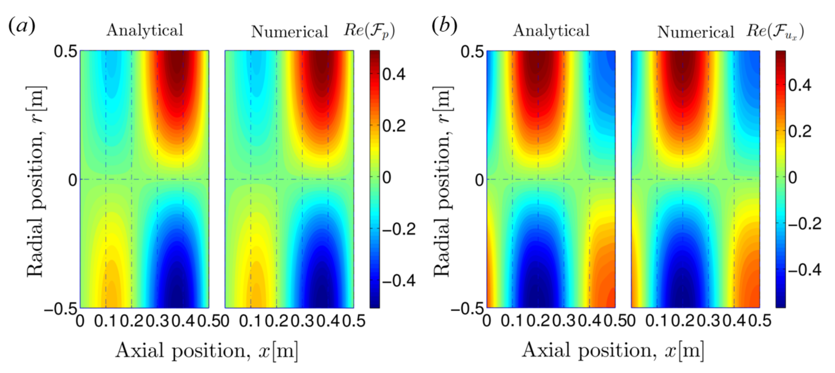
For the first transverse (1T) mode, n θ = 1 and n r = 0 , dimensionless transfer functions are calculated analytically on the plane θ = π / 2 when Ω = 0.8 and M x , 1 = 0.2 . As shown in Figure 2, our proposed solutions accurately reconstruct the three-dimensional acoustic field compared to the numerical results from LEEs.
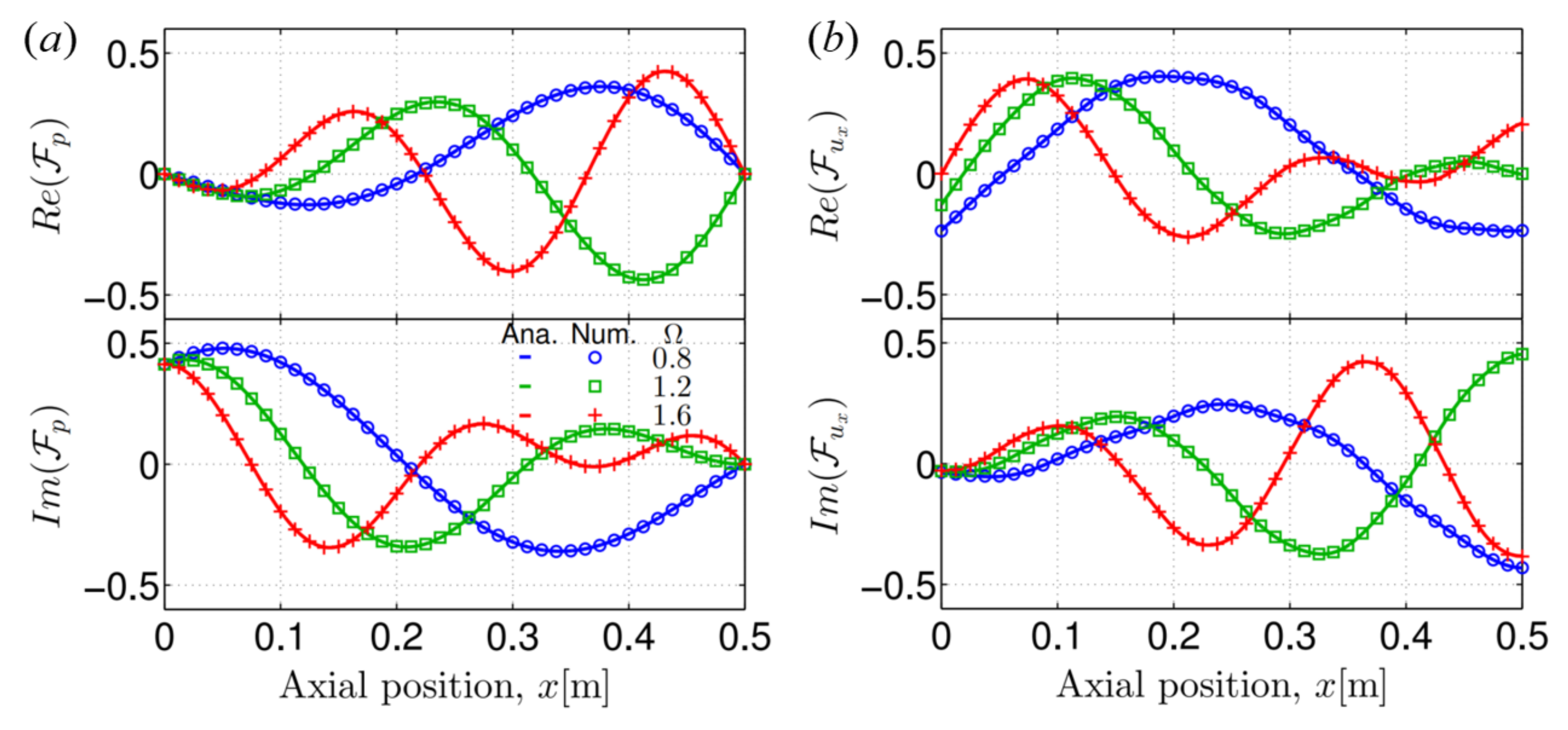
Figure 3 presents the real and imaginary parts of F p and F u x along an axial line of ( r , θ ) = ( r 0 / 2 , π / 2 ) for the 1T mode. The analytical solutions agree well with the numerical results, with the reduced forcing frequency Ω being 0.8 , 1.2 , and 1.6 , respectively.
It is worth noting that the high-frequency condition of the modified WKB method, that is, | k 0 | | α | , can be re-written in the form of a dimensionless frequency:
Ω Ω 0 = l 2 π c ¯ 1 max | α | c ¯ .
The cut-off frequency Ω c for a transverse mode ( λ 0 ) often provides a much larger critical value than Ω 0 .
Ω c = l 2 π λ 1 M x , 1 2 1 / 2 Ω 0
Therefore, the high-frequency assumption has almost no effect on the accuracy of the proposed analytical solutions when applied to the transverse acoustic field. High precision can be achieved when the forced frequency of the perturbation is slightly different from the cut-off frequency.

6. Predictions of Resonant Frequencies and Linear Instabilities for Transverse Modes

6.1. Boundary Conditions and Eigenvalue Matrix

In this subsection, the proposed three-dimensional pressure and velocity solutions are applied to a cylindrical duct containing an axial mean temperature profile and a mean flow, then used to predict transverse modes. For the incoming flow ( x = 0 ) at the inlet, no vorticity perturbation is assumed upstream of the varying temperature region.
The flow vorticity is derived by taking the curl of the three-dimensional velocity vector u , expressed as follows:
ξ = × u = ξ x e x + ξ r e r + ξ θ e θ = 1 r r u θ r 1 r u r θ e x + 1 r u x θ 1 r r u θ x e r + u r x u x r e θ
The components for the vorticity vector can be calculated by substituting the proposed velocity solutions. Then, the zero vorticity perturbation at the inlet can be expressed in the form of four coefficients C 1 C 4 , written as
ξ ^ x ( x = 0 ) = C 3 C 4 = 0
ξ ^ r ( x = 0 ) = 1 ρ ¯ 1 c ¯ 1 A 1 + Δ + 1 ρ ¯ 1 u ¯ 1 C 1 1 ρ ¯ 1 c ¯ 1 A 1 Δ 1 ρ ¯ 1 u ¯ 1 C 2 + i ω u ¯ 1 λ 2 Δ C 4 + i ω u ¯ 1 n 2 r 2 Δ C 3 C 4 = 0 , if ξ ^ x ( x = 0 ) = 0 = 0
ξ ^ θ ( x = 0 ) = 1 ρ ¯ 1 c ¯ 1 A 1 + Δ + 1 ρ ¯ 1 u ¯ 1 C 1 1 ρ ¯ 1 c ¯ 1 A 1 Δ 1 ρ ¯ 1 u ¯ 1 C 2 + i ω u ¯ 1 λ 2 Δ C 4 n 2 r 2 Δ C 3 C 4 = 0 , if ξ ^ x ( x = 0 ) = 0 = 0
where Δ = i k 0 , 1 M x , 1 α 1 . These zero vorticity conditions can provide two equations, as the radial and circumferential components have the same expressions when the axial vorticity equals zero.
Another two equations can be provided by acoustic boundary conditions at the inlet and outlet, e.g., the open end ( p ^ = 0 ) and acoustically closed end ( u ^ x = 0 ) boundary conditions.
The eigenvalue system is consequently built by combining four boundary conditions of the duct ends, expressed as
M · C 1 C 2 C 3 C 4 T = 0 .
The complex angular frequency ω = 2 π f + i ω i can be solved by letting the determinant of the eigenvalue matrix M be zero, where ω i < 0 denotes that the corresponding thermoacoustic mode is unstable.

6.2. Effect of Mean Flow and Temperature Gradient on Resonant Frequencies and Instabilities

Predictions for the first transverse mode (1T) are carried out for the eigenvalue system in the presence of different outlet mean temperatures T ¯ 2 . Two kinds of boundary conditions are prescribed at the inlet and outlet, namely, both open end boundary conditions or both acoustically closed ends. The latter is representative of the inlets and outlets of many real combustion chambers.
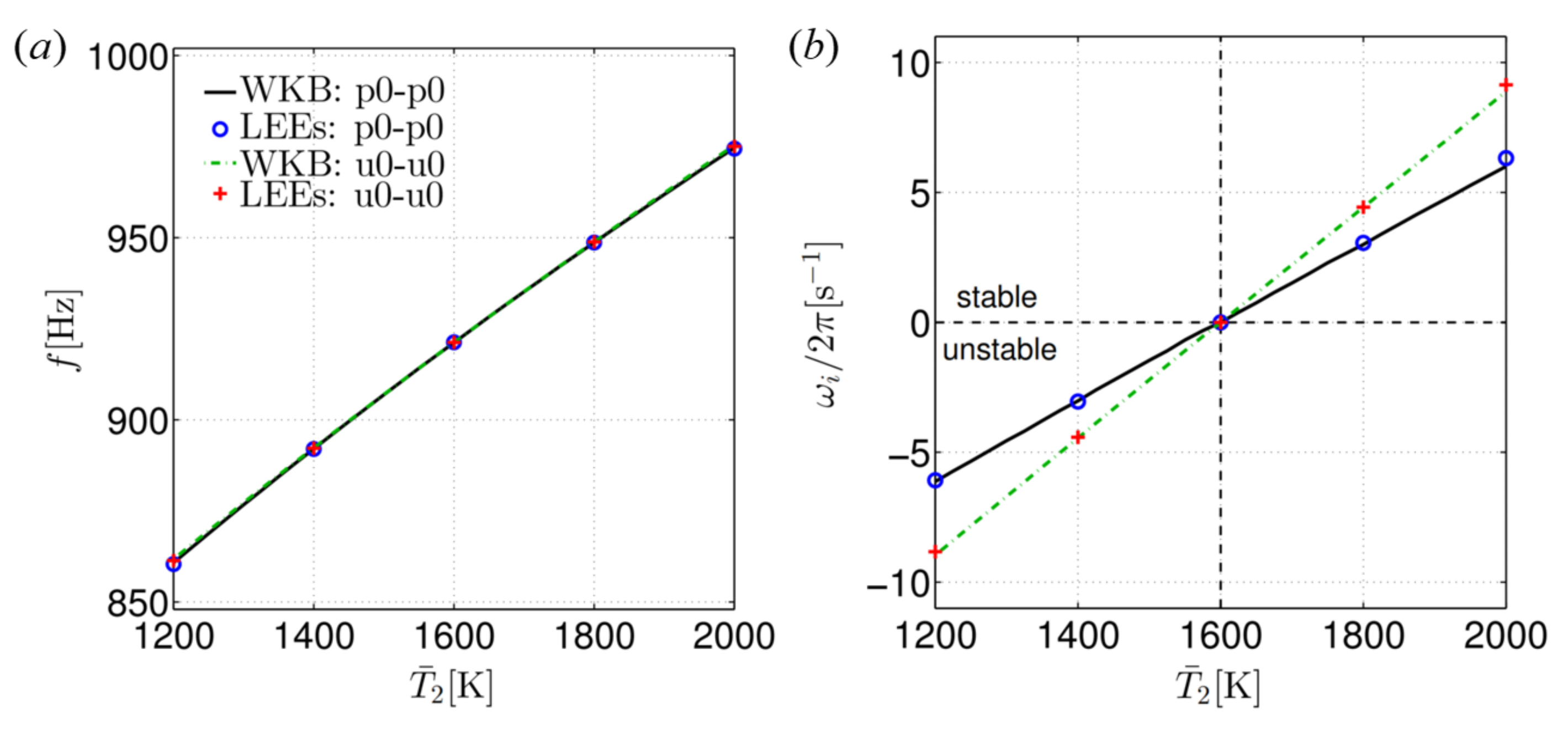
As shown in Figure 4, the frequencies and growth rates of the thermoacoustic modes vary with the outlet mean temperature T ¯ 2 . Good agreements are found between analytical solutions and numerical LEE results for both kinds of boundary conditions. When the outlet mean temperature increases, the spatially averaged speed of sound increases, which results in a higher resonant frequency. It is clear that when the duct outlet temperature T ¯ 2 differs substantially from the inlet temperature T ¯ 1 , the growth rate does not equal zero. A decrease in axial mean temperature leads to an unstable mode, while temperature increase corresponds to a stable mode. The resonant frequencies for the open–open ends are almost same as those of the closed–closed ends. However, the growth rates for the closed–closed ends have larger absolute values irrespective of whether the thermoacoustic modes are stable or unstable.
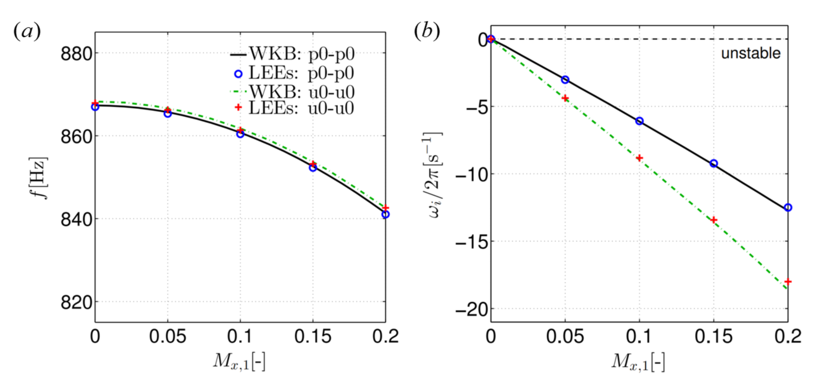
Figure 5 presents the evolution of the resonant frequency and growth rate as a function of the inlet flow Mach number M x , 1 . The analytical results calculated by the proposed solutions present good consistency with the results of the numerical LEEs. The growth rate is zero when the mean flow is stationary. With a baseline of no mean flow, the 1T mode becomes more unstable as the incoming flow Mach number increases, especially for the closed–closed ends.
These results show that the system with both mean temperature profile and mean flow presents different linear stabilities from that with either uniform mean temperature or no mean flow. The presence of mean temperature gradient and the mean flow lead to evident shifts of the resonant frequencies and growth rates. Therefore, both should be taken into account during predictions and simulations for sound propagation through a three-dimensional cylindrical duct.

6.3. Transverse Modes with Different Boundary Conditions

In addition to the 1T mode, the first radial mode and the second transverse mode were investigated in order to provide general verifications of the analytical solutions. With both kinds of boundary conditions, as presented in Table 2, analytical predictions of resonant frequencies and growth rates are in good agreement with the numerical LEE results in the case of M x , 1 = 0.1 and T ¯ 2 = 1200 K. High precision can be achieved by applying the proposed WKB-type solutions in the eigenvalue system. The convection wave generated by the acoustic waves propagating through the region of varying mean temperature and inhomogeneous mean flow results in a larger absolute value of the growth rate when a velocity-dependent boundary is prescribed.

7. Conclusions

In this work, we obtain an analytical solution for a three-dimensional acoustic field in a cylindrical duct in the presence of an axial temperature gradient and mean flow. This paper extends our previous works involving a one-dimensional straight duct [43] to a three-dimensional cylindrical duct. We first account for the multi-dimensional acoustic perturbations that propagate through the inhomogeneous field; both the axial mean temperature distribution and mean flow are present. A second-order partial differential wave equation is obtained from linearised Euler equations (LEEs) in the cylindrical system. Then, the separation of variables and a modified WKB method are applied to derive the analytical expressions of pressure and velocity perturbations when the high-frequency assumption | k 0 | | α | is satisfied. Based on the proposed analytical solutions, an eigenvalue system is built by providing boundary conditions of both duct ends and assuming zero vorticity perturbation at the inlet.
Validation is conducted by comparing the analytical solutions to the results of numerical LEEs. For a linear axial temperature profile, the proposed analytical solutions are applied to predict the acoustic perturbations in the cylindrical geometry for three transverse modes and two kinds of boundary conditions. The results show that the proposed analytical solutions can provide accurate predictions for the three-dimensional acoustic field and the thermoacoustic modes with both the temperature gradient and the mean flow considered. High precision is achieved when frequencies are larger than the cut-off frequency. Both axially varying mean temperature and mean flow can change the apparent growth rate within a thermoacoustic system. Therefore, the assumption of either no mean flow or zero temperature gradient should be used cautiously in the low order modeling of combustion systems.

Author Contributions

Conceptualization, J.N. and J.L.; methodology, J.N.; software, J.N.; validation, J.N.; formal analysis, J.N.; investigation, J.N.; writing—original draft, J.N.; writing—review and editing, J.L. and L.Y.; supervision, J.L. and L.Y.; project administration, J.L. and L.Y.; funding acquisition, J.L., L.Y. and J.N. All authors have read and agreed to the published version of the manuscript.

Funding

This research was funded by the Chinese National Natural Science Funds for National Natural Science Foundation of China grant number 51806006, 11927802 and National Major Science and Technology Projects of China grant number 2017-III-0004-0028. This work was supported by the Academic Excellence Foundation of BUAA for PhD Students.

Institutional Review Board Statement

Not applicable.

Informed Consent Statement

Not applicable.

Data Availability Statement

Not applicable.

Acknowledgments

We would like to express our thanks to the editors of Aerospace and the reviewers for their work in processing this article.

Conflicts of Interest

The authors declare no conflict of interest.

Nomenclature

clocal speed of sound
c p heat capacity at constant pressure
ffrequency
F transfer function
iimaginary unit, −i2=1
k 0 local wavenumber, ω / c ¯
lduct length
M x flow Mach number in the x direction
n r radial wavenumber
n θ circumferential wavenumber
ppressure
q ˙ heat flux
r 0 radius of the cylindrical duct
R g universal gas constant
sentropy
ttime
Ttemperature
u = ( u x , u r , u θ ) velocity vector in the cylindrical polar coordinates
x , r , θ cylindrical polar coordinates
ρ density
ω angular frequency
γ specific heat ratio
ξ vorticity, × u
Ω dimensionless frequency, Ω = f l / c ¯ 1
Ω c dimensionless cut-off frequency
( ) ¯ steady flow variable
( ) ^ spatial component of unsteady flow variable
( ) 1 flow property at the duct inlet
( ) 2 flow property at the duct outlet

References

  1. Yang, V.; Anderson, W.E. Liquid Rocket Engine Combustion Instability; AIAA, Inc.: Reston, VA, USA, 1995. [Google Scholar]
  2. Lieuwen, T.; Yang, V. Combustion Instabilities in Gas Turbine Engines: Operational Experience Fundamental Mechanisms and Modeling; AIAA, Inc.: Reston, VA, USA, 2005. [Google Scholar]
  3. Candel, S. Combustion dynamics and control: Progress and challenges. Proc. Combust. Inst. 2002, 29, 1–28. [Google Scholar] [CrossRef]
  4. Dowling, A.P.; Morgans, A.S. Feedback control of combustion oscillations. Annu. Rev. Fluid Mech. 2005, 37, 151–182. [Google Scholar] [CrossRef]
  5. Poinsot, T. Prediction and control of combustion instabilities in real engines. Proc. Combust. Inst. 2017, 36, 1–28. [Google Scholar] [CrossRef] [Green Version]
  6. Li, J.; Xia, Y.; Morgans, A.S.; Han, X. Numerical prediction of combustion instability limit cycle oscillations for a combustor with a long flame. Combust. Flame 2017, 185, 28–43. [Google Scholar] [CrossRef]
  7. Staffelbach, G.; Gicquel, L.; Boudier, G.; Poinsot, T. Large Eddy Simulation of self excited azimuthal modes in annular combustors. Proc. Combust. Inst. 2009, 32, 2909–2916. [Google Scholar] [CrossRef] [Green Version]
  8. Gicquel, L.; Staffelbach, G.; Poinsot, T. Large Eddy Simulations of gaseous flames in gas turbine combustion chambers. Prog. Energy Combust. Sci. 2012, 38, 782–817. [Google Scholar] [CrossRef] [Green Version]
  9. Urbano, A.; Selle, L.; Staffelbach, G.; Cuenot, B.; Schmitt, T.; Ducruix, S.; Candel, S. Exploration of combustion instability triggering using large eddy simulation of a multiple injector liquid rocket engine. Combust. Flame 2016, 169, 129–140. [Google Scholar] [CrossRef] [Green Version]
  10. Noiray, N.; Durox, D.; Schuller, T.; Cande, S. A unified framework for nonlinear combustion instability analysis based on the flame describing function. J. Fluid Mech. 2008, 615, 139–167. [Google Scholar] [CrossRef]
  11. Krediet, H.; Beck, C.; Krebs, W.; Kok, J. Saturation mechanism of the heat release response of a premixed swirl flame using LES. Proc. Combust. Inst. 2013, 34, 1223–1230. [Google Scholar] [CrossRef]
  12. Han, X.; Li, J.; Morgans, A.S. Prediction of combustion instability limit cycle oscillations by combining flame describing function simulations with a thermoacoustic network model. Combust. Flame 2015, 162, 3632–3647. [Google Scholar] [CrossRef]
  13. Schuller, T.; Poinsot, T.; Candel, S. Dynamics and control of premixed combustion systems based on flame transfer and describing functions. J. Fluid Mech. 2020, 894. [Google Scholar] [CrossRef]
  14. Polifke, W. Modeling and analysis of premixed flame dynamics by means of distributed time delays. Prog. Energy Combust. Sci. 2020, 79, 100845. [Google Scholar] [CrossRef]
  15. Polifke, W.; Poncet, A.; Paschereit, C.; Döbbeling, K. Reconstruction of acoustic transfer matrices by instationary computational fluid dynamics. J. Sound Vib. 2001, 245, 483–510. [Google Scholar] [CrossRef]
  16. Stow, S.R.; Dowling, A.P. A time-domain network model for nonlinear thermoacoustic oscillations. J. Eng. Gas Turbines Power 2009, 131, 031502. [Google Scholar] [CrossRef]
  17. Bauerheim, M.; Parmentier, J.F.; Salas, P.; Nicoud, F.; Poinsot, T. An analytical model for azimuthal thermoacoustic modes in an annular chamber fed by an annular plenum. Combust. Flame 2014, 161, 1374–1389. [Google Scholar] [CrossRef] [Green Version]
  18. Li, J.; Morgans, A.S. Time domain simulations of nonlinear thermoacoustic behaviour in a simple combustor using a wave-based approach. J. Sound Vib. 2015, 346, 345–360. [Google Scholar] [CrossRef] [Green Version]
  19. Yang, D.; Morgans, A.S. Acoustic Models for Cooled Helmholtz Resonators. AIAA J. 2017, 55, 3120–3127. [Google Scholar] [CrossRef] [Green Version]
  20. Li, C.; Yang, D.; Li, S.; Zhu, M. An analytical study of the effect of flame response to simultaneous axial and transverse perturbations on azimuthal thermoacoustic modes in annular combustors. Proc. Combust. Inst. 2019, 37, 5279–5287. [Google Scholar] [CrossRef]
  21. Laurent, C.; Badhe, A.; Nicoud, F. Representing the geometrical complexity of liners and boundaries in low-order modeling for thermoacoustic instabilities. J. Comput. Phys. 2021, 428, 110077. [Google Scholar] [CrossRef]
  22. Li, L.; Sun, X. Effect of vorticity waves on azimuthal instabilities in annular chambers. Combust. Flame 2015, 162, 628–641. [Google Scholar] [CrossRef]
  23. Schulze, M.; Sattelmayer, T. Linear stability assessment of a cryogenic rocket engine. Int. J. Spray Combust. Dyn. 2017, 9, 277–298. [Google Scholar] [CrossRef] [Green Version]
  24. Meindl, M.; Silva, C.F.; Polifke, W. On the spurious entropy generation encountered in hybrid linear thermoacoustic models. Combust. Flame 2021, 223, 525–540. [Google Scholar] [CrossRef]
  25. Zhao, D. Transient growth of flow disturbances in triggering a Rijke tube combustion instability. Combust. Flame 2012, 159, 2126–2137. [Google Scholar] [CrossRef]
  26. Kashinath, K.; Hemchandra, S.; Juniper, M.P. Nonlinear thermoacoustics of ducted premixed flames: The influence of perturbation convection speed. Combust. Flame 2013, 160, 2856–2865. [Google Scholar] [CrossRef]
  27. Meindl, M.; Albayrak, A.; Polifke, W. A state-space formulation of a discontinuous galerkin method for thermoacoustic stability analysis. J. Sound Vib. 2021, 481, 115431. [Google Scholar] [CrossRef]
  28. Silva, C.F.; Nicoud, F.; Schuller, T.; Durox, D.; Candel, S. Combining a helmholtz solver with the flame describing function to assess combustion instability in a premixed swirled combustor. Combust. Flame 2013, 160, 1743–1754. [Google Scholar] [CrossRef] [Green Version]
  29. Laera, D.; Camporeale, S.M. A Weakly Nonlinear Approach Based on a Distributed Flame Describing Function to Study the Combustion Dynamics of a Full-Scale Lean-Premixed Swirled Burner. J. Eng. Gas Turbines Power 2017, 139, 091501. [Google Scholar] [CrossRef]
  30. Schuermans, B. Modeling and Control of Thermoacoustic Instabilities. Ph.D. Thesis, École Polytechnique Fédérale de Lausanne, Lausanne, Switzerland, 2003. [Google Scholar]
  31. Li, J.; Yang, D.; Luzzato, C.; Morgans, A.S. OSCILOS: The Open Source Combustion Instability Low Order Simulator. Technical Report. Imperial College London. 2014. Available online: http://www.oscilos.com (accessed on 26 July 2021).
  32. You, D.; Ku, D.D.; Yang, V. Acoustic waves in baffled combustion chamber with radial and circumferential blades. J. Propul. Power 2013, 29, 1453–1467. [Google Scholar] [CrossRef] [Green Version]
  33. Dowling, A.P.; Stow, S.R. Acoustic analysis of gas turbine combustors. J. Propul. Power 2003, 19, 751–764. [Google Scholar] [CrossRef]
  34. Schuermans, B.; Guethe, F.; Pennell, D.; Guyot, D.; Paschereit, C.O. Thermoacoustic Modeling of a Gas Turbine Using Transfer Functions Measured Under Full Engine Pressure. J. Eng. Gas Turbines Power 2010, 132, 111503. [Google Scholar]
  35. Poinsot, T.; Veynante, D. Theoretical and Numerical Combustion; R.T. Edwards Inc.: Philadelphia, PA, USA, 2005. [Google Scholar]
  36. Palies, P.; Durox, D.; Schuller, T.; Candel, S. Nonlinear combustion instability analysis based on the flame describing function applied to turbulent premixed swirling flames. Combust. Flame 2011, 158, 1980–1991. [Google Scholar] [CrossRef]
  37. Orchini, A.; Juniper, M.P. Flame double input describing function analysis. Combust. Flame 2016, 171, 87–102. [Google Scholar] [CrossRef] [Green Version]
  38. Morgans, A.; Stow, S. Model-based control of combustion instabilities in annular combustors. Combust. Flame 2007, 150, 380–399. [Google Scholar] [CrossRef]
  39. Schmitt, P.; Poinsot, T.; Schuermans, B.; Geigle, K.P. Large-eddy simulation and experimental study of heat transfer, nitric oxide emissions and combustion instability in a swirled turbulent high-pressure burner. J. Fluid Mech. 2007, 570, 17–46. [Google Scholar] [CrossRef] [Green Version]
  40. Kim, K.; Lee, J.; Quay, B.; Santavicca, D. Spatially distributed flame transfer functions for predicting combustion dynamics in lean premixed gas turbine combustors. Combust. Flame 2010, 157, 1718–1730. [Google Scholar] [CrossRef]
  41. Heinig, K. Sounding propagation in multistage axial flow turbomachines. AIAA J. 1983, 21, 98–105. [Google Scholar] [CrossRef]
  42. Nicoud, F.; Wieczorek, K. About the zero Mach number assumption in the calculation of thermoacoustic instability. Int. J. Spray Combust. Dyn. 2009, 101, 67–111. [Google Scholar] [CrossRef] [Green Version]
  43. Li, J.; Morgans, A.S. The one-dimensional acoustic field in a duct with arbitrary mean axial temperature gradient and mean flow. J. Sound Vib. 2017, 400, 248–269. [Google Scholar] [CrossRef]
  44. Marble, F.E.; Candel, S.M. Acoustic disturbance from gas non-uniformities convected through a nozzle. J. Sound Vib. 1977, 55, 225–243. [Google Scholar] [CrossRef]
  45. Rienstra, S.; Hirschberg, A. An Introduction to Acoustics; Eindhoven University of Technology: Eindhoven, The Netherlands, 2016. [Google Scholar]
  46. Lieuwen, T. Unsteady Combustor Physics; Cambridge University Press: Cambridge, UK, 2012. [Google Scholar]
  47. Sujith, R.; Waldherr, G.; Zinn, B. An exact solution for one-dimensional acoustic fields in ducts with an axial temperature gradient. J. Sound Vib. 1995, 184, 389–402. [Google Scholar] [CrossRef]
  48. Duran, I.; Moreau, S. Solution of the quasi-one-dimensional linearized Euler equations using flow invariants and the Magnus expansion. J. Fluid Mech. 2013, 723, 190–231. [Google Scholar] [CrossRef]
  49. Duran, I.; Morgans, A. On the reflection and transmission of circumferential waves through nozzles. J. Fluid Mech. 2015, 773, 137–153. [Google Scholar] [CrossRef] [Green Version]
  50. Peat, K. The transfer matrix of a uniform duct with a linear temperature gradient. J. Sound Vib. 1988, 123, 43–53. [Google Scholar] [CrossRef]
  51. Cummings, A. Ducts with axial temperature gradients: An approximate solution for sound transmission and generation. J. Sound Vib. 1977, 51, 55–67. [Google Scholar] [CrossRef]
  52. Sirignano, W.A.; Popov, P.P. Two-dimensional model for liquid-rocket transverse combustion instability. AIAA J. 2013, 51, 2919–2934. [Google Scholar] [CrossRef] [Green Version]
  53. Li, J.; Nan, J.; Yang, L. Analytical solutions for the acoustic field in a thin annular duct with temperature gradient and mean flow. J. Sound Vib. 2020, 467, 115043. [Google Scholar] [CrossRef]
  54. Li, J.; Morgans, A.S.; Yang, L. The three-dimensional acoustic field in cylindrical and annular ducts with an axially varying mean temperature. Aerosp. Sci. Technol. 2020, 99, 105712. [Google Scholar] [CrossRef]
  55. Karimi, N.; Brear, M.J.; Moase, W.H. Acoustic and disturbance energy analysis of a flow with heat communication. J. Fluid Mech. 2008, 597, 67–89. [Google Scholar] [CrossRef]
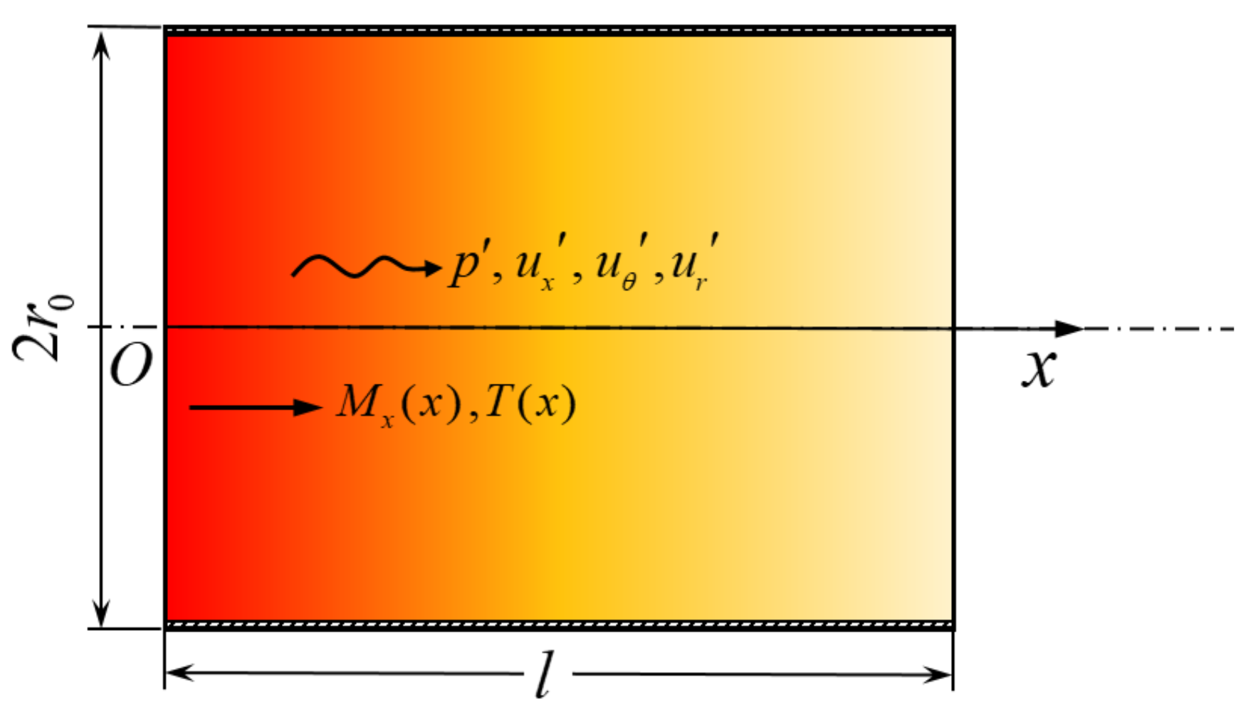
Figure 1. Sketch of a cylindrical duct containing an axial temperature profile T ( x ) and mean flow M x ( x ) .
Aerospace 09 00588 g001
Figure 2. 1T mode: Contour comparisons for the real part of (a) pressure F p and (b) axial velocity F u x transfer functions on the π / 2 plane. Ω = 0.8 , M x , 1 = 0.20 .
Aerospace 09 00588 g002
Figure 3. 1T mode: variations of (a) pressure F p and (b) axial velocity F u x transfer functions along axial positions. ( r , θ ) = ( r 0 / 2 , π / 2 ) , M x , 1 = 0.20 .
Aerospace 09 00588 g003
Figure 4. Variation of the first transverse (1T) mode as a function of the outlet mean temperature for the open–open ends (p0-p0) and the closed–closed ends (u0-u0): (a) resonant frequencies and (b) growth rates. T ¯ 1 = 1600 K , M x , 1 = 0.10 .
Aerospace 09 00588 g004
Figure 5. Variation of the first transverse (1T) mode with the incoming flow Mach number for the open–open ends and the closed–closed ends: (a) resonant frequencies and (b) growth rates. T ¯ 1 = 1600 K , T ¯ 2 = 1200 K .
Aerospace 09 00588 g005
Table 1. Parameters fixed in the analyses.
l [m] r 0 [m] x 1 [m] p ¯ 1 [Pa] T ¯ 1 [K] T ¯ 2 [K] γ [-] R g [J K 1 kg−1]
0.50.501× 10 5 160012001.4287
Table 2. Predicted resonant frequencies for the three transverse modes with different boundary conditions.
Open-Open EndsClosed-Closed Ends
f [Hz]WKBLEEs | Δ f / f LEEs | WKBLEEs | Δ f / f LEEs |
1T1L860.77860.420.041%861.65861.350.035%
1R1L1174.181172.600.135%1178.641176.500.182%
2T1L1037.321036.300.098%1039.661038.400.121%
ω i / 2 π [ s 1 ]WKBLEEs | Δ ω i / ω i LEEs | WKBLEEs | Δ ω i / ω i LEEs |
1T1L−6.1275−6.08130.760%−8.9604−8.82451.540%
1R1L−3.9789−3.88392.446%−12.653−12.3922.106%
2T1L−4.6951−4.60002.067%−10.918−10.7391.667%
Publisher’s Note: MDPI stays neutral with regard to jurisdictional claims in published maps and institutional affiliations.