

Study on Flow and Heat Transfer Performance of a Rectangular Channel Filled with X-Shaped Truss Array under Operating Conditions of Gas Turbine Blades


Abstract
:1. Introduction
2. Research Object
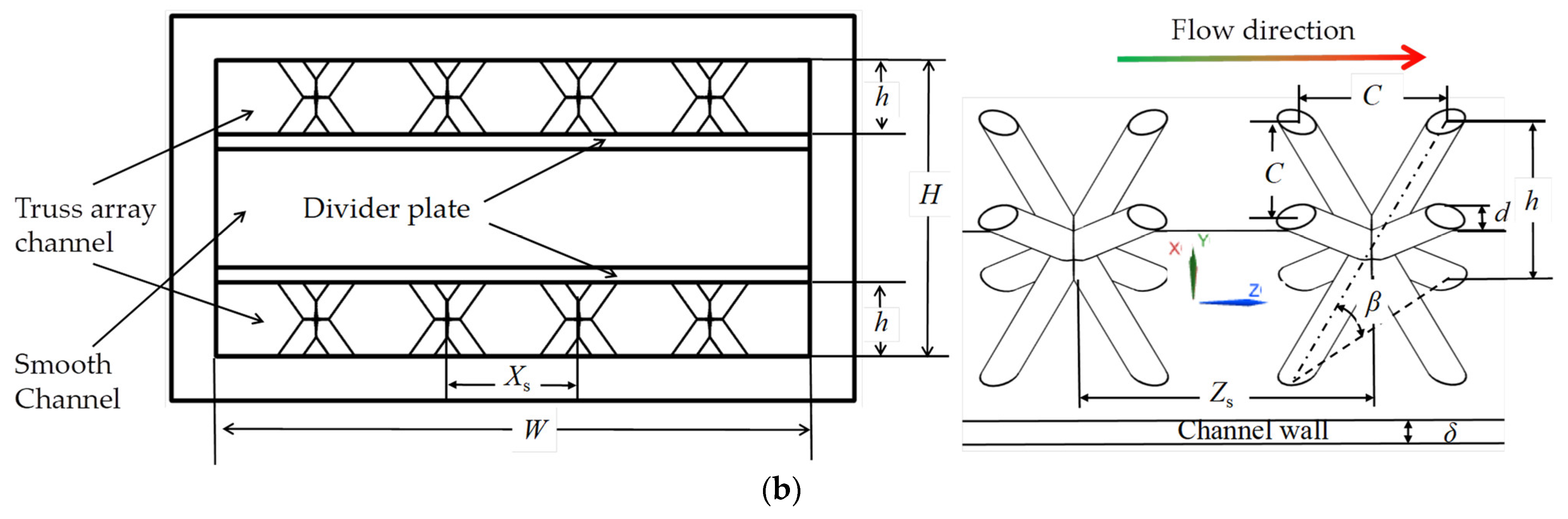
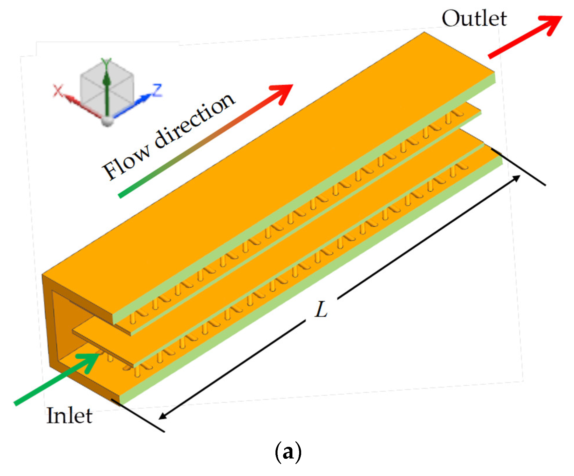
2.1. Physical Model
2.2. Data Reduction
3. Numerical Simulation Approach
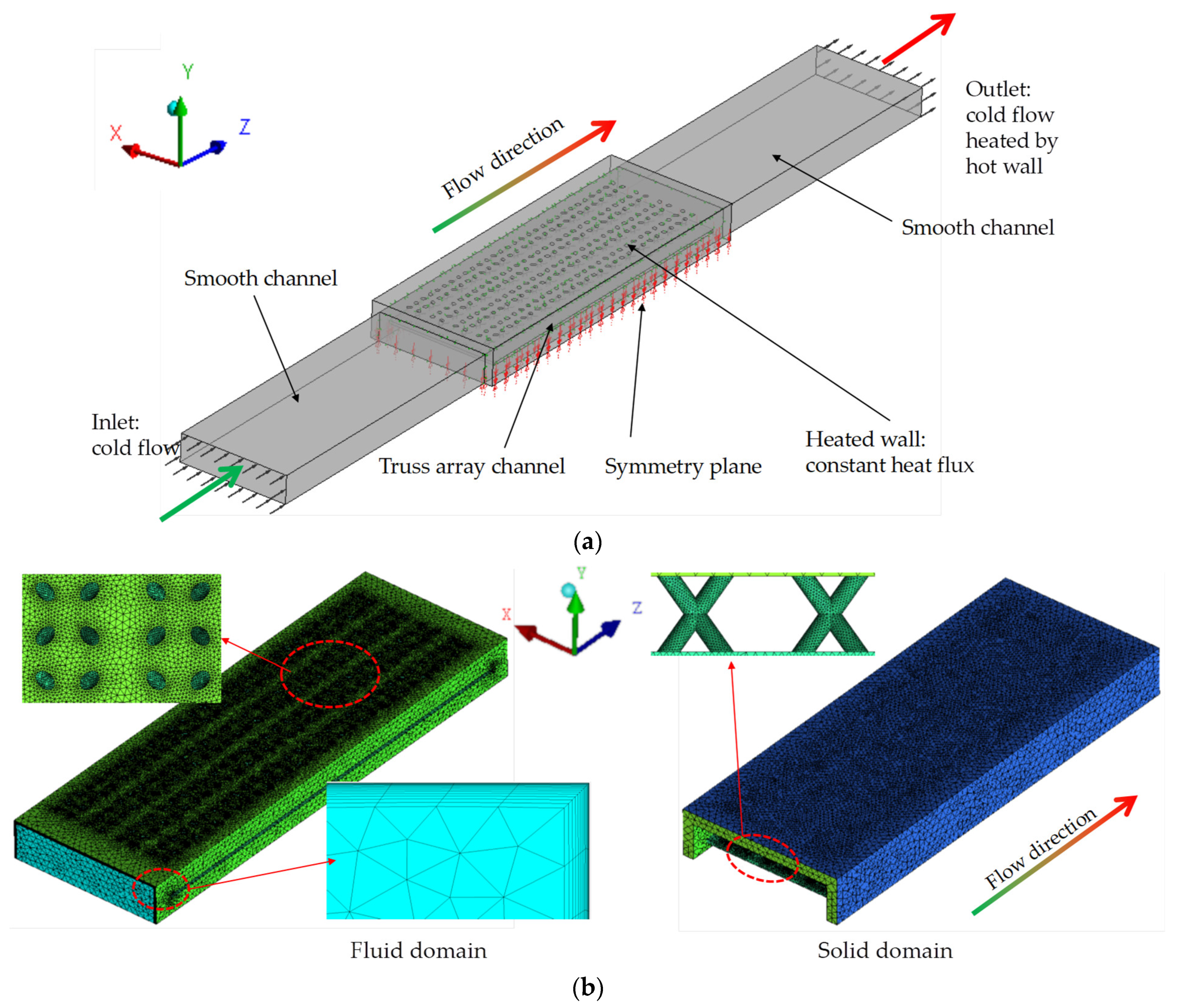
3.1. Numerical Simulation Model
3.2. Numerical Calculation Methods
3.3. Boundary Conditions
3.4. Numerical Method Verification
4. Results Analysis and Discussion
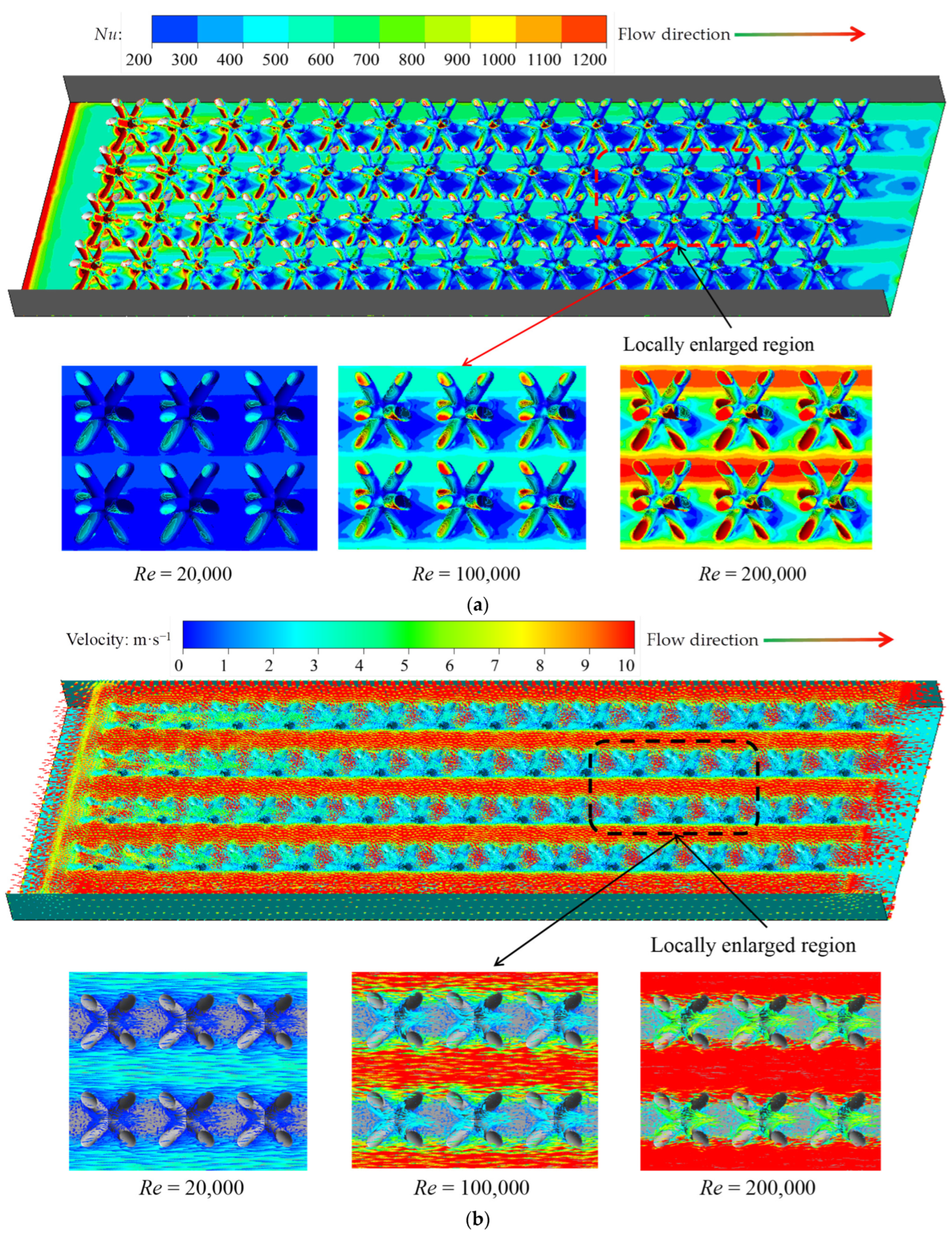
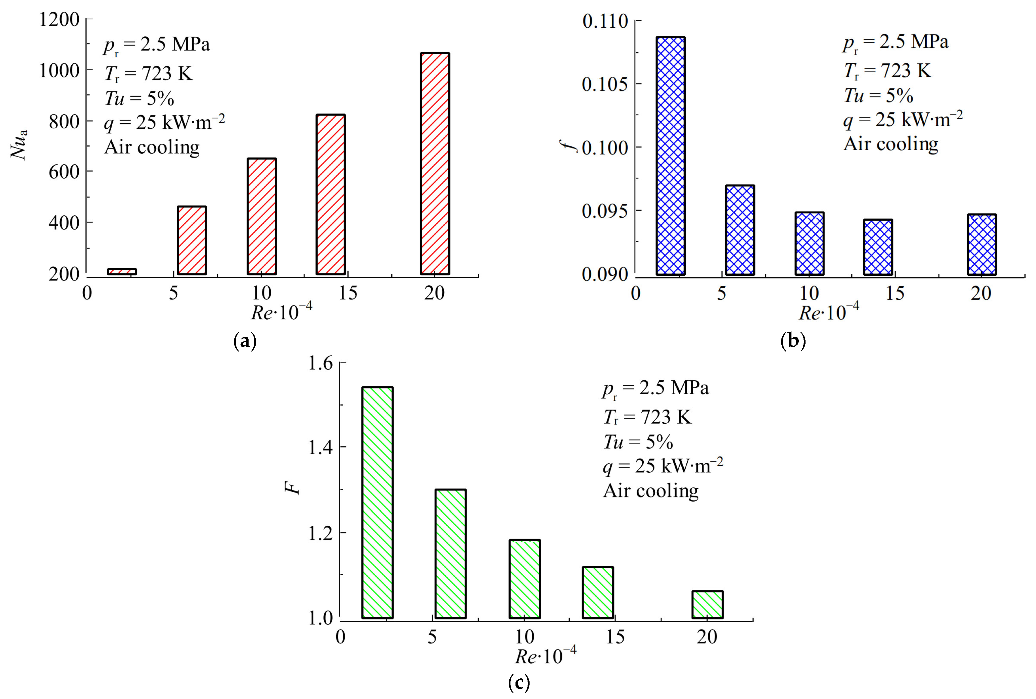
4.1. Effects of Inlet Reynolds Number
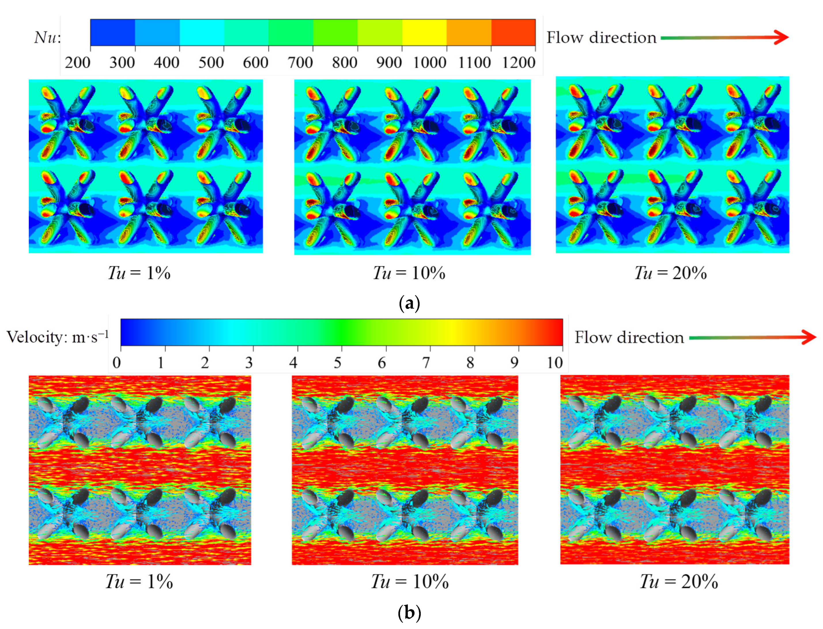
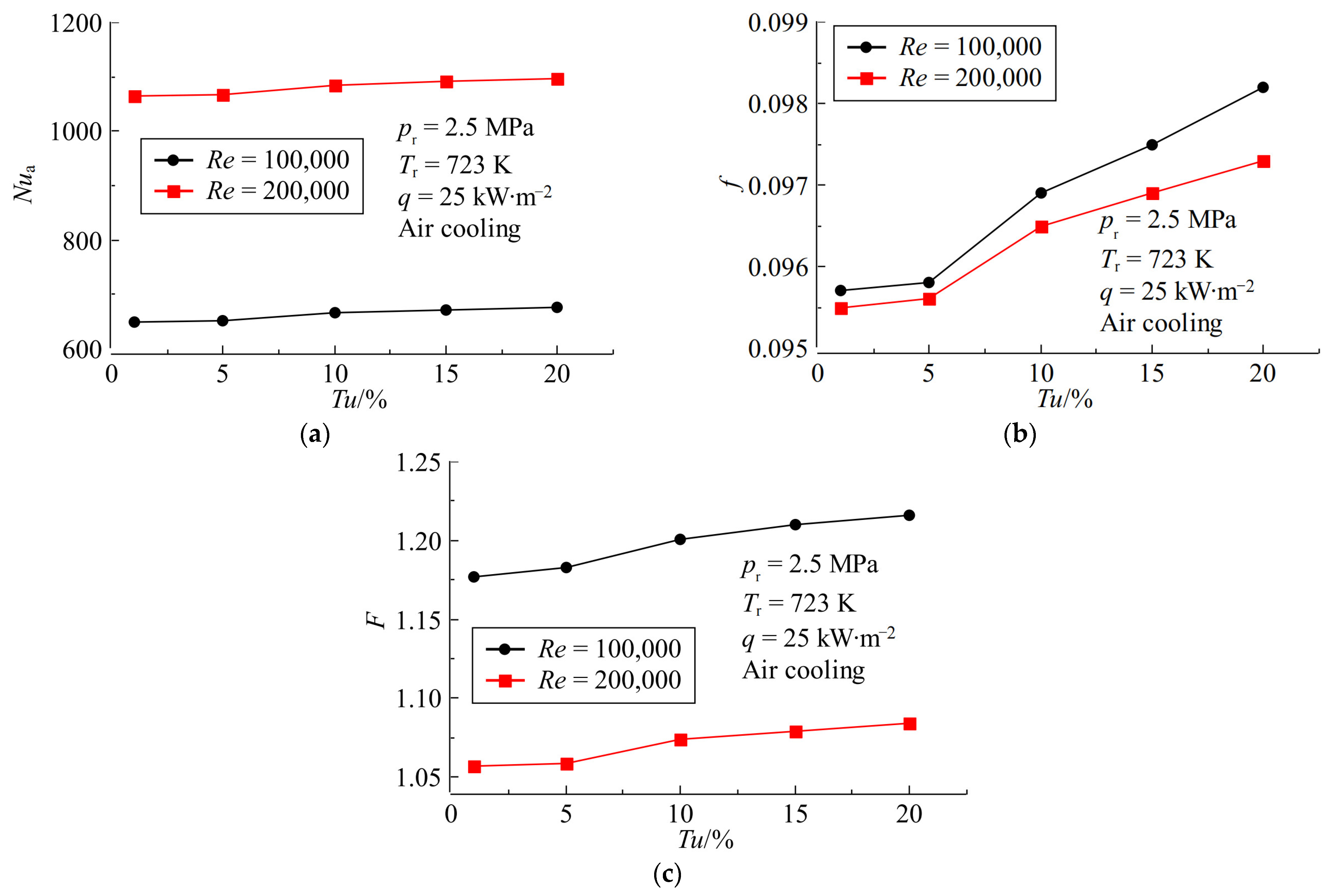
4.2. Effects of Inlet Turbulence Intensity
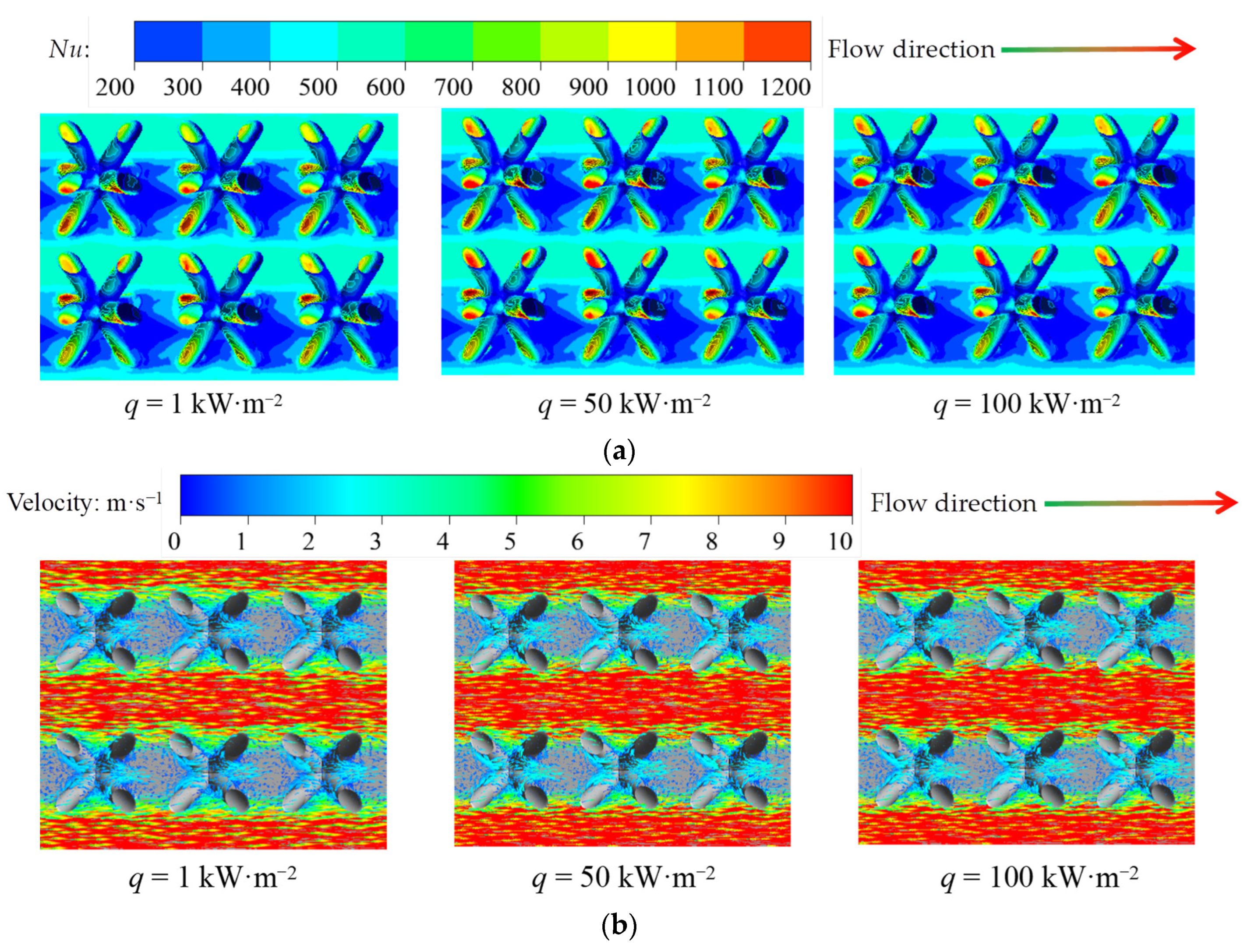
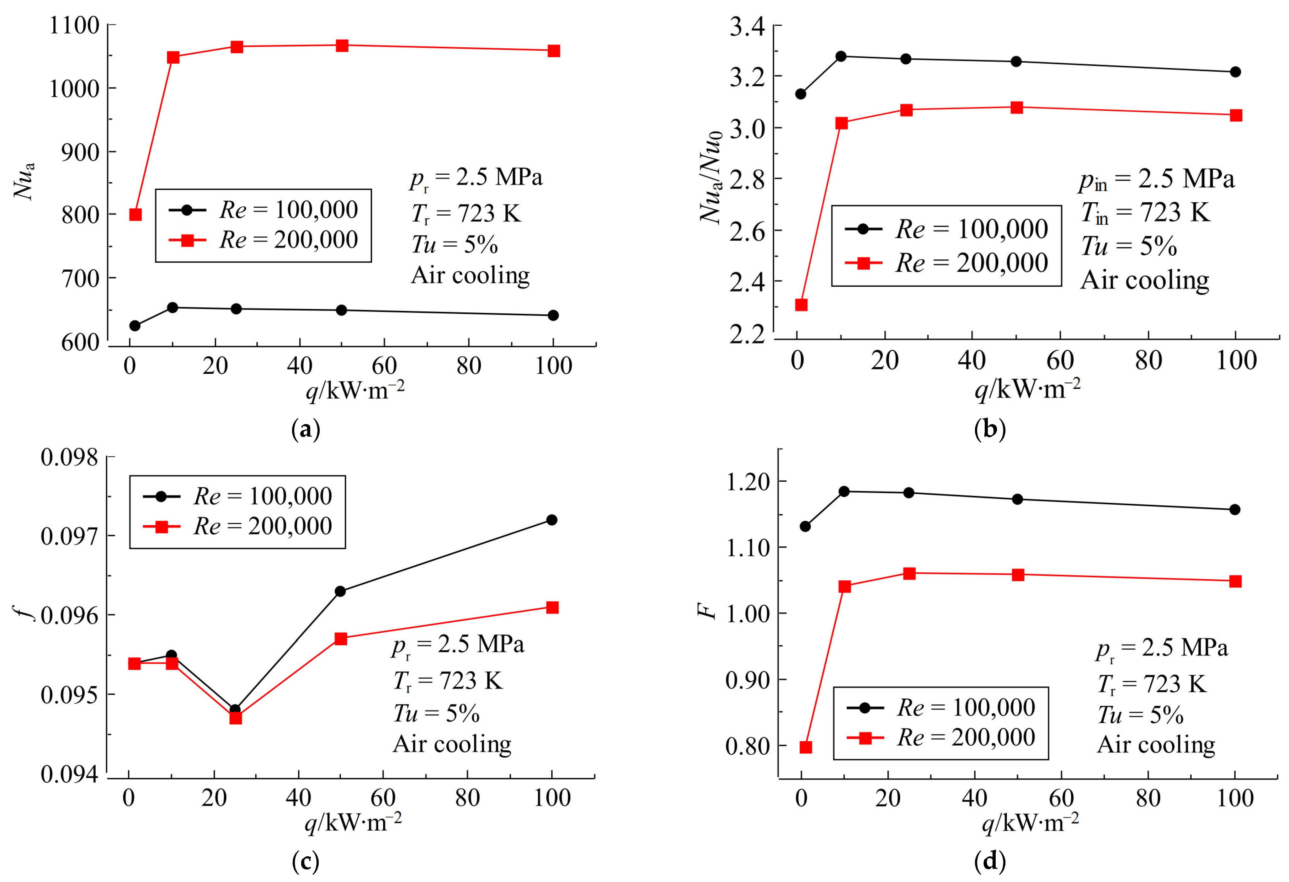
4.3. Effects of Wall Heat Flux
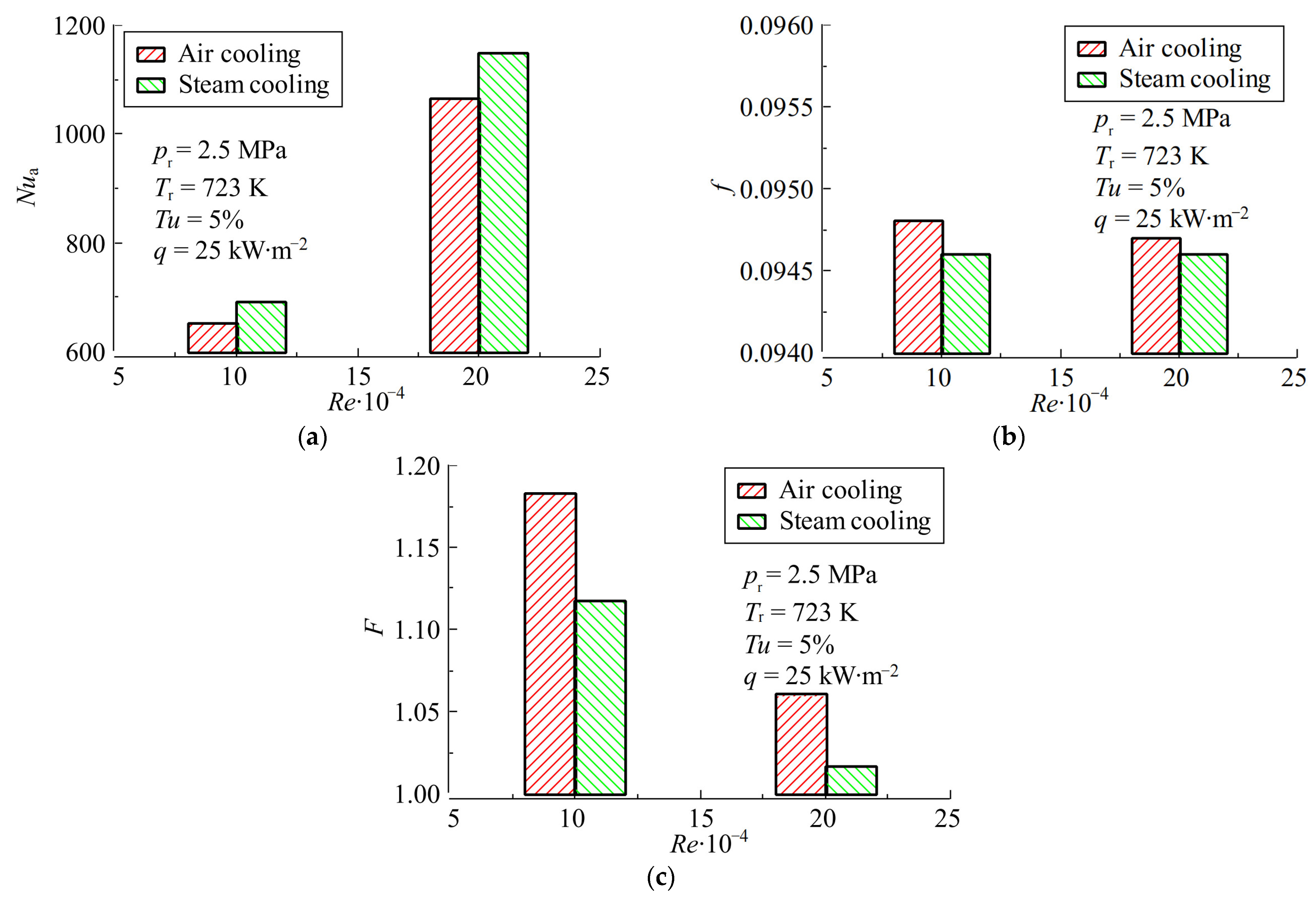
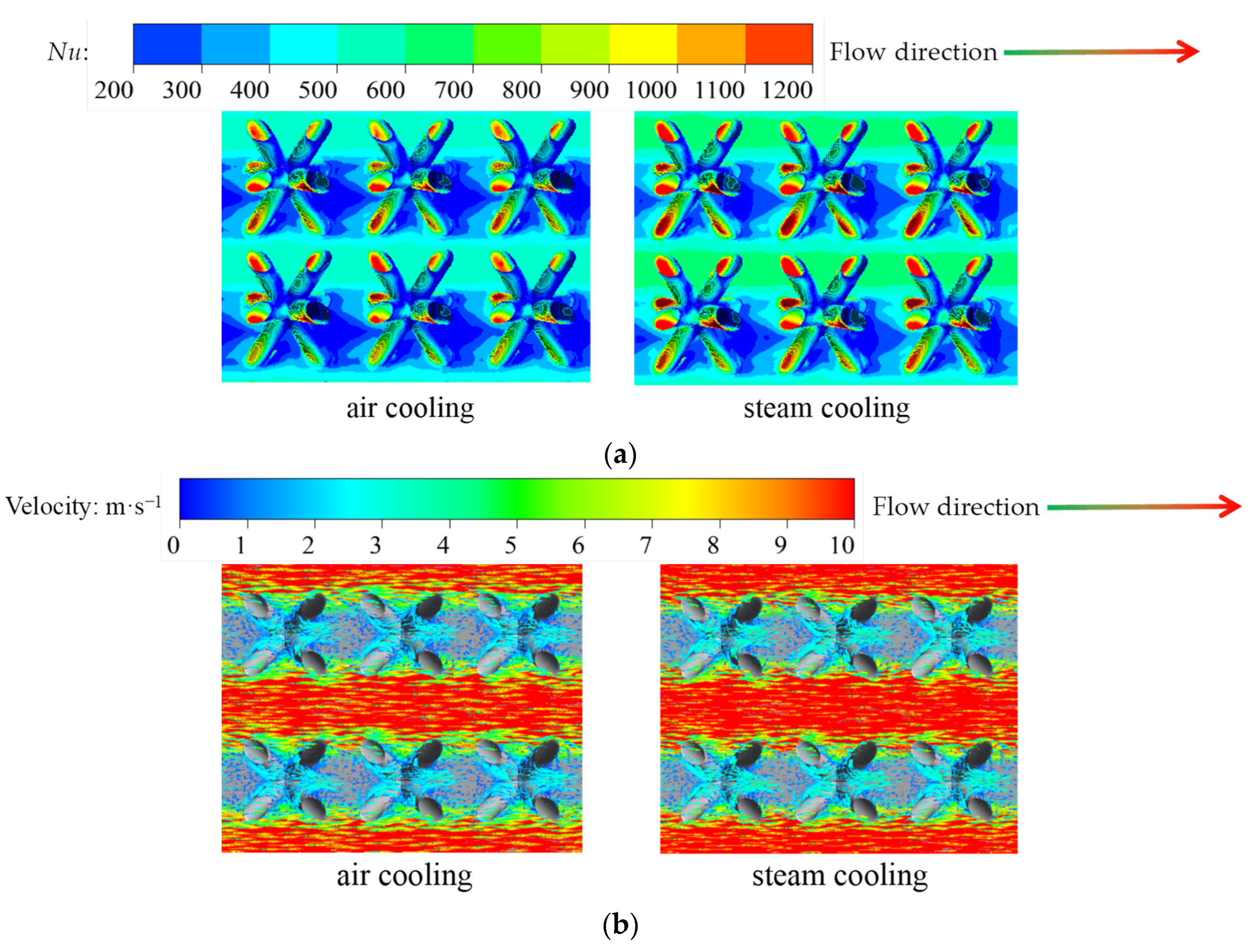
4.4. Comparison of Air Cooling and Steam Cooling
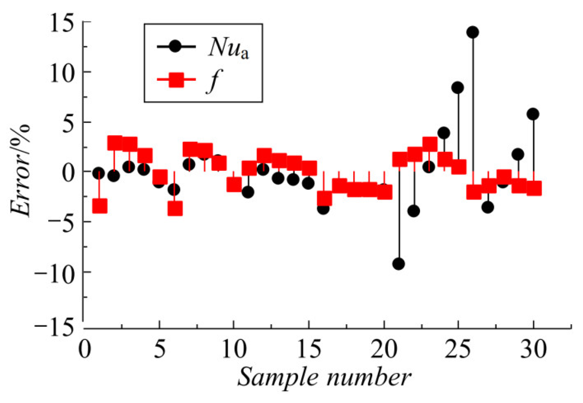
4.5. Empirical Correlations
5. Conclusions
- (1)
- Among the three parameters of inlet Re, inlet Tu and q, the inlet Re has the most significant effect on the flow and heat transfer performance of the XTA channel.
- (2)
- When the inlet Re increases from 20,000 to 200,000, the Nua of the XTA channel is increased by 3.92 times, the f is decreased by 12.88% and the F is decreased by 31.19%.
- (3)
- Compared with the medium turbulence intensity (Tu = 5%), the Nua, f and F of the XTA channel at Tu = 20% are increased by 3.70%, 2.51% and 2.79%, respectively.
- (4)
- With the increase in the q, the f of the XTA channel roughly shows a trend of first decreasing and then increasing, while the Nua and the F show a trend of first rapidly increasing and then slightly decreasing or remaining unchanged.
- (5)
- Compared with air cooling, the Nua of the XTA channel of steam cooling are increased by 6.30% to 9.54%, and the corresponding f and F are decreased by 0.11% to 0.55% and 2.63% to 5.59%, respectively.
- (6)
- The empirical correlations of Nua and f for the XTA cooling channel under different operating conditions were fitted; the corresponding maximum fitting deviations are within ± 14%.
Author Contributions
Funding
Data Availability Statement
Conflicts of Interest
Nomenclature
| C | Characteristic length of the truss element, mm. |
| D | Diameter of the truss rod, mm. |
| F | Friction coefficient of the XTA channel. |
| f0 | Friction coefficient of the smooth channel. |
| F | Comprehensive thermal coefficient. |
| H | Height of the subchannel near the wall, mm. |
| H | Height of the channel, mm. |
| L | Length of the channel, mm. |
| Nu | Local Nusselt number of the XTA channel. |
| Nua | Average Nusselt number of the XTA channel. |
| Nu0 | Average Nusselt number of the smooth channel. |
| pr | Reference pressure of the cooling medium, Pa. |
| Pr | Prandtl number. |
| q | Local wall heat flux, W·m−2. |
| Qmax | Maximum heat flux in this study, W·m−2. |
| Re | Inlet Reynolds number. |
| Tc | Local bulk fluid temperature, K. |
| Tr | Reference temperature of the cooling medium, Pa. |
| Tw | Local wall temperature, K. |
| Tu | Inlet turbulence intensity, %. |
| U | Inlet velocity of the cooling medium, m·s−1. |
| W | Width of the channel, mm. |
| Xs | Transverse spacing of adjacent truss elements, mm. |
| Zs | Streamwise spacing of adjacent truss elements, mm. |
| Greek symbols | |
| β | Truss rod inclination angle, °. |
| δ | Wall thickness of the channel, mm. |
| Δp | Pressure drop across the channel, Pa. |
| λ | Heat conductivity of the cooling medium, W·m−1·K−1. |
| ρ | Density of the cooling medium, kg·m−3. |
| Υ | Kinematic viscosity of the cooling medium, m2·s−1. |
References
- Wang, Q.; Yang, L.; Huang, K. Fast prediction and sensitivity analysis of gas turbine cooling performance using supervised learning approaches. Energy 2022, 246, 123373. [Google Scholar] [CrossRef]
- Xi, L.; Gao, J.; Xu, L.; Zhao, Z.; Ruan, Q.; Li, Y. Numerical investigation and parameter sensitivity analysis on flow and heat transfer performance of jet array impingement cooling in a quasi-leading-edge channel. Aerospace 2022, 9, 87. [Google Scholar] [CrossRef]
- Anwajler, B. The thermal properties of a prototype insulation with a gyroid structure—optimization of the structure of a cellular composite made using SLS printing technology. Materials 2022, 15, 1352. [Google Scholar] [CrossRef] [PubMed]
- Li, S.; Jiang, W.; Zhu, X.; Xie, X. Effect of localized defects on mechanical and creep properties for pyramidal lattice truss panel structure by analytical, experimental and finite element methods. Thin Wall. Struct. 2022, 170, 108531. [Google Scholar] [CrossRef]
- Park, K.-M.; Min, K.-S.; Roh, Y.-S. Design optimization of lattice structures under compression: Study of unit cell types and cell arrangements. Materials 2022, 15, 97. [Google Scholar] [CrossRef] [PubMed]
- Ho, J.Y.; Leong, K.C.; Wong, T.N. Experimental and numerical investigation of forced convection heat transfer in porous lattice structures produced by selective laser melting. Int. J. Therm. Sci. 2019, 137, 276–287. [Google Scholar] [CrossRef]
- Ho, J.Y.; Leong, K.C.; Wong, T.N. Additively-manufactured metallic porous lattice heat exchangers for air-side heat transfer enhancement. Int. J. Heat Mass Transf. 2020, 150, 119262. [Google Scholar] [CrossRef]
- Chen, Y.; Nassar, H.; Huang, G. Discrete transformation elasticity: An approach to design lattice-based polar metamaterials. Int. J. Eng. Sci. 2021, 168, 103562. [Google Scholar] [CrossRef]
- Zhang, Q.; Han, Y.; Chen, C.; Lu, T. Ultralight X-type lattice sandwich structure (I): Concept, fabrication and experimental characterization. Sci. China Ser. E 2009, 52, 2147–2154. [Google Scholar] [CrossRef]
- Al-Ketan, O.; Lee, D.W.; Rowshan, R.; Al-Rub, R.K.A. Functionally graded and multi-morphology sheet TPMS lattices: Design, manufacturing, and mechanical properties. J. Mech. Behav. Biomed. 2020, 102, 103520. [Google Scholar] [CrossRef] [PubMed]
- Plessis, A.D.; Razavi, S.M.J.; Benedetti, M.; Murchio, S.; Leary, M.; Watson, M.; Berto, F. Properties and applications of additively manufactured metallic cellular materials: A review. Prog. Mater. Sci. 2021, 125, 100918. [Google Scholar] [CrossRef]
- Kladovasilakis, N.; Charalampous, P.; Tsongas, K.; Kostavelis, I.; Tzetzis, D.; Tzovaras, D. Experimental and computational investigation of lattice sandwich structures constructed by additive manufacturing technologies. J. Manuf. Mater. Process. 2021, 5, 95. [Google Scholar] [CrossRef]
- Joo, J.H.; Kang, K.J.; Kim, T.; Lu, T.J. Forced convective heat transfer in all metallic wire-woven bulk Kagome sandwich panels. Int. J. Heat Mass Transf. 2011, 54, 5658–5662. [Google Scholar] [CrossRef]
- Ullah, I.; Elambasseril, J.; Brandt, M.; Feih, S. Performance of bio-inspired Kagome truss core structures under compression and shear loading. Compos. Struct. 2014, 118, 294–302. [Google Scholar] [CrossRef]
- Yan, H.B.; Zhang, Q.C.; Lu, T.J. Heat transfer enhancement by X-type lattice in ventilated brake disc. Int. J. Therm. Sci. 2016, 107, 39–55. [Google Scholar] [CrossRef]
- Akzhigitov, D.; Srymbetov, T.; Aldabergen, A.; Spitas, C. Structural and Aerodynamical Parametric Study of Truss-Core Gas Turbine Rotor Blade. J. Appl. Comput. Mech. 2021, 7, 831–838. [Google Scholar] [CrossRef]
- Yang, G.; Hou, C.; Zhao, M.; Mao, W. Comparison of convective heat transfer for kagome and tetrahedral truss-cored lattice sandwich panels. Sci. Rep. 2019, 9, 3731. [Google Scholar] [CrossRef]
- Kemerli, U.; Kahveci, K. Conjugate forced convective heat transfer in a sandwich panel with a kagome truss core: The effects of strut length and diameter. Appl. Therm. Eng. 2020, 167, 114794. [Google Scholar] [CrossRef]
- Ma, Y.; Yan, H.; Hooman, K.; Xie, G. Enhanced heat transfer in a pyramidal lattice sandwich panel by introducing pin-fins/protrusions/dimples. Int. J. Therm. Sci. 2020, 156, 106468. [Google Scholar] [CrossRef]
- Deb, D.; Rajan, H.; Kundu, R.; Mohan, R. CFD and machine learning based simulation of flow and heat transfer characteristics of micro lattice structures. IOP Conf. Ser. Earth Environ. Sci. 2021, 850, 012034. [Google Scholar] [CrossRef]
- Lai, X.; Wang, C.; Peng, D.; Yang, H.; Wei, Z. Analysis of heat transfer characteristics of a heat exchanger based on a lattice filling. Coatings 2021, 11, 1089. [Google Scholar] [CrossRef]
- Righetti, G.; Longo, G.A.; Mancin, S.; Zilio, C. Shape optimization of lattice-frame materials obtained via additive manufacturing during air forced convection. Exp. Heat Transf. 2022, 35, 1–16. [Google Scholar] [CrossRef]
- Caket, A.G.; Wang, C.; Nugroho, M.A.; Celik, H.; Mobedi, M. Recent studies on 3D lattice metal frame technique for enhancement of heat transfer: Discovering trends and reasons. Renew. Sust. Energ. Rev. 2022, 167, 112697. [Google Scholar] [CrossRef]
- Bai, X.; Liu, C.; Zhang, C.; Meng, X.; Li, J.; Zhang, X. A comprehensive study on the heat transfer characteristics of windward bend lattice frame structure. Propuls. Power Res. 2022, 11, 1–15. [Google Scholar] [CrossRef]
- Aider, Y.; Kaur, I.; Cho, H.; Singh, P. Periodic heat transfer characteristics of additively manufactured lattices. Int. J. Heat Mass Transf. 2022, 189, 122692. [Google Scholar] [CrossRef]
- Shahrzadi, M.; Emami, M.D.; Akbarzadeh, A.H. Heat transfer in BCC lattice materials: Conduction, convection, and radiation. Compos. Struct. 2022, 284, 115159. [Google Scholar] [CrossRef]
- Kaur, I.; Singh, P. Conjugate heat transfer in lattice frame materials based on novel unit cell topologies. Numer. Heat Transf. A-Appl. 2022, 82, 1–14. [Google Scholar] [CrossRef]
- Kaur, I.; Singh, P. Direct pore-scale simulations of fully periodic unit cells of different regular lattices. J. Heat Trans.-T. ASME 2022, 144, 022702. [Google Scholar] [CrossRef]
- Alkebsi, E.A.A.; Ameddah, H.; Outtas, T.; Almutawakel, A. Design of graded lattice structures in turbine blades using topology optimization. Int. J. Comput. Integr. M. 2021, 34, 370–384. [Google Scholar] [CrossRef]
- Hussain, S.; Ghopa, W.A.W.; Singh, S.S.K.; Azman, A.H.; Abdullah, S. Experimental and numerical vibration analysis of octet-truss-lattice-based gas turbine blades. Metals 2022, 12, 340. [Google Scholar] [CrossRef]
- Shen, B.; Li, Y.; Yan, H.; Boetcher, S.K.; Xie, G. Heat transfer enhancement of wedge-shaped channels by replacing pin fins with kagome lattice structures. Int. J. Heat Mass Transf. 2019, 141, 88–101. [Google Scholar] [CrossRef]
- Xu, L.; Ruan, Q.; Shen, Q.; Xi, L.; Gao, J.; Li, Y. Optimization design of lattice structures in internal cooling channel with variable aspect ratio of gas turbine blade. Energies 2021, 14, 3954. [Google Scholar] [CrossRef]
- Xu, L.; Shen, Q.; Ruan, Q.; Xi, L.; Gao, J.; Li, Y. Optimization design of lattice structures in internal cooling channel of turbine blade. Appl. Sci. 2021, 11, 5838. [Google Scholar] [CrossRef]
- Kaur, I.; Aider, Y.; Nithyanandam, K.; Singh, P. Thermal-hydraulic performance of additively manufactured lattices for gas turbine blade trailing edge cooling. Appl. Therm. Eng. 2022, 211, 118461. [Google Scholar] [CrossRef]
- Liang, D.; He, G.; Chen, W.; Chen, Y.; Chyu, M.K. Fluid flow and heat transfer performance for micro-lattice structures fabricated by Selective Laser Melting. Int. J. Therm. Sci. 2022, 172, 107312. [Google Scholar] [CrossRef]
- Fu, Q.; Luo, X.; Chen, W.; Chyu, M.K. Numerical investigation of the effects of lattice array structures on film cooling performance. Energies 2022, 15, 4711. [Google Scholar] [CrossRef]
- Xi, L.; Xu, L.; Gao, J.; Zhao, Z.; Li, Y. Study on flow and heat transfer performance of X-type truss array cooling channel. Case Stud. Therm. Eng. 2021, 26, 101034. [Google Scholar] [CrossRef]
- Xi, L.; Xu, L.; Gao, J.; Zhao, Z.; Li, Y. Cooling performance analysis and structural parameter optimization of X-shaped truss array channel based on neural networks and genetic algorithm. Int. J. Heat Mass Transf. 2022, 186, 122452. [Google Scholar] [CrossRef]
- Xi, L.; Gao, J.; Xu, L.; Zhao, Z.; Yang, Z.; Li, Y. Numerical investigation on cooling performance of rectangular channels filled with X-shaped truss array structures. Aerospace 2022, 9, 405. [Google Scholar] [CrossRef]
- Xu, L.; Wang, W.; Gao, T.; Shi, X.; Gao, J.; Liang, W. Experimental study on cooling performance of a steam-cooled turbine blade with five internal cooling smooth channels. Exp. Therm. Fluid Sci. 2014, 58, 180–187. [Google Scholar] [CrossRef]


| Test Data in [38] | Numerical Data of Standard k-ε | Numerical Data of Standard k-ω | Numerical Data of SST k-ω | ||||
|---|---|---|---|---|---|---|---|
| Re | Nua | Nua | Error/% | Nua | Error/% | Nua | Error/% |
| 10,000 | 123.96 | 131.23 | 5.86 | 100.00 | −19.33 | 108.20 | −12.71 |
| 20,000 | 165.04 | 193.22 | 17.07 | 149.34 | −9.51 | 156.23 | −5.33 |
| 30,000 | 216.64 | 254.35 | 17.41 | 189.35 | −12.60 | 206.14 | −4.85 |
| 40,000 | 242.33 | 282.66 | 16.64 | 222.67 | −8.11 | 237.81 | −1.87 |
| 50,000 | 270.39 | 302.65 | 11.93 | 243.13 | −10.08 | 256.52 | −5.13 |
| Air Cooling | Steam Cooling | |||||||
|---|---|---|---|---|---|---|---|---|
| Re | Nu0 | f0 | Nua/Nu0 | f/f0 | Nu0 | f0 | Nua/Nu0 | f/f0 |
| 100,000 | 199.08 | 0.0045 | 3.27 | 21.08 | 224.33 | 0.0045 | 3.08 | 21.03 |
| 200,000 | 346.61 | 0.0039 | 3.07 | 24.26 | 390.58 | 0.0039 | 2.94 | 24.23 |
Publisher’s Note: MDPI stays neutral with regard to jurisdictional claims in published maps and institutional affiliations. |
© 2022 by the authors. Licensee MDPI, Basel, Switzerland. This article is an open access article distributed under the terms and conditions of the Creative Commons Attribution (CC BY) license (https://creativecommons.org/licenses/by/4.0/).
Share and Cite
Xi, L.; Gao, J.; Xu, L.; Zhao, Z.; Yang, T.; Li, Y. Study on Flow and Heat Transfer Performance of a Rectangular Channel Filled with X-Shaped Truss Array under Operating Conditions of Gas Turbine Blades. Aerospace 2022, 9, 533. https://doi.org/10.3390/aerospace9100533
Xi L, Gao J, Xu L, Zhao Z, Yang T, Li Y. Study on Flow and Heat Transfer Performance of a Rectangular Channel Filled with X-Shaped Truss Array under Operating Conditions of Gas Turbine Blades. Aerospace. 2022; 9(10):533. https://doi.org/10.3390/aerospace9100533
Chicago/Turabian StyleXi, Lei, Jianmin Gao, Liang Xu, Zhen Zhao, Tao Yang, and Yunlong Li. 2022. "Study on Flow and Heat Transfer Performance of a Rectangular Channel Filled with X-Shaped Truss Array under Operating Conditions of Gas Turbine Blades" Aerospace 9, no. 10: 533. https://doi.org/10.3390/aerospace9100533
APA StyleXi, L., Gao, J., Xu, L., Zhao, Z., Yang, T., & Li, Y. (2022). Study on Flow and Heat Transfer Performance of a Rectangular Channel Filled with X-Shaped Truss Array under Operating Conditions of Gas Turbine Blades. Aerospace, 9(10), 533. https://doi.org/10.3390/aerospace9100533