Abstract
The full integration of Remotely Piloted unmanned vehicles into civil airspace requires first and foremost the integration of a traffic Detect and Avoid (DAA) system into the vehicle. The DAA system supports remote pilots in performing their task of remaining Well Clear from other aircraft and avoiding collisions. Several studies related to the design of a Remain Well Clear function have been performed that served as input for the development of technical standards applicable to non-European countries. In this paper, a Remain Well Clear implementation is proposed that, using the results of past international projects, fits European airspace needs and specificities and can be acceptable to both remote pilots and air traffic controllers, with only minimal impact on the standard operating procedures used for manned aircraft. The proposed Remain Well Clear software has been successfully validated through real-time simulations with pilots and controllers in the loop considering traffic encounters and mission scenarios typically found in European airspace. The achieved results highlight the appropriate situational awareness provided by the proposed RWC function and its effective support to the remote pilot in making adequate decisions in conflict solving. Real-time simulation tests showed that, in almost all cases, an RWC maneuver is successfully performed, giving the RP sufficient time to assess the conflict, coordinate with the controller, if needed, and execute the maneuver. The fundamental role of the proposed RWC function has been especially evident in uncontrolled airspace classes where the controller does not provide any separation provision. Moreover, its effectiveness has also been tested in encounters with aircraft flying under visual flight rules in controlled airspace, where the controller is not informed or has less information regarding these aircraft. The results from validation tests imply two key potential safety benefits, namely: the mitigation of performing a collision avoidance maneuver and the prevention of potential conflict while not disrupting the traffic flow with possible further consequences of generating other potentially hazardous situations.
1. Introduction
Nowadays, the full integration of Remotely Piloted Aircraft Systems (RPAS) into civil airspace is subject to various regulations issued by aviation authorities, primarily to increase safety. In this framework, Detect and Avoid (DAA) technology represents a key enabler for RPAS integration into controlled and uncontrolled airspaces [1,2].
A DAA system supports the Remote Pilot (RP) in becoming aware of and resolving potential conflicts by means of a Remain Well Clear (RWC) function that operates in the long-to-midterm and a Collision Avoidance (CA) function that operates in the short term as a last resort in case of Loss of Well Clear (LoWC, i.e., an encounter in which another aircraft penetrates the safety volume of the unmanned vehicle).
In this scenario, the present work reports the results obtained in the URClearED project [3], co-funded by SESAR Joint Undertaking under the European Union’s Horizon 2020 research and innovation program. The research supports other SESAR European initiatives for the development of a DAA system and specifically in defining the requirements and capabilities for the RWC function to be integrated in RPAS flying under instrument flight rules (IFR) in airspace classes D–G.
Manned aviation follows the rules of the air that are documented in ICAO Annex 2 [4] and recently transferred to SERA Part A (Standardized European Rules of the Air) [5], where the notion “Well Clear” is used but without providing any minimum separation distances or giving an exact definition of the term. This leaves room for interpretation of a safe separation distance. In fact, the ICAO Annex 2 relies on the perception and judgement of the pilot to estimate a safe separation in order to stay Well Clear throughout the maneuver. An RPAS on the other hand, as an at least partly automated system without any pilot onboard, needs a proper mathematical definition of RWC in order to operate safely.
Various research projects have addressed the development of a quantified definition of Well Clear. In [6], a family of Well Clear boundary models based on the TCAS II Resolution Advisory logic is presented. The first quantified definition of Well Clear for use in a performance-based standard for Detect and Avoid was proposed in 2014 by the Sense and Avoid Science and Research Panel (SARP) and subsequently adopted by RTCA [7]. To support the pilot in avoiding a Loss of Well Clear, timely alerting is required. In the study described in [8], alerting times in the range of 40 to 75 s have been identified as acceptable. In [9], a study is described that adds a so-called Warning alert that is triggered when immediate pilot action is required to avoid a Loss of Well Clear. The results from that study indicate that “While the occurrence of losses of well clear and RAs did not differ between alerting structures, pilots presented with the DAA warning alert were able to reduce the duration and severity of the violation compared to pilots without the alert”. To establish minimum information requirements, the research presented in [10] addressed different methods for the display of the alerting and guidance data. In 2019, the EUROCAE Working Group 105 SG-12 released the Operational Services and Environmental Definition (OSED) document [11], providing a basis for assessing and establishing operational, safety, performance, and interoperability requirements for the DAA RWC and CA functions in class D–G airspaces for RPAS.
In this framework, the present paper aims to quantitatively define a Well Clear volume and to show the detailed implementation of the proposed RWC function to be integrated in unmanned vehicles flying into airspace classes D–G. Moreover, the results obtained by means of real-time hardware and human in-the-loop simulations will be given in order to demonstrate the RWC performance and specifically:
- Verify that the RWC system provides the remote pilot with alert indications well in advance with respect to the violation of the Well Clear volume (i.e., that allows for the RP to react and interact with ATC, if needed) during peer-to-peer encounters with both cooperative and non-cooperative intruders in controlled and uncontrolled airspace classes.
- Verify that the RWC system provides the Remote Pilot with alert and guidance indications that do not trigger the collision avoidance system onboard the intruder.
- Assess the interoperability of the proposed RWC function with the separation service provided by the controllers in the airspace classes D-E in order to avoid any overlap.
- Assess all actors’ acceptances of the new concept and the changes it brings to the current operational rules.
A relevant aspect of the proposed RWC definition is the integration of the results of current research activities on RWC development, mainly in Europe [11,12,13,14], with the work carried out in the US [15,16] tailored to fit the European airspace needs and specificities. This aspect has, to the best of the authors’ knowledge, not been dealt with in the literature before.
In the next sections, after the description of the process that is followed for the definition of the RWC requirements, aimed to synthetize the applicable results from the main European and US standards and research projects, the definition and quantification of the Well Clear volume will be given. The definition process will consider all the challenges of the airspace classes D–G, characterized by the presence of small- and medium-sized aircraft that may be equipped or unequipped (i.e., without any transponder onboard), covering a wide range of aircraft performance, and flying under visual or instrument flight rules with or without air traffic services availability. Then, a detailed description of the implementation of the RWC Alerting and Guidance functionalities together with the Surveillance and Display functionalities, will be given. Finally, the main results obtained in two real-time (RT) hardware and human in-the-loop simulation campaigns performed reproducing relevant European scenarios will be presented.
2. Background
In today’s manned aviation, the responsibility for separation management is either assigned to the air traffic controller or the pilot, depending on the airspace class and type of flight rules (i.e., instrument or visual flight rules), as detailed in ICAO Annex 11 [17]. In the proposed operational context (unmanned IFR operations in D–G airspaces), it is assumed that the roles and responsibilities of ATCo and remote pilots are the same as current manned aviation operations. In particular, when foreseen, the separation management is handled by ATCo in the same or similar way as for manned aviation using ATCo clearances. In all the situations in which ATCo does not provide the separation service, a manned aircraft can only rely on the see-and-avoid capability of the pilot, eventually supported by the standard Airborne Collision Avoidance System (ACAS) such as the TCAS-II system. The TCAS-II is the only certified ACAS system that provides two types of advisories to the pilots independently from the type of airspace or intruder [18]:
- The traffic advisories (TAs): intended to increase the pilot’s situational awareness by assisting her/him in a visual search for a proximate aircraft that may become a collision threat. A TA is dependent on the geometry of the encounter and the aircraft’s altitude (i.e., sensitivity level) and belongs to the separation management layer.
- The resolution advisories (RAs): issued when a collision risk requires urgent action to be avoided. Execution of the RA is performed by the pilot and it does not require an ATCo clearance. An RA is dependent on the geometry of the encounter, relative speeds, and the aircraft’s altitude.
The key limitations of this system are that it can only deal with transponder-equipped aircraft with very low accuracy on the bearing measure and therefore avoidance maneuvers are only chosen within a given set of vertical commands.
TCAS-II is mandatory within European Union airspace for aircraft with a maximum take-off weight exceeding 5700 kg or authorized to carry over 19 passengers [19]. This means that in the airspace classes from D to G, characterized by the presence of small- and medium-sized aircraft, there can be aircraft not equipped by a transponder and/or TCAS, since only larger commercial aircraft are TCAS-II equipped. Therefore, in these airspaces most aircraft have neither surveillance nor collision avoidance assistance, leaving it to the see-and-avoid capabilities of the pilot, the compliance with the rules of the air (ICAO Annex II [4]), and the responsibility to avoid operating in the near proximity of other traffic that may create a collision hazard. In this context, the RWC function replaces the TCAS-II TAs and the pilot see-and-avoid capability for remotely piloted unmanned vehicles in separation management operations trying to avoid the perforation of a specific safety volume around the aircraft called the Well Clear volume (WCV).
A full definition and quantification of the RWC function and the related Well Clear volume is given in the RTCA Minimum Operational Performance Standards (MOPS) [15,16] document. The MOPS document defines the DAA systems used in RPAS transiting through classes B, C, D, E, and G airspace and performing extended operations higher than 400 ft above ground level in the US airspace. Here, the Well Clear volume is defined through a spatial threshold on the vertical plane and a spatial and temporal threshold (taumod defined in [15,16]) on the horizontal plane (Figure 1). Three RWC alerting levels are defined, namely: Preventive, Corrective, and Warning. The Warning alert informs the Remote Pilot that an immediate action is required to remain Well Clear, thus he has the authority to make the RWC maneuver without any clearance and then to contact the ATCo as soon as practicable. This is one of the main differences between the US and the European airspace in which an IFR pilot must always ask for clearance from the ATCo for a maneuver in controlled airspace.
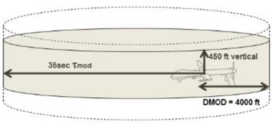
Figure 1.
RTCA DO-365 Well Clear volume definition [16].
The DO-365A WCV is defined independently from the onboard equipment of the intruder (i.e., cooperative if equipped with an ADS-B or Mode C transponder or non-cooperative if there are no traffic sensors onboard) and the altitude layer in which the encounter occurs. Guidance indications (i.e., the range of own RPA maneuvers that would result in an estimated Loss of Well Clear) are given to the Remote Pilot to support his decisions in the resolution of potential conflict.
Several DAA development projects have also been funded in Europe and some are still in progress. The MIDCAS project [13] developed a demonstration prototype of a complete Detect and Avoid system for all the airspace classes, including a RWC function. The RWC algorithm proposed in MIDCAS uses a spatial definition of the WCV to which is added a safety margin depending on the position measurement accuracy of the intruder and RPAS. It is independent from the intruder equipment and the altitude layer in which the encounter occurs. The MIDCAS RWC generates only one alert level proposing to the Remote Pilot a specific separation maneuver to execute.
Another RWC solution is that proposed by the SESAR PJ13 project [12], still in progress. It aims to enable IFR RPAS operations in controlled airspace classes A-C through the development of a full DAA system. To the best of the authors’ knowledge, the PJ13 WCV is defined through a spatial threshold on the vertical plane and a spatial and temporal threshold on the horizontal plane. Its dimension changes depending on whether the intruder is ACAS equipped or not. It has only one level of RWC alert, without supporting the Remote Pilot with guidance indications as he/she must always contact the ATCo to receive instructions, being in a controlled airspace.
The European DAA System program (EUDAAS) [14] under the European Defence Industrial Development Program (EDIDP) framework just started on 1 December 2020. It aims to develop a full DAA system for all the airspace classes. Here, the WCV is defined through a spatial threshold for non-ACAS equipped intruders. In case of ACAS equipped intruders, the RWC uses the same volume definition of TCAS-II that is also characterized by the horizontal temporal threshold. In this last case, all the WCV thresholds depend on the altitude layer at which the conflict occurs. Two are the RWC alert levels used, the Advisory Alert, indicating to the RP that an intruder meets a pre-defined condition, that may graduate to a Caution Alert that indicates a predicted Loss of Well Clear condition in the future. Even in this case, the RP is supported by the guidance indication in the resolution of a potential conflict.
Finally, in 2019 the EUROCAE issued the OSED document [11] providing a basis for assessing and establishing operational, safety, performance, and interoperability requirements for the DAA RWC and CA functions in classes D–G airspaces. In this document, no specific indications on the WCV definition are given, but assumptions and operational requirements for the definition of the RWC alerting and guidance functionalities are stated.
In this scenario, the present work uses the ED-258 [11] as the steering document for the definition of the RWC alerting and guidance requirements and integrates it with further applicable requirements from the RTCA DO-365A [16], considering the European airspace peculiarities as previously described. The WCV definition is made starting from that given in the RTCA DO-365A, but by modifying the threshold values through the analysis of fast-time simulation results made by exploiting the European Encounter model (i.e., a set of significative encounters in the European airspace) CAFÉ [20]. As in the EUDAAS and the PJ 13 projects, the WCV thresholds are functions of the intruder equipment and are: cooperative with ACAS, cooperative without ACAS, and non-cooperative. This last class has been introduced as it is possible to have aircraft without any transponder onboard in the airspace classes D–G. Moreover, another element defining the WCV thresholds of the proposed solution is the altitude; in the European airspace an aircraft flying below 10,000 ft has a speed limitation of 250 kts. Finally, the RWC function has two alerting levels as specified in the ED-258. It supports the Remote Pilot with guidance bands defined following the DO-365 proposed algorithm. All these aspects and peculiarities of the RWC solution will be analyzed in detail in the next sections.
3. Requirements of the Remain Well Clear System
The process followed for the definition of the RWC requirements started with the identification of the applicable requirements at the European level in the ED-258 [11]. Further, the US requirements described in the RTCA DO-365 [15,16] have been analyzed. The result comprised:
- Requirements directly usable;
- Requirements usable but with a change in the quantification;
- Differences in underlying assumptions having implications on function and/or quantification;
- Gaps with respect to the ED-258 applicable requirements and URClearED objectives.
Based on this analysis, new requirements have been defined to mitigate the gaps and to harmonize the overall results with the outcome of past and current European projects such as SESAR PJ13 [12], MIDCAS [11], and EUDAAS [14].
Through the previous process, the requirements describing the following fundamental aspects of the RWC system have been defined:
- The definition and quantification of the volume of airspace around the own RPA that needs to be protected (the RWC volume). This may depend on the performance of both the own RPA and the intruder.
- The alerts that have to be provided in case it is predicted that the RWC volume will be violated.
- The guidance that has to be provided to support the pilot in making a maneuvering decision that is intended to avoid the LoWC.
- The interoperability with the separation management layer handled by the ATCo (i.e., avoid time overlapping between RWC alerts and the ATCo separation service).
- The minimization of resolution advisory (RA) activation in encounters with ACAS equipped aircraft before, during, and after an RWC maneuver.
- Ensuring compatibility of the RWC guidance in case an RA is issued by the intruder.
- The need to deal with both cooperative and non-cooperative traffic.
In the next sections, all these points will be analyzed in order to completely define the RWC algorithm.
4. RWC Concept for Airspaces D to G
In this section, the operational scope of the proposed RWC algorithm is specified in the context of the overall ATM environment. The focus is on air traffic conflict management, defined by ICAO as the process used for limiting the risk of collision between aircraft and hazards to an acceptable level. Conflict management is normally addressed at three different operational layers, defined as strategic (planning), tactical (separation), and emergency (collision avoidance) layers.
The proposed solution is focused exclusively on the tactical level, namely in airspace classes D to G, where the responsibility not to operate in hazardous proximity belongs to either the ATCo or the pilots, depending on the airspace classes and type of flight rules (IFR or VFR). The goal of the above actors at a tactical layer is to keep traffic safely separated from each other and to minimize the risk of a near mid-air collision (NMAC, i.e., a situation in which two aircraft simultaneously come within 100 ft vertically and 500 ft horizontally of each other).
In this context, the RWC function supports the remote pilot in her/his responsibilities with regards to the rule of the air: “An aircraft shall not be operated in such proximity to other aircraft as to create a collision hazard”, as stated in [4].
4.1. Operational Concept
Several elements characterize the operational context in which the proposed solution shall operate, as depicted in Figure 2.
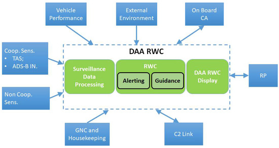
Figure 2.
RWC operational context.
The DAA RWC system includes the RWC Alerting and Guidance functions, the Surveillance Data Processing function and the DAA RWC Human–Machine Interfaces (HMI). The DAA RWC system interfaces with a number of other systems and requires several other types of operational information, described below:
- A suite of both cooperative and non-cooperative sensors. These sensors supply air traffic measurements in terms of intruders’ position and velocity, with their respective accuracies, and information about the intruders’ status. Specifically, a Mode-S transponder, coupled with an active surveillance transponder (TAS), constitutes the cooperative sensor suite, while the radar constitutes the non-cooperative sensor. Non-cooperative sensors are required explicitly in airspace classes D–G because, other than in classes A to C, it is possible to encounter intruders not equipped with transponders.
- The Guidance, Navigation, and Control (GNC) system that provides the overall state information of the own RPA.
- The Collision Avoidance (CA) function that sends to the RWC function direct information regarding the activation of any associated traffic or resolution advisory. This information is needed by the RWC system to avoid visualizing misleading or contradictory indications with respect to the CA system.
- The Command and Control link (C2L), through which the DAA RWC system interchanges relevant data between the RPAS airborne and ground segment, e.g., intruder traffic tracks, alerts, status data, commands, etc.
For increasing the Remote Pilot’s situational awareness and to improve the selection of appropriate RWC guidance maneuvers, the RWC function may incorporate further information about fixed obstacles, severe weather, terrain, and no-fly zones.
In our case, we suppose that the RWC function does not process such information. Instead, it is the RP that in the negotiation/decision of the RWC maneuver to execute is always aware of the prevailing weather and visibility conditions in which the RPA is flying and also of the environmental constraints, through a multifunctional display.
4.1.1. Surveillance Data Processing Function
Given the above operational context, the Surveillance Data Processing collects measurements from each cooperative and non-cooperative traffic sensor (local processing) and then performs a data correlation to generate an accurate single set of consolidated and formatted track data (global processing).
Local data processing is specific to each kind of supported sensor. The functions performed by the local data processing are essential to initiate new intruders’ tracks and to assess, complete (if needed), and validate each received traffic report.
The global data processing uses the consolidated local data reports from each available sensor to output a single consolidated set of traffic reports. The key objective of this functionality is to select valid tracks and then to correlate, filter, and validate traffic reports for building up a single set of consolidated tracks.
The consolidated set of traffic reports is then time synchronized with respect to the RPA current time (i.e., the coordinated universal time provided by the Global Positioning System receiver onboard the RPA). A traffic database is used for estimating the parameters of a numerical model that predicts future positions along the current track. If needed, these data are also used to estimate the current position and velocity of a missing (due to temporary lack of sensor data) traffic track up to a predefined time interval.
All of the above functions related to Surveillance Data Processing are common to both RWC and CA functions.
4.1.2. RWC Functions: Alerting and Guidance
The key objective of the RWC function is to support the RPAS pilot in avoiding the violation of the Well Clear volume. This support is achieved by providing the pilot with both alerting and guidance functionalities.
The alerting functionality aims to determine whether an intruder poses enough risk to warrant an alert and, if so, which alert priority is appropriate. Specifically, the RWC alerting function propagates the RPA and intruder’s measured state, using the projection parameters computed by the Surveillance Data Processing system, in order to evaluate the issuing of the following alerts (Figure 3 [11]):
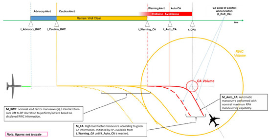
Figure 3.
Overall timeline, RWC, and CA concepts [11].
- The advisory alert, indicating when a change in current heading/track or altitude by the own RPA may immediately trigger a caution alert. The RP response to an advisory level alert is to monitor the designated traffic by assessing the overall situation of the encounter and to be aware of the risk of inducing a Loss of Well Clear situation, due to possible future maneuvers or mission constraints. Contacting ATCo in response to an advisory alert should be avoided.
- The caution alert, indicating a predicted or current Loss of Well Clear situation. This alert aims to get the attention of the RP for determining whether a Remain or Regain Well Clear maneuver is needed and to initiate coordination with ATCo if required. The alert necessitates immediate awareness of the RP and subsequent actions.
As described in § 3, the RWC system tries to avoid an overlap between the RWC Caution alert and the separation minima used by the ATCo for detecting a potential Loss of Well Clear. In a similar way, when dedicated systems, such as the Short-Term Conflict Alert [21] system, are used by ATCo to provide the separation service in controlled airspace, negative interactions should be avoided. The proposed RWC concept is designed to alert the RP only after nominal time/space thresholds for detecting a potential loss of separation by the ATCo are far exceeded. In this way, a negative interaction between existing separation management systems and DAA that could lead to additional communication and workload for both ATCo and RPs is avoided.
The guidance functionality computes indications to support the decision making of the RP concerning the resolution of a potential conflict. For each consolidated traffic track recognized as a threat by the RWC alerting functionality, the guidance function computes the conflict bands that indicate the range of own RPA maneuvers for track/heading angle and altitude predicted to cause a Loss of Well Clear. Such guidance indications are generated considering the RPA nominal performance.
Moreover, it shall be noted that there may be situations in which the aircraft is already inside the Well Clear volume (WCV) or where there is no maneuver that would avoid LoWC but no Collision Avoidance alert has been issued. This can happen when the RWC maneuver was delayed for too long or when a Collision Avoidance maneuver has been performed but Well Clear conditions have not yet been re-established. In these cases, the RWC function computes the Regain Well Clear guidance, which is conceptually the same as the Remain Well Clear guidance, with the only difference that it is provided after the Loss of Well Clear condition.
The propagation ahead in time used for the issuing of the Caution alert and for the computation of guidance indications will consider the time needed by the RP to both:
- Assess the overall situation of the encounter by assessing whether the intruder is flying under IFR or VFR, whether the intruder has the right of way, whether it is ACAS equipped or not, etc.
- Coordinate changes in the assigned clearance with the ATCo and execute the Remain Well Clear maneuver considering any associated communication delay, if needed.
Note that the RWC function computes the conflict bands without considering the environmental constraints in terms of fixed obstacles, terrain, no-fly zones, and weather conditions. As such, the RPAS pilot remains responsible for integrating the RWC indications with any other available system to obtain and maintain adequate situational awareness.
Moreover, since the RWC function is not able to reliably know whether an aircraft is a priority intruder (e.g., gliders, balloons that are not normally equipped with transponders), no right of way maneuver indications are provided on the DAA RWC Display in order to avoid misleading indications in such special cases.
Even though the proposed RWC function extends to airspace classes D to G and a wide variety of intruders, the proposed concept of operation remains equivalent. The RP shall react accordingly, being responsible for keeping full awareness of the airspace class in which the RPA is flying and whether the intruder is operated IFR or VFR. The RWC function will need to distinguish between:
- ACAS equipped or unequipped aircraft, using different thresholds as the function of the operating altitude (i.e., as done by the TCAS-II algorithm).
- Cooperative and non-cooperative traffic (i.e., transponder-equipped or not-equipped aircraft).
- The altitude levels.
4.1.3. RWC Display Function
In order to improve the RP situational awareness, the DAA RWC Display function shows traffic information, alerts, and guidance indications on a specific graphical display of the RPS HMI, called Cockpit Display of Traffic Information (CDTI). It consists of two main views:
- A horizontal view of the surrounding traffic in which each aircraft is displayed by a symbol that depends on the associated active alert using a unique color code to show alerts.
- The horizontal and the vertical conflict bands as computed by the guidance function.
The state of the RWC function is displayed to the RP with an option to activate/deactivate the DAA functionalities as needed. In case of a C2L loss, the DAA RWC Display activates an explicit message of link loss.
4.2. DAA RWC Functional Architecture
The ED-258 functional architecture has been tailored to the URClearED scope, yielding the detailed functional architecture as in Figure 4.
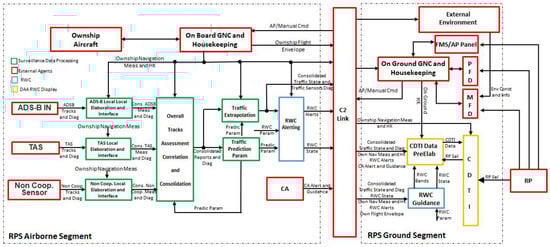
Figure 4.
RWC detailed functional architecture.
The defined architecture is characterized by an airborne and a ground segment, where the Surveillance Data Processing, the RWC, and the DAA RWC Display functions, interacting with external agents, are allocated.
The Surveillance Data Processing receives input from the traffic sensors’ measurements and accuracies that are first locally assessed and then globally correlated in order to generate a single consolidated report for each intruder detected. The consolidated report set is stored in a database that is used to compute the prediction parameters. These parameters are used first by the Traffic Extrapolation module that synchronizes the intruder reports to the current time of own RPA and then by the RWC Alerting function to determine possible Loss of Well Clear conditions ahead in time. All this information, together with the own RPA navigation measures, is sent to the ground segment and input to the RWC Guidance module for the conflict bands computation and the CDTI Data Pre-Elaboration module that interfaces with the CDTI.
In order to complete the overview of the functional architecture, a brief description of the external agents is given below:
- ADS-B IN: implements the ADS-B IN sensor outputting the detected surrounding traffic in the extended squitter message format.
- TAS: implements the active traffic sensor outputting the detected surrounding traffic in a proper format. Such a sensor allows the RPAS to know whether an intruder is ACAS equipped or not, supporting the interoperability in case of resolution advisories (RAs).
- Non-Cooperative Sensor: implements a generic non-cooperative sensor capable of replicating the performance of a radar and/or EO/IR sensor.
- Onboard GNC and Housekeeping: represents the guidance, navigation, and control functionalities of the RPA. It inputs to the DAA RWC system a consolidated state of the own RPA aircraft (position, velocity, attitude, and time of applicability) and measurement accuracies, together with the housekeeping variables related to the own RPA sensors, actuators, and wind information. It also executes the maneuvers selected/made on-ground by the RP. The aircraft flight performance values, eventually updated online, are output.
- CA: The collision avoidance functionality of the RPAS that interacts with the CDTI and the onboard GNC in order to visualize the collision avoidance alerting and guidance indications and to execute automatic collision avoidance maneuvers, respectively. This functionality is out of scope with respect to the present work.
- C2 Link: A link for the exchange of data between the airborne and the ground RPS segments. It introduces a variable delay in the communication due to the radio line-of-sight or the beyond radio-line-of-sight conditions. A temporary or complete loss of communication can occur.
- On-Ground GNC and Housekeeping: Implements the on-ground flight management system (FMS) and AP panel logics through which the RP commands the RPA to execute a maneuver (e.g., an RWC maneuver) or a specific flight plan. It also manages the housekeeping of the on-ground systems, detecting, for example, the state of the C2L (i.e., working/not working).
- External Environment: Assesses the environment in which the own RPA is flying, namely: the weather hazards, the terrain, the surrounding no-fly zones, and obstacles. Such information is displayed on the on-ground HMI in order to further increase the RP situational awareness.
- PFD: The primary flight display located in the RPS shows to the RP information about the own RPA current altitude, vertical speed, IAS, attitude, etc. It helps the RP to evaluate the current own RPA state and flight condition.
- MFD: The multifunctional display located in the RPS gives to the RP information about the weather conditions, terrain, fixed obstacles, NavAids, no-fly zones, and aeronautical charts in the area of interest. It helps to increase the RP’s situational awareness.
- FMS/AP Panel: The RP can interact with the onboard FMS and AP through the related panels located in the RPS. Such panels allow the RP to execute maneuvers in an automatic mode, add/remove/modify waypoints to the current flight plan, or add/remove/modify flight plans.
- RP: The RP directly interacts with:
- ○
- The CDTI in order to change the display view (e.g., horizontal range of visualization) or to activate/deactivate DAA RWC functionalities.
- ○
- The PFD and MFD to increase his/her situational awareness with respect to surrounding obstacles, weather conditions, and terrain, if such information is not fully or partially displayed on the CDTI.
- ○
- The FMS/AP Panel to execute RWC maneuvers.
- ○
- Inceptors to manually execute a maneuver.
The definition of the functional architecture has been made, considering the following assumptions:
- The Surveillance Data Processing functionality is deployed on the RPAS airborne segment supporting the CA functionality and avoiding communication issues (i.e., delay in sending sensor measures to onboard through the C2L).
- The Surveillance Data Processing, uses a track-to-track fusing algorithm characterized by a hierarchical structure:
- ○
- A sensor-level tracking.
- ○
- A track-level fusion for the multiple sensor system in order to generate central tracks (i.e., single consolidated track report for each detected intruder).
- The sensor-level tracking algorithm that processes the sensor measurements to estimate the intruder’s position and velocity with related accuracy is integrated into the traffic sensor model as it is outside the scope of this paper.
- The Traffic Extrapolation module performs only linear trajectory extrapolation.
- The RWC Guidance function is hosted in the RPAS ground segment. The underlying rationale is that no RWC automatic maneuver is foreseen. For future integration with on-ground systems (e.g., geofencing, geocaging, weather stations, aeronautical database, etc.) this choice avoids additional communications and computational issues.
- The RWC Alerting function is hosted on the RPS airborne segment. This supports (future) integration with the collision avoidance functionality (e.g., filtering the most dangerous threat) and integration with the FMS (e.g., taking advantage of the own RPA intent information for the RWC alert issuing).
4.3. Surveillance Data Processing
Figure 5 shows the internal architecture of the Surveillance Data Processing function starting from what has been depicted in Figure 4.
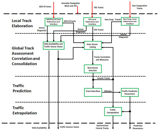
Figure 5.
Surveillance Data Processing detailed architecture.
The traffic sensor trackers, integrated inside the sensor models (see implementation assumptions in the previous section), provide the detected intruder’s state in terms of position, velocity, and related accuracies to the local track elaboration modules. These modules:
- Evaluate the track accuracies in order to discard non-significant information. The thresholds with respect to evaluate the described conditions are parameters of the modules.
- Check report completeness and tag the tracks that are without altitude or bearing information.
- Manage a local database in which the tracks that are older than the current time of own RPA are discarded. The stored ADS-B, non-cooperative, and TAS tracks are terminated after 10 s, 4 s, and 10 s, respectively, as indicated in DO-365A.
- Output the intruder’s information in a standard data format in order to make all the other modules of the DAA system independent from the traffic sensor devices onboard. This means that a change of a traffic sensor device requires only a modification of the related surveillance local elaboration module.
- Output the diagnostic of the related traffic sensor in terms of its availability onboard (i.e., in the implementation the possibility has been foreseen that the RPAS can suffer from reduced equipment performance) and current state (i.e., sensor properly working or in failure).
The diagnostic outputs of the previous modules serve as input to the DAA Availability and Traffic Sensor Status module that evaluates the RWC availability. If the own RPA is in an airborne state above 500 ft, the RWC function is available, otherwise all its functionalities are inhibited; neither alert nor guidance indications are generated.
In order to link sensor tracks for the same intruder from multiple sources (i.e., ADS-B IN, active traffic sensor, and non-cooperative sensor) to a single central track belonging to the intruder, the Inter-Sensor Linking module has been developed. The algorithm of this module follows the DO-365A, where the linking is based on the nearest neighbor paradigm [16].
Using the position of the sensor track and the extrapolated position of the central track in the north-east-up reference frame and in spherical coordinates at the own RPA, the following parameters are calculated for track linking:
- North, east, and vertical position difference.
- Lateral position difference.
- Range, bearing, and elevation difference.
If the ICAO address in the sensor track and in the central track match, then the sensor track is linked to the central track and the link parameters are updated to this link. Otherwise, the previous computed linking parameters are used to find a new link or to generate a new central track as detailed in the flow charts reported in DO-365A for each type of sensor [16].
Once linked, the global tracker performs a preferred or Best Sensor Selection for the estimated horizontal position and velocity based on the sensor track’s propagated horizontal position uncertainty at the time of linking. The same is done for the vertical position and velocity based on the vertical rate uncertainty. The preferred sensor is maintained separately for the horizontal and vertical estimates.
To avoid toggling of the preferred sensor, it is switched only if the alternate sensor track has better uncertainty for at least 2.5 s (tunable parameter). The uncertainty refers to the propagated positional uncertainty for the horizontal estimates and the vertical rate uncertainty for the vertical estimates. For the preferred sensor for the vertical estimates, cooperative sensors are prioritized over non-cooperative sensors, and this sensor prioritization precedes the vertical rate uncertainty. To avoid extended periods without track updates, the preferred sensor is switched if no track updates have been received by the preferred sensor for at least 5.5 s (tunable parameter). This is done to avoid stale track estimates being used during extrapolation at each one-second epoch. The algorithm follows the flow chart shown in DO-365A [16].
The Best Sensor Selection module tags the central tracks in case these are unvalidated ADS-B tracks or an intruder without bearing and/or altitude. In case of an ACAS equipped intruder, a specific field of the central track data structure is filled, indicating whether an RA has been issued and which kind of resolution maneuver has been agreed.
For each central track, up to eleven samples are stored in a database.
The Traffic Prediction Parameters module estimates the values of the parameters that are used to make a projection of the traffic state. The data from the track database is used to evaluate the following target parameters:
- Track horizontal velocity; evaluated as the last available intruder horizontal velocity.
- Track chi last; evaluated as the average of the available target track angle (maximum five track angle values) if the absolute value of the estimated turn rate parameter is lower than a turn rate threshold, otherwise it is evaluated as the last available target track angle.
- Track vertical velocity; evaluated using a simple linear regression method.
Finally, the Traffic Extrapolation module synchronizes the state of each intruder to the current own RPA time of week using the prediction parameters previously computed. The synchronization is made through a straight projection of the trajectories.
4.4. RWC
After a brief description of the quantification of the RWC volume, a detailed description of the alerting and guidance functionalities is given.
4.4.1. Quantification of RWC Volume
For an RWC function to work properly, it is needed to unambiguously define and quantify the Well Clear volume around each intruder that shall be not violated to avoid Loss of Well Clear. Several studies have been promoted in order to quantify such volume. However, there is no standard quantification that is generally accepted by the aeronautical community. For the US, the RTCA MOPS DO-365 quantifies a WCV based on several analysis and test campaigns, while a somewhat different quantification is currently adopted in Europe within SESAR PJ13-Sol. 111 (for airspace classes A to C), as derived from the MIDCAS project. Nevertheless, a common definition of the WCV is possible that can encompass any specific quantification that are currently proposed. Such definition is based on the below described parameters.
- A safety performance requirement is associated with the WCV, e.g., the maximum probability of an NMAC after an unmitigated excursion into WCV, or similar.
- The WCV uses a Horizontal Spatial Threshold (HST) to guarantee a minimum horizontal separation in any direction.
- The WCV can use a Horizontal Temporal Threshold (HTT) to yield a guaranteed minimum time between Loss of Well Clear and potential breach of the NMAC boundary.
- The WCV uses a Vertical Spatial Threshold (VST) to guarantee a minimum vertical separation.
The resulting shape of the WCV based on the above definition is basically a cylinder around the intruder with the circular base in the horizontal plane (see Figure 6) that is enlarged in some direction in case a horizontal temporal threshold is also used.
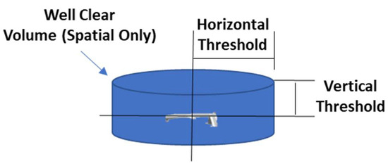
Figure 6.
Shape of the spatial only Well Clear volume.
In the URClearED project, the quantification of the above mentioned WCV thresholds has been performed by means of a proprietary dynamic simulation tool that is able to simulate a pair-wise encounter starting from given initial conditions. For the different investigated Well Clear quantifications, the tool predicts LoWC within a given time interval, called Look Ahead Time (LAT). The tool also computes horizontal and vertical conflict bands, evaluating the situation in the LAT until no maneuver is possible in both these planes. No maneuver is executed, however, so this tool is only able to perform “Open Loop” simulations.
The analysis has started from the current definitions that can be applicable to the topic analyzed in the present paper, verifying which is more applicable to the operational scenarios defined for the URClearED RWC concept.
Considering that RWC shall be installed in different classes of vehicles and shall be used in encounters with intruders of different types and equipment, but only some of the information is available from the surveillance sensors, the methodology has been to select a WCV that can be different depending on the host vehicle, class, intruder class, equipment, and altitude (because of the velocity limitation below 10,000 ft). Thus, the following high-level steps have been performed:
- Selection of one of the possible WCV quantifications from available standards and projects that have already performed some analysis.
- Definition of the performance of the host vehicle. These performances are chosen among two classes of vehicles: one with relatively low maneuverability and a second one with higher maneuverability. The performance of these two vehicles’ classes is reported in Table 1.
 Table 1. RPAS performance range used for the WCV quantification.
- 3.
- Selection of the encounter altitude. Altitude has little effect on an encounter, given the assumptions we used in the tool. Therefore, it is only considered that a difference is established between the range of altitudes below 10,000 ft (where there is a limitation of speed up to 250 knt) and above 10,000 ft (where no speed limitation applies).
- 4.
- Selection of the type and velocity of the intruder.
- 5.
- Execution of the Monte Carlo analysis in which generic encounters are uniformly generated using the following intervals of values:
- ○
- Horizontal Miss Distance [0 … 500] ft, any angle;
- ○
- Vertical Miss Distance [−100 … 100] ft;
- ○
- RPAS speed [50 … 100] knts (TUAV/RUAV) and [70 … 200] knts for MALE;
- ○
- Direct Angle [−110 … 0] Non-Coop. intruders, [−180 … 0] Coop. intruders;
- ○
- RPAS Flight Path [−3 … +3] deg;
- ○
- Intruder Flight Path [−3 … +3] deg.
- 6.
- Evaluation of the results through the following criteria:
- ○
- Time difference between the Caution alert time and the RWC last possible maneuver greater than the latency of the RP/ATCo interaction and C2L;
- ○
- Time difference between the RWC last maneuver and resolution advisory alert greater than zero;
- ○
- Range of Caution alert below the surveillance sensor ranges;
- ○
- Time at Caution alert below the ATCo acceptable time for cooperative intruders in order to avoid overlapping between RWC and ATCo;
- ○
- Range of Caution alert below the visual range of non-cooperative intruders in order to allow an intruder that has only Visual Based Separation to see own RPA.
Based on the above analysis results and related discussions, a final set of the WCV quantification and alerting times have been selected for evaluation by pilots and controllers during the real-time simulation (RTS) campaign. Table 2 reports the TUAV/RUAV and the MALE WCV quantification and alerting time.
Table 2.
TUAV/RUAV and MALE WCV quantification and alerting time.
4.4.2. RWC Alerting Function
Figure 7 shows the RWC Alerting function, detailing its internal architecture with respect to what has been depicted in Figure 4.
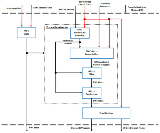
Figure 7.
RWC Alerting module detailed architecture.
The DAA availability, together with the traffic sensor status in output from the Surveillance Data Processing module, are input to the RWC State module that evaluates whether:
- The RWC function is working properly;
- There is an RWC function degradation due to a degradation of the own RPA onboard navigation measures or to a failure of one of the traffic sensors onboard;
- There is a loss of the RWC functionality due to a critical alarm such as: own RPA GPS loss or no traffic sensors properly working.
This information is both an output from the RWC Alerting module and is used internally, together with the airborne/on-ground state of a detected intruder to enable the alerts’ computations.
For each intruder, the RWC Parameters Selection module outputs the parameters needed to define the WCV depending on the intruder type and altitude as reported in the previous section. Together with the prediction parameters, the synchronized relative position and velocity of the intruder are used by the RWC Alerts Computation module to issue advisory or caution alerts.
Such alerts are generated when the intruder and the own RPA straight trajectory projection on the look-ahead time satisfies the following condition [15]:
where is the predicted modified tau, HMDp is the predicted Horizontal Miss Distance at closest point of approach, and dh_p is the predicted vertical separation.
The computed alerts and conflict indicators (e.g., time to closest point of approach, horizontal closure rate, vertical closure rate, etc.) serve as inputs to the Alerts Filter module that inhibits a caution alert in case the time to closest point of approach is above a threshold specified by the RWC Parameters Selection module. Finally, in order to avoid unstable alerts on the display, the Alerts Persistence module holds the Caution alert for a specified time.
The Prioritization module sorts the central tracks through the associated alert level in the following order: Collision Warning or RA (from CA/ACAS), RWC Caution Alert, RWC Advisory Alert, distance/altitude difference. In case different tracks have the same RWC alert level, the time left to entering the WCV (in ascending order) is considered.
4.4.3. RWC Guidance Function
Figure 8 shows the RWC Guidance function, detailing its internal architecture with respect to what has been depicted in Figure 4.
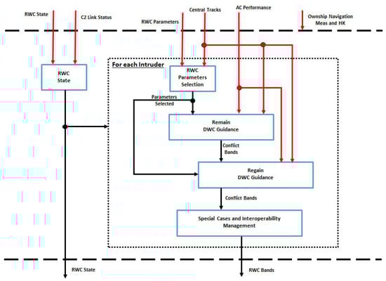
Figure 8.
RWC guidance module detailed architecture.
This module is hosted in the RPS ground segment. It receives data from the onboard segment through the C2L.
The RWC State module updates the received onboard RWC state through the evaluation of the C2L status, if the C2L loss condition is above a time threshold, the RWC system status is switched to a failure condition to avoid the stale tracks estimation.
This information is both an output from the RWC Guidance module and is used internally, together with the airborne/on-ground state of a received intruder.
For each intruder, the RWC Parameters Selection module outputs the parameters needed to define the WCV depending on the intruder type and the altitude as specified in §4.4.1. That information serves as input to the Remain DWC Guidance module. For the generation of the conflict bands in the horizontal plane, the implementation follows the NASA DAIDALUS algorithm [22]. For the vertical plane, the generation of the conflicting altitudes that are predicted to result in a Loss of Well Clear within the look-ahead time, the implementation uses a customized algorithm.
For the computation of conflicting ranges of track, the own RPA maneuver is performed by simulating the maximum allowed acceleration on the horizontal up to a predetermined track value and then going straight up to the look-ahead time, while keeping constant velocity on the vertical axis and evaluating the Loss of Well Clear conditions (Figure 9).
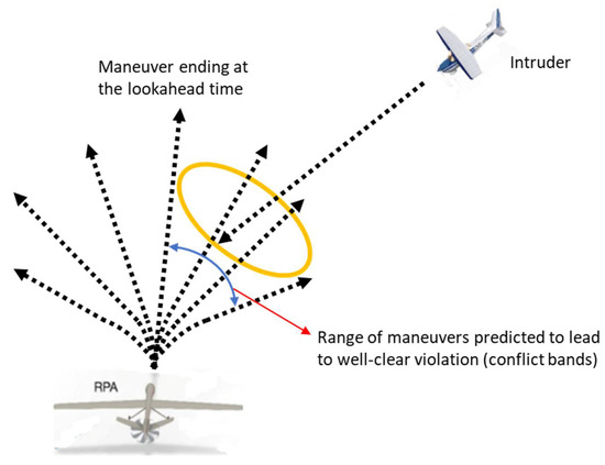
Figure 9.
Aircraft state projection for the computation of the horizontal conflict bands.
For the calculation of conflicting altitudes, an adjustable vertical speed is used to reach a predefined altitude that is held up to the look-ahead time, while keeping constant velocity on the horizontal plane and evaluating the Loss of Well Clear conditions (Figure 10). The intruder trajectory projection is always considered straight.
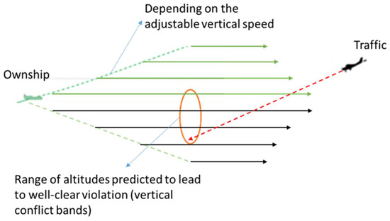
Figure 10.
Aircraft state projection for the computation of the vertical conflict bands.
In case the conflict bands saturate or the aircraft is already inside the Well Clear Volume, the RWC Guidance module computes the Regain Well Clear guidance. They are conceptually the same as the Remain Well Clear guidance, with the difference that the conflict bands are provided after the Loss of Well Clear removes the horizontal temporal condition (i.e., only a spatial WCV is also used on the horizontal plane).
Once the conflict bands have been computed they are modified by the Special Cases and Interoperability Management module. This considers the effects on the conflict bands of intruders without altitude or bearing and on ACAS equipped aircraft that have issued an RA.
The following rules are used:
- In case an intruder without bearing has been detected, the horizontal bands are saturated.
- In case an intruder without altitude has been detected, the vertical bands are saturated.
- In case an intruder issues a vertical RA, the vertical bands are saturated depending on the type of resolution maneuver (i.e., climb or descend).
- In case an intruder issues a horizontal RA, the horizontal bands are saturated depending on the type of resolution maneuver (i.e., left or right turn).
4.5. DAA RWC Display
The DAA RWC Display functionality is split in a pre-elaboration module (CDTI Data Pre-Elaboration) and in the CDTI itself.
The CDTI Data Pre-Elaboration is the only module that interfaces with the CDTI. It manages the data format of the information to send to the display, namely: the traffic state, the DAA alerting and guidance bands, the DAA overall state (i.e., full operative, degraded mode, not working), and the traffic sensors’ status. Moreover, it acquires and processes the selections made by the RP through the CDTI and, specifically, the manual deactivation of the RWC functionalities.
The CDTI layout is shown in Figure 11. The Human–Machine Interface (HMI) is based on a standard navigational display as detailed in RTCA DO-257B [23]. Further, basic requirements have been extracted from RTCA DO-365A [16], keeping only those that were considered applicable to the URClearED project. It is composed of a horizontal display showing the own RPA in relation to its surrounding traffic and a vertical view of the conflict bands. The heading of the own RPA can be seen on the surrounding compass rose. If no own RPA heading is known, the tic marks and labels on the compass rose will disappear. In that case, traffic will still be displayed relatively to the own RPA if such information is available.
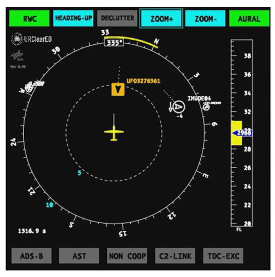
Figure 11.
View of the CDTI displaying the surrounding traffic together with the alerting conditions, the horizontal and vertical conflict bands, and the overall status of the DAA RWC system.
The horizontal display provides indications of intruder positions in a top-down view relative to the own RPA’s position, that is, with the own RPA in the center. Depending on the pilot’s choice, traffic is represented in a heading-up, track-up, or north-up orientation. If available, the current direction (that is, the heading) of the traffic will be shown. In that case, traffic is represented as a directional symbol (arrowhead), otherwise a non-directional symbol (diamond) is used. This depends on the information that is received from sensors and traffic information sources. Traffic outside the chosen maximal range of the CDTI are placed on the edge of the compass rose with reduced symbol size. Symbol colors will represent the individual traffic state:
- White represents usual non-threat traffic.
- Cyan represents traffic for which an advisory alert has been issued.
- Amber represents traffic for which a caution alert has been issued.
It should be noted that the color red is not used and is reserved for higher alert levels and CA applications. Whenever a traffic symbol becomes amber, there is a caution alert. An aural annunciation will be heard saying: “Traffic! Avoid!” This aural alert can also be deactivated by the RP. Traffic symbols are kept on the CDTI as long as updates are being received under the particular identifier from the CDTI Data Pre-Elaboration module. In absence of updates, the symbols are frozen and then, after a specified time, faded out.
Conflict bands located on the outer edge of the compass rose indicate hazardous directions. This information is generated by the RWC component and can be used to indicate alert levels in the respective direction. Conflict bands are shown in the same orientation as the entire display, that is, heading-up, track-up, or north-up. The color of the conflict bands is always yellow, independent of the associated traffic alert state. That means that, for example, an Advisory alert intruder with a cyan symbol generates a yellow band, as well as a Caution alert intruder with an amber symbol. For this reason, the color yellow has been chosen deliberately to be different from amber.
Each traffic symbol generates a trace of “breadcrumbs” in relative coordinates on the CDTI. The effect of this is that a trace of breadcrumbs pointing directly towards the own RPA indicates a collision course, assuming that both aircraft maintain their current course. This allows the RP to more easily identify hazardous courses.
Information about the current state of the traffic sensors and the RWC function are shown to the RP using colored buttons. The top row of buttons can be manipulated to switch off the RWC function, to change heading mode, to declutter the display, to change the zoom level, and to switch off aural alerts. The bottom row cannot be manipulated and merely shows the state of ADS-B, TAS, non-cooperative sensors, C2L, and whether the maximum number of displayable traffic (in this case 30) has been exceeded, i.e., whether there is possibly invisible traffic.
The RP can acquire additional information about traffic by selecting an intruder, e.g., by clicking on the symbol. This information may include, e.g., altitude and speed, if these are available. The additional information is represented by a “data block”, see Figure 12.
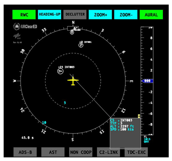
Figure 12.
Data block shown for a selected intruder.
The CDTI can be switched into a decluttered mode. In this case, callsigns, breadcrumbs, timing display, and the data block display will be removed to get a cleaner view of the situation, see Figure 13. Switching into cluttered mode returns these elements.
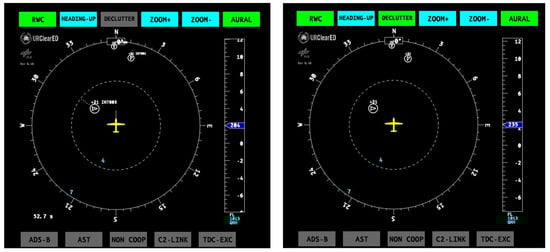
Figure 13.
Display in cluttered and decluttered mode.
Finally, the bottom-right corner shows a timing display. In the RTS tests, this was used to show a time reference relative to the currently running experiment. However, in practice it can be used to display additional conflict information, e.g., time to CPA.
4.6. Differences between the US and the European RWC
The main differences between the US and the European URClearED RWC are:
- Quantification of the Well Clear volume has been revised and is based on fast-time simulations and the EUROCONTROL CAFÉ encounter model [20];
- Removal of the DO-365 warning alerts [15], because in the European context the RP flying in classes D and E is not allowed to perform maneuvers without clearance from ATCo;
- Advisory alert is defined differently from the DO-365 preventive alert;
- Caution alert times are based on FTS and the EUROCONTROL CAFÉ encounter model;
- Different behavior of the system in encounter with ACAS equipped intruders;
- Different behavior of the system in encounter with non-cooperative intruders;
- Simplification and reduction of information to essential ones for the HMI;
- Definition of RP operational procedures compliant with current European rules.
5. Real-Time Test Campaign
The validation of the RWC functionality, interoperability, and human requirements is a complex task that has been approached through a validation campaign divided into multiple phases involving fast-time and real-time simulations: fast-time simulations to prove compliance of functional and interoperability requirements and statistically validate/tune the RWC volume definitions and alert timings; real-time simulations to operationally validate the complete RWC concept with a special focus on the Human–Machine Interfaces for the pilot and the interactions among the RP, the ATCo, and the intruder pilot. In fact, they share the responsibility to manage a potential Loss of WC conditions within realistic operating conditions in the European airspace classes D–G.
Overall, three RT simulation campaigns have been carried out, specifically:
- A first RT campaign with the emphasis on a special build of a fixed-wing drone;
- A second RT campaign in which the improvements identified during the first RT campaign have been tested;
- A third RT campaign with the aim to test several builds of rotorcraft drones using the parameters consolidated during the second RT campaign.
In the next sections, after the description of the objectives of the RT simulations and the simulation infrastructure used to perform the tests, the most relevant results obtained during the first and the second RT test campaign will be given.
5.1. Real-Time Simulation Objectives
RTSs are characterized by human in-the-loop, thus the metrics are almost exclusively human performance based.
However, the human performance of both the controller and the Remote Pilot have been complemented by data result analyses for evaluating some validation objectives that have been not included in the FTS, due to the limited scope of the project. These were concerned mainly to:
- Evaluate the capability of RWC to avoid LoWC in nominal conditions accounting for the surveillance sensor accuracies, the presence of other interfering traffic (even causing simultaneous predicted LoWC), and the maneuver performed by the RP. This is needed because the FTS executed only concerned “Open Loop” evaluations (i.e., without actually performing the maneuver for avoiding LoWC) in peer-to-peer encounters, without sensor errors.
- Evaluate the interoperability of RWC with ACAS-equipped intruders (i.e., verify that the time interval from the Caution alert activation up to the execution by the RP of the Well Clear maneuver did not trigger the RA activation of the TCAS-II system).
- Evaluate the interoperability of RWC with ATCo separation provisions (i.e., the Caution alert does not overlap temporally to the ATCo’s separation indications).
- Evaluate the capability of RWC to manage some key contingency situations in which one of the systems involved in the encounter has an operational degradation due to a failure. The FTS did not analyze any of these situations. However, a comprehensive analysis of system resilience/robustness to any contingency situation was not in the scope of the URClearED project. Therefore, only the following contingencies have been considered: loss of voice communication, loss of C2L, and failure of some navigation/surveillance RPAS equipment.
The human performance (HP) objectives have been defined following the SESAR HP Assessment Process developed within the project 16.06.05 in Wave 1 and project 19 in Wave 2, and they try to:
- Assess whether the introduction of the RWC function in transition scenarios between different classes of airspace will have an impact on Remote Pilot and ATCo roles and responsibilities. In fact, the rules under which the conflicting aircraft are operating change according to the specific airspace classes involved. This could impact the roles and responsibilities of involved actors. If an IFR RPAS flying in airspace classes D or E interacts with VFR flights, the separation might be managed by an ATCo. In airspaces F to G IFR, aircraft will not receive ATCo separation provision;
- Assess whether there are any new information requirements on the Remote Pilot and ATCo side, communication modalities and means, communication load (that can affect the workload of the controller), and team situational awareness because the communication between the controller and the Remote Pilot might be subject to changes with the introduction of the RWC function;
- Evaluate the DAA RWC HMI in order to identify any negative effects on the Remote Pilot’s performance.
5.2. Real-Time Simulation Infrastructure
The evaluation of the RT objectives for the RWC prototype integrated into a fixed wing RPA simulator has been performed in the Integrated Simulation Facility (ISF) [24].
The ISF is a real-time HW and human in-the-loop facility composed of several simulators (i.e., Manned/Unmanned aircraft, Controller Working Position, etc.), each with its own specific task. This facility is designed to perform real-time simulations of the civil airspaces in which all agents, including pilots, ground control station Remote Pilots, and air traffic controllers, interact among each other in order to perform verification and validation of advanced avionic prototypes and ATCo systems and procedures.
The architecture of the first two RTS trials is shown in Figure 14. Additionally, the roles and positions of human participants in the tests are shown. Specifically, two different Remote Pilots, six controllers, one manned pilot, three human factor experts, and about eight engineers were involved in the execution of the test runs.
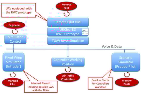
Figure 14.
Real-time simulation facility architecture.
The RPAS vehicle equipped with the RWC system was configured as a fixed-wing Tactical UAV and as a MALE with given minimum performances. Moreover, two Pseudo-Pilot stations were used to manage the traffic in the flight test areas and one Controller Working Position (CWP) station was used by controllers to perform ATCo tasks.
To online set and modify the testing scenarios as scheduled, the simulator/machines were connected to a dedicated Simulation Control station managed by test engineers. Finally, data were shared through a local area network and a voice link to emulate radio communications among pilots and controllers.
5.3. Real-Time Simulation Results
In this section, the results achieved during the two real-time simulation sessions performed with the fixed-wing RPAS in both the configurations, TUAV and MALE are analyzed.
A total of seventy-one encounters were analyzed (Table 3). The data show that the LoWC situations that occurred during the tests are due to:
Table 3.
Summary of the RT simulations results.
- Contingencies (e.g., the RWC system did not work or the RP had difficulties in the execution of the RWC maneuver through the AP system).
- Limited FOV of the radar sensor (i.e., the non-cooperative intruders appear suddenly near the own RPA or disappear during an encounter determining the LoWC).
- Accelerated encounters (i.e., the intruder executes a maneuver toward the own RPA at a relative low distance and/or high speed).
Moreover, for five of the ten encounters in which no RWC alert was issued, the ATCo had given instructions to the RP in order to keep the separation with another IFR aircraft in airspace class D or a VFR aircraft in airspace class E. In this last case, the ATCo always first asked a separation maneuver to the VFR traffic that did not operate any change in its route due to weather conditions or communications’ misunderstandings. In the remaining five encounters, the RWC did not issue any alert due to system failures or non-cooperative traffic out of sensor field-of-view.
In the encounters in which only an Advisory alert was issued, the RP only maneuvered in two cases: one in which the ATCo asked him to execute a separation maneuver from an IFR aircraft in airspace class D and another in which the pilot autonomously decided to maneuver, fearing a rapid turn of the intruder toward the own RPA direction in the airspace class G.
For all the Caution and Advisory/Caution activations, the RP followed the indications of the RWC system on the CDTI except in four cases: two associated to a failure of the AP and two in which the intruder aircraft had maneuvered to solve the conflict following the instruction of the ATCo.
Except for two cases in which a blended maneuver was performed, the Well Clear maneuvers executed by the RP were single axis maneuvers.
Figure 15a shows the mean of the distance between the own RPA and the intruder at the CPA in the encounters in which the RP maneuvered following:
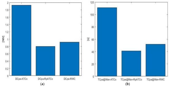
Figure 15.
(a) Mean of the distance between the own RPA and the intruder at the CPA and time to CPA at the Well Clear maneuver execution (b) in the encounters in which the RP maneuvered following: the ATCo separation provision, the RWC system indications in controlled airspace (RpATCo), and the RWC system indications in uncontrolled airspace (RWC).
- The ATCo separation provisions.
- The RWC system indications but asking the clearance of the ATCo (mainly in controlled airspace class E in encounters with VFR intruders).
- The RWC system indications without asking any clearance (i.e., in uncontrolled airspace classes).
It highlights how the RWC system indications do not overlap the ATCo separation provisions that are given long before the other two cases. Those observations are further verified comparing the time to CPA at the Well Clear maneuver execution in Figure 15b.
In all the analyzed cases the timing of the Caution alert issuing was sufficient to coordinate with the ATCo, if needed, and to avoid the Loss of Well Clear, except for only one case in which the RP had difficulties in contacting the ATCo due to the high rate of communications.
Finally, in the performed RTS, we had 15 encounters with intruders equipped with an ADS-B and a TCAS-II system. We had LoWC conditions in seven of those: two due to an AP failure that forced the RP to maneuver too late or to not maneuver at all and five due to accelerated encounters (i.e., intruders executing a maneuver toward the own RPA at a relative low distance and/or high speed). In four of the eight cases in which no LoWC occurred, the RP executed the Well Clear maneuver with a mean of 62 s of tCPA at a mean distance of 3.6 NM following the RWC Caution activation occurring at a mean of 75 s of tCPA at a mean distance of 4.4 NM. The time interval from the Caution alert activation up to the execution by the RP of the Well Clear maneuver did not trigger the RA activation under any circumstances.
A detailed analysis of two conducted encounters follows.
The first test aimed to create a Loss of Well Clear between the RPAS vehicle, in MALE configuration, flying under IFR, and a non-cooperative GA aircraft operating in VFR in the controlled airspace class D. The RPAS was authorized to perform a level surveillance path at 2500 ft, in close proximity of the airport runway, while the GA aircraft is cleared to perform the final approach path to land, descending from 3000 ft to 250 ft. The ATCo is in radio contact with the VFR intruder that is not visible on the CWP.
The encounter conditions occur when the RPAS is descending to reach the surveillance path (Figure 16b) and the GA is approaching the waypoint to align to the runway (Figure 16a). The RWC system activates a Caution alert (Figure 17a) and the RP contacts the ATCo asking for a clearance to execute a left turn maneuver (Figure 16a). During the maneuver, the RWC system reduces the warning level of the intruder to an Advisory alert, indicating to the RP that it is no more a threat given the current navigation state of the own RPARPA but there are still peripheral conflict bands associated with it (Figure 17b). No vertical maneuver is executed by either aircraft involved during the encounter (Figure 16b).
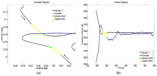
Figure 16.
(a) Horizontal trajectory of the encounter. After the activation of the Caution alert the RP receives a clearance from the controller to execute a left turn maneuver that solves the encounter. (b) Vertical trajectory of the encounter. The RPAS is descending while the intruder is in level flight during the RWC alert activations. No vertical maneuver is executed by either aircraft involved during the encounter.
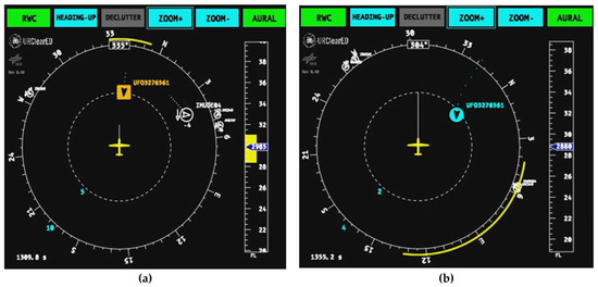
Figure 17.
The CDTI before (a) and after (b) the Remain Well Clear maneuver.
In the analyzed encounter, the RPAS has a speed of 120 kts, while the intruder is flying at 150 kts. Figure 18b shows that the Caution alert is issued at a tCPA of about 70 s at a horizontal distance of 5.3 NM (Figure 18a). The maneuver was executed after the RP had contacted the ATCo and obtained the clearance, which was at a tCPA of 32 s at a 2.5 NM of distance. After the maneuver execution, the minimum value of horizontal distance was equal to 1.5 NM (Figure 18a), well outside the WCV.
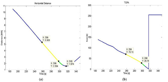
Figure 18.
(a) Relative distance between the RPAS and the intruder during the encounter of Figure 16. The Caution alert activates at 5.3 NM of distance while the RWC maneuver is executed at about 2.5 NM, determining a minimum distance between the aircraft of about 1.5 NM, well outside the Well Clear Volume. (b) Time to closest point of approach during the encounter. The Caution alert activates at 70 s of tCPA giving to the RP the time to contact the controller and receive the clearance to execute the RWC maneuver at about 32 s of tCPA, avoiding the LoWC.
Thus, the Caution alert time of the proposed RWC function was sufficient to contact the controller, receive the clearance, and execute the RWC maneuver, avoiding the LoWC. In detail, the RP confirmed that the workload was low and that the issuing time of the Caution alert was adequate, also considering that he had to call the ATCo more than once due to the busy communication frequency.
Moreover, after the RWC maneuver the Advisory alert, together with the conflict bands displayed on the CDTI (Figure 17b), have kept the RP’s attention on the possible maneuvers that would have again caused a conflict condition.
The next test is characterized by a multi-intruder encounter. The RPAS, in TUAV configuration flying under IFR, is moving in the uncontrolled airspace class G, climbing from 500 ft above ground level to a final level altitude of 5000 ft. A very light piston aircraft flying under VFR and equipped with a Mode A/C transponder is moving from south to north, overtaking the own RPA. At the same time, another aircraft flying under IFR equipped with a Mode A/C transponder is moving from north to south in level flight above the RPAS (Figure 19b) but frontally converging to it (Figure 19a). In these conditions the encounter occurs. The RWC system issues an Advisory alert for the overtaking aircraft, while a Caution alert is issued for the aircraft in a head-on encounter (Figure 20a). The RP, following the indications on the CDTI, executes a right turn (Figure 19a) until only Advisory alerts are displayed on the CDTI (Figure 20b). In this scenario, the ATCo provided only a flight information service, being the encounter is in an uncontrolled airspace.
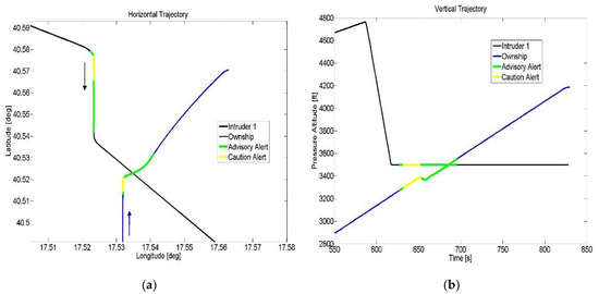
Figure 19.
(a) Horizontal trajectory of the head-on encounter. After the activation of the Caution alert, the RP executes a right turn maneuver supported by the RWC indications on the CDTI, only informing the controller of the executed maneuver as he is flying under an uncontrolled airspace. (b) Vertical trajectory of the encounter. The RPAS is climbing, while the intruder is in level flight during the RWC alert activations. No vertical maneuver is executed by either aircraft involved in the encounter.
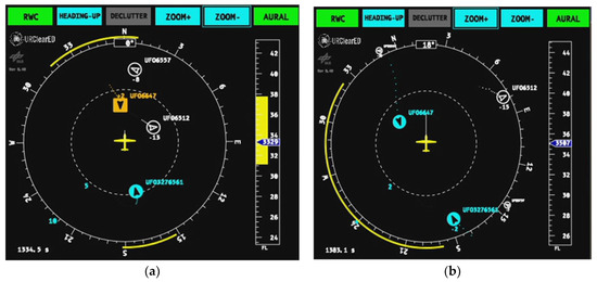
Figure 20.
The CDTI before (a) and after (b) the Remain Well Clear maneuver.
During the encounter, the RPAS had a speed of 66 kts, while the head-on intruder was flying at 120 kts. Figure 21b shows that the Caution alert is issued at about 73 s of tCPA at a horizontal distance of 3.8 NM from the head-on intruder (Figure 21a). The RWC maneuver has been executed at about 55 s of tCPA. In this case, the time interval between the Caution alert activation and the execution of the RWC maneuver is lower with respect to the previous case, as no clearance had to be requested by the RP. After the maneuver execution, the minimum value of horizontal distance is equal to 0.78 NM (Figure 21a), which is outside the defined WCV.
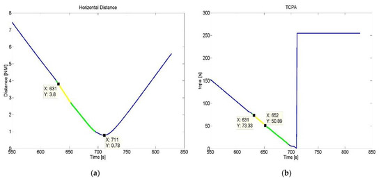
Figure 21.
(a) Relative distance between the RPAS and the head-on intruder during the encounter of Figure 16. The Caution alert activates at 3.8 NM, while the RWC maneuver is executed at about 2.8 NM, determining a minimum distance of about 0.8 NM that is outside the Well Clear volume. (b) Time to closest point of approach during the encounter. The Caution alert activates at 73 s of tCPA, giving to the RP the time to evaluate the conflict, select the RWC maneuver, and execute it at about 55 s of tCPA, avoiding the LoWC.
Additionally, in this case, as confirmed by the RP at the end of the simulation, the issuing time of the Caution alert was adequate to evaluate the conflict, select, and execute the RWC maneuver, also taking into account the forbidden directions due to the overcoming intruder.
5.4. Comparison with DO-365A RWC Alerting
Whereas the Caution alert defined in the URClearED solution is very similar to the Corrective alert defined in RTCA DO-365A, an important difference is the additional Warning alert in DO-365A. This alert, which is issued at the moment a maneuver is required (because otherwise Well Clear conditions will be lost), is intended to inform the pilot about the urgency to maneuver. In an operational environment that does not use a Warning alert, it is to be expected that the time at which a hypothetical Warning alert would be issued is close to the latest time the RPAS pilot implements the maneuver that has been provided by ATCo. For the RTS, this expectation has been checked by comparing the alerting behavior of the URClearED implementation as it occurred during the RTS with the alerting behavior that a DO-365A compliant system would exhibit. To perform this comparison, the recorded own RPA and traffic states from the RTS were converted into the format that the GA-ASI Conflict Prediction and Display System (CPDS) uses and inputted via the LVC configuration [25]. Using a replay tool, the recorded data were provided to the CPDS interface in real time. As such, CPDS did not “know” that the data obtained is from a recording.
The following steps were performed using the replay of the data through CPDS:
- Identification of all encounters with intermittent alerts.
- Identification of all encounters in which an intruder maneuver caused a sudden transition from an alert-free situation to a situation in which Well Clear is lost, i.e., in which no credit can be taken that a DAA alert might have resulted in a pilot maneuver that would have prevented Loss of Well Clear.
- Identification of encounters in which own RPA maneuver occurred during the Corrective alert and no Warning alert was issued.
- Identification of encounters in which own RPA maneuver occurred during the Corrective alert or Warning alert and Loss of Well Clear was avoided.
- Identification of encounters in which own RPA maneuver occurred during the Corrective alert or Warning alert and Loss of Well Clear was not avoided.
For the 28 encounters, a total of 53 CPDS alerts were registered. From these 53 alerting situations, 6 were intermittent Corrective alerts caused by an intruder maneuver that only temporarily caused a predicted Loss of Well Clear within the alerting time range.
Hence, a total of 47 alerts can be considered as a justifiable trigger for pilot action. From these 47 alerting situations, 17 met the conditions that a Corrective alert preceded a Warning alert with sufficient time (there were 14 only warnings, 15 only correctives, leaving 24 with both corrective and warning, of which 17 with sufficient time). In eight of these, no Loss of Well Clear occurred. In the remaining 9, a total of 5 situations had a severity of Loss of Well Clear equal to 10 or below. This leaves four encounters in which a Warning alert may have provided the pilot with a sense of urgency to maneuver, allowing Loss of Well Clear to be prevented. Based on that, the main conclusion is that the Warning alert removed in the URClearED solution is actually not essential for determining the effectiveness of RWC in supporting the RP to solve the conflict, even though some means to indicate to the RP the urgency of performing some action could be helpful.
6. Conclusions
The present paper reports the process followed in the SESAR project URClearED for the definition and implementation of a RWC system to be integrated in unmanned air vehicles flying IFR into airspaces classes D–G. Moreover, the implementation of the Surveillance and Display functions, strictly needed to fully exploit the RWC functionalities, has also been discussed.
The requirements of the RWC system have been extracted at the European level from the ED-258 [11] and integrated with the RTCA DO-365 [15,16] applicable requirements. Results from past and current European projects have been used, and new requirements to fill the gaps with respect to the URClearED objectives have been defined.
The resulting requirements have guided the RWC implementation and the definition of the WCV. The quantification has been made a function of the performance of the RPAS equipped with the RWC system (i.e., TUAV/RUAV or MALE), the type of intruder, in terms of its onboard equipment (i.e., non-cooperative, cooperative without ACAS, and cooperative with ACAS), and the altitude level of the encounter (i.e., above or below the 10,000 ft, where there is a limitation of speed up to 250 kts).
RT hardware and human in-the-loop simulation sessions have been performed with the aim to evaluate the performance of the RWC, the Human–Machine Interface and the interactions between the RP, the ATCo, and the intruder pilot, sharing the responsibility to manage a potential Loss of WC condition within realistic operating conditions in the European airspace classes D–G.
The results of two of the three RT simulation campaigns have been reported in the present work and specifically those concerning the evaluation of the RWC system for fixed-wing RPAS, in both the configuration TUAV and MALE.
At the end of the second RT campaign, the following conclusions have been derived about the proposed RWC system:
- The measured RWC alert timing was sufficient to coordinate with the ATCo, if needed, and to avoid the Loss of Well Clear for all types of intruder equipment and encounter geometries, supporting the RP in the resolution of conflicts in all the tested airspace classes.
- LoWC in nominal conditions has occurred in:
- ○
- Accelerated encounters (i.e., intruders executing a maneuver toward the own RPA at a relatively low distance and/or high speed), which are characterized by a short time of CPA at the Caution alert activation that did not give sufficient time for RP to react.
- ○
- Encounters with non-cooperative intruders due to the limited field-of-view of the non-cooperative traffic sensor onboard the own RPA.
- The RWC systems also demonstrated the desired behavior in multi-intruder encounters tested.
- In encounters with ACAS-equipped intruders, the time interval from the Caution alert activation up to the execution by the RP of the Well Clear maneuver did not trigger the RA activation of the TCAS-II system. This indicates the interoperability of the proposed RWC system with the TCAS-II systems.
- ATCo separation provisions, when available, were well in advance with respect to the RWC Caution alert activation. This indicates the interoperability of the RWC system with the separation service given by ATCo in controlled airspace.
Moreover, the following conclusions have been reached by the discussions with pilots and controllers during the RT simulations:
- All the remote test pilots reported that the implemented system provides a good situational awareness, coherent with the actual traffic dynamical evolution. Specifically, it provides added value with respect to the ATCo information in all tested airspace classes D-E-G;
- In the second RTS, the RP gave a positive feedback on the CDTI that was updated with respect to the first session in order to visualize the traffic information (name of the intruder, flight level, climb/descent indication, zoom level indication) with a greater font size;
- In controlled airspaces D-E, the RP should not call/maneuver autonomously, but having a long-range traffic visibility, through the surveillance function, pilots tended to act in advance with respect to ATCo instructions or the RWC alerts. A recommendation derived from the previous point, is that specific RWC procedures should be defined and the RPs should be adequately trained to use them, before the new tool can be effectively adopted into actual operational environments;
The general consensus was that the RWC system can increase flight safety and can help avoid traffic disruptions due to collision avoidance activation, not only in class G, but also in classes D and E, where VFR aircraft without transponders can be present. It shall be anyway noted that all these benefits are not always guaranteed by the RWC module, as it is evident from the RTS results. Therefore, a Collision Avoidance function shall always be present onboard the RPAS to manage, in an emergency, situations that RWC and RP have been not able to timely resolve.
Moreover, several refinements of the RWC function itself shall be made:
- Further evaluation of the trade-offs between the Caution alert time margins to avoid LoWC and the time margins between LoWC and CA alerts.
- Upgrade of RWC guidance function for accounting limitations in the field-of-view of non-cooperative sensors.
- Upgrade of RWC alerting function to account for maneuverability of intruders.
- Need for detailed RP procedures and related specific training regarding the use of the RWC in the airspace classes D–G, in order to mitigate the risk of bringing the RPs to execute separation with the traffic before calling ATCo.
Author Contributions
Conceptualization, all authors; methodology, all authors; software, G.C., F.C. and N.P.; validation, G.C., U.C., E.F. and F.C.; writing—original draft preparation, G.C., F.C., E.T. and N.P.; writing—review and editing, E.T. and N.P. All authors have read and agreed to the published version of the manuscript.
Funding
 This project has received funding from the SESAR Joint Undertaking (JU) under grant agreement No 892440. The JU receives support from the European Union’s Horizon 2020 research and innovation program and the SESAR JU members other than the Union.
Acknowledgments
The authors would like to thank Enric Pastor from the Universitat Politècnica de Catalunya who supported the definition of the Well Clear Volume, Riccardo Rocchio, Nicola Genito, and Gianluigi Di Capua from CIRA who supported the execution of the real-time simulations.
Conflicts of Interest
The content of this paper reflects only the authors’ views and the SESAR Joint Undertaking is not responsible for any use that may be made of the information it contains. The authors declare no conflict of interest. The funders had no role in the design of the study; in the collection, analyses, or interpretation of data; in the writing of the manuscript, or in the decision to publish the results.
Acronyms
| ACAS | Airborne Collision Avoidance System |
| ADS-B | Automatic Dependent Surveillance-Broadcast |
| AP | Autopilot |
| ATCo | Air Traffic Controller |
| ATM | Air Traffic Management |
| C2L | Command and Control Link |
| CA | Collision Avoidance |
| CDTI | Cockpit Display of Traffic Information |
| CPA | Closest Point of Approach |
| CPDS | Conflict Prediction and Display System |
| CWP | Controller Working Position |
| DAA | Detect And Avoid |
| FMS | Flight Management System |
| FTS | Fast Time Simulation |
| GA-ASI | General Atomics – Aeronautical Systems |
| GNC | Guidance Navigation and Control |
| HK | Housekeeping |
| HMD | Horizontal Miss Distance |
| HMI | Human Machine Interface |
| HP | Human Performance |
| HST | Horizontal Spatial Threshold |
| HTT | Horizontal Temporal Threshold |
| IFR | Instrumental Flight Rules |
| ISF | Integrated Simulation Facility |
| LAT | Look Ahead Time |
| LoWC | Loss of Well Clear |
| MALE | Medium Altitude Long Endurance |
| MFD | Multifunctional Flight Display |
| MOPS | Minimum Operational Performance Standards |
| NMAC | Near Mid Air Collision |
| OSED | Operational Services and Environment Definition |
| PFD | Primary Flight Display |
| RA | Resolution Advisory |
| RP | Remote Pilot |
| RPA | Remotely Piloted Aircraft |
| RPAS | Remotely Piloted Aircraft System |
| RPS | Remote Pilot Station |
| RT | Real Time |
| RTS | Real-Time Simulation |
| RUAV | Rotorcraft Unmanned Aerial Vehicle |
| RWC | Remain Well Clear |
| TAS | Active Surveillance Transponder |
| TCAS-II | Traffic Collision Avoidance System-II |
| TUAV | Tactical Unmanned Aerial Vehicle |
| UAV | Unmanned Aerial Vehicle |
| VFR | Visual Flight Rules |
| VST | Vertical Spatial Threshold |
| WCV | Well Clear Volume |
References
- European RPAS Steering Group. Roadmap for the Integration of Civil Remotely-Piloted Aircraft System; European Union: Brussels, Belgium, 2013. [Google Scholar]
- Federal Aviation Administration. Integration of Civil Unmanned Aircraft Systems (UAS) in the National Airspace System (NAS) Roadmap, 2nd ed.; FAA: Washington, DC, USA, 2018.
- Pastor, E.; Peinecke, N.; Theunissen, E.; Corraro, F.; Shaw, C.; Taurino, D.; Hagstrom, P. URClearED–Defining the Remain Well Clear Concept for Airspace D-G Classes in the European Airspace. In Proceedings of the AIAA Aviation Forum, Virtual Event, 2–6 August 2021. [Google Scholar]
- ICAO Annex2. Rules of the Air, 10th ed.; ICAO: Montreal, QC, Canada, 2005. [Google Scholar]
- EASA. Easy Access Rules for Standardised European Rules of the Air (SERA)—Part A; EASA: Cologne, Germany, 2022.
- Upchurch, J.M.; Munoz, C.A.; Narkawicz, A.J.; Chamberlain, J.P.; Consiglio, M.C. Analysis of Well-Clear Boundary Models for the Integration of UAS in the NAS; NASA Technical Memorandum: Hampton, VA, USA, 2014.
- Cook, S.P.; Brooks, D.; Cole, R.; Hackenberg, D.; Raska, V. Defining Well Clear for Unmanned Aircraft Systems. In Proceedings of the AIAA Infotech at Aerospace Conference, Kissimmee, FL, USA, 5–9 January 2015. [Google Scholar]
- Comstock, J.R.; Ghatasm, R.W.; Vincent, M.J.; Consiglio, M.C.; Munoz, C.A.; Chamberlain, J.P.; Volk, P.; Arthur, K.E. Unmanned Aircraft Systems Human-in-the-Loop Controller and Pilot Acceptability Study: Collision Avoidance, Self-Separation, and Alerting Times (CASSAT); NASA Technical Memorandum: Hampton, VA, USA, 2016.
- Fern, L. SC-228 Inclusion of DAA Warning Alert for TCAS Interoperability; NASA Technical Reports: Washington, DC, USA, 2016.
- Williams, K.W.; Caddigan, E.; Zingale, E. An Investigation of Minimum Information Requirements for an Unmanned Aircraft System Detect and Avoid Traffic Display; FAA: Washington, DC, USA, 2017; Technical Report DOT/FAA/AM-17/14.
- EUROCAE ED-258; Operational Services and Environment Description for Detect and Avoid [Traffic] in Class D-G Airspaces under VFR/IFR. EUROCAE: Saint-Denis, France, 2019.
- SESAR Joint Undertaking. P.J. 13-Solution 111. Operational Service and Environment Definition (OSED); SESAR JU: Brussels, Belgium, 2020. [Google Scholar]
- MIDCAS. Final Technical Presentation of Task 2.5; MIDCAS Final Workshop: Brussels, Belgium, 2015. [Google Scholar]
- European Detect and Avoid (DAA) Function Based on New Sensors and Processing for RPAS Integration into Air-Traffic Management (EUDAAS). Available online: https://ec.europa.eu/commission/presscorner/detail/en/fs_20_1082 (accessed on 19 September 2022).
- RTCA DO-365; Minimum Operational Performance Standard (MOPS) for Detect and Avoid (DAA) Systems. RTCA: Washington, DC, USA, 2017.
- RTCA DO-365; Minimum Operational Performance Standard (MOPS) for Detect and Avoid (DAA) Systems. Revision A. RTCA: Washington, DC, USA, 2020.
- ICAO Annex 11. Air Traffic Services, 13th ed.; ICAO: Montreal, QC, Canada, 2001. [Google Scholar]
- RTCA. RTCA-DO-185B—Minimum Operational Performance Standards for Traffic Alert and Collision Avoidance System (TCAS II) Airborne Equipment—Change 2; RTCA: Washington, DC, USA, 2013. [Google Scholar]
- Commission Regulation (EU). Laying down Common Airspace Usage Requirements and Operating Procedures for Airborne Collision Avoidance; European Union: Brussels, Belgium, 2011. [Google Scholar]
- Howell, R.; Hutchinson, H.; Morton, O.T. CAFE: Encounter Generator Tool (EGT)–Software Design Document (SDD); EUROCONTROL: Brussels, Belgium, 2018. [Google Scholar]
- EUROCONTROL. Guidelines for Short Term Conflict Alert Part III—Implementation and Optimization Examples; EUROCONTROL: Brussels, Belgium, 2017. [Google Scholar]
- Munoz, C.; Narkawicz, A.; Hagen, G.; Upchurch, J.; Dutle, A.; Consiglio, N. Daidalus: Detect and avoid alerting logic for unmanned systems. In Proceedings of the 34th Digital Avionics Systems Conference (DASC), Prague, Czech Republic, 13–17 September 2015. [Google Scholar]
- RTCA DO-257B; Minimum Operational Performance Standards for the Depiction of Navigational Information on Electronic Maps. RTCA: Washington, DC, USA, 2018.
- Genito, N.; Montemari, F.; Palumbo, R.; Rispo, D.; Corraro, G.; Canzolino, P. Integrated simulation facility for interoperability operation. Lect. Note Comput. Sci. 2014, 8906, 105–121. [Google Scholar]
- Theunissen, E.; Kotegawa, T. Applying LVC to Testing and Evaluation of DAA Systems. In Proceedings of the 36th Digital Avionics Systems Conference (DASC), St. Petersburg, FL, USA, 17–21 September 2017. [Google Scholar]
Publisher’s Note: MDPI stays neutral with regard to jurisdictional claims in published maps and institutional affiliations. |
© 2022 by the authors. Licensee MDPI, Basel, Switzerland. This article is an open access article distributed under the terms and conditions of the Creative Commons Attribution (CC BY) license (https://creativecommons.org/licenses/by/4.0/).