Abstract
Radical innovations for all aircraft systems and subsystems are needed for realizing future carbon-neutral aircraft, with hybrid-electric aircraft due to be delivered after 2035, initially in the regional aircraft segment of the industry. Electrical energy storage is one key element here, demanding safe, energy-dense, lightweight technologies. Combining load-bearing with energy storage capabilities to create multifunctional structural batteries is a promising way to minimize the detrimental impact of battery weight on the aircraft. However, despite the various concepts developed in recent years, their viability has been demonstrated mostly at the material or coupon level, leaving many open questions concerning their applicability to structural elements of a relevant size for implementation into the airframe. This review aims at providing an overview of recent approaches for structural batteries, assessing their multifunctional performance, and identifying gaps in technology development toward their introduction for commercial aeronautic applications. The main areas where substantial progress needs to be achieved are materials, for better energy storage capabilities; structural integration and aircraft design, for optimizing the mechanical-electrical performance and lifetime; aeronautically compatible manufacturing techniques; and the testing and monitoring of multifunctional structures. Finally, structural batteries will introduce novel aspects to the certification framework.
1. Introduction
The necessity to unite environmental sustainability and economic growth is a major challenge for the aviation industry [1]. These needs resulted in policy roadmaps in Europe and the US [2,3,4], and led to consistent long-term research efforts. In 2019, the European Green Deal [5] set the ambitious goal of achieving climate neutrality in all sectors of the EU economy, including air transport, by 2050, raising the bar significantly above the previous environmental targets.
One of the main strategies to limit in-flight emissions of greenhouse gases (GHG) and pollutants is the increased use of electrical energy onboard aircraft for both non-propulsive (e.g., secondary systems) and propulsive purposes, leading to the concepts of “more electric aircraft” (MEA), “hybrid electric aircraft” (HEA) and “all-electric aircraft” (AEA). In addition, the electrification of aircraft may result in lower operative and maintenance costs, and may open new markets that are not served with conventional aircraft, such as urban air mobility with electric vertical take-off and landing vehicles (e-VTOL) [6]. The use of electrical energy is at the same time a key enabler, i.e., benefiting from the highly energy-efficient electric drive train, enabling distributed electric propulsion concepts, and also a limiting factor toward the large-scale introduction of electrified aircraft, due to the limited energy and power density of current battery technologies, thus introducing a substantial weight penalty.
An alternative approach to storing electrical energy in a conventional battery system installed in the aircraft is to combine energy storage and load-bearing capabilities in multifunctional structures, or structural batteries (SB), which have come to the forefront of research since the late 1990s.
After this introduction, Section 2 discusses the latest research on structural batteries, with the different approaches undertaken and considerations according to the level of integration, as well as the manufacturing of structural battery cells; Section 3 reviews their integration into composite structures, including structural materials, manufacturing processes, integration strategies and the testing of SB; Section 4 reviews the certification framework that is likely to apply to SB; Section 5 and Section 6 look at first studies on structural batteries integration at aircraft level and collect expectations and first recommendations made by aeronautic industry experts. Finally, Section 7 evaluates the state of current approaches versus 2030+ aeronautic targets, while Section 8 aims to give recommendations for developing further structural batteries for aeronautic applications.
2. Research into the State of the Art of Structural Battery Approaches
2.1. Classification and Performance Metrics
Structural batteries or multifunctional electrochemical energy storage systems combine energy storage capabilities, like conventional lithium-ion (Li-ion) batteries, with the mechanical properties of composite materials like carbon-fiber-reinforced polymers (CFRPs). They can be classified into different categories depending on their degree of structural integration. This review adopts a convenient 5-class system, introduced in [7] and shown in Figure 1, starting from a side-by-side combination of a structural element and a conventional battery (zero degrees of integration) and increasing the degree of integration from integrating battery cells into structural components (type I), thin-film approaches (type II), up to a fully integrated system, for which the structural element (type III) or material (type IV) also functions as an energy storage unit.
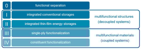
Figure 1.
Classification system of structural batteries, adopted from [7].
Structural batteries can be also grouped into two additional categories, namely, multifunctional structures (or decoupled systems) and multifunctional materials (or coupled systems). In the former, different materials fulfill only one function (either energy storage or load-bearing); however, the overall composite is multifunctional. In the latter, all materials adopt multiple functions (i.e., energy storage and load-bearing). Thus, multifunctional structures are synonymous with type-I and type-II structural batteries, whereas multifunctional materials include type-III and type-IV structural batteries [8].
A simple approach to evaluate the performance of structural batteries has been proposed by Synder et al. [9,10]:
where is the overall multifunctional efficiency of the structural battery, consisting of the electrochemical efficiency and the structural efficiency . The electrochemical efficiency () represents the ratio of the electrochemical performance of the multifunctional material/structure () and a non-structural reference system (), whereas represents the ratio of the specific moduli of the multifunctional material/structure () and a purely structural reference system (), or, in the case of multiple relevant performance indicators, the minimum of their ratios. The structural battery yields an improvement against the non-integrated reference and, thus, a relative weight reduction, only for .
The approach represented by Equation (1) is simple but quickly provides an initial generalized basis for comparing at a materials level the different approaches, as presented in Section 7. Equation (1) can be generalized into a more advanced, but application-specific metric, defined by a value function:
with weightings and performance indicators , one that is minimized by balancing the conflicting objectives with well-tuned weightings. For SB integration into complex structures and components, the application-specific design degrees of freedom from material to element levels, and trade-offs would need to be considered.
The evaluation of the electrochemical performance of structural batteries usually uses straightforward parameters as performance indicators, such as specific energy or gravimetric energy density (in Wh/kg), volumetric energy density (in Wh/L), or specific power (in W/kg). In some cases, the exact material for which data are reported is not explicitly stated (all, only active, etc.), making comparative analyses of data difficult. However, reasonable assumptions can usually be made from the complementary data provided. On the other hand, the evaluation of the mechanical capabilities of structural batteries takes more effort because applied testing methods are usually closely related to the envisioned application. As such, a large variety of different mechanical properties are reported, among them: elastic modulus [11,12,13,14,15,16], tensile strength [11,14], bending modulus [16], stiffness [17,18], performance under compressive stress [19], tensile stress [20], compression modulus [21], and shear modulus [22]. This considerably complicates any comparison between different studies. However, the elastic modulus is recently becoming an accepted representative of the overall structural performance of the structural battery [11,23]. For aeronautic applications, additional mechanical properties should be considered, e.g., the onset of damage or the strengths for different loadings, such as bending or compression. Common performance indicators for the evaluation of structural batteries are compiled in Figure 2.
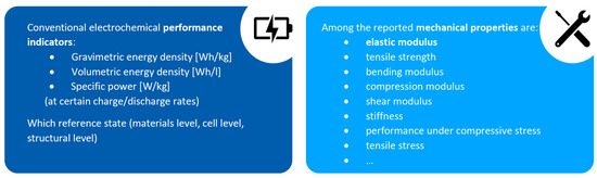
Figure 2.
Common parameters for evaluation of structural batteries.
2.2. Summary of the State of Art for Structural Batteries
This section summarizes structural battery approaches reported in the literature from 2002 to 2021, according to the classification system introduced in Section 2.1. Beforehand, recent general reviews are summarized.
Asp et al. [24] review the most recent works on SB as multifunctional materials (types III and IV), without reference to a particular application. Data and research experiences on carbon fibers as negative electrodes and composite polymer electrolytes, tested in half-cells, are gathered. The authors conclude that the technology presents no clear showstoppers, due to recent advancements in structural electrolytes. Nonetheless, incomplete data on complete cells are available, due to the unavailability of structural positive electrodes. This impacts the information available for simulations, manufacturing scalability, lifecycle and recycling. Danzi et al. [25] published a comprehensive review on structural batteries that covers materials for anodes, cathodes, manufacturing techniques and tests, again not focusing on specific applications. On top of presenting existing research on electrode cells and embedded Li-ion batteries, Kalnaus et al. [26] describe approaches toward designs focused on safety (features to improve the resistance of SB to damage or to prevent thermal runaway). The work also lists the more significant research gaps: the creation of structural electrolytes with high ionic conductivity; the improvement of mechanical performance after cycling; the execution of extensive testing programs for various load conditions; the research on the system-level requirements of SB (thermal management, electrical connections).
2.2.1. Functional Separation (Type 0)
Structural batteries need to compete against a classical, functionally separate system of commercial batteries and conventional load-bearing elements. Currently, consistent research efforts are dedicated to increasing the energy density of current Li-ion batteries, which lies in the region of 260 Wh/kg and 700 Wh/L at cell level (e.g., Panasonic NCR18650B cylindrical Li-ion cells) [27].
CFRP composites are usually considered as most suitable for load-bearing components. They provide an elastic modulus of around 130–340 GPa for unidirectional (UD) fibers and around 70–90 GPa for fabrics, a compression strength of around 800–1600 MPa (UD) and 700–800 MPa (fabrics), a shear modulus of 4–5.5 GPa and in-plane shear strengths of 80–95 MPa (average composite properties with 60% fiber volume, data compiled from [28,29]).
2.2.2. Integrated Conventional Storage (Type I)
The integration of commercial Li-ion batteries into a dedicated structural element, as shown in Figure 3, presents the lowest degree of multifunctionality. It was the first [30] and remains the most widely investigated approach. Considered applications are unmanned vehicles [30,31,32], the automotive industry [21], aeronautic industry [33], and maritime sector [18], as well as for space technology [17,34,35], especially microsatellite applications [36,37].
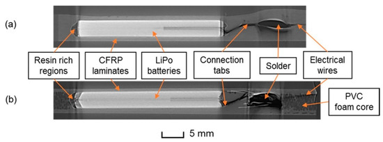
Figure 3.
Examples of integrated conventional storage: cross-sectional X-ray CT images of an embedded LiPo pouch cell in (a) CFRP laminate and (b) sandwich composite [38].
The low multifunctionality of this type of structural battery limits the savings in mass, often restricted to the weight of the casing/packaging, which is often replaced by a mechanically reinforcing material like CFRP to increase the degree of multifunctionality [7]. Attempts to further increase the structural capabilities of the composite include modifications of the batteries themselves by introducing, e.g., rivets [39,40,41,42,43] or perforations filled with epoxy [44]. On the other hand, feasible processing and the availability of cheap components (i.e., battery cells) render this approach the most cost-effective, although Roberts et al. [17] stated that the beneficial effects of structural batteries might be offset by the additional cost of manual or semi-automatic manufacturing of battery designs tailored for integration into structural parts. This issue has already been mentioned in the early works of Thomas et al. [31], who identified the procurement of custom-made battery cells as the bottleneck of this approach.
The mechanical and electrochemical performance of type-I structural batteries depends on how many battery cells are incorporated per unit of area. An observed general trend is that the more batteries are incorporated, the higher the achieved energy density [45], but the lower the mechanical properties [30,38,43]. This is expected, as some of the mechanically reinforcing material with a high tensile modulus (around 50 GPa) is removed to fit the battery cells with a low modulus (around 150 MPa, i.e., ~330 times lower) in the structural composite [38]. Therefore, the main challenge remains to provide a proper balance between the reduction of mechanical properties and the achievable energy density. A common reference value for the electrochemical performance of type-I structural batteries was established by Thomas et al. [18], who set a goal of 50 Wh/l for marine systems applications. To reach this target, a reduction of the specific mechanical properties of around 40% for laminate composites and 25–30% for sandwich composites can be expected [38,46]. In addition, it was shown that different mechanical properties, like tension, bending, and compression, are differently affected by the incorporation of battery cells into a structural sandwich element [47] and that the impact is largest on the compressive properties.
With type-I approaches, gravimetry energy densities of between 20 and 139 Wh/kg (and volumetric energy density of between 20 and 276 Wh/L) could be achieved, the maximum being realized by integrating custom-made planar multi-electrode pair cells, with conventional-production NMC and graphite active materials and electrodes with organic liquid electrolyte, that were reinforced with rivets as a sandwich structure into CFRP face sheets [43].
The weight savings gained by this approach, compared to functional separation, will become less relevant as battery processing technologies improves. The relative amounts of passive components (like the casings) in conventional batteries are more and more reduced by employing advanced battery-processing methods (e.g., thicker electrode coatings) and optimizations of the cell design (e.g., the recent development of 21,700 cylindrical cells compared to 18,650 cells [48]).
2.2.3. Integrated Thin-Film Energy Storage (Type-II)
Integrating thin-film batteries rather than conventional cells into structural elements has the advantage of minimizing the impact of the battery on the mechanical properties of the composite. Examples of type-II concepts are shown in Figure 4. Unfortunately, the obtainable energy density is quite limited, with reported values in the range of 10–1000 µAh/cm2. Average discharge voltages of around 3.5 V and energy densities of only 35–3500 µWh/cm2 can be expected. In addition, thin-film batteries are significantly more expensive than conventional cells [18], increasing the total cost of the structural composite. Planar [49] or coaxial [50] configurations have been performed and tested, with applications mainly focused on spacecraft appliances.

Figure 4.
Examples of type-II structural batteries: planar [49] (left) and coaxial configurations, after [50] (right).
This renders the class of “integrated thin-film energy storages”, i.e., type II, not fit for large-scale aeronautic application and is, therefore, not considered further in this review. However, a concise summary of type-II approaches is given in [18].
2.2.4. Single-Ply Functionalization (Type III)
Type-III structural batteries represent the first step toward true multifunctionality. The basic idea behind this approach is to substitute as many elements as possible of a conventional battery cell, especially the passive ones (i.e., the casing, current collectors, separator, and electrolyte), with load-bearing elements, as shown in Figure 5.
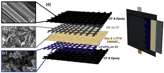
Figure 5.
Example of a type-III structural battery [20].
Promising substitutes can be found for most of the components, except for the cathode material. Therefore, the cathode is usually prepared from either conventional laminate electrodes [11] or functionalizing carbon fibers with active materials like LiFePO4 [51,52].
Carbon fibers can be used for the anode, as they show similar performances as conventional graphitic materials [53]. However, volumetric changes, leading to elongations of up to 1% and 10% in both the longitudinal and transverse directions are observed [54]. Carbon fiber weaves and cloths have also been employed for anodes [52,55], showing, in general, lower performance than spread single fibers [52,56]. To mitigate these issues, coated or functionalized fibers can be employed [54].
The polyolefine separator usually encountered in conventional Li-ion batteries is replaced with a glass-fiber separator, either as a filter-like material or a weave [11,20]. Due to the increase in thickness (by a factor of 3 to 10) and in density (by a factor of around 2.8) of the separator and of the increased amount of stored electrolyte, the gravimetric energy density of the cell decreases up to a factor of 4 (estimated with data from [57]).
The electrolyte is one of the most crucial components for type-III structural batteries. Conventional liquid carbonate electrolytes are still employed due to the lack of alternative highly conducting electrolytes with good mechanical and structural properties. Reports on polymer and co-polymer electrolytes showed that a mono-phasic electrolyte cannot satisfy both high load-bearing and high ion conductivity requirements. Therefore, biphasic or bicontinuous structural electrolytes are used. These comprise a load-bearing component, usually an epoxy-based polymer/resin matrix, and an ionically conductive component, which is either a conventional liquid electrolyte or an ionic liquid electrolyte [58,59,60,61].
One of the advantages of type-III structural batteries, apart from higher mass savings due to their higher degree of multifunctionality, is the feasible processing of the different components. Conventional methods like tape casting [15] or vacuum-assisted resin transfer molding [62] can usually be applied for the preparation of the battery cells. However, substantial research efforts are still needed to develop the different multifunctional components and full structural battery assemblies.
Working type-III structural batteries have shown specific energies of between 12 and 58 Wh/kg and elastic or tensile modulus in the GPa range (see the references within this section).
2.2.5. Constituent Multifunctionalization (Type IV)
For type-IV structural batteries, as depicted in Figure 6, different setups were proposed; these can be classified into coaxial [63,64,65] and layered approaches [22,66,67].
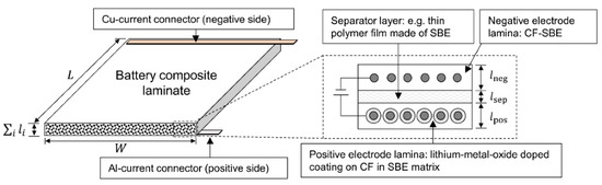
Figure 6.
Example of a type-IV structural battery concept [66].
The coaxial approach envisions a fiber-shaped battery, which is composed of a carbon-fiber core onto which an electrolyte layer is deposited; afterward, the fibers are immersed into a matrix acting as the cathode material [63,64,65].
In the layered approach, carbon fibers act as the anode material as well, with coated carbon fibers acting as the cathode material. They are aligned to form electrode bands, separated by a thin layer of electrolyte [22,66,67].
Research has primarily focused on the development of the different components. No functional full cell of a type-IV structural battery offering significant energy storage and load-bearing capabilities has yet been demonstrated. However, some recent publications showed proof-of-concept-type cells: a coaxial, type-IV micro-battery was developed by Thakur et al. [13], who used a continuous carbon fiber coextrusion method to produce battery filaments. The use of a liquid electrolyte, as well as a great deal of insulating photopolymer (which increases the passive weight), resulted in negligible mechanical as well as electrochemical performance.
Asp et al. [11] recently assembled a structural battery using the layered approach, with carbon fiber acting as an anode and either a Whatman glass microfiber separator or two 0°/90° woven GF fabrics as the separator. They obtained meaningful energy density and structural properties, i.e., 11.6 or 23.6 Wh/kg @ 0.05 C and an elastic modulus of 18 or 25 GPa, although the use of a conventional laminate LiFePO4 cathode would qualify this approach as closer to a type-III battery.
Performance evaluations and possible shortcomings of type-IV cells have been studied with analytical and numerical models: an inverse relationship between the shear modulus and the achievable energy density has been predicted [22]. Energy densities of around 146 Wh/kg @ C/10 are expected, assuming NMC622 and CF as active materials and a separator thickness of 25 µm, but reducing the elastic properties of the composite by approx. 50% in a longitudinal direction and by 80–90% in a transverse direction [63,64].
The potential of type-IV batteries for use in different vehicles, including aircraft, has also been estimated: for an interior-foam-core sandwich panel, commonly found in commercial aircraft, a potential mass saving of 4% was stated when functionalizing the CFRP face sheets with a full-layer, single electrode-pair structural battery [68].
2.2.6. Structural Batteries Using Different Cell Chemistries (Other Than Li-Ion)
Cell chemistries other than lithium-ion (such as LiFePO4 or NMC) have been employed to realize structural batteries. Among them are Ni-Fe [14] or Zn-MnO2 [69], Zn-air and Ni-Fe aqueous batteries, which are safer than lithium-ion ones [23,70].
2.3. Considerations for the Manufacturing of Structural Battery Cells
Type-I and type-III/IV structural battery approaches have very different requirements concerning their production. This section links the established Li-ion battery cell production with the needs of structural batteries. Type-I concepts share similarities to established battery cell production, i.e., by manufacturing cell stacks of electrodes, separators and electrolytes and later integrating them into structural elements. The stacking process is already industrially established in the field of pouch cell design. Two major differences to the industrially established Li-ion batteries will influence the production process of structural batteries: the use of a structural, (quasi-)solid-state electrolyte and the housing/casing of the cell stacks.
For conventional pouch cells, the process chain of the current manufacturing process, as shown in Figure 7, is generally divided into three sections: electrode manufacturing, cell assembly and finishing.
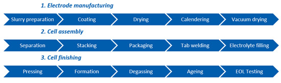
Figure 7.
Process chain of conventional pouch cell production.
For type-I concepts, the electrode production would not require significant changes from the current industrial process, as wet-chemically-manufactured electrodes could be produced via an already established process. Adaptations would possibly be needed with respect to the specific cell chemistry.
Most processes could also be adapted for the cell assembly, with some changes in the details. The challenges that appear in the subsequent drying, winding and separation processes would need to be investigated in more detail. The use of a structural, quasi-solid-state electrolyte would eliminate the electrolyte filling process. The electrodes would then best be coated before electrode separation as this step could be efficiently carried out on the roll. As conventional pouches are mechanically sensitive, structural casing alternatives that can be integrated into the structural element seamlessly need to be considered. Laminates have been proposed as a casing around the stack, e.g., by Thomas et al. [18], using carbon glass composite stabilized with styrene foam and epoxy glue directly applied to the cells to improve adhesion, or by Ladpli et al. [43], who suggested using carbon fiber composites with reinforcement pins for lamination. In the latter approach, the cell stack has recesses to accommodate the pins. For industrial applications, the question remains whether these cut-outs should be created before or after stacking.
As the process steps for cell finishing are mainly determined by the cell chemistry, no substantial differences are to be expected. The stability of the housing may be of concern for transport from battery production to structural integration (which most likely will be performed on different sites). If safety issues would arise here, cell finishing could be carried out after transport.
For type-III/IV structural battery concepts, using (coated) carbon fibers as electrodes and structural electrolytes, scalability of their production would be the main question. Electrophoretic deposition and emulsion polymerization are already industrially established processes. However, their interplay and scale-up would need to be evaluated in the context of structural batteries.
The process chains for both type-I and type-III/IV concepts appear to be scalable at first glance. Already established cell production processes can be used for type-I concepts, with adaptations as demanded by the chosen materials and designs. Processes that are already used industrially elsewhere are proposed for type-III/IV concepts but these still need to be developed in detail.
3. Structural Integration
In this section, the state of the art of structural batteries is assessed from the perspective of integrating electrical energy storage within aeronautical composite structures, considering: (i) the choice of the elementary constituents, (ii) the associated manufacturing processes, (iii) the integration strategies and the considered structures, and finally, (iv) the different kinds of mechanical tests applied to structural battery composites.
3.1. Choice of Elementary Constituents and Architecture
The choice of the elementary constituents for structural battery composites is critical for the battery’s mechanical properties but must be also compatible with the manufacturing process of the battery materials. Here, composite materials constituted with fibers embedded in a polymer matrix are considered.
Carbon fibers are mostly used as a way to obtain high mechanical properties for the composite components. The carbon fibers considered in the literature are T300, UMS50, T800H, IMS65, UMS45, as summarized in [71]. For type-III and type-IV structural battery concepts employing individual carbon fibers as an anode, the IMS65 fibers (strength 6 GPa, modulus 290 GPa) are widely used [67,72] as well as the rather older-generation T300 fibers (strength 3.5 GPa, modulus 230 GPa) [43,73], because they both present an interesting trade-off between rigidities/strengths in the fiber direction and specific capacity, as reported in Figure 8. Additionally, they could be subjected to different treatments to improve their mechanical properties, especially the adhesion between the matrix and fibers.
Figure 8.
Mechanical properties and specific capacity of (a) IMS65, (b) T800H carbon fibers [74].
Type-III concepts are mostly constituted of 2D woven composites [43,74,75], as reported in Figure 9, mainly with twill or satin architectures that are commonly found for automotive applications and that allow the easy manufacturing of complex shapes. Multi-layered composites with 0° and 45° 2D-woven plies have been considered in order to obtain interesting properties not only for tension/compression in the warp and weft directions but also for in-plane shear loading (due to ±45° plies).

Figure 9.
Representation of 2D-woven composite material: 2 × 2 twill architecture for the anode and cathode [71] (a), and laminate unidirectional glass fiber plies with an embedded LATP (solid-state electrolyte) pellet, adapted from [7] (b).
Moreover, laminated unidirectional plies can be used [7,67,76] in order to obtain higher compressive strength than 2D woven composites, which is a critical point for aeronautical applications. In methods proposed by Asp et al. [76], and by Adam et al. [7], simple cross-ply laminates [0°/90°], closely related to 2D woven composite architecture, have been considered, as reported in Figure 9b.
The matrix associated with the fibers not only needs to have a high adhesion with carbon fibers, its curing cycle must also be compatible with the battery materials’ maximum allowable temperature, e.g., PVDF (Polyvinylidene fluoride, used as a binder in the battery electrodes) has a melting point of 177 °C. Therefore, thermoset epoxy matrices with curing temperatures below 170 °C are most commonly considered, such as bisphenol-A [43], an MTS57 [73] matrix, or epoxy resin based on Araldite LY556/hardener XB3473 [77]. Epoxy matrices are also relevant for use with the resin transfer-molding (RTM) process (involving the injection of a liquid matrix) and, thus, are well adapted to 2D-woven composite structures with complex shapes.
High-performance thermoplastic matrices cannot be used, as their processing temperatures of 330 °C and above (e.g., for PAEK (polyaryletherketone), PEKK (polyetherketoneketone) or PEEK (polyetheretherketone)) are way above the maximum temperature tolerated by the battery materials. Thus, no study using these materials is found in the literature.
The material chosen for the interface of the battery cell (e.g., copper or aluminum foil) with the carbon fiber is also important, i.e., carbon-coated copper foils are used to avoid galvanic corrosion [76,78].
3.2. Manufacturing Process
The manufacturing process is generally performed using a vacuum bag for pre-compaction, and the curing is performed at low temperature and low pressure. In the study by Ladpli et al. [43], the composite plate (2D-woven plies) is cured at ambient temperature for 24 h, and post-cured at 90 °C for a few hours after that. For Carlson [75], the maximal temperature applied during the curing cycle is 120 °C or 150 °C, respectively, and the composite part is embedded in a vacuum bag, as reported in Figure 10a. Curing at a low temperature requires increasing the curing duration or applying a post-curing process to obtain the same polymerization state.
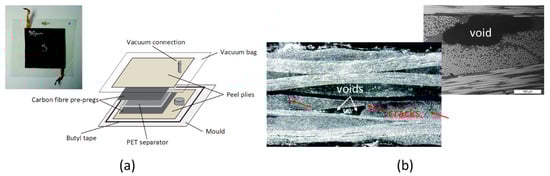
Figure 10.
Manufacturing process with a vacuum bag and low-temperature curing (a), voids observed after the manufacturing process and possible interaction with cracks during the loading (b), adapted from [75].
It is important to note that, typically, a low level of pressure has been applied (about 1 bar) during the curing cycle. However, curing composite parts at low pressure may result in the formation of voids, as reported in Figure 10b, that generate transverse cracks or delamination, decreasing the rigidity and strength of the composite part. This is clearly an issue for aeronautical applications.
Composite plates for aeronautical applications are usually manufactured with an autoclave, where the pressure (up to 7 bars) and the temperature (<180 °C) can be controlled. The application of a higher level of pressure could be an issue for any liquid phase of the structural battery (e.g., liquid electrolyte), which may be pressed out into the composite part. However, the autoclave curing of structural batteries has not been reported so far.
3.3. Integration Strategies and Considered Structures
This section reviews proposed methodologies for integrating battery cells within composite structures, aiming at a minimum degradation of the structural mechanical properties (stiffness and strength). Most of the studies [8,43,68] integrated the battery cells into sandwich-like material constituted of two composite skins and a core (the actual battery cell), as reported in Figure 3 and Figure 11a. With this integration strategy, only plain plates with large dimensions have been manufactured and characterized to determine how the introduction of a battery cell influences the mechanical performance of a composite structure.

Figure 11.
Sandwich-like composite material with a core battery cell [43] (a), rectangular-shaped supercapacitor cells introduced into a large L-angle composite specimen [79] (b), and a supercapacitor LATP pellet of cylindrical shape introduced into a flat composite panel (adapted from [7]) (c).
For large structures, the battery cells can be considered as inserts within composite parts [43,78] with a rectangular shape (with smooth corners to limit stress concentrations in [78] or with sharp ones [43]), similar to the S80 Bootlid demonstrator, as reported in Figure 11b, conceived for the automotive industry, but that includes large and thin (200 × 300 × 2 mm3) supercapacitors as electrical energy storage. Multi-layer battery cells of the type shown in Figure 11a, with dimensions of 200 × 50 × 25 mm3, have been introduced into a very thick structural I-beam, typically used for civil engineering applications [43].
One alternative, proposed by Adam et al. [7], consists of introducing a cylindrical insert into a composite plate with a thickness that equals the thickness of a block of unidirectional plies, in order to reduce stress concentration around the insert and limit damage, as reported in Figure 11c. The pellet is about 10 mm thick with a diameter of around 100 mm, consists of a solid (LATP) electrolyte, and works as a supercapacitor, not as a battery. Only plain plates with a single pellet located at the center of the specimen have been realized.
As per the authors’ knowledge, no published study has considered the optimization of the shape, size, or position of an SB cell within a composite plate. More importantly, there are no studies available on how to introduce and optimally distribute SB cells within (aeronautic) composite structures, aiming at limiting the degradation of mechanical properties due to SB introduction.
3.4. Mechanical Testing
The mechanical tests applied to the composite parts, including battery cells, have been designed to measure the decrease in mechanical properties and the electrical performance of the battery cell. Performing quasi-static tests is preferred for their simplicity and for the limited quantity of composite material required.
In order to determine the decrease in the out-of-plane shear strength due to the introduction of a battery cell, three-point bending tests have been widely performed [43,68,75,80]. An interlaminar shear strength (ILSS) test, based on European standards [81], with a ratio length between the support span over the thickness of the plate that is equal to 5 is widely used, as reported in Figure 12a. The typical dimensions of the tested specimens are about 300 mm × 25 mm. For this test, the bending rigidity and the failure load have been carefully studied. The introduction of pins into the battery cell (see Figure 11a) has been proposed by Ladpli et al. [43] to increase the shear rigidity and strength of the tested composite plates.

Figure 12.
Mechanical tests mostly applied for structural batteries: Short span three-point bending test (a), four-point bending test on plain plates (b) and tensile test on plain coupons (c) [7].
The influence of the introduction of a battery cell on the bending rigidity and the failure load is studied via four-point bending tests [7], as reported in Figure 12b. It ensures a pure in-plane stress in the central part of the tested sample where the battery cell has been introduced. The typical dimensions of the specimen for such a test are 137 mm × 15 mm.
Tensile tests on plain coupons [7] with typical dimensions of 200 mm × 20 mm, consistent with the industrial standards [82], have been performed as illustrated (Figure 12c). The analysis of such a test is rather simple, and macroscopic behavior and strength can be determined easily.
Only the study of Adam et al. [7] has performed post-mortem analyses in order to establish the damage scenario due to the introduction of an insert, i.e., the battery cell, into the structure and to determine its influence on the failure mode.
The electrical performances of the battery are measured after the application of mechanical loading, to quantify their degradation compared to the no-load case. There is no clear link established between the damage evolution in the composite part around the battery cell and the evolution of its electrical performances. Moreover, only a few studies, such as [46,74], measure the electrical performance of structural batteries while the loading applied to the composite structures is maintained.
Finally, few fatigue tests [43,83] have been performed in order to determine the influence of the integration of battery cells on the fatigue limit and on the fatigue lifetime. The fatigue tests are rather similar to those performed for quasi-static loadings and mostly consist of three- or four-point bending tests. Such tests are also well adapted to measure the evolution of electrical performances as a function of the number of applied cycles.
4. Airworthiness
4.1. Certification Framework of Composite Aeronautical Structures
Structural batteries, due to their own multifunctional nature, are expected to comply with standards for both structural components and energy storage at the same time.
The certification requirements of aeronautical structures are substantially the same whatever the material used for their construction. However, composite products present specific issues unencountered in metallic elements (aluminum, titanium, and steel alloys). Due to the wide variability in the physical properties of their constituents, composite parts require accurate monitoring during the procurement of initial materials, storage, and manufacturing, as they may influence the final mechanical behavior and the relative failure modes.
Regulations issued by the FAA in the US are usually considered the benchmark for all other entities. The current reference document issued by the FAA is the Advisory Circular (AC) AC 20-107B [84], which integrates the requirements outlined in 14 CFR, parts 21/23/25/27/29 [85]. Its European equivalent is EASA’s certification memorandum, CM-S-010 [86]. The AC refers particularly to critical structures (essential in maintaining overall flight safety) and specifies that such structures, if made of composites, must not subject aircraft operators to higher risks than those they accept by relying on metallic materials. It is the designer’s responsibility to ensure these levels of safety. The mechanical properties of the material under examination are determined by conducting targeted experimental tests, carried out in climatic and environmental conditions as close as possible to the operational scenarios. A “building-block” approach, derived from industrial practice, is generally employed to reduce the testing costs and avoid early failures: datasets from a generic specimen are used for elementary components (e.g., a single-stringer), while complete tests tend to be performed on complex structures (e.g., a wing box). The tests typically required for the certification of a composite structure are the following:
- Static test, in which the structure is subjected to 150% of the design limit load (DLL), i.e., up to the ultimate load; these tests evaluate the resistance and long-term dimensional stability, especially at high temperatures, by subjecting the material samples to lower percentages of the static breaking stress σu (typically, 10 ÷ 50% of σu).
- Fatigue tests on primary structures—the cyclical load stresses measure the resistance to degradation and breakage due to loads varying over time. The frequency of application is generally low (between 5 Hz and 10 Hz) to avoid excessive heating of the specimens. The cyclic loads can be of a constant amplitude or follow a load pattern representative of the real operating conditions of a particular structure.
- Damage tolerance compliance and impact resistance of primary structures. These tests quantify the resistance capacity of the material to impact and penetration. The specimens are impacted by means of indenters and impactors of various sizes.
The high dispersion that affects the experimental datasets of composites requires the execution of tests of the same type on distinct batches of material. A guideline for standardized testing methodologies and data reporting is provided in MIL-HDBK-17-1 [87], which recommends testing multiple specimens from different lots for each property and for each environmental condition of interest. The mechanical tests must be carried out at different ambient temperatures and different levels of absorbed humidity. The effects of a wide variety of environmental conditions, such as immersion in solvents and prolonged exposure to ultraviolet radiation, must also be investigated.
4.2. Certification Framework and Perspectives of Li-Ion Batteries for Aviation
Consistent and standardized test methods are necessary to facilitate the certification of new aircraft designs that incorporate permanently installed, rechargeable Li-ion batteries. The FAA’s circular AC 20-184 [88] provides manufacturers and installers with indications of acceptable means of compliance to meet the installation, operation, maintenance, and airworthiness requirements for the installation of lithium batteries and battery systems onboard aircraft. The AC integrates the standard RTCA DO-311A [89] and RTCA DO-347 [90]. The former, incorporated into the FAA’s Technical Standard Order TSO-C179b [91], contains the procedure for abuse tests for a single cell of a permanently installed, rechargeable lithium-ion battery until thermal runaway. The installed battery must demonstrate the mitigation of all hazardous propagation effects to other cells and the release of electrolytes, fire, or explosive debris outside the battery case. The tests replicate the battery installation on the aircraft and are conducted under conditions that are considered to produce the most severe outcome. Note that the required capacity of aircraft propulsive batteries is far beyond what the AC20-184 defines as a large battery.
The FAA is reviewing the methods of compliance used to certify permanently installed rechargeable lithium-ion batteries, to determine design/installation and certification details. RTCA DO-311A and RTCA DO-347 are used as temporary means of compliance. The following aspects require particular consideration:
- Health-monitoring for the saving storage and operation; avoiding the overcharging of individual cells may lead to thermal runaway and undercharging, whereas overvoltage and undervoltage can hamper battery life.
- Flammability: aircraft batteries must meet the applicable requirements for insulation materials, flammable fluids, and electrical systems, in compliance with 14 CFR part 25 Appendix F (equivalent to EU CS-25 Appendix F). The testing methodologies are outlined in the AC 25.856.1 [92] and in the FAA Aircraft Materials Fire Test Handbook [93].
Since current regulations historically focus on non-propulsive batteries, special conditions are currently issued for new aircraft designs, including rechargeable Li-ion or other Li-based propulsive batteries. In Europe, the Special Condition SC-LSA-F2840-01 [94] states the general requirements for propulsion batteries in light sports aircraft. In addition to the points above, it explicitly mentions that: battery packs must have an automatic system to monitor the SoC and manage the power absorption from the engine, if the specifications include this operational mode (e.g., during windmilling); vapor and fluid leakages, hazardous electromagnetic fields and electric shocks must be avoided; limits for the energy available should be indicated, as well as instructions for reservicing if these are violated in case of an emergency. If batteries are considered part of the propulsion system, they must also comply with the provisions of the Special Condition SC E-19 [95], although the definition itself of a propulsive battery is not always clear. In particular, the control systems must avoid sudden power oscillations and should isolate the battery if this is hazardous.
A currently debated topic is whether DO-311A can be applied to the testing of small modular systems, the combination of which enables larger systems [96], a point that is of specific interest for structural battery modules interconnecting many SB cells.
Despite the existing and advancing certification framework, structural batteries present important novel aspects that have as yet not been addressed. From the point of view of energy storage, the existence of a regulation gap for battery systems for high energy/power is acknowledged [96] because of (a) their peculiar function and their critical importance for continued flight; and (b) the amount of energy stored, which is significantly higher than in current products. It is reasonable to assume that general Li-ion battery certification standards will apply to SB as well, in addition to the specific structural requirements of the particular component utilizing SB.
5. Preliminary Studies on the Aeronautic Applications of Structural Batteries
Several works assess the impact of structural batteries in an aircraft context. Yang [97] provides a brief overview of the implementation techniques and materials used in structural batteries, collecting illustrative examples for automotive, aerospace, and marine applications, highlighting where weight advantages can be obtained.
Adam et al. [7] estimate the potential of integrating the energy capacity of a conventional battery with a weight of 10–40% of the MTOW in the aircraft structure, resulting in a range extension of between 11% and 66%, assuming ideal and full substitution.
Scholz et al. [8] assess the feasibility of structural battery integration for two small all-electric aircraft (two-seaters with 600 and 750 kg MTOW). Replacing the entire propulsive battery (with a capacity of around 20 kWh), a minimum energy density of around one-third to one-half with respect to the conventional battery pack could be accepted, depending on the degree of structural degradation, i.e., at minimum, 52 Wh/kg for the structural battery vs. 176 Wh/kg for the conventional battery pack.
Riboldi et al. [98] present an initial methodology for the preliminary (structural) design of an aircraft equipped with structural batteries. The use of SB panels is envisaged for the fuselage and parts of the wings and stabilizers, where compressive loads are not excessive. A case study based on a hybrid electric aircraft for general aviation (CS-23) is performed. Assuming an energy density of the structural battery of 125 Wh/kg, i.e., 50% of the conventional battery pack, and equipping about 46 wt % of the structure with it so as to store about 54% of the total electric energy in the structure (keeping all other parts of the propulsion system unchanged), the weight of the aircraft structure plus the battery is projected to be reduced by about 20% compared to a conventional CFRP structure, and about 29% compared to an Al-alloy structure (and using a conventional battery pack).
Nguyen et al. [99] assess the possibility of using structural batteries as a replacement for the floor panels, to power in-flight entertainment systems on an A220-type aircraft. It is found that the minimum requirements are a specific energy of 144 Wh/kg, a specific power of 290 W/kg, an in-plane elastic modulus of 28 GPa, and a compressive strength of 219 MPa.
Karadotcheva et al. [100] assess the potential of structural power composites for propulsive applications in more-electric, hybrid-electric and all-electric short-and-medium-range (A320-type) aircraft configurations, focusing on the required energy and power densities of structural batteries, as well as achievable fuels and GHG reduction. For a 1500 km mission with MEA, integrating SB into 50% of the airframe with a minimum energy and power density of 90 Wh/kg and 55 W/kg resulted in a 5.6% fuel efficiency improvement. For the HEA, SB energy and power density values would need to exceed 200 Wh/kg and 120 W/kg (in a 100% SB airframe and a main, conventional battery pack with 400 to 600 Wh/kg), and for AEA, these values increase to 400 Wh/kg SB and 700 to 800 Wh/kg battery pack. (HEA and AEA were assessed, assuming optimized strut-braced and box wing configurations.)
These values provide an indication of the acceptable energy density ratio between a main (conventional) battery pack and structural battery of around 3:1 to 2:1, i.e., a maximum of 33% to 50% degradation of the electrical performance would, however, be acceptable, assuming low mechanical degradation (20%) of the SB and up to 100% of utilization in the airframe.
6. View of Aeronautic Industry Experts on Structural Batteries
The authors of this review met with the external expert advisory group of the EU CleanSky project SOLIFLY (GA 101007577) in the first half-year of 2021, concluding with a workshop on 7 June 2021. This meeting included experts from two European aircraft manufacturers (Piaggio Aerospace and Pipistrel, both developing hybrid-electric CS-23 class commuter aircraft concepts) and a supplier (FACC, who manufacture composite parts for large commercial aircraft) in order to collect and evaluate the expectations and first recommendations of the aeronautics industry regarding structural batteries. The outcome of this discussion is summarized in this section.
6.1. Aircraft Application and Integration Cases for Structural Batteries
The application cases of interest from structural batteries range from low-power, non-propulsive applications, such as decentralized energy storage for cabin infotainment or electric hat-rack systems, over secondary systems, such as auxiliary power units or energy supply for e-taxiing (to enable zero-emission, low-noise ground operation), to primary propulsive applications, i.e., structural batteries contributing to the aircraft’s electric propulsion. As mentioned in the previous chapter, the progressive introduction of structural batteries, first in non-safety-critical, and later, in safety-critical applications could also be a pathway for certificating this novel technology.
Considering the integration of structural batteries into specific aircraft parts, the wing would be of particular interest due to its surface area and volume. However, it needs to be evaluated to what extent their performance might be limited under compression loads. This would restrict their adoption in components like the upper panels and stringers, in contrast to the lower panels that are usually not subject to compression during the flight.
The fuselage is not expected to cause particular issues regarding the stress limits due to the limited aerodynamic loading.
Incorporating structural batteries in the control surfaces might be demanding and not efficient as these movable parts need to be connected to the onboard electrical system and are often of small size (e.g., for small aircraft).
In general, it remains an open question how structural batteries would be maintained and replaced at the end of their lifetime. Manageable concepts will be needed that might impact the application areas of structural batteries, e.g., by limiting them to the most accessible parts of the aircraft.
6.2. Sizing, Design with Structural Batteries, and Multi-Functional Performance
The integration of structural batteries in new aircraft would imply novel sizing procedures, particularly to account for their multifunctional properties. From a structural modeling point of view, structural batteries could be considered as composites, and stress limit/failure criteria for composite materials could also be safely applied in the case of structural batteries in a preliminary design.
Structural battery components made of composite materials such as CFRP could be reinforced with a core having specific characteristics (Nomex honeycomb, etc.), to increase the bending stiffness of the structural battery panels and to improve the buckling characteristics. Furthermore, sandwich composites would be particularly attractive as they could integrate electric energy storage in both the core and the face skins.
For an initial assessment of the energy storage capacity that is achievable with structural batteries, in addition to the main electrochemical key performance indicators such as gravimetric and volumetric energy and power density, establishing the areal energy density (in Wh/m2) would be useful. However, such a parameter, when taking into account the thickness portion of the multifunctional material or structure that is usable for electric energy storage, would be linked to a specific design of the structural battery element that is most likely highly application-dependent and, thus, hardly generalizable.
The use of a simple preliminary indicator for structural performance, such as the commonly used elastic modulus, is most likely not sufficient for complex aeronautic applications. Other mechanical properties, e.g., bending and compression, as well as the onset of damage strength should be considered. Strategies to avoid or at least mitigate stress concentration around the battery cells during the integration phase are crucial as eventual crack propagation can lead to substantial degradation of the mechanical properties, up to premature structural failure.
A full picture needs to be established of how mechanical stresses impact the electrical performance and cycle life of structural batteries, and vice versa, how the electrochemistry (e.g., due to the volume change of the electrodes during charge and discharge) impacts structural performance. The availability of a global parameter or method to estimate overall performance, as well as an indicator for the multifunctional state-of-health of structural batteries would be very desirable and beneficial.
6.3. Manufacturing Recommendations
The scalability of the design and manufacturing process, from the laboratory structural battery cell coupons up to the aeronautic component modules consisting of multiple interconnected cells, is one further point to investigate and improve. Therefore, parameters related to the manufacturing processes and the integration strategies of the several SB constituents are also of mandatory importance. On this topic, some preliminary recommendations should be considered, among others:
- For type-III and type-IV concepts utilizing carbon fibers as electrodes, good adhesion with the polymer matrix needs to be guaranteed.
- The fibers’ architecture should be designed in order to improve their tensile/compression strength and the in-plane shear-loading resistance.
- A polymer matrix with a particular curing cycle and temperature should be selected that is compatible with the battery active materials, avoiding their thermal decomposition or deterioration. Application of pressure during the curing process, generally required in the aeronautic industries to prevent void/porosity formation, needs to be carefully evaluated with respect to the potential discharge of any liquid phase (e.g., ionic liquids) embedded in the structural battery cell, which could escape into the CFRP. On the other hand, curing at low pressure could introduce voids and porosity in the composite parts that will decrease the mechanical properties.
- Pre-curing of the battery cells before manufacturing and curing the composite parts could be relevant.
The aforementioned industrial experts have pointed out the increasing importance of recyclability and the weldability of composite materials for aeronautic use. From this viewpoint, the use of thermoplastic polymers would be beneficial. However, as already pointed out in Section 3.1, no reference with these materials is available in the literature.
6.4. Safety Issues
The main, general concerns related to the safety and storing/handling conditions of batteries that should also be considered in the context of structural batteries are thermal runway, the leakage of electrolyte materials, fire safety and susceptibility to debris impact. Structural batteries, as with any Li-ion rechargeable battery, should be stored and handled according to the manufacturer’s instructions (that need to be established), especially in terms of the state of charge, temperature and humidity exposure, avoidance of overcharging of individual cells, and flammability requirements. In any case, the use of non-flammable constituents (e.g., ionic liquids instead of conventional organic electrolyte, which is flammable) should be considered to increase battery safety.
7. Evaluation and Target Setting for Aeronautic Applications
In order to assess the status and compare the performance of state-of-the-art (SotA) structural battery approaches in a simple way, two key performance indicators, the gravimetric energy density and the elastic modulus, are plotted against each other in Figure 13, using data reported by [11,23]. Note that this SotA data is far from being complete, as several references do not report the elastic modulus but instead give other mechanical quantities.
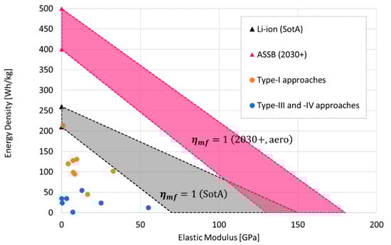
Figure 13.
Specific energy vs. elastic modulus plots of structural batteries, as reported in the literature (complied from data reported in [11,23]) and structural battery targets: SotA (grey area) and for aeronautic applications in 2030+ (pink area).
As a SotA base-line, functionally separated systems are considered, using for their electrical energy storage current commercial, high energy lithium-iron-phosphate (LFP) and lithium-nickel-manganese-cobalt-oxide (NMC) battery cells with a gravimetric energy density of around 160 Wh/kg [101], up to 210 Wh/kg [102] for LFP and 260 Wh/kg [27] for NMC, and, for the structural part, CF fabric and unidirectional (UD) composite materials (60% fiber with resin) with an elastic modulus of between 70 GPa (fabrics) and 150 Gpa (UD) [28,29]. These provide the boundaries for the SotA area (the gray area in Figure 13) within which structural batteries would have a multifunctional efficiency , depending on the respective constituents used.
Although higher mass savings are predicted for high degrees of structural integration, i.e., for type-III and type-IV batteries, available results show that structural batteries with a low degree of multifunctionality, i.e., type I, exhibit better multifunctional performances. Several type-I concepts approach the lower boundary of the target area, showing, in general, higher energy density but having a lower elastic modulus compared to type-III and type-IV concepts that have higher elastic moduli but that have shown rather limited energy density, between 1/10 to 1/3 of the density achievable in conventional battery cells. In fact, current type-I concepts often incorporate liquid electrolyte battery cells in a pouch format, with low load-bearing capabilities, while type-III and type-IV concepts are far from being optimized in their content and the weight of passive components.
Furthermore, Hopkins et al. [23] highlight that decoupled (type I), sandwich-type approaches can achieve higher flexural rigidity values than those for comparable coupled (types III and IV) versions as, in the former, the structural material is concentrated in the face skins.
Projecting the requirements for aeronautic SB application forward to 2030+, the baseline for electrical energy storage will shift, with upcoming battery technologies having substantially higher energy density, such as solid-state batteries with an expected gravimetric energy density of between 400 and 500 Wh/kg at the cell level. Such energy density is required as a minimum for propelling future hybrid-electric regional aircraft (CS-25, 40–50 Pax) and fully electric commuter aircraft (CS-23, 19 Pax), as forecasted per [103], while fully electrical regional aircraft would require energy densities of beyond 500 Wh/kg [104]. For aeronautic structures, composite materials from carbon UD fibers (not woven fabrics) should be considered, with elastic moduli of between about 130 and 180 GPa [29]. This shifts the multifunctional efficiency target farther, as outlined by the pink area in Figure 13. Note that the increase of rigidity in aeronautic structures will not be achieved by further strengthening the composite material (for cost reasons) but instead by optimizing the ply-stacking sequence.
8. Final Recommendations and Conclusions
In order to develop further structural batteries intended for aeronautic application, research efforts have to be undertaken in the fields of materials, integration, testing and monitoring.
On the materials side, the SB cell net energy density needs to be increased by (a) utilizing energy-dense electrochemistry, taking up ongoing developments in battery materials research, specifically in the field of all-solid-state batteries, and transferring them to structural batteries, as well as by (b) optimizing the SB cell with respect to the active material, loading and reducing the content and weight of passive components, such as the current collectors and separator. The intrinsic structural capability of the SB cell needs to be improved by superseding the conventional liquid electrolyte found in many type-I concepts with a performant structural or solid-state electrolyte, with high adhesion between electrolytes and electrodes.
SB integration concepts specifically intended for aeronautic applications need to be developed, considering UD fibers instead of the commonly used 2D-woven fabrics. Aeronautic ply stacking sequences need to be considered and concepts established that optimize the position, shape, and distribution of SB cells within the structure while minimizing the onset of damage. Reliable electrical wiring and connections will need to be integrated into the structure. Thermal management will depend on the final electrochemistry used in the SB. A comprehensive understanding of the influence of SB integration on mechanical properties needs to be developed not only at a material level but at the level of aeronautic structures. SB integration needs to advance from the current materials level to a structural level, i.e., stepping up in the structural testing and certification pyramid [84] from coupons over elements to (sub-)components.
This need calls for advanced characterization and testing methods beyond basic mechanical and electrical tests, to assess the multifunctional performance of aeronautic structural battery composite parts in complex-load cases. These could include multi-instrumented test setups with (high-speed/real-time) digital image correlation, X-ray tomography, acoustic emission tests, and infrared thermography to monitor the damage evolution, especially around the SB cells’ locations.
Furthermore, the state-of-health of the resulting multifunctional structures during manufacturing, testing and operation will need advanced sensing arrays and monitoring with embedded sensors, such as fiber Bragg gratings or piezoelectric sensors, or using novel miniaturized battery-cell-based sensing devices.
Author Contributions
State of the art review, A.B. (Alexander Beutl), F.L., S.W. and M.G.; interaction with industrial experts: F.R.; writing—draft preparation, A.B. (Alexander Beutl), F.M., H.K., F.L., S.W., F.R. and M.G.; writing—review and editing, H.K. and A.B. (Alexander Bismarck); project coordination and funding acquisition, H.K. All authors have read and agreed to the published version of the manuscript.
Funding
This review was prepared within the project SOLIFLY that received funding from the Clean Sky 2 Joint Undertaking (JU) under grant agreement No. 101007577.
Institutional Review Board Statement
Not applicable.
Informed Consent Statement
Not applicable.
Acknowledgments
The authors thank Umberto Mercurio and Guido Saccone at CIRA for their support in interacting with the industrial experts and collecting their inputs.
Conflicts of Interest
The authors declare no conflict of interest.
References
- National Academy of Sciences, Transportation Research Board. Transportation Research Circular E-C271: Critical Issues in Aviation and the Environment 2021; National Academy of Sciences, Transportation Research Board: Washington, DC, USA, 2021. [Google Scholar]
- European Commission. Flightpath 2050—Europe’s Vision for Aviation: Maintaining Global Leadership and Serving Society’s Needs; Publications Office of the European Union: Luxembourg, 2012; ISBN 978-92-79-26229-6. [Google Scholar]
- European Commission. Clean Sky Benefits. Available online: https://www.cleansky.eu/benefits (accessed on 15 September 2021).
- NASA. NASA Aeronautics—Strategic Implementation Plan—2019 Update; NASA: Washington, DC, USA, 2019.
- European Commission. Communication from the Commission—The European Green Deal. Available online: https://eur-lex.europa.eu/legal-content/EN/TXT/?uri=COM%3A2019%3A640%3AFIN (accessed on 15 September 2021).
- UBER Elevate. Fast-Forwarding to a Future of On-Demand Urban Air Transportation. Available online: https://evtol.news/__media/PDFs/UberElevateWhitePaperOct2016.pdf (accessed on 25 September 2021).
- Adam, T.J.; Liao, G.; Petersen, J.; Geier, S.; Finke, B.; Wierach, P.; Kwade, A.; Wiedemann, M. Multifunctional Composites for Future Energy Storage in Aerospace Structures. Energies 2018, 11, 335. [Google Scholar] [CrossRef] [Green Version]
- Scholz, A.E.; Hermanutz, A.; Hornung, M. Feasibility Analysis and Comparative Assessment of Structural Power Technology in All-Electric Composite Aircraft. In Proceedings of the Deutscher Luft- und Raumfahrtkongress 2018, Friedrichshafen, Germany, 4–6 September 2018. [Google Scholar] [CrossRef]
- Snyder, J.F.; O’Brien, D.J.; Wetzel, E.D. Structural Batteries, Capacitors and Supercapacitors. In Handbook of Solid State Batteries, 2nd ed.; Materials and Energy; World Scientific: Singapore, 2015; Volume 6, pp. 657–699. ISBN 978-981-4651-89-9. [Google Scholar]
- Snyder, J.; Gienger, E.; Wetzel, E. Performance Metrics for Structural Composites with Electrochemical Multifunctionality. J. Compos. Mater. 2015, 49, 1835–1848. [Google Scholar] [CrossRef]
- Asp, L.E.; Bouton, K.; Carlstedt, D.; Duan, S.; Harnden, R.; Johannisson, W.; Johansen, M.; Johansson, M.K.G.; Lindbergh, G.; Liu, F.; et al. A Structural Battery and Its Multifunctional Performance. Adv. Energy Sustain. Res. 2021, 2, 2000093. [Google Scholar] [CrossRef]
- Moyer, K.; Boucherbil, N.A.; Zohair, M.; Eaves-Rathert, J.; Pint, C.L. Polymer Reinforced Carbon Fiber Interfaces for High Energy Density Structural Lithium-Ion Batteries. Sustain. Energy Fuels 2020, 4, 2661–2668. [Google Scholar] [CrossRef]
- Thakur, A.; Dong, X. Printing with 3D Continuous Carbon Fiber Multifunctional Composites via UV-Assisted Coextrusion Deposition. Manuf. Lett. 2020, 24, 1–5. [Google Scholar] [CrossRef]
- Meng, C.; Muralidharan, N.; Teblum, E.; Moyer, K.E.; Nessim, G.D.; Pint, C.L. Multifunctional Structural Ultrabattery Composite. Nano Lett. 2018, 18, 7761–7768. [Google Scholar] [CrossRef] [PubMed]
- Liu, P.; Sherman, E.; Jacobsen, A. Design and Fabrication of Multifunctional Structural Batteries. J. Power Sources 2009, 189, 646–650. [Google Scholar] [CrossRef]
- Zhao, Y.; Zhao, D.; Zhang, T.; Li, H.; Zhang, B.; Zhenchong, Z. Preparation and Multifunctional Performance of Carbon Fiber-Reinforced Plastic Composites for Laminated Structural Batteries. Polym. Compos. 2020, 41, 3023–3033. [Google Scholar] [CrossRef]
- Roberts, S.C.; Aglietti, G.S. Structural Performance of a Multifunctional Spacecraft Structure Based on Plastic Lithium-Ion Batteries. Acta Astronaut. 2010, 67, 424–439. [Google Scholar] [CrossRef] [Green Version]
- Thomas, J.; Qidwai, S.; Pogue, W.; Pham, G. Multifunctional Structure-Battery Composites for Marine Systems. J. Compos. Mater. 2013, 47, 5–26. [Google Scholar] [CrossRef]
- Huang, W.; Wang, P.; Liao, X.; Chen, Y.; Borovilas, J.; Jin, T.; Li, A.; Cheng, Q.; Zhang, Y.; Zhai, H.; et al. Mechanically-Robust Structural Lithium-Sulfur Battery with High Energy Density. Energy Storage Mater. 2020, 33, 416–422. [Google Scholar] [CrossRef]
- Moyer, K.; Meng, C.; Marshall, B.; Assal, O.; Eaves, J.; Perez, D.; Karkkainen, R.; Roberson, L.; Pint, C.L. Carbon Fiber Reinforced Structural Lithium-Ion Battery Composite: Multifunctional Power Integration for CubeSats. Energy Storage Mater. 2020, 24, 676–681. [Google Scholar] [CrossRef]
- Attar, P.; Galos, J.; Best, A.S.; Mouritz, A.P. Compression Properties of Multifunctional Composite Structures with Embedded Lithium-Ion Polymer Batteries. Compos. Struct. 2020, 237, 111937. [Google Scholar] [CrossRef]
- Carlstedt, D.; Johannisson, W.; Zenkert, D.; Linde, P.; Asp, L.E. Conceptual Design Framework for Laminated Structural Battery Composites. In Proceedings of the ECCM 2018—18th European Conference on Composite Materials, Athens, Greece, 24 June 2018; pp. 1–8. [Google Scholar]
- Hopkins, B.J.; Long, J.W.; Rolison, D.R.; Parker, J.F. High-Performance Structural Batteries. Joule 2020, 4, 2240–2243. [Google Scholar] [CrossRef]
- Asp, L.E.; Johansson, M.; Lindbergh, G.; Xu, J.; Zenkert, D. Structural Battery Composites: A Review. Funct. Compos. Struct. 2019, 1, 042001. [Google Scholar] [CrossRef]
- Danzi, F.; Salgado, R.M.; Oliveira, J.E.; Arteiro, A.; Camanho, P.P.; Braga, M.H. Structural Batteries: A Review. Molecules 2021, 26, 2203. [Google Scholar] [CrossRef] [PubMed]
- Kalnaus, S.; Asp, L.E.; Li, J.; Veith, G.M.; Nanda, J.; Daniel, C.; Chen, X.C.; Westover, A.; Dudney, N.J. Multifunctional Approaches for Safe Structural Batteries. J. Energy Storage 2021, 40, 102747. [Google Scholar] [CrossRef]
- Armand, M.; Axmann, P.; Bresser, D.; Copley, M.; Edström, K.; Ekberg, C.; Guyomard, D.; Lestriez, B.; Novák, P.; Petranikova, M.; et al. Lithium-Ion Batteries—Current State of the Art and Anticipated Developments. J. Power Sources 2020, 479, 228708. [Google Scholar] [CrossRef]
- Hexcel Corporation. HexPly® Prepreg Technology. Available online: https://www.hexcel.com/user_area/content_media/raw/Prepreg_Technology.pdf (accessed on 15 September 2021).
- Toray Carbon Fibers Europe. Carbon Fibers and Composite Materials Datasheets. Available online: https://toray-cfe.com/en/e-documents/ (accessed on 15 September 2011).
- Thomas, J.P.; Keennon, M.T.; DuPasquier, A.; Qidwai, M.A.; Matic, P. Multifunctional Structure-Battery Materials for Enhanced Performance in Small Unmanned Air Vehicles. In Proceedings of the ASME 2003 International Mechanical Engineering Congress and Exposition, Washington, DC, USA, 15–21 November 2003; pp. 289–292. [Google Scholar]
- Thomas, J.P.; Qidwai, M.A. The Design and Application of Multifunctional Structure-Battery Materials Systems. JOM 2005, 57, 18–24. [Google Scholar] [CrossRef]
- Thomas, J.P.; Qidwai, M.A. Mechanical Design and Performance of Composite Multifunctional Materials. Acta Mater. 2004, 52, 2155–2164. [Google Scholar] [CrossRef]
- Schlichting, A.D.; Eisenbeiser, K. Multifunctional Power Systems for Improved Size, Weight, and Power (SWaP) in Portable Electronic Systems; Technical Report MTR1-5-00-2-9; MITRE: McLean, VA, USA, 2015. [Google Scholar]
- Roberts, S.C.; Aglietti, G.S. Satellite Multi-Functional Power Structure: Feasibility and Mass Savings. Proc. Inst. Mech. Eng. Part G J. Aerosp. Eng. 2008, 222, 41–51. [Google Scholar] [CrossRef] [Green Version]
- Wang, Y.; Peng, C.; Zhang, W. Thermal Analysis of Multifunctional Structural Battery for Satellite Applications. Appl. Therm. Eng. 2015, 78, 209–216. [Google Scholar] [CrossRef]
- Grzesik, B.; Liao, G.; Vogt, D.; Froböse, L.; Kwade, A.; Linke, S.; Stoll, E. Integration of Energy Storage Functionalities into Fiber Reinforced Spacecraft Structures. Acta Astronaut. 2020, 166, 172–179. [Google Scholar] [CrossRef]
- Capovilla, G.; Cestino, E.; Reyneri, L.M.; Romeo, G. Modular Multifunctional Composite Structure for CubeSat Applications: Preliminary Design and Structural Analysis. Aerospace 2020, 7, 17. [Google Scholar] [CrossRef] [Green Version]
- Pattarakunnan, K.; Galos, J.; Das, R.; Mouritz, A.P. Tensile Properties of Multifunctional Composites Embedded with Lithium-Ion Polymer Batteries. Compos. Part A Appl. Sci. Manuf. 2020, 136, 105966. [Google Scholar] [CrossRef]
- Ladpli, R.; Nardari, R.; Wang, Y.; Hernandez-Gallegos, P.A.; Rewari, R.; Kuo, H.T.; Kopsaftopoulos, F.; Kepler, K.D.; Lopez, H.A.; Chang, F.-K. Multifunctional Energy Storage Composites for SHM Distributed Sensor Networks. In Proceedings of the Tenth International Workshop on Structural Health Monitoring 2015, Stanford, CA, USA, 1–3 September 2015; p. 938. [Google Scholar]
- Ladpli, P.; Nardari, R.; Kopsaftopoulos, F.; Wang, Y.; Chang, F.-K. Design of Multifunctional Structural Batteries with Health Monitoring Capabilities. In Proceedings of the 8th European Workshop on Structural Health Monitoring (EWSHM 2016), Bilbao, Spain, 5–8 July 2016; p. 416. [Google Scholar]
- Ladpli, P.; Nardari, R.; Rewari, R.; Liu, H.; Slater, M.; Kepler, K.; Wang, Y.; Kopsaftopoulos, F.; Chang, F.-K. Multifunctional Energy Storage Composites: Design, Fabrication, and Experimental Characterization. In Proceedings of the ASME 2016 10th International Conference on Energy Sustainability collocated with the ASME 2016 Power Conference and the ASME 2016 14th International Conference on Fuel Cell Science, Engineering and Technology, Charlotte, CA, USA, 26–30 June 2016. [Google Scholar]
- Ladpli, P.; Nardari, R.; Liu, H.; Slater, M.; Kepler, K.; Wang, Y.; Kopsaftopoulos, F.; Chang, F.-K. Multitfunctional Energy Storage Composites—Electrochemical and Mechanical Cycling Characterization. In Proceedings of the Battery Congress 2016, Troy, MI, USA, 16–18 May 2016; pp. 1–12. [Google Scholar]
- Ladpli, P.; Nardari, R.; Kopsaftopoulos, F.; Chang, F.-K. Multifunctional Energy Storage Composite Structures with Embedded Lithium-Ion Batteries. J. Power Sources 2019, 414, 517–529. [Google Scholar] [CrossRef] [Green Version]
- Mullenax, J.; Browning, P.; Huebsch, W.; Gautam, M.; Sabolsky, E.M. Composite Multifunctional Lithium-Ion Batteries. ECS Trans. 2012, 41, 175. [Google Scholar] [CrossRef] [Green Version]
- Galos, J.; Khatibi, A.A.; Mouritz, A.P. Vibration and Acoustic Properties of Composites with Embedded Lithium-Ion Polymer Batteries. Compos. Struct. 2019, 220, 677–686. [Google Scholar] [CrossRef]
- Galos, J.; Best, A.S.; Mouritz, A.P. Multifunctional Sandwich Composites Containing Embedded Lithium-Ion Polymer Batteries under Bending Loads. Mater. Des. 2020, 185, 108228. [Google Scholar] [CrossRef]
- Shalouf, S.M.; Zhang, J.; Wang, C.H. Effects of Mechanical Deformation on Electric Performance of Rechargeable Batteries Embedded in Load Carrying Composite Structures. Plast. Rubber Compos. 2014, 43, 98–104. [Google Scholar] [CrossRef]
- Waldmann, T.; Scurtu, R.-G.; Richter, K.; Wohlfahrt-Mehrens, M. 18650 vs. 21700 Li-Ion Cells—A Direct Comparison of Electrochemical, Thermal, and Geometrical Properties. J. Power Sources 2020, 472, 228614. [Google Scholar] [CrossRef]
- Marcelli, D.; Summers, J.; Neudecker, B. LiBaCore II: Power Storage in Primary Structure. In Proceedings of the 43rd AIAA/ASME/ASCE/AHS/ASC Structures, Structural Dynamics, and Materials Conference, Denver, CO, USA, 22–25 April 2002; American Institute of Aeronautics and Astronautics: Denver, CO, USA, 2002. [Google Scholar]
- Neudecker, B.J.; Benson, M.H.; Emerson, B.K. Power Fibers: Thin-Film Batteries on Fiber Substrates; ITN Energy Systems Inc.: Littleton, CO, USA, 2003. [Google Scholar]
- Hagberg, J.; Maples, H.A.; Alvim, K.S.P.; Xu, J.; Johannisson, W.; Bismarck, A.; Zenkert, D.; Lindbergh, G. Lithium Iron Phosphate Coated Carbon Fiber Electrodes for Structural Lithium Ion Batteries. Compos. Sci. Technol. 2018, 162, 235–243. [Google Scholar] [CrossRef] [Green Version]
- Park, H.-W.; Jang, M.-S.; Choi, J.-S.; Pyo, J.; Kim, C.-G. Characteristics of Woven Carbon Fabric Current Collector Electrodes for Structural Battery. Compos. Struct. 2021, 256, 112999. [Google Scholar] [CrossRef]
- Hagberg, J.; Leijonmarck, S.; Lindbergh, G. High Precision Coulometry of Commercial PAN-Based Carbon Fibers as Electrodes in Structural Batteries. J. Electrochem. Soc. 2016, 163, A1790. [Google Scholar] [CrossRef]
- Jacques, E.; Hellqvist Kjell, M.; Zenkert, D.; Lindbergh, G.; Behm, M. Expansion of Carbon Fibres Induced by Lithium Intercalation for Structural Electrode Applications. Carbon 2013, 59, 246–254. [Google Scholar] [CrossRef] [Green Version]
- Park, M.Y.; Kim, J.-H.; Kim, D.K.; Kim, C.G. Perspective on Carbon Fiber Woven Fabric Electrodes for Structural Batteries. Fibers Polym. 2018, 19, 599–606. [Google Scholar] [CrossRef]
- Kjell, M.H.; Jacques, E.; Zenkert, D.; Behm, M.; Lindbergh, G. PAN-Based Carbon Fiber Negative Electrodes for Structural Lithium-Ion Batteries. J. Electrochem. Soc. 2011, 158, A1455. [Google Scholar] [CrossRef] [Green Version]
- Zhu, P.; Gastol, D.; Marshall, J.; Sommerville, R.; Goodship, V.; Kendrick, E. A Review of Current Collectors for Lithium-Ion Batteries. J. Power Sources 2021, 485, 229321. [Google Scholar] [CrossRef]
- Snyder, J.F.; Carter, R.H.; Wong, E.L.; Nguyen, P.A.; Xu, K.; Ngo, E.H.; Wetzel, E.D. Multifunctional Structural Composite Batteries. In Proceedings of the Society for the Advancement of Material and Process Engineering (SAMPE) 2006 Fall Technical Conference, Orlando, FL, USA, 27–30 November 2006; Army Research Laboratory: Aberdeen Proving Ground, MD, USA, 2006. [Google Scholar]
- Snyder, J.F.; Carter, R.H.; Wetzel, E.D. Electrochemical and Mechanical Behavior in Mechanically Robust Solid Polymer Electrolytes for Use in Multifunctional Structural Batteries. Chem. Mater. 2007, 19, 3793–3801. [Google Scholar] [CrossRef]
- Snyder, J.F.; Baechle, D.M.; Wetzel, E.D.; Xu, K. Multifunctional Structural Composite Batteries for U.S. Army Applications. In Proceedings of the Army Science Conference (26th), Orlando, FL, USA, 1–4 December 2008; Army Research Laboratory: Aberdeen Proving Ground, MD, USA, 2008. [Google Scholar]
- Snyder, J.F.; Wetzel, E.D.; Watson, C.M. Improving Multifunctional Behavior in Structural Electrolytes through Copolymerization of Structure- and Conductivity-Promoting Monomers. Polymer 2009, 50, 4906–4916. [Google Scholar] [CrossRef]
- Javaid, A.; Ali, M.Z. Multifunctional Structural Lithium Ion Batteries for Electrical Energy Storage Applications. Mater. Res. Express 2018, 5, 055701. [Google Scholar] [CrossRef]
- Carlstedt, D.; Marklund, E.; Asp, L.E. Effects of State of Charge on Elastic Properties of 3D Structural Battery Composites. Compos. Sci. Technol. 2019, 169, 26–33. [Google Scholar] [CrossRef] [Green Version]
- Carlstedt, D.; Asp, L.E. Thermal and Diffusion Induced Stresses in a Structural Battery under Galvanostatic Cycling. Compos. Sci. Technol. 2019, 179, 69–78. [Google Scholar] [CrossRef]
- Xu, J.; Lindbergh, G.; Varna, J. Multiphysics Modeling of Mechanical and Electrochemical Phenomena in Structural Composites for Energy Storage: Single Carbon Fiber Micro-Battery. J. Reinf. Plast. Compos. 2018, 37, 701–715. [Google Scholar] [CrossRef]
- Carlstedt, D.; Asp, L.E. Performance Analysis Framework for Structural Battery Composites in Electric Vehicles. Compos. Part B Eng. 2020, 186, 107822. [Google Scholar] [CrossRef]
- Asp, L.E.; Leijonmarck, S.; Carlson, T.; Lindbergh, G. Realisation of Structural Battery Composite Materials. In Proceedings of the 20th International Conference on Composite Materials, Copenhagen, Sweden, 19–24 July 2015. [Google Scholar]
- Johannisson, W.; Zenkert, D.; Lindbergh, G. Model of a Structural Battery and Its Potential for System Level Mass Savings. Multifunct. Mater. 2019, 2, 035002. [Google Scholar] [CrossRef]
- Chen, J.; Zhou, Y.; Islam, M.S.; Cheng, X.; Brown, S.A.; Han, Z.; Rider, A.N.; Wang, C.H. Carbon Fiber Reinforced Zn–MnO2 Structural Composite Batteries. Compos. Sci. Technol. 2021, 209, 108787. [Google Scholar] [CrossRef]
- Wang, M.; Emre, A.; Tung, S.; Gerber, A.; Wang, D.; Huang, Y.; Cecen, V.; Kotov, N.A. Biomimetic Solid-State Zn2+ Electrolyte for Corrugated Structural Batteries. ACS Nano 2019, 13, 1107–1115. [Google Scholar] [CrossRef]
- Asp, L.E.; Greenhalgh, E.S. Structural Power Composites. Compos. Sci. Technol. 2014, 101, 41–61. [Google Scholar] [CrossRef]
- Asp, L.E. Multifunctional Composite Materials for Energy Storage in Structural Load Paths. Plast. Rubber Compos. 2013, 42, 144–149. [Google Scholar] [CrossRef] [Green Version]
- Greenhalgh, E.S.; Ankersen, J.; Asp, L.E.; Bismarck, A.; Fontana, Q.P.V.; Houlle, M.; Kalinka, G.; Kucernak, A.; Mistry, M.; Nguyen, S.; et al. Mechanical, Electrical and Microstructural Characterisation of Multifunctional Structural Power Composites. J. Compos. Mater. 2015, 49, 1823–1834. [Google Scholar] [CrossRef] [Green Version]
- Jacques, E.; Kjell, M.H.; Zenkert, D.; Lindbergh, G. The Effect of Lithium-Intercalation on the Mechanical Properties of Carbon Fibres. Carbon 2014, 68, 725–733. [Google Scholar] [CrossRef]
- Carlson, T. Multifunctional Composite Materials Design, Manufacture and Experimental Characterisation. Ph.D. Thesis, Luleå University of Technology, Luleå, Sweden, 2013. [Google Scholar]
- Asp, L.E. Structural Battery Materials. In Proceedings of the ECCM15—15th European Conference on Composite Materials, Venice, Italy, 24–28 June 2012; p. 1061. [Google Scholar]
- Jiang, Q.; Zhang, H.; Rusakov, D.; Yousefi, N.; Bismarck, A. Additive Manufactured Carbon Nanotube/Epoxy Nanocomposites for Heavy-Duty Applications. ACS Appl. Polym. Mater. 2021, 3, 93–97. [Google Scholar] [CrossRef] [PubMed]
- Asp, L.E.; Greenhalgh, E.S. Chapter 20: Multifunctional Structural Battery and Supercapacitor Composites. In Multifunctionality of Polymer Composites; William Andrew Publishing: Norwich, NY, USA, 2015. [Google Scholar]
- Volvo Car Group. Volvo Car Group Makes Conventional Batteries a Thing of the Past. Available online: https://www.media.volvocars.com/global/en-gb/media/pressreleases/134235/volvo-car-group-makes-conventional-batteries-a-thing-of-the-past (accessed on 15 September 2021).
- Johannisson, W.; Ihrner, N.; Zenkert, D.; Johansson, M.; Carlstedt, D.; Asp, L.E.; Sieland, F. Multifunctional Performance of a Carbon Fiber UD Lamina Electrode for Structural Batteries. Compos. Sci. Technol. 2018, 168, 81–87. [Google Scholar] [CrossRef]
- ASTM. Standard Test Method for Short-Beam Strength of Polymer Matrix Composite Materials and Their Laminates; ASTM International: West Conshohocken, PA, USA, 2016. [Google Scholar]
- AITM. Airbus Test Method Standard: Determination of Plain, Open Hole and Filled Hole Tensile Strength; Norm AITM 1-0008 Issue 3; AITM: Blagnac, France, 2004; pp. 1–16. [Google Scholar]
- Zhang, Y.; Ma, J.; Singh, A.K.; Cao, L.; Seo, J.; Rahn, C.D.; Bakis, C.E.; Hickner, M.A. Multifunctional Structural Lithium-Ion Battery for Electric Vehicles. J. Intell. Mater. Syst. Struct. 2017, 28, 1603–1613. [Google Scholar] [CrossRef] [Green Version]
- Federal Aviation Administration. AC 20-107B—Composite Aircraft Structure; Federal Aviation Administration: Washington, DC, USA, 2009.
- Federal Aviation Administration. Standard Airworthiness Certification—Regulations. Available online: https://www.faa.gov/aircraft/air_cert/airworthiness_certification/std_awcert/std_awcert_regs/regs/ (accessed on 15 September 2021).
- European Union Aviation Safety Agency. EASA CM-S-010 Composite Materials—The Safe Design and Use of Monocoque Sandwich Structures in Principal Structural Element Application; European Union Aviation Safety Agency: Cologne, Germany, 2018. [Google Scholar]
- U.S. Department of Defense. Military Handbook—MIL-HDBK-17-1F: Composite Materials Handbook, Volume 1—Polymer Matrix Composites Guidelines for Characterization of Structural Materials; U.S. Department of Defense: Washington, DC, USA, 2002.
- Federal Aviation Administration. AC 20-184—Guidance on Testing and Installation of Rechargeable Lithium Battery and Battery Systems on Aircraft; Federal Aviation Administration: Washington, DC, USA, 2015.
- RTCA. DO-311A—Minimum Operational Performance Standards for Rechargeable Lithium Batteries and Battery Systems; RTCA: Washington, DC, USA, 2017. [Google Scholar]
- RTCA. DO-347—Certification Test Guidance for Small and Medium Sized Rechargeable Lithium Batteries and Battery Systems; RTCA: Washington, DC, USA, 2013. [Google Scholar]
- Federal Aviation Administration. TSO-C179b—Rechargeable Lithium Batteries and Battery Systems; Federal Aviation Administration: Washington, DC, USA, 2018.
- Federal Aviation Administration. AC 25.856-1—Thermal/Acoustic Insulation Flame Propagation Test Method Details—Document Information; Federal Aviation Administration: Washington, DC, USA, 2005.
- Federal Aviation Administration. Aircraft Materials Fire Test Handbook, Revision 3; Federal Aviation Administration: Washington, DC, USA, 2019.
- European Union Aviation Safety Agency. Special Condition LSA Propulsion Lithium Batteries SC-LSA-Fx2480; European Union Aviation Safety Agency: Cologne, Germany, 2017. [Google Scholar]
- European Union Aviation Safety Agency. Special Condition SC E-19—Electric/Hybrid Propulsion System—Issue 01; European Union Aviation Safety Agency: Cologne, Germany, 2021. [Google Scholar]
- Rajamani, R.; Mracek Dietrich, A. Unsettled Issues Regarding the Certification of Electric Aircraft; SAE International: Warrendale, PA, USA, 2021; pp. 1–40. [Google Scholar]
- Yang, H. A Review of Structural Batteries Implementations and Applications. In Proceedings of the 2020 IEEE Transportation Electrification Conference & Expo (ITEC), Chicago, IL, USA, 23–25 June 2020; pp. 223–228. [Google Scholar]
- Riboldi, C.E.D.; Trainelli, L.; Biondani, F. Structural Batteries in Aviation: A Preliminary Sizing Methodology. J. Aerosp. Eng. 2020, 33, 04020031. [Google Scholar] [CrossRef]
- Nguyen, S.N.; Millereux, A.; Pouyat, A.; Greenhalgh, E.S.; Shaffer, M.S.P.; Kucernak, A.R.J.; Linde, P. Conceptual Multifunctional Design, Feasibility and Requirements for Structural Power in Aircraft Cabins. J. Aircr. 2021, 58, 677–687. [Google Scholar] [CrossRef]
- Karadotcheva, E.; Nguyen, S.N.; Greenhalgh, E.S.; Shaffer, M.S.P.; Kucernak, A.R.J.; Linde, P. Structural Power Performance Targets for Future Electric Aircraft. Energies 2021, 14, 6006. [Google Scholar] [CrossRef]
- Lithium System AG. Datasheet LFP EP-LFP-277Ah; Lithium System AG: Effretikon, Switzerland, 2021. [Google Scholar]
- Gotion High-Tech. Gotion High-Tech Presents New LFP Pouch Cell with 210 Wh/Kg. Available online: https://www.gotion.com.cn/welcome/newsdetails/486.html (accessed on 15 September 2021).
- European Commission—Batteries Europe ETIP. WG5: Application and Integration: Mobile—Roadmap, Air Transport Chapter; European Commission: Brussels, Belgium, in publication.
- Bills, A.; Sripad, S.; Fredericks, W.L.; Singh, M.; Viswanathan, V. Performance Metrics Required of Next-Generation Batteries to Electrify Commercial Aircraft. ACS Energy Lett. 2020, 5, 663–668. [Google Scholar] [CrossRef] [Green Version]
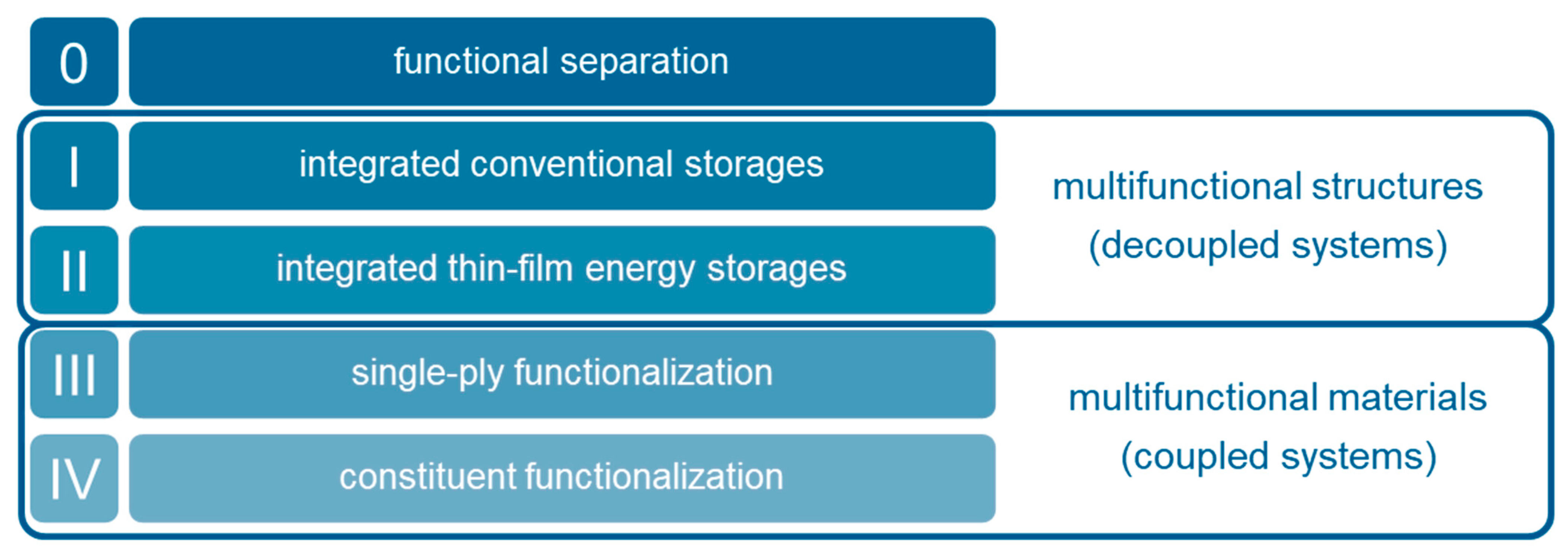

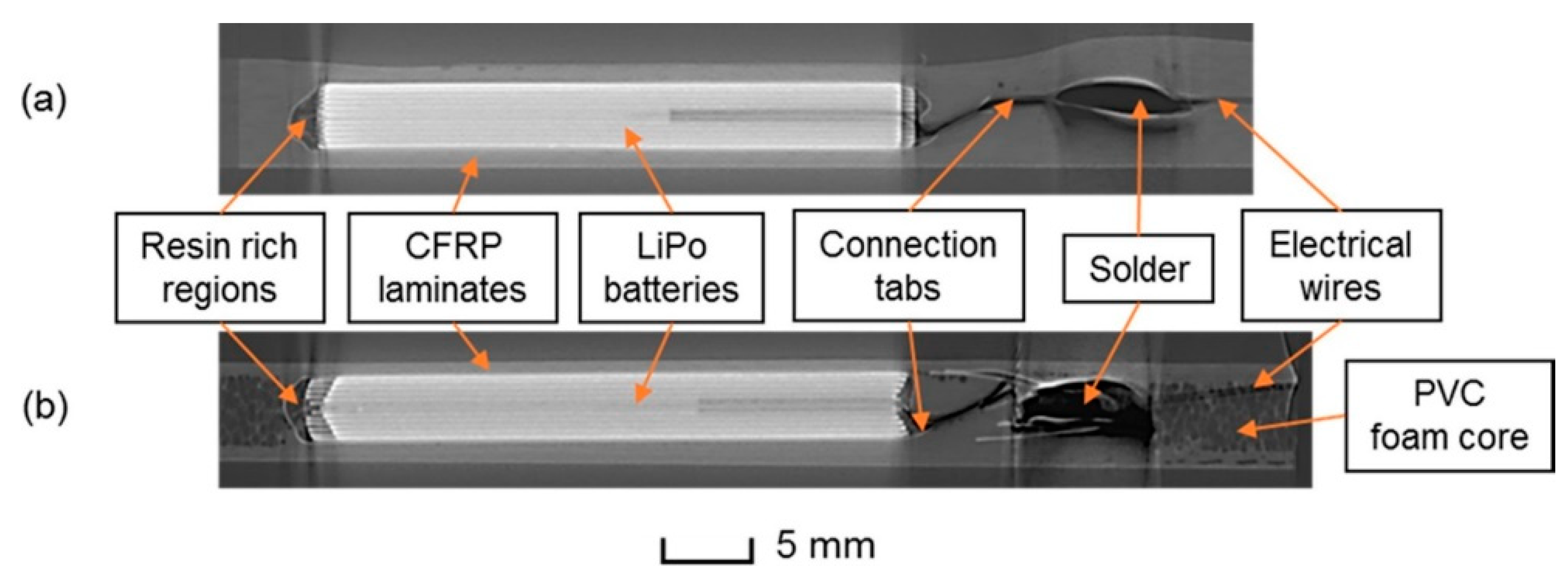
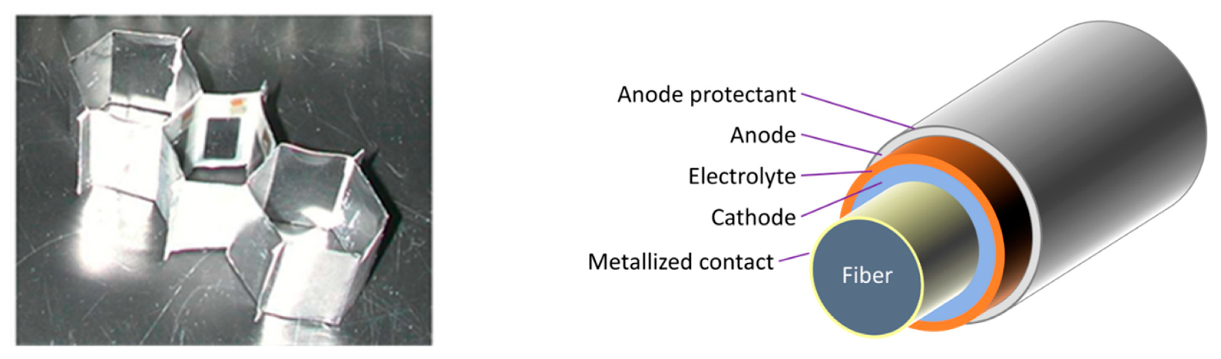

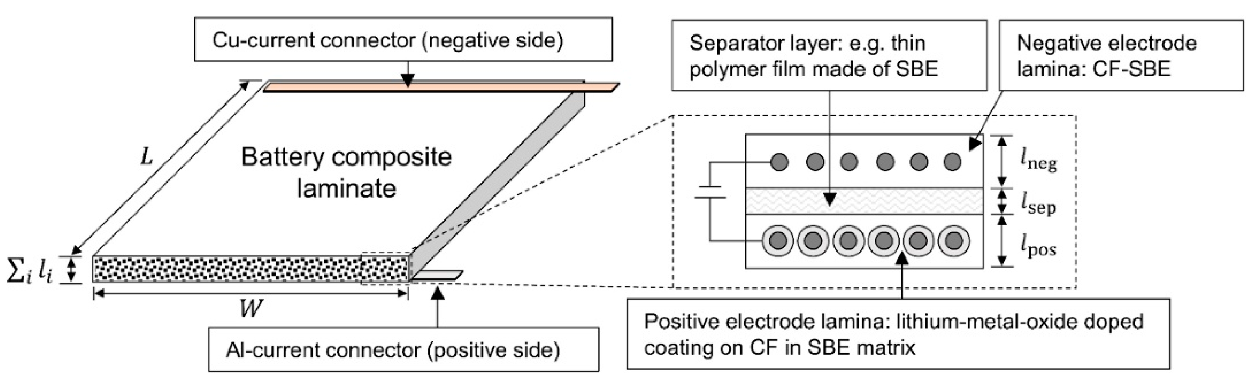
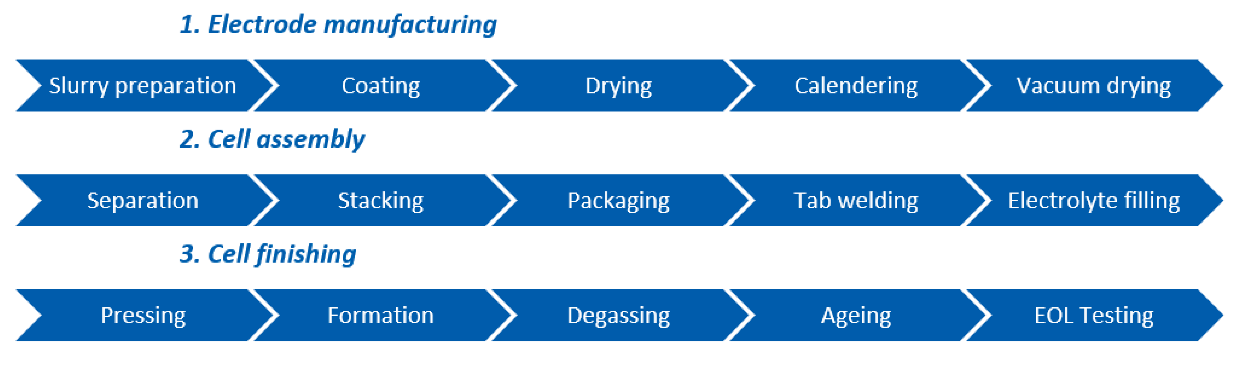
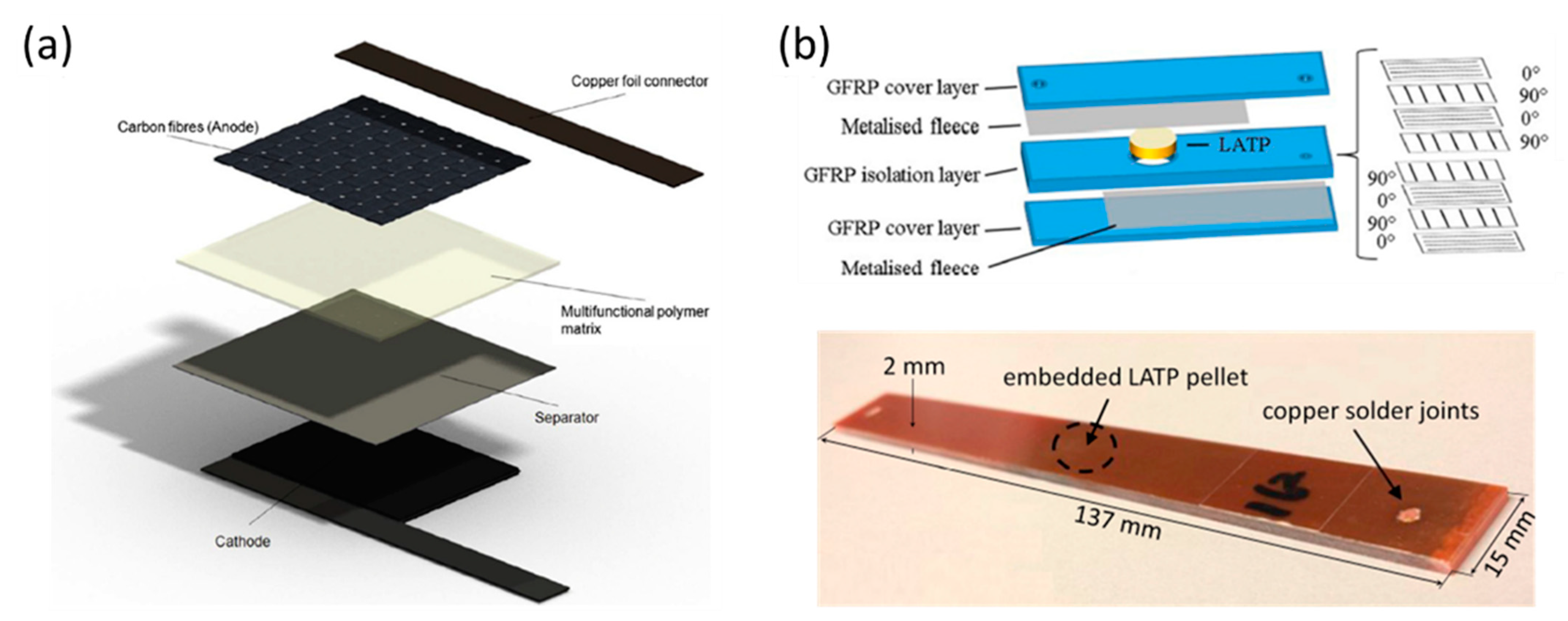

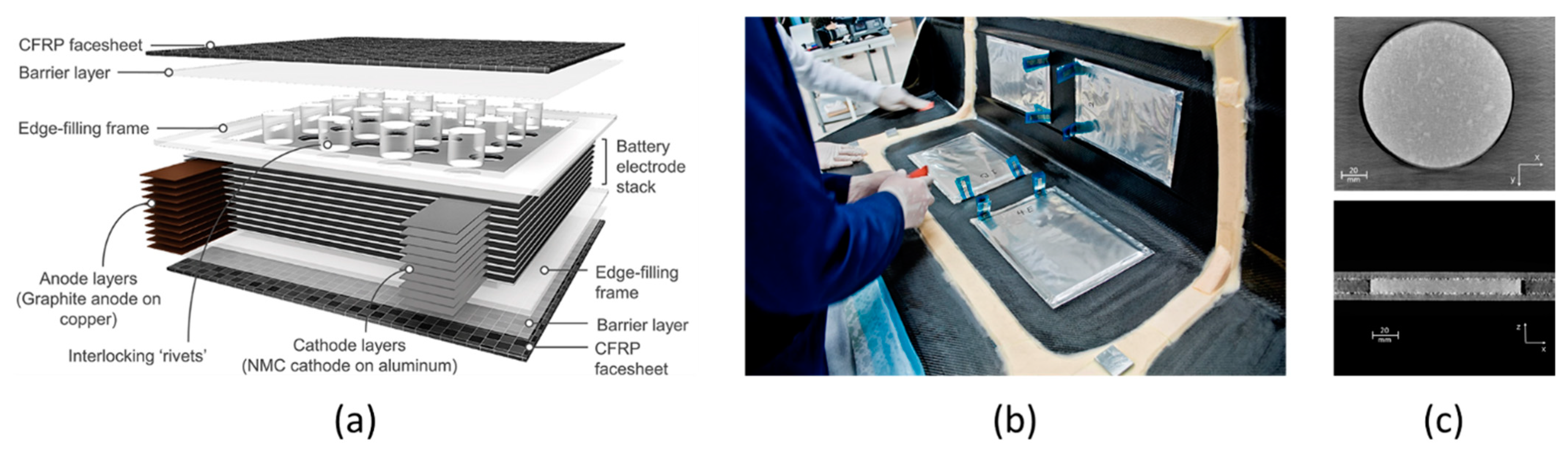
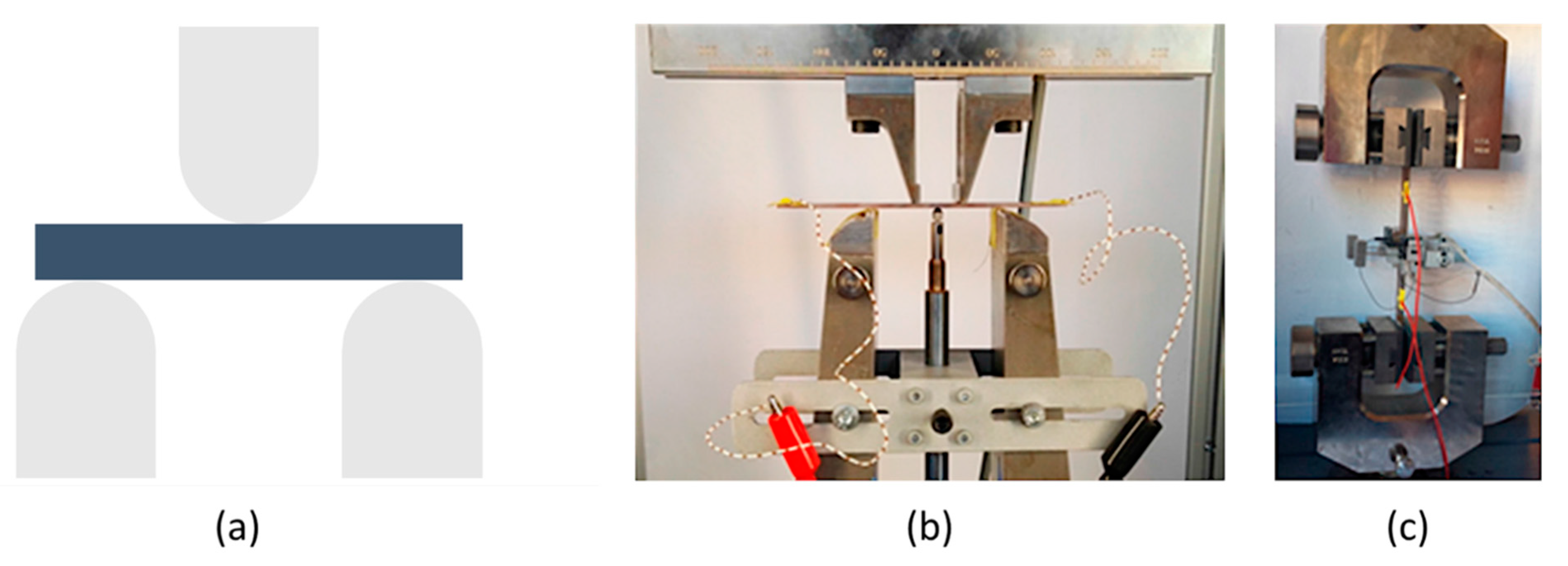
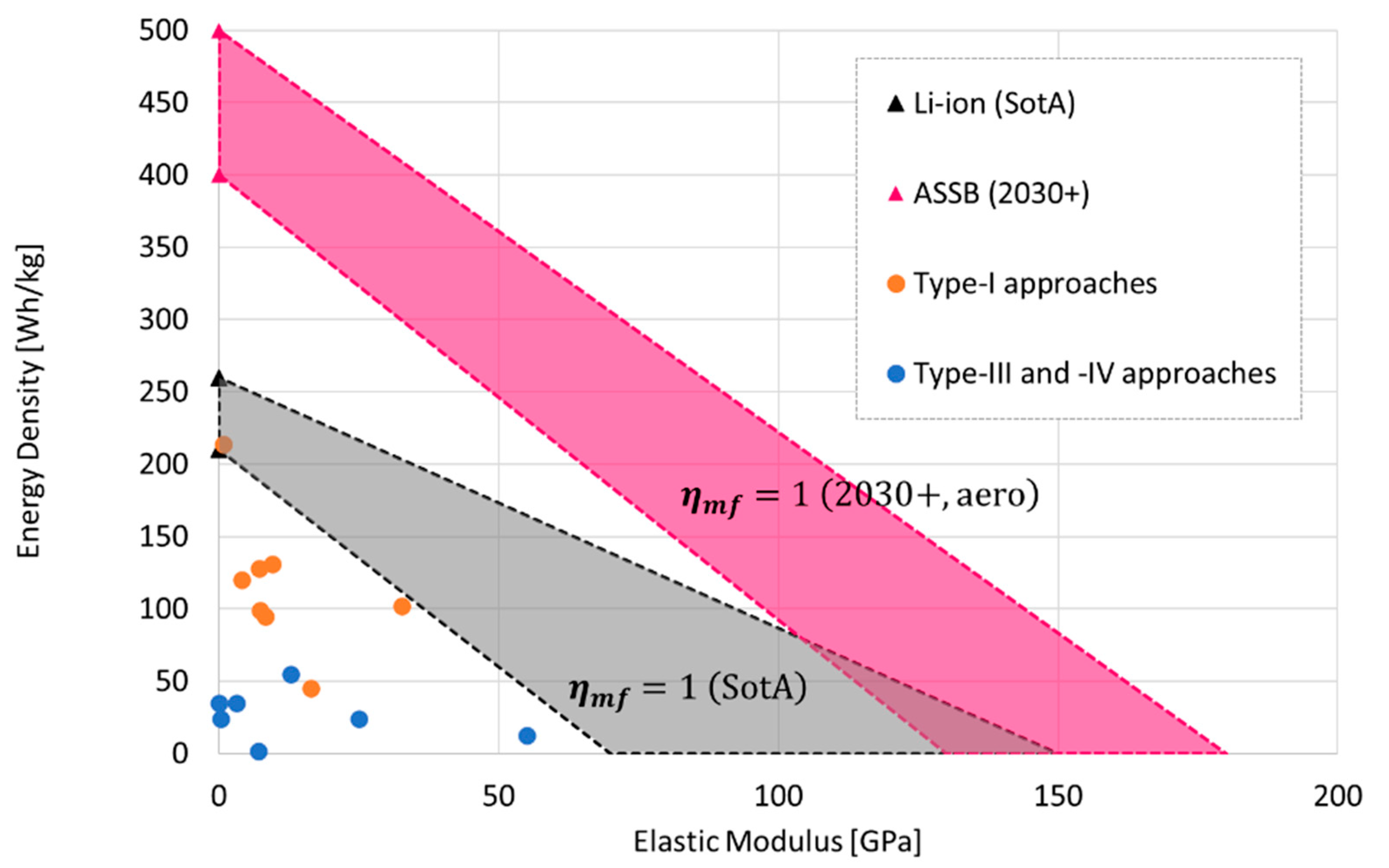
Publisher’s Note: MDPI stays neutral with regard to jurisdictional claims in published maps and institutional affiliations. |
© 2021 by the authors. Licensee MDPI, Basel, Switzerland. This article is an open access article distributed under the terms and conditions of the Creative Commons Attribution (CC BY) license (https://creativecommons.org/licenses/by/4.0/).