Article

Development of On-Board Tilt Mirror Calibration Mechanism without Holding and Release Mechanism

1
Department of Aerospace Engineering, Chosun University, 375 Seosuk-dong, Dong-gu, Gwangju 501-759, Korea
2
Mechatronics Groups, Hanwha Systems, Gyeonggidong-ro, Namsa-myeon, Cheoin-gu, Yongin-si 491-23, Korea
3
Korea Aerospace Research Institute, Gwahak-ro, Yuseong-gu, Daejeon 169-84, Korea
*
Author to whom correspondence should be addressed.
Aerospace 2021, 8(10), 284; https://doi.org/10.3390/aerospace8100284
Submission received: 28 August 2021 / Revised: 20 September 2021 / Accepted: 22 September 2021 / Published: 1 October 2021
(This article belongs to the Special Issue Vibration Control for Space Application)

Abstract

:
The on-board tilting mirror calibration mechanism has a mechanical driving part that helps to achieve the main functional modes of deployment and stow when calibrating a spaceborne imaging sensor. In general, it is necessary to consider a holding and release device in the mechanism design, to secure the structural safety of the mechanical driving part in severe launch environments. However, in the present study, we proposed a novel design strategy based on mass balancing, to guarantee mechanical safety on the driving part of the tilt mirror mechanism, although the implementation of the holding and release mechanism was not considered in the design. The effectiveness of the proposed design was experimentally verified via launch vibration and life cycle tests. The test results demonstrated that the mechanism fulfills all the required functions, and the design approach proposed in this study is effective for ensuring mechanical safety on the driving part of the tilting mirror mechanism in severe launch vibration environments.

1. Introduction

To guarantee the long-term stability of spaceborne infrared (IR) imaging sensors, the sensor’s non-uniform output characteristics should be periodically calibrated using an on-board calibration device during its on-orbit operation [1,2,3,4,5]. The non-uniform characteristics of the sensor arise from the time elapsed, and continuous on and off operation of the sensor in an orbit. Therefore, several types of in-orbit calibration technologies, such as lamps, solar radiation, and blackbody-based calibration, have been developed and implemented in actual space programs [2,3,4,5]. Blackbody-based calibration has been widely utilized to provide a uniform and precisely known radiance temperature to an imaging sensor for on-board calibration [6,7]. Olschewski et al. [6] developed a GLORIA in-flight calibration system comprising two high-precision blackbodies that are independently controlled at cold and hot temperatures using thermo-electric coolers. Oh et al. [7] proposed an on-board blackbody system that can provide a broad range of radiance temperatures achieved by the thermal design of a blackbody using heat pipes, radiators, and heaters.
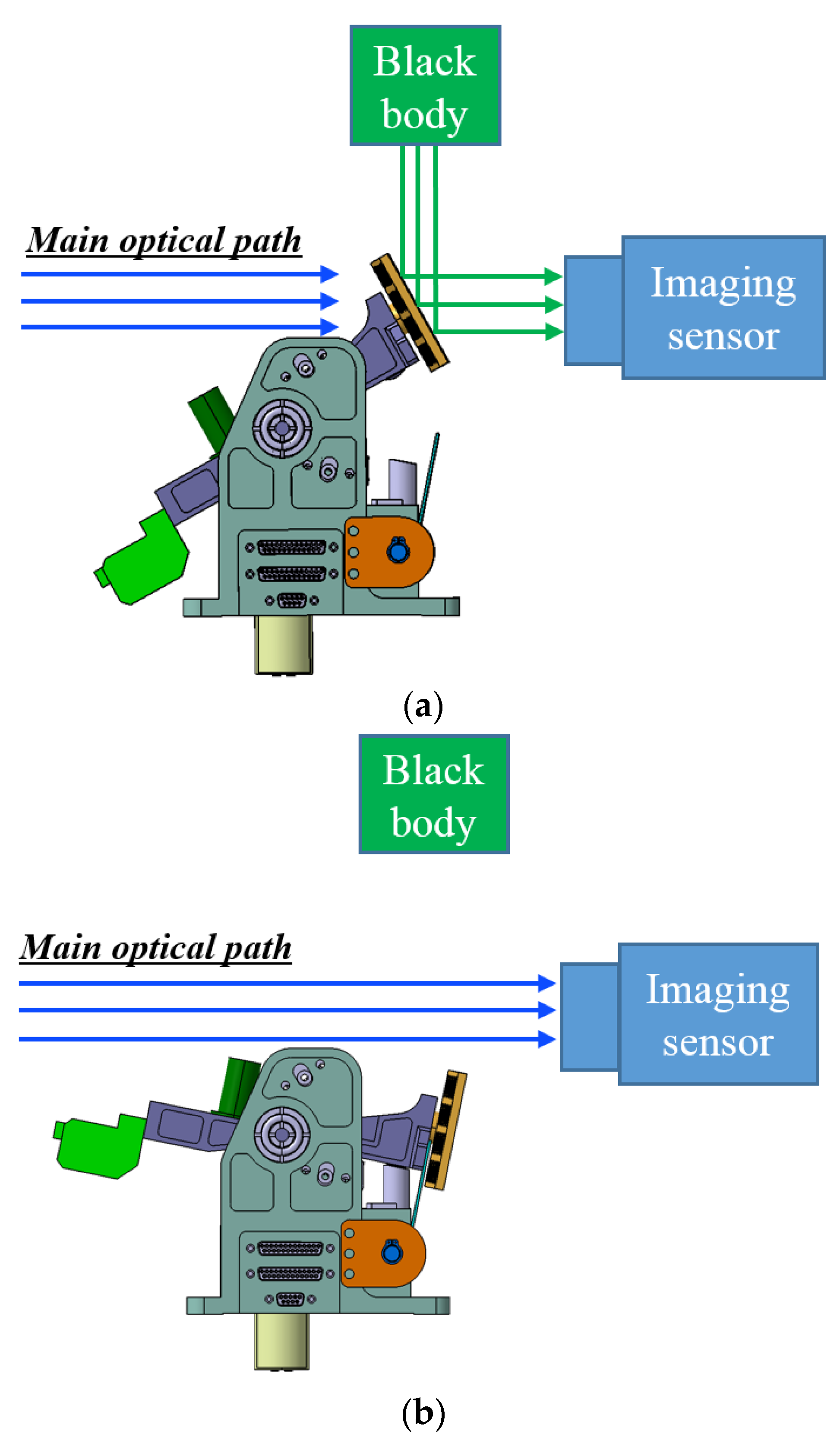
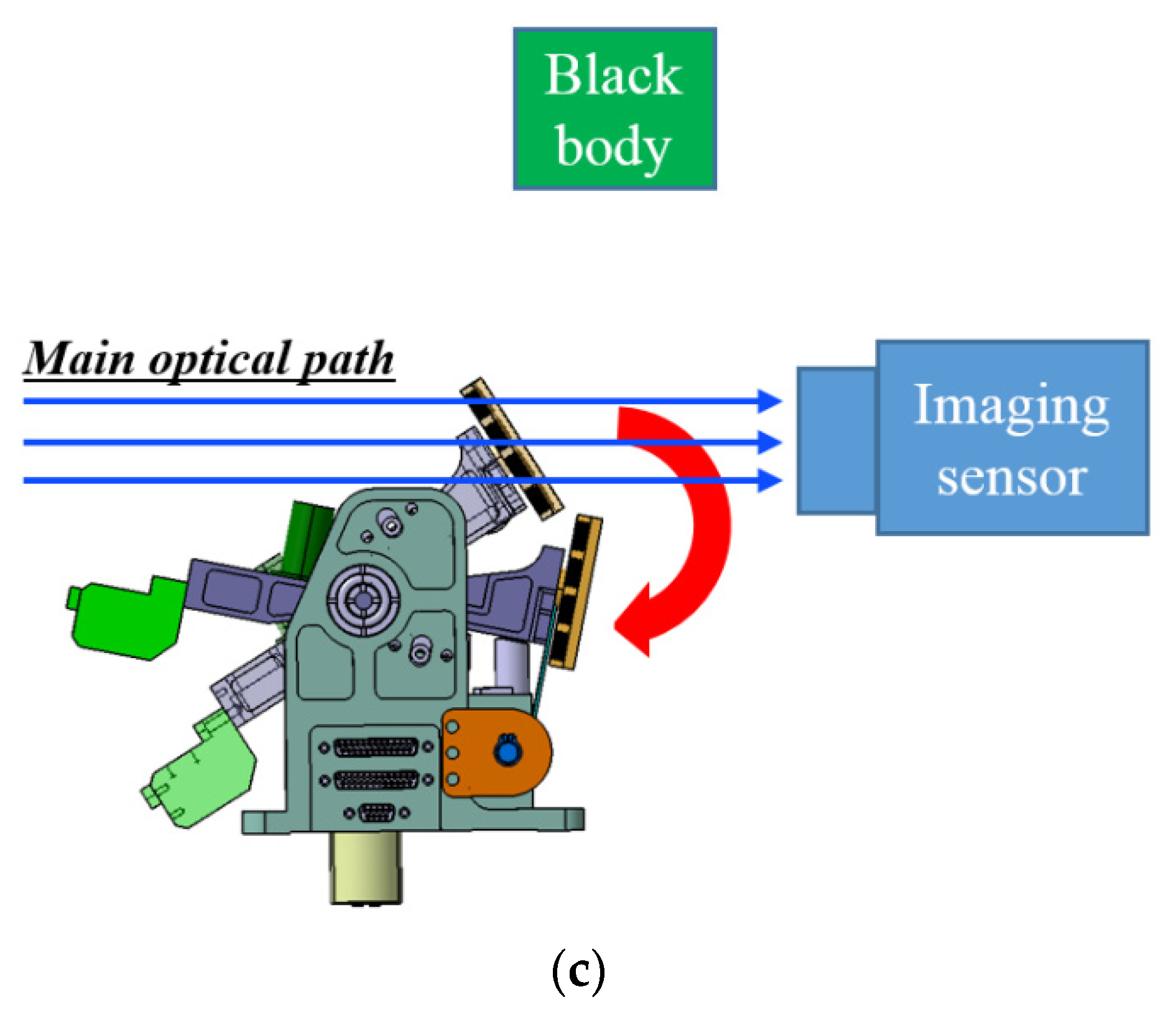
To reflect the referenced radiance temperature from the calibration target of an on-board blackbody to the image sensor, a scanning or tilting calibration mirror mechanism has been widely utilized for space applications [
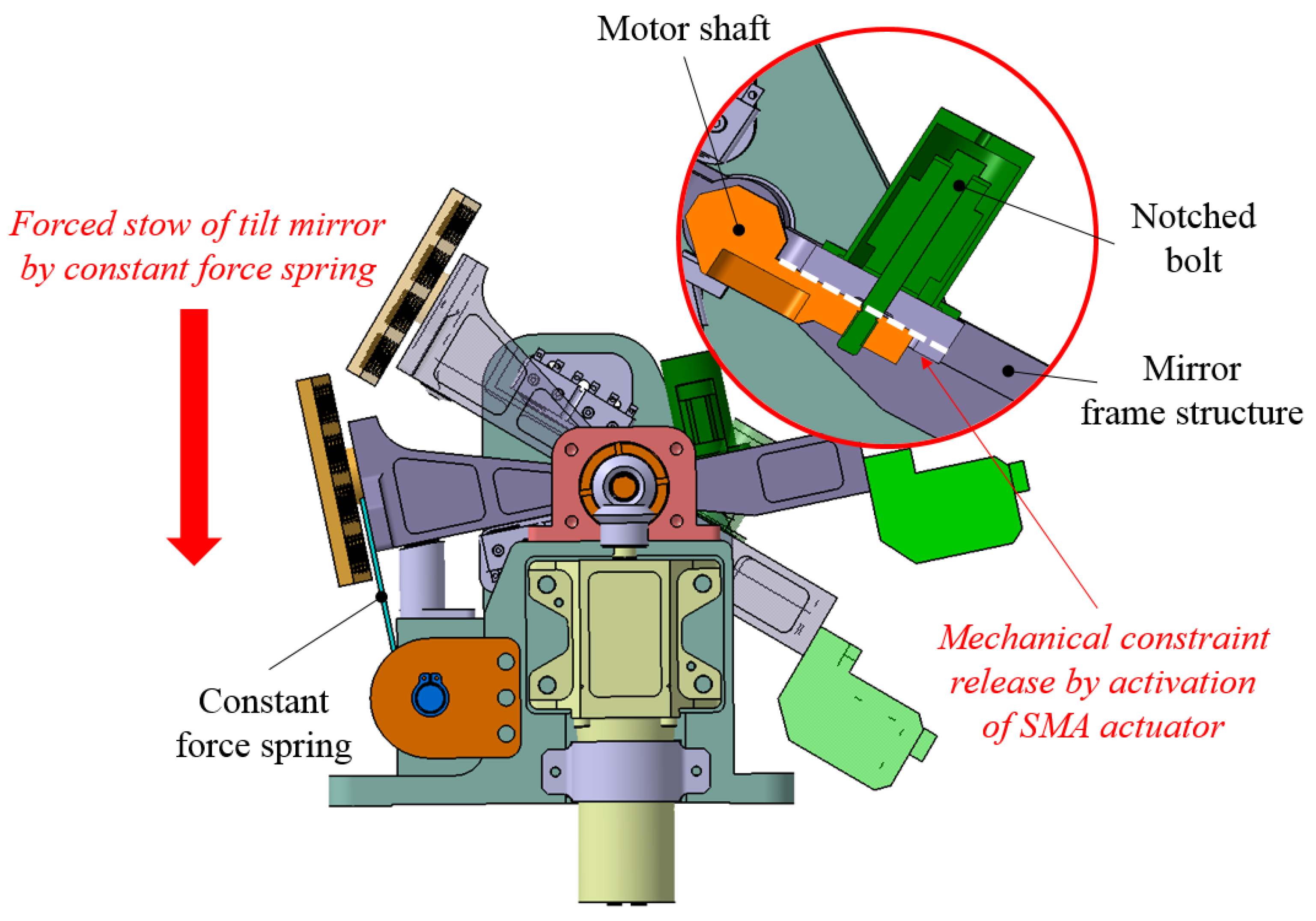
8]. The main function of the mechanism is periodically deployed to view the blackbody during sensor calibration, and is stowed again to avoid interference with the main optical path during image acquisition. Therefore, the structural safety of the mechanical driving part of the mechanism should be ensured by incorporating a holding and release mechanism (HRM) to guarantee its reliable on-orbit operation. This is one of the most frequently utilized design approaches to avoid structural damage to the moving part, by satisfying the stiffness requirement during the launch event. In a previous study, the out-of-plane directional constraint of the tilt mirror mechanism developed by Oh et al. [8] was also implemented by HRM, in combination with a ball-and-socket mechanism to achieve the in-plane directional constraint of the mechanism. The feature of the mechanism was to implement its fail-safe function by using a frangibolt-type shape memory alloy (SMA) actuator to release the mechanical constraint between the mirror and motor shafts to avoid blocking of the main optical path induced by unexpected failure of the geared step motor operation. Suchman et al. [9] also proposed a MIRO calibration mechanism with a fail-safe function achieved using a pin-puller actuator [10]. Schmid et al. [11] proposed a scan mirror mechanism with a launch lock device to clamp the scan mirror when launching. Compostizo et al. [12] proposed a launch locking device developed for a meteosat third generation (MTG) scan mirror, which can rotate around two axes. The locking mechanism is based on a simple four-bar linkage mechanism that is moved by a spindle nut system. The effectiveness of the design was demonstrated via theoretical prediction analysis and locking/unlocking tests. Oh et al. [13] considered an SMA spring actuator to achieve the dual function of the fail-safe function and mechanical constraint on the tilting calibration mechanism, although the HRM was not considered in this design. The effectiveness of the design was successfully validated via launch environment tests such as a sine burst, random vibration, and pyroshock simulating impulse shock tests.
In general, the optical system integrated with the tilt mirror mechanism positioned inside the spacecraft is thermally decoupled by a multi-layer insulator (MLI) support structure. Therefore, once the mechanism is integrated to the spacecraft, it is impossible to perform the calibration test and validate the normal operation of the mechanism after the environment test by activating the mechanism, because it is securely fixed by HRM to guarantee structural safety on its driving part. This indicates that there is no chance to check the functionality of the mechanism before the satellites lift-off, unless the HRM is released. After activation, a rework for fastening the HRM should be implemented. Regarding the HRM introduced in a previous study [8], it should be sent to a provider for refurbishment of the mechanism. Above all, the current configuration where the tilt mirror mechanism is integrated inside the satellite does not allow accessibility to the mechanism before disassembling the satellite. To overcome the limitation above mentioned, Liu et al. [14] proposed a repeatable launch locking/unlocking device (RLLD) for magnetically suspended momentum flywheel using the motor-screw as locking actuator and a carbon-fiber bracket as unlocking mechanism. Zhang et al. [15] also proposed the repeatable locking/unlocking device based on shape memory alloy wire and coil-spring for magnetic bearing reaction wheel. However, these systems should be applied to the additional driving or trigger parts such as the motor and gear box and heating mechanism for working the shape memory alloy. This led to increased system complexity and lower reliability; additionally, the total mass/volume of the system increased as well. Furthermore, it is no longer feasible to execute on-board calibration if the launch locking mechanism fails to successfully remove the launch constraint.
If it is possible to achieve a tilting calibration mechanism that guarantees the mechanical safety of the driving part in a launch vibration environment, although HRM is not utilized, all the limitations described above can be easily addressed. In this study, this strategy was achieved by affecting a mass balancing on the moving part, and actively conjugating the additional force and torque from the constant force spring and detent torque of the geared step motor, to minimize the rotational movement of the driving mirror of the mechanism during the launch phase. This study deals with the effectiveness of the design verified by functional, launch vibration, and life cycle tests for the demonstration model of the mechanism. The test results demonstrate that the on-board tilt mirror calibration mechanism was successfully designed and validated to meet all the required functions of the mechanism.

2. Design Description of Tilt Mirror Calibration Mechanism

2.1. Operation Modes of Tilt Mirror Calibration Mechanism

A tilt mirror calibration mechanism (TMCM) for on-board calibration of the imaging sensor has operation modes such as deploy mode in on-board calibration and stow mode after calibration, which corresponds to the imaging mode of the main optical payload and fail-safe mode in the emergency mode. Figure 1 shows a schematic view of the main operation modes of the TMCM. In the deployment mode of TMCM, which corresponds to the calibration mode, the imaging sensor is periodically calibrated by utilizing the source of the on-board black body’s radiation temperature, reflected from the tilt mirror when the mechanism maintains a deployed configuration to view the black body, as shown in Figure 1a. After completing the sensor calibration, the tilt mirror should be stowed again to avoid interference with the main optical path for the execution of the main mission of image acquisition, as shown in Figure 1b. If the mechanism stops at a specific position on the main optical path during its operation, this causes a critical mission failure because of the interference between the tilt mirror and the main optical path. In this emergency case, it is impossible to perform the main mission of image acquisition anymore. Therefore, the fail-safe mode should be included in the functional modes of TMCM, such that the tilt mirror is automatically stowed by the fail-safe action of the mechanism in the emergency mode, as shown in Figure 1c.

2.2. Mechanical Design of TMCM

Figure 2 shows the mechanical configuration of the TMCM in stowed and deployed positions. This was proposed to realize a structurally reliable calibration mechanism that survived in severe launch vibration environments, even though the mechanical driving part of a deployable mirror is not securely fixed by the holding and release mechanism. The mechanism mainly comprises a driving and a fail-safe module. The driving module mainly comprises a step motor that imposes a tilting action on the mirror during on-board calibration and limit switches, to check the status of the deployed and stowed mirrors. The upper and lower limit switches are located near the motor axis to minimize the operating force and are utilized to verify the status of the mirrors from an on-orbit telemetry. The upper limit switches are also utilized to judge the mode transition of the motor to the holding torque mode, to maintain the deployed position of the mirror during on-board calibration of the imaging sensor.
According to the European Cooperation for Space Standardization [16], the mechanism should consider additional design improvements to eliminate a potentially critical problem if the value of criticality is greater than six, even though the mechanism meets the allocated reliability. The interference of the mirror with the main optical path because of an unexpected problem during the on-orbit operation of the mechanism is regarded as a critical item from the systems point of view. The fail-safe module to eliminate a potentially critical problem mainly comprises a frangibolt-type shape memory alloy (SMA) actuator [8] and a constant force spring. The operating principle of the mechanism in an emergency case when the mirror stops at a specific position on the main optical path during its operation is to release the mechanical constraint between the motor shaft and the mirror frame structure, by actuating the frangibolt-type SMA actuator, as shown in Figure 3. To recover the original shape of the actuator when the SMA actuator is heated to approximately 100 °C, the notched bolt mechanically connecting the motor shaft and the mirror frame structure is broken by the restoration force of the actuator. Subsequently, the released mirror frame is automatically stowed back to its original position by the restoration force of the constant-force springs. This approach is useful for the mechanism driven by the geared step motor in the emergency condition, because its detent torque is too high to re-stow the mirror automatically by using solely the restoration force of the constant-force springs when the input power is cut off from the motor.
The strategy to secure structural safety on the driving part of the mechanism in a launch vibration environment is to minimize the moment of the rotating frame of the mirror, by applying a counter mass corresponding to the mass of the mirror. In addition, the design actively conjugates the additional force and torque from the constant force spring and detent torque of the step motor to implement a holding force on the rotational mirror frame, instead of applying HRM.
For the design of the TMCM, we derived the torque budget using the ECSS standard rule [17]. The required torque budget for the step motor should be larger than or equal to the total of the external torque from the limit switches, ball bearings, and constant force springs with some margin, as follows:
T m 2 ( 1.1 T g + 1.2 T l + 1.2 T c + 3 T b ) + 1.25 T a c c ,
where T m   is the required torque of the step motor, T g is the gravity torque, T l is the limit switch torque, T c is the constant-force spring torque, T b is the ball bearing friction torque, and T a c c is the acceleration torque. To check the status of successful release for the fail-safe mode, the constant-force spring torque of T c   should be larger than
T c 2 ( T l + T b ) .
Table 1 summarizes the torque budget of the tilting calibration mechanism, and the specifications of the hardware utilized for the mechanism.

3. Structural Analysis of TMCM

To evaluate the effectiveness of the structural design of the TMCM, structural analysis was performed using the 2019 Hypermesh/Optistruct software. Although mass balancing was applied to the TMCM proposed in this study, it is impossible to perfectly coincide the rotational axis of the mechanical driving part with the C.G of the TMCM, owing to the inevitable machining and manufacturing tolerance [
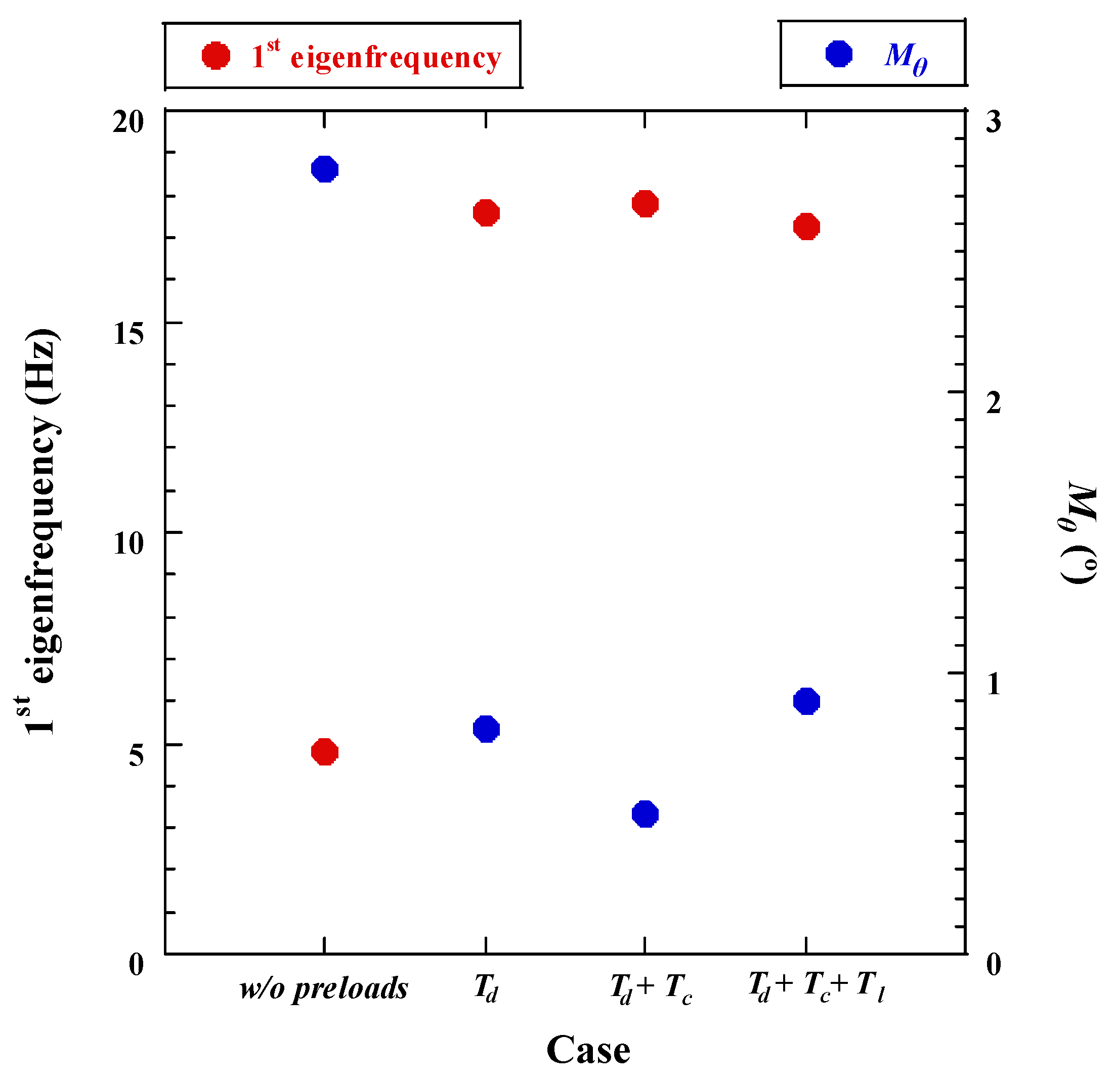
18]. Even a slight imbalance could result in an excessive rotational movement of the mechanical driving part caused by the centrifugal force under launch vibration excitation. Therefore, we performed structural analyses of the TMCM under the condition that the C.G of the TMCM was shifted 1.2 mm from the rational axis as the worst condition, considering the capability of the balancing machine. In addition, the effectiveness of the aforementioned pre-loads in minimizing the rotational movement of the rotational mirror was evaluated in the analysis.
Figure 4 shows the calculated 1st eigenfrequency of the mechanism and the rotational angle ( M θ ) of the tilt mirror under various preload conditions induced by T d , T c , and T l . Here, T d is the detent torque of the step motor and the parameter values adopted in the simulation are listed in Table 1. The value of M θ was calculated when a design load of 50 g was applied along the x-axis, which is the most critical axis in terms of the rotational movement of the mechanism. The 1st eigenfrequency value for the rigid rotational mode of the mechanism without any pre-loads is 4.8 Hz and M θ is 2.8°. This is a condition where only rotational gear stiffness and T b were applied. However, if T d is added to the mechanism, the frequency increases to 17.6 Hz and M θ is 0.8°. In addition, the frequency value is increased to 17.8 Hz, and M θ is decreased to 0.5° when T c is considered. These results indicate that T d is the main parameter that increases the eigenfrequency of the mechanism, and ensures the structural safety of the driving part of the mirror frame by minimizing the angle of M θ . However, the value of T d cannot be increased excessively because the tilt mirror is not automatically stowed by a fail-safe action in emergency cases. The final configuration of the mechanism, considering T l torque in the opposite direction is also plotted in the figure, and the variation in the characteristics of the mechanism is negligible. The modal analysis results of the mechanism under all pre-load conditions are summarized in 
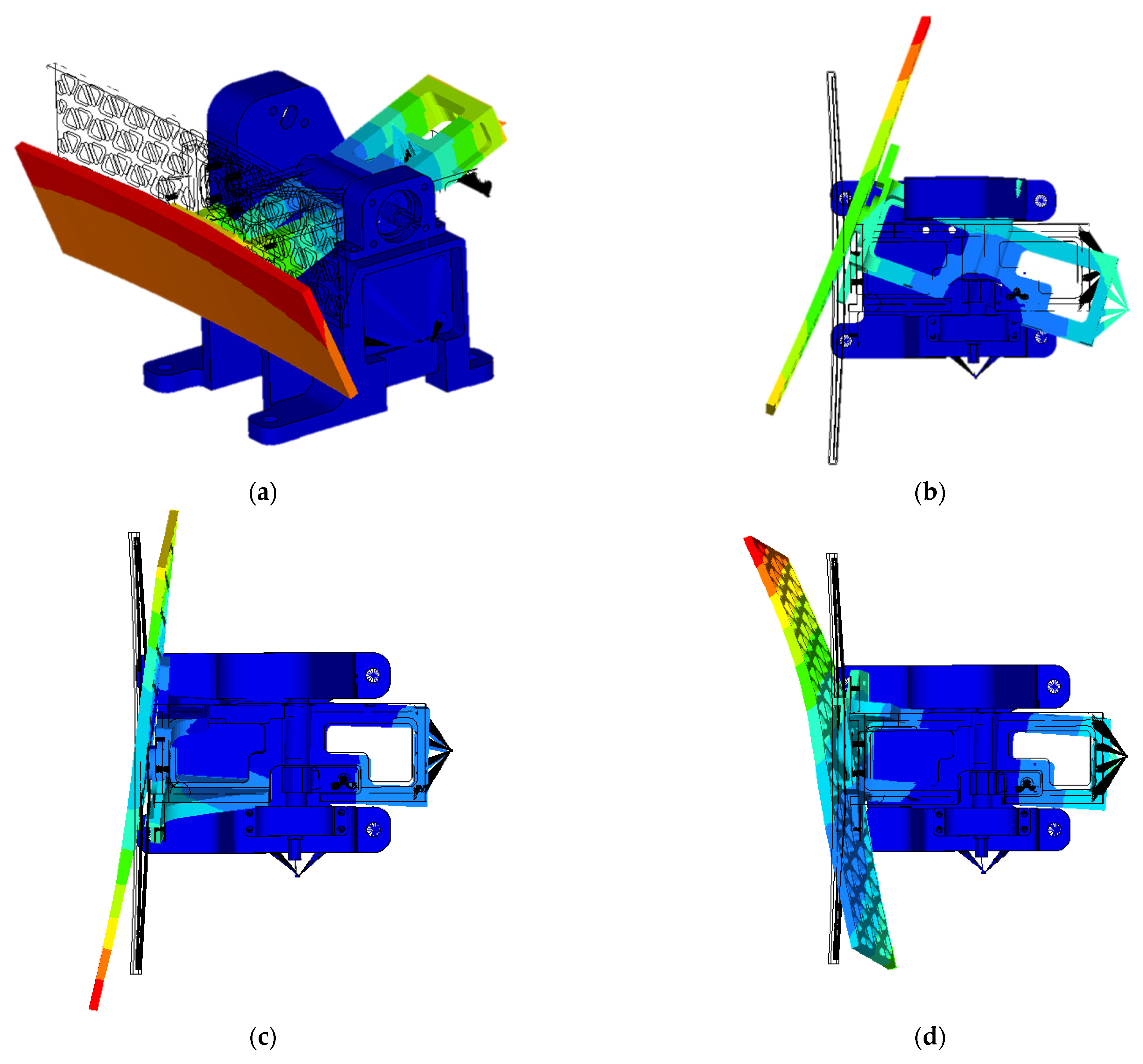
Figure 5. The results of the first mode have been aforementioned, and the torsion mode of the mirror frame for the y-axis was indicated in the second mode at 92.4 Hz. The third and fourth modes at 158.7 and 241.7 Hz, respectively, mainly represent the elastic mode of the mirror frame. These results were utilized to investigate the launch-vibration test results.

4. Experimental Validation of Test Results

To confirm the effectiveness of the proposed TMCM design, we performed an operational function test to validate the deployment and stow functions of the mechanism. The results of the test, obtained prior to launch environment tests to guarantee the structural safety of the TMCM, and life cycle test to ensure on-orbit lifetime of the mechanism, were compared with those conducted after completion of the validation tests.
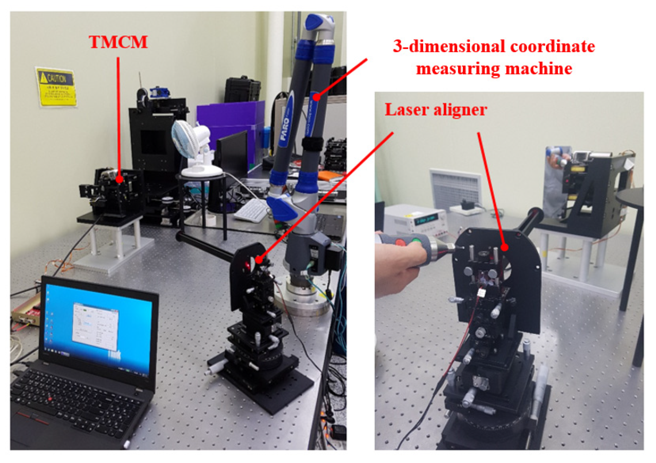
Figure 6 shows the function test setup for TMCM. The TMCM was installed vertically to minimize the effect of the gravitational force during mirror deployment. A 3-dimensional coordinate measuring machine and laser aligner were used to measure the angle between the stowed and deployed positions of the mirror. The required angle for judging the successful deployment of the mirror, measured from its stowed position, was 47.4° ± 0.35°. The function tests were repeated 10 times at a temperature of 20 °C in an ambient environment, to ensure the functionality of the mechanism after the environment test campaign. In this study, a fail-safe function test was not performed because this function has already been validated in a previous study [8] on a tilt mirror unit with a same frangibolt-type SMA actuator utilized in this study.
To verify the structural safety of the proposed TMCM under a severe launch vibration environment, random, sine vibration, and shock tests were performed at the qualification level. Low-level sine sweep (LLSS) tests were performed before and after each vibration test to check the variations in the dynamic characteristics of the mechanism. The criterion for the LLSS test is that the variation in the 1st eigenfrequency is less than 5%. 
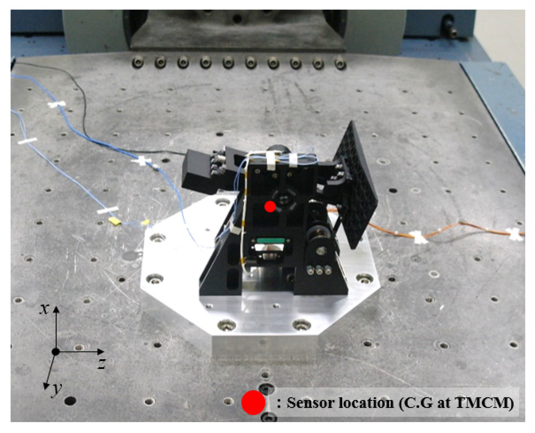
Figure 7 shows an example of launch environment test setups for the TMCM. An accelerometer sensor was mounted on the test fixture to monitor input test loads. The output response of the mechanism was measured at the support frame of the closest position, with respect to the center of gravity of the mechanism. The qualification level test specifications are summarized in Table 2a–c. In the test, notched input profiles were applied to the mechanism to prevent the risk of exceeding the mechanism’s design load of 50 g.
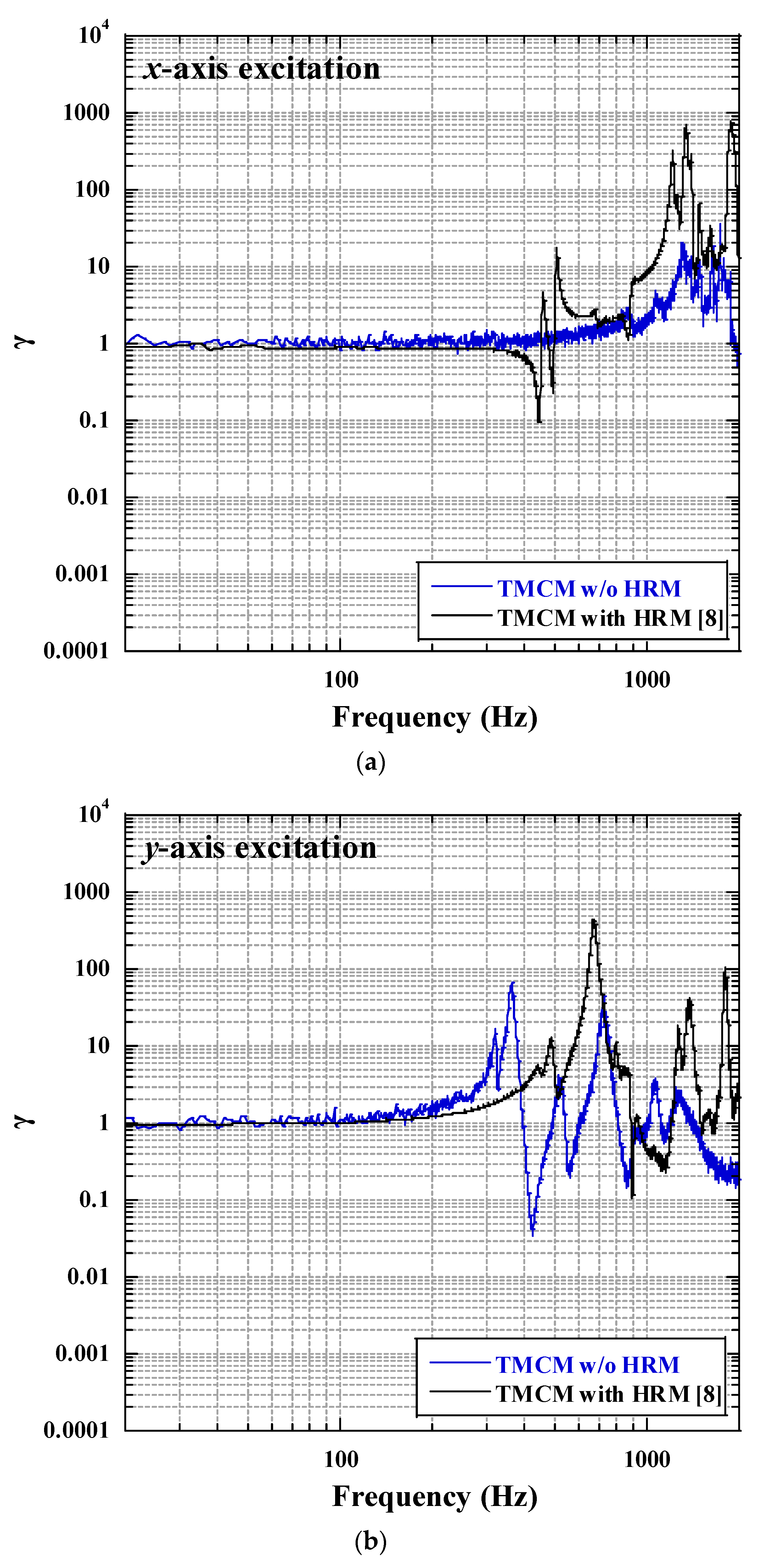
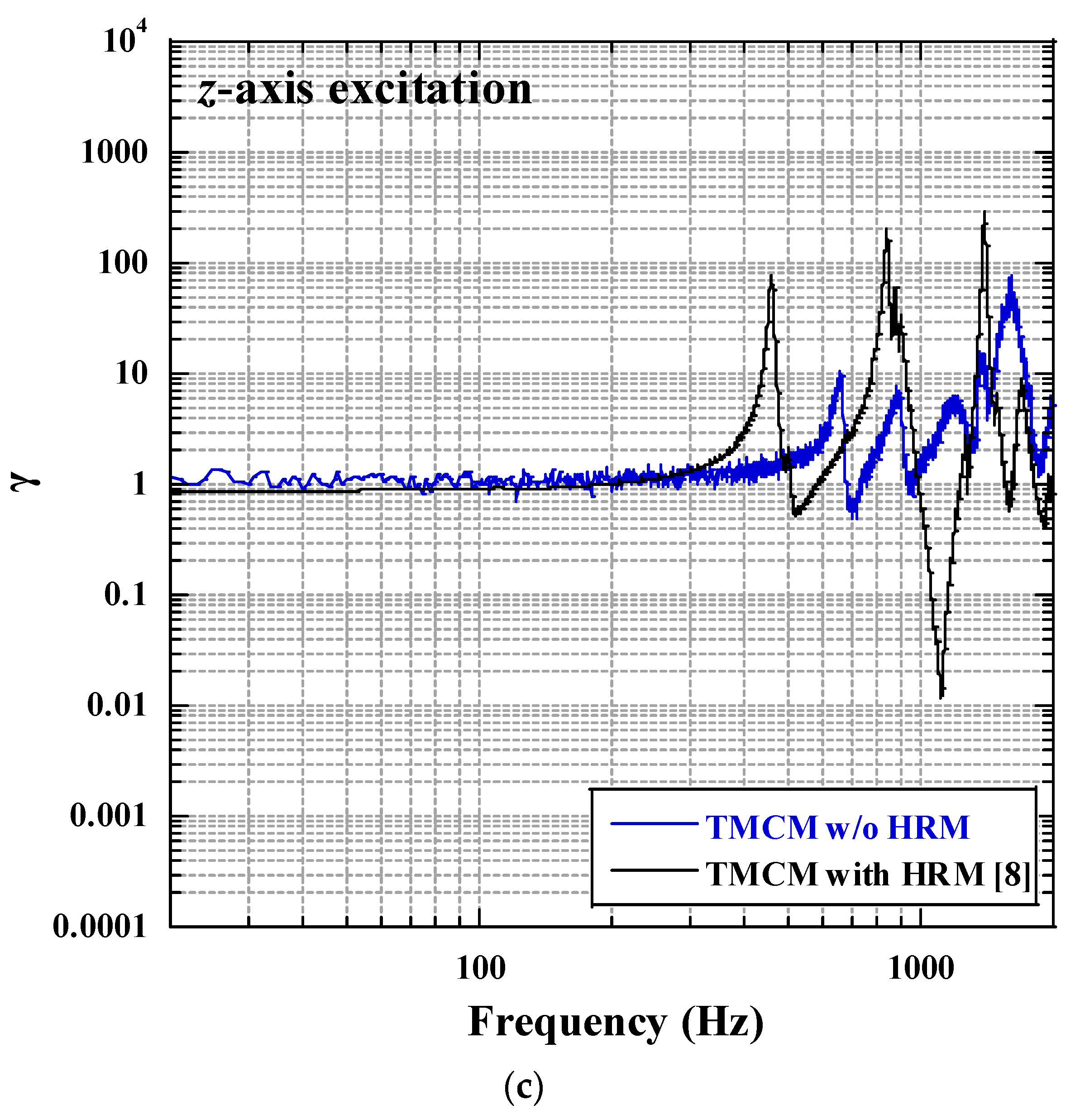
Figure 8a–c show the normalized ratio ( γ ) of the output response to the input test load for each axis of the TMCM, which were calculated from the random test results. To compare the effectiveness of the proposed TMCM with the mass balancing strategy, the results of the conventional TMCM with HRM presented in ref. [8] are also plotted in the figures. The proposed TMCM in this study uses the same step motor model as ref. [8]. The total mass of the proposed TMCM is 3.4 kg, which is 2.4 kg less than that of the previous. Although the mechanical moving part of the proposed TMCM is not constrained by HRM, it exhibits response trends similar to those of the mechanism applying HRM. The responses of the proposed mechanism follow the test inputs until approximately 200 Hz or more, and peaks are observed in the higher frequency range, owing to the elastic modes of the mechanism. Here, the amplitudes of the peaks for the proposed mechanism are relatively lower than those of the conventional mechanism. This is because the friction between the bearing part and rotational shaft results from the rotational movement of the proposed mechanism, in contrast to the conventional mechanism. These test results indicate that the mass balancing strategy of the proposed TMCM indicates a similar or better performance in terms of structural safety, compared with the conventional TMCM with HRM in a launch vibration environment. Based on these results, the structural safety of the proposed TMCM for each launch vibration condition was evaluated.
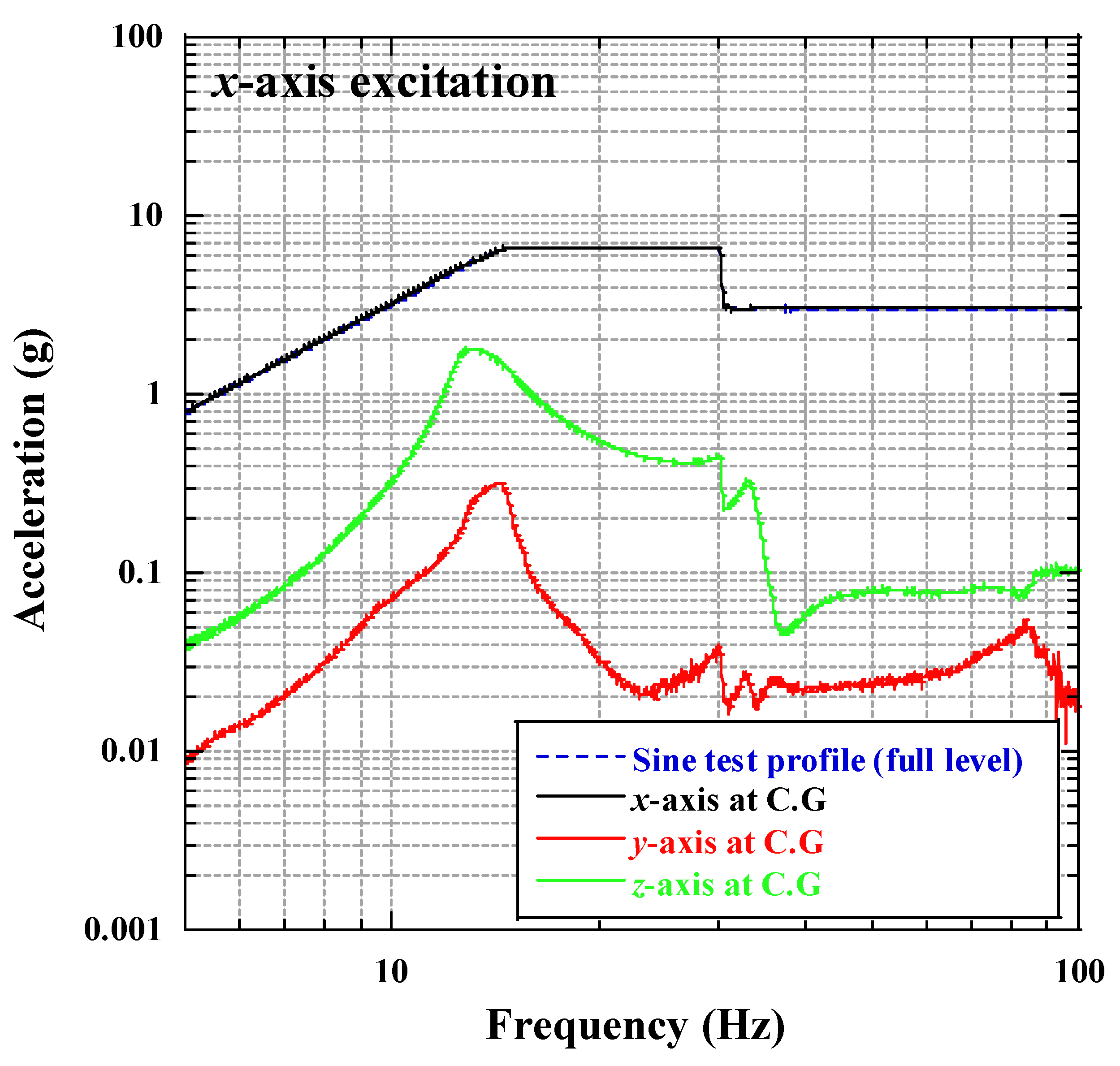
Figure 9 shows the representative sine vibration test results for the TMCM along the x-axis excitation. The test results indicate that the responses of the mechanism along the directions that correspond to the excitation axis follow the test input, without any amplification in the overall frequency range. Only the slight peaks were observed from the responses for the other two axes in the 10~20 Hz region, which were caused by the rigid rotational mode of the driving part, as observed from the modal analysis results in Section 3. This result indicates that the mass balancing strategy combined with the additional force and torque effectively minimizes the rotational movement of the driving part.
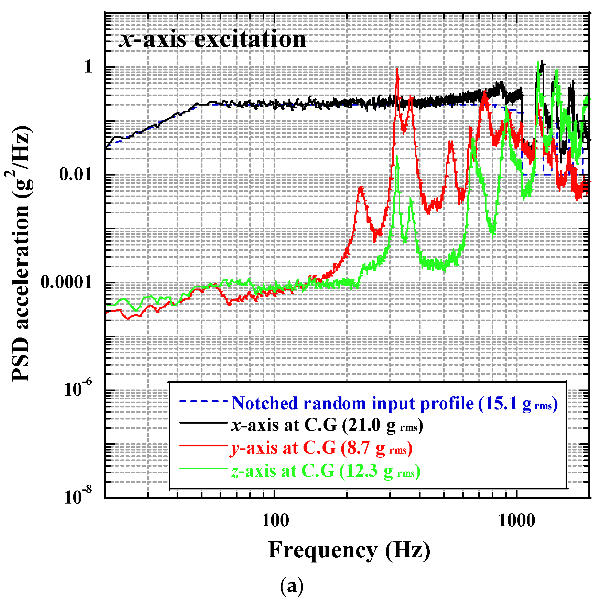
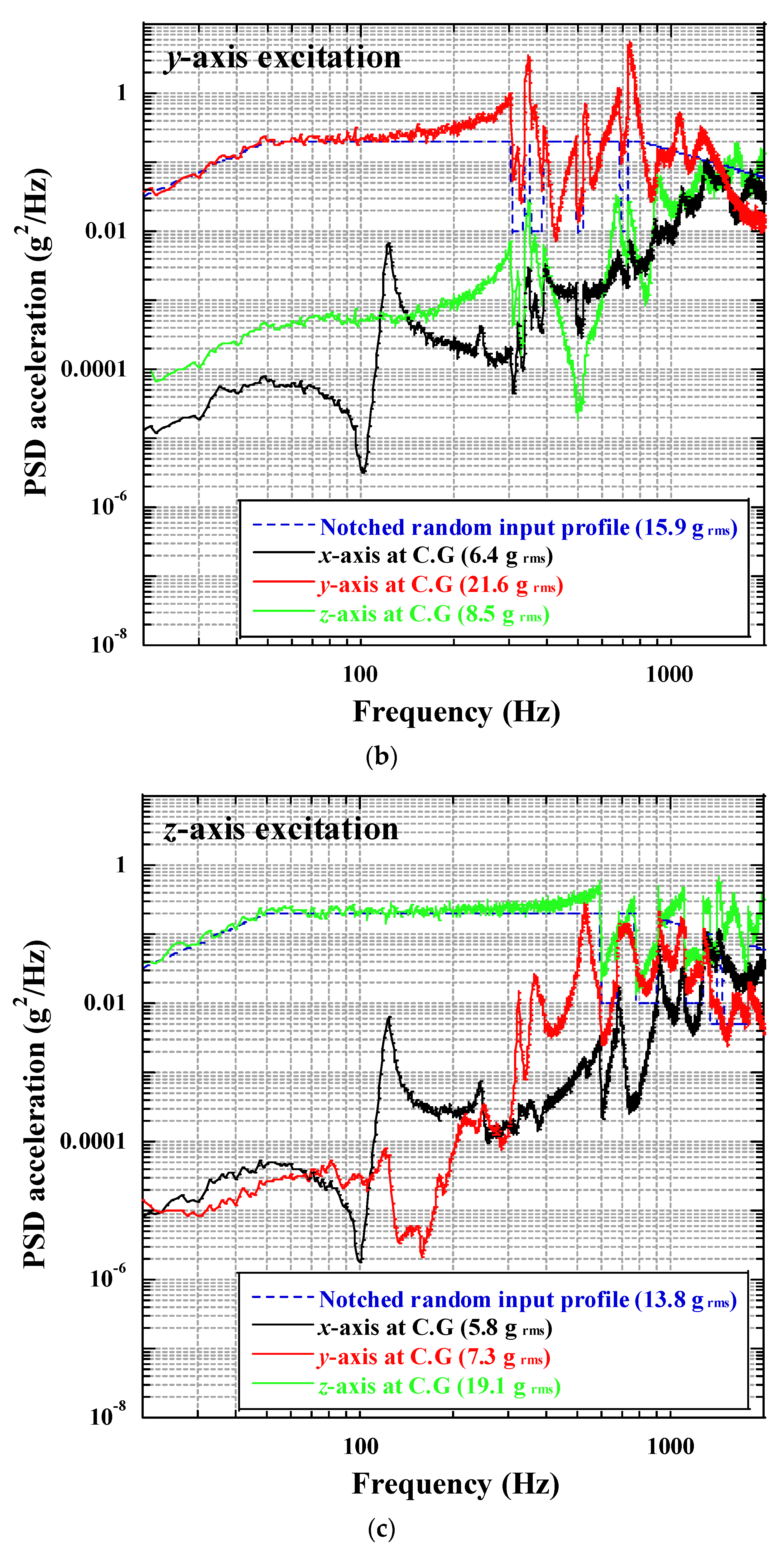
Figure 10a–c show the results of the random vibration tests of the TMCM along each axis. All these test results indicate that the rigid rotational mode, 17.8 Hz, of the TMCM predicted from the structural analysis was not observed in the random vibration tests because the excitation frequency was higher than 20 Hz. Regarding Figure 10a, the x-axis response was first amplified at more than 800 Hz, which is the elastic mode of the TMCM. This means that the mass balancing strategy and actively conjugating the additional pre-loads are effective for minimizing the behavior of the TMCM. Figure 10b,c show almost similar tendencies. In particular, the first peak of the x-axis response was observed at 140 Hz, which was predicted to be the third mode of the TMCM. The measured output grms values in the directions corresponding to the excitation axes were 21.0, 21.6, and 19.1 for each axis. The 3-sigma values of these grms responses indicated that the mechanism was properly tested with respect to the design load of 50 g, although the values were exceeded to some extent.
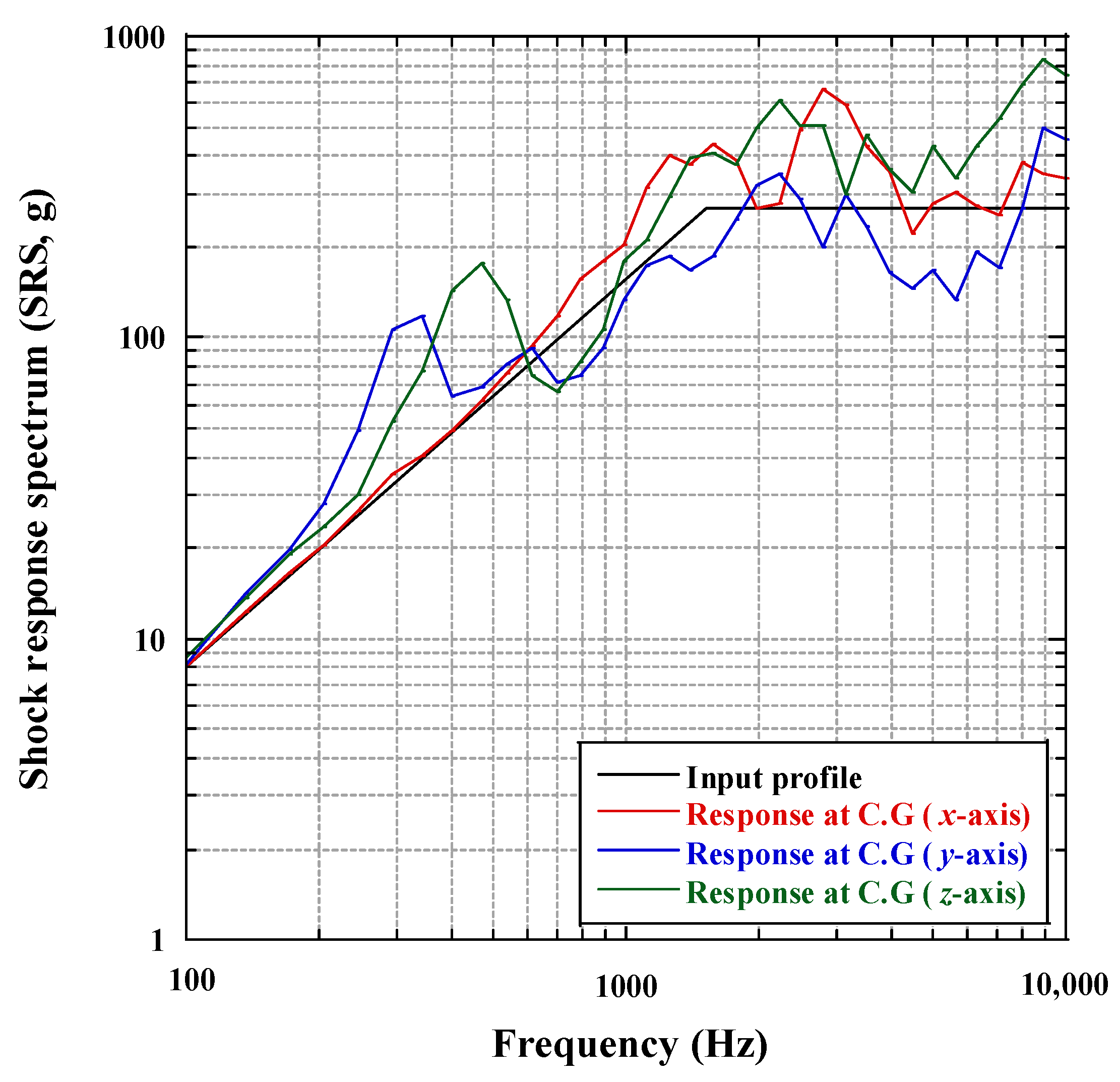
Figure 11 shows the shock test results of the TMCM along each axis. Shock test loads were implemented using a vibration shaker. The input profiles of the shock response spectrum (SRS) were measured at the base of the mechanism. This graph indicates that a maximum of 980 g of SRS was applied to the mechanism in each axis.
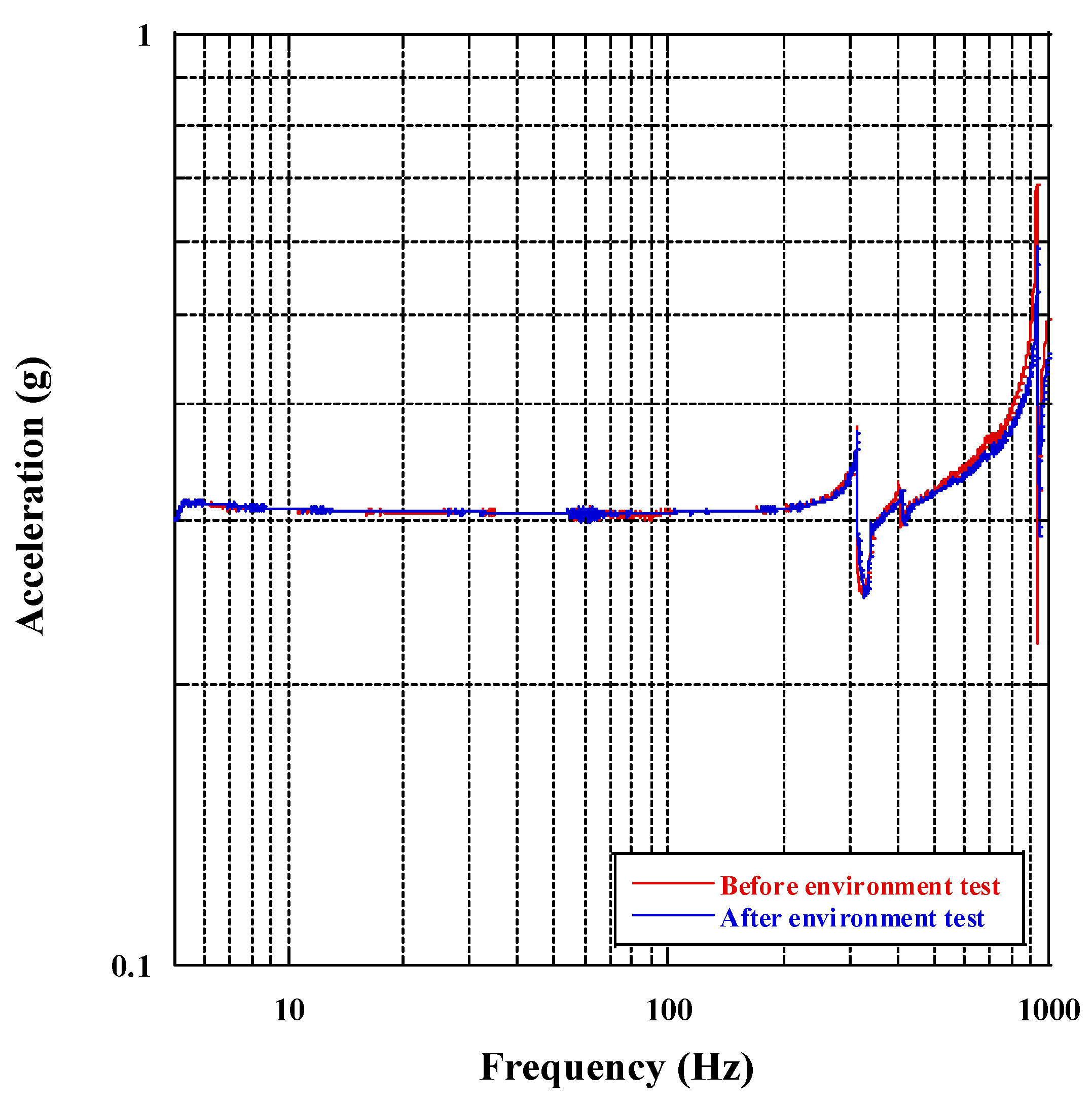
Figure 12 shows the representative results of the low-level sine sweep (LLSS) test on the x-axis of the TMCM before and after the launch environment tests. Table 3 summarizes the 1st eigenfrequencies of the mechanism obtained from the LLSS tests on each axis. The maximum variation of the 1st eigenfrequency of the mechanism in the vibration tests was only 0.69%, which is within 5% of the test requirement. These test results indicate that the structural safety of the proposed TMCM in a launch environment was successfully validated.
To ensure the lifetime of the TMCM during the on-orbit operation, a life cycle test was performed using the same test setup as shown in Figure 6. A total of 23,154 cycles of repetitive deploy-stow actions of the tilt mirror were performed. The number of cycles applied in the test was estimated by the summation of cycles accumulated during on-ground tests and on-orbit operations in accordance with the ECSS rule [
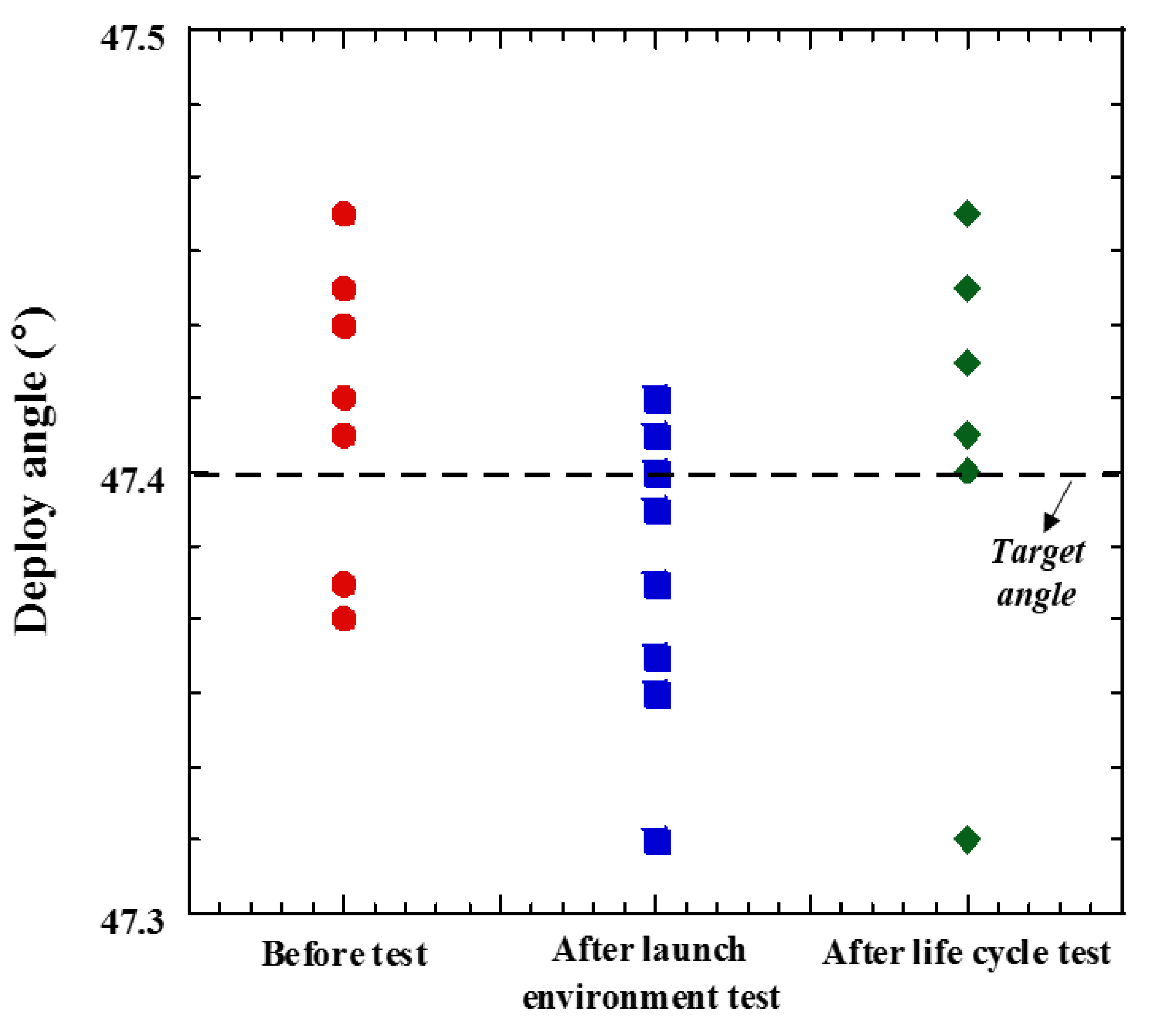
15]. The test results indicated that the TMCM functioned well without any malfunction or failure during the test. After completion of the life cycle test, the measured deployment angle of the mirror was compared with that before the tests to check any performance degradation of the mechanism, because of the accumulated stress on it. Figure 13 shows the deployment angle measured after completing the launch environment and life cycle tests. The results obtained before these tests are also plotted in the figure. The maximum variation in deployment angles among the measured conditions was ±0.12°, which is within the angular tolerance range of ±0.35°, which indicates that there was no performance degradation in the mechanism after each test. Consequently, all the test results indicate that the proposed TMCM with mass balance strategy guarantees structural safety under the launch environment and functionality on-orbit.

5. Conclusions

In this study, a tilting mirror calibration mechanism with a mass balancing strategy was proposed and investigated to ensure the structural safety of the mechanism in a launch environment, although the launch lock mechanism was not applied to the tilt mirror. The main functions of the TMCM are to deploy a mirror in calibration mode, and to stow it after calibration or emergency situations, to avoid blocking the main optical path for imagery. To validate the functionality of the mechanism, an operational function test was performed. In addition, qualification level launch environment tests were performed to validate whether the proposed design based on the mass balancing strategy was effective in ensuring the structural safety of the mechanism during launch. The on-orbit lifetime of the mechanism was also validated by a life cycle test. The overall test results indicated that the design strategy proposed in this study is effective in achieving the design goals of the mechanism.

Author Contributions

Conceptualization, H.-Y.K. and M.-S.J.; methodology, H.-Y.K. and M.-S.J.; software, Y.-H.P. and H.-U.O., formal analysis, Y.-H.P. and H.-U.O.; validation, H.-Y.K. and M.-S.J.; writing-original draft preparation, Y.-H.P.; writing-review and editing, H.-U.O.; Project administration, D.-H.K.; supervision, H.-U.O.; funding acquisition M.-S.J. and H.-U.O.; All authors have read and agreed to the published version of the manuscript.

Funding

This work was funded by a Grant-in-Aid for HANWHA SYSTEMS.

Institutional Review Board Statement

Not applicable.

Informed Consent Statement

Not applicable.

Data Availability Statement

The data used to support the findings of this study are available from the corresponding author upon request.

Acknowledgments

This work was supported by a Grant-in-Aid for HANWHA SYSTEMS.

Conflicts of Interest

The authors declare that they have no competing interests.

References

  1. Walton, C.C.; Sullivan, J.T.; Rao, C.R.N.; Weinreb, M.P. Corrections for detector nonlinearities and calibration inconsistencies of the infrared channels of the advanced very high resolution radiometer. J. Geophys. Res. Space Phys. 1998, 103, 3323–3337. [Google Scholar] [CrossRef] [Green Version]
  2. Bremer, J.C. Alternative blackbody configurations for infrared calibration of future GOES imagers and sounders. In International Symposium on Optical Science and Technology, Earth Observing Systems VII; SPIE: Bellingham, WA USA, 2002; Volume 4814, pp. 183–193. [Google Scholar]
  3. Ono, A.; Sakuma, F.; Arai, K.; Yamaguchi, Y.; Fujisada, H.; Slater, P.N.; Thome, K.J.; Palluconi, F.D.; Kieffer, H.H. Preflight and In-Flight Calibration Plan for ASTER. J. Atmos. Ocean. Technol. 1996, 13, 321–335. [Google Scholar] [CrossRef] [Green Version]
  4. Sapritsky, V.I.; Mekhontsev, S.N.; Prokhorov, A.V.; Sudarev, K.A.; Khromchenko, V.B.; Samoilov, M.L. Precision large-area low- and medium-temperature blackbody sources. In SPIE’s International Symposium on Optical Science, Engineering, and Instrumentation; SPIE: Bellingham, WA USA, 1998; Volume 3437, pp. 434–445. [Google Scholar]
  5. Xiong, X.; Chiang, K.; Esposito, J.; Guenther, B.; Barnes, W. MODIS on-orbit calibration and characterization. Metrologia 2003, 40, S89–S92. [Google Scholar] [CrossRef]
  6. Olschewski, F.; Ebersoldt, A.; Friedl-Vallon, F.; Gutschwager, B.; Hollandt, J.; Kleinert, A.; Monte, C.; Piesch, C.; Preusse, P.; Rolf, C.; et al. The in-flight blackbody calibration system for the GLORIA interferometer on board an airborne research platform. Atmos. Meas. Tech. 2013, 6, 3067–3082. [Google Scholar] [CrossRef] [Green Version]
  7. Oh, H.-U.; Shin, S.; Kim, J.-M. On-Orbit Performance Prediction of Black Body Based on Functional Test Results under Ambient Condition. J. Aerosp. Eng. 2012, 25, 39–44. [Google Scholar] [CrossRef]
  8. Oh, H.-U.; Jo, M.-S.; Lee, K.-M.; Kim, D.-J. Spaceborne Tilt Mirror Mechanism and Application of Shape Memory Alloy Actuator to Implement Fail-safe Function in Emergency Mode. Trans. Jpn. Soc. Aeronaut. Space Sci. 2012, 55, 373–378. [Google Scholar] [CrossRef] [Green Version]
  9. Suchman, J.; Salinas, Y.; Kubo, H. MIRO calibration switch mechanism. In Proceedings of the 35th Aerospace Mechanisms Symposium, Mountain View, CA, USA, 9–11 May 2001; pp. 179–184. [Google Scholar]
  10. Available online: http://www.tiniaerospace.com (accessed on 12 June 2021).
  11. Schmid, J. The SEVIRI instrument. In Proceedings of the 2000 EUMETSAT Meteoro-logical Satellite Data User’s Conference, Bologna, Italy, 29 May–2 June 2000; Volume 29, pp. 23–32. [Google Scholar]
  12. Compostizo, C.; Sacristán, A.; Larrabeiti, E.; Angulo, I. MTG Scan Launch Locking Mechanisms. ESA Spec. Publ. 2015, 737, 40. [Google Scholar]
  13. Oh, H.-U.; Lee, M.-J.; Kim, T. Experimental Design Validation of Tilting Calibration Mechanism by Using Shape Memory Alloy Spring Actuator. Int. J. Aerosp. Eng. 2017, 2017, 1–12. [Google Scholar] [CrossRef] [Green Version]
  14. Liu, Q.; Wang, K.; Yuan, R.; Peng, P. Novel repeatable launch locking/unlocking device for magnetically suspended momentum flywheel. Mechatronics 2018, 54, 16–25. [Google Scholar]
  15. Zhang, X.; Yan, X.; Zhang, S.; Nie, J. Development of a novel shape memory alloy-actuated resettable locking device for magnetic bearing reaction wheel. Rev. Sci. Instrum. 2014, 85, 1–8. [Google Scholar] [CrossRef] [PubMed]
  16. European Cooperation for Space Standardization (ECSS-Q-ST30-02C). In Space Product Assurance, Failure Modes, Effects (and Criticality) Analysis (Fmea/Fmeca); ESA-ESTEC: Noordwijk, The Netherlands, 6 March 2009.
  17. European Cooperation for Space Standardization (ECSS-E-ST33-01C)-Mechanism; ESA-ESTEC: Noordwijk, The Netherlands, 2009.
  18. Macchanhaoil, M. Static and dynamic balancing of rigid rotors. Bruel Kjaer Appl. Notes 2016, 1–20. Available online: https://dokumen.tips/documents/bruel-kjaerstatic-and-dynamic-balacing-of-rigid-rotor.html (accessed on 1 July 2021).
Figure 1. Operation concept of the proposed tilting mirror mechanism. (a) Calibration mode, (b) Imaging mode, and (c) Emergency mode.
Aerospace 08 00284 g001aAerospace 08 00284 g001b
Figure 2. Configuration of tilting mirror calibration mechanism (TMCM) (a) Isometric view, (b) Side view.
Aerospace 08 00284 g002aAerospace 08 00284 g002b
Figure 3. Operation principle of fail-safe function.
Aerospace 08 00284 g003
Figure 4. Variation of the 1st eigenfrequency and rotational angle according to the preloaded conditions.
Aerospace 08 00284 g004
Figure 5. Mode shape of modal analysis results (a) 1st mode (17.3 Hz), (b) 2nd mode (92.4 Hz), (c) 3rd mode (158.6 Hz), (d) 4th mode (240.8 Hz).
Aerospace 08 00284 g005
Figure 6. Operational function test set-up of TMCM.
Aerospace 08 00284 g006
Figure 7. Launch environment test set-up of TMCM.
Aerospace 08 00284 g007
Figure 8. Comparison results of random vibration tests for TMCM with HRM [8] and the TMCM without the HRM proposed in this study (a) in x-, (b) y-, and (c) in z-axis.
Aerospace 08 00284 g008aAerospace 08 00284 g008b
Figure 9. Sine vibration test results of TMCM in x-axis.
Aerospace 08 00284 g009
Figure 10. Random vibration test results of TMCM in (a) x-, (b) y-, and (c) z-axes.
Aerospace 08 00284 g010aAerospace 08 00284 g010b
Figure 11. Shock test results of TMCM in each axis.
Aerospace 08 00284 g011
Figure 12. Low level Sine Sweep results.
Aerospace 08 00284 g012
Figure 13. Measured deployed angles before and after each test.
Aerospace 08 00284 g013
Table 1. Torque budget estimation results for tilting mirror calibration mechanism.
ParametersValues (Nm)Remark
Tl0.137Limit switches: 2 EA
Tc0.382
Tb0.042Angular contact bearing: 2 EA
Radial bearing: 1 EA
Tg0.830
Tacc0.0004
Td0.253
Tm3.325Required torque on the motor
Table 2. Qualification level of launch environmental test specifications.
(a) Random Vibration
ItemSpecification
Axisx, y, z
RMS acceleration14.1 grms
Duration2 min
Acceleration profileFrequency (Hz)PSD acceleration (g2/Hz)
20–500.0226
50–8000.1413
800–20000.0424
(b) Sine Vibration
ItemSpecification
Axisx, y, z
Sweep rate2 oct/min
Acceleration profilex and y-Axisz-Axis
Frequency (Hz)Acceleration (g)Frequency (Hz)Acceleration (g)
5–12±8 mm5–12±9.2 mm
12–306.512–309
30–100330–1006.5
(c) Shock
ItemSpecification
Axisx, y, z
SRS profileFrequency (Hz)SRS (g)
1008
1515270
10,000270
Table 3. Summary of low-level Sine sweep test results for TMCM.
TestAxis1st Eigenfrequency (Hz)Variation (%)
Sine vibrationxBefore310.250.01
After310.28
yBefore392.500.69
After389.79
zBefore704.020.34
After701.59
Random vibrationxBefore310.280.06
After310.10
yBefore392.500.34
After391.14
zBefore701.590.68
After696.75
Publisher’s Note: MDPI stays neutral with regard to jurisdictional claims in published maps and institutional affiliations.

