Article

Development of the EIRSAT-1 CubeSat through Functional Verification of the Engineering Qualification Model

by
Sarah Walsh
1,*,
David Murphy
1,
Maeve Doyle
1,
Jack Reilly
1,
Joseph Thompson
2,
Rachel Dunwoody
1,
Jessica Erkal
1,
Gabriel Finneran
1,
Gianluca Fontanesi
2,
Joseph Mangan
1,
Fergal Marshall
1,
Lána Salmon
1,
Daithí de Faoite
2,
Lorraine Hanlon
1,
Antonio Martin-Carrillo
1,
David McKeown
2,
William O’Connor
2,
Alexey Uliyanov
1,
Ronan Wall
1 and
Sheila McBreen
1
1
School of Physics, University College Dublin, Belfield, Dublin, Ireland
2
School of Mechanical and Materials Engineering, University College Dublin, Belfield, Dublin, Ireland
*
Author to whom correspondence should be addressed.
Aerospace 2021, 8(9), 254; https://doi.org/10.3390/aerospace8090254
Submission received: 5 August 2021 / Revised: 29 August 2021 / Accepted: 5 September 2021 / Published: 8 September 2021
(This article belongs to the Special Issue Small Satellite Technologies and Mission Concepts)

Abstract

:
The Educational Irish Research Satellite (EIRSAT-1) is a 2U CubeSat developed at University College Dublin. The project aims to build, test, launch, and operate Ireland’s first satellite and to perform in-orbit demonstrations of three novel payloads developed in-house. To reduce risk within the mission, the project employs a prototype model philosophy in which two models of the spacecraft exist: an engineering qualification model (EQM) and a flight model (FM). This paper presents the verification approach of the functional tests implemented for the EIRSAT-1 project. The activities of the FlatSat and system level full functional tests of the EQM are presented and the results obtained during the test campaigns are discussed. Four test anomalies were encountered during the full functional test campaign resulting in two minor redesigns, and subsequent reassembly, of the CubeSat. The functional test campaigns highlighted the importance of FlatSat level testing of CubeSats to ensure compatibility of all subsystems prior to assembly and of thorough documentation to diagnose any unexpected behaviour of the hardware efficiently. The functional verification of the EQM proved that the system conformed to its design, verifying 57 mission requirements, and is a crucial step towards the development of the EIRSAT-1 FM.

1. Introduction

CubeSats are miniature satellites developed in the early 2000s [1] and designed using a standardised CubeSat ‘unit’—a 1U. They conform to a standard size of 10 cm × 10 cm × 10 cm and a mass less than 1.33 kg per unit [2] with larger configurations of 2U, 3U, 6U, and 12U possible. Originally proposed to provide space access to the university scientific community [3,4], the concept of CubeSats has been endorsed by the space industry [5], with many space agencies and commercial groups adding CubeSat missions to their fleets of spacecraft [6,7,8,9]. Many are being deployed as in-orbit demonstrators or as proof-of-concept missions to qualify new technologies for space. Their low-cost, fast delivery timescale, attributed to their standardised design, has resulted in an exponential growth in their popularity with over one thousand CubeSats launched since their inception [10,11,12]. However, a large percentage of missions are found to fail on launch or during early operations, particularly missions from university teams rather than those from commercial groups or space agencies. This is likely attributed to a lack of verification and validation (V&V) activities due to constraints on resources, experience, or schedule within these small scale projects [13,14].
Similar to any large-scale satellite, albeit on a scaled down level, CubeSats should undergo robust V&V to reduce the risk involved in a space mission. This refers to verifying that the system conforms to a predefined set of requirements and by validating that the system can perform the intended mission. Key phases in the life cycle of any space mission are ‘Phase C–Detailed Definition’ and ‘Phase D–Qualification and Production’ [15]. During these phases, the development of the system through qualification or acceptance verification and testing is performed and the preparation for mission operations is finalised. A core activity during these phases includes functional testing. Defined by ECSS standard ECSS-E-ST-10-03C [16], a full functional test (FFT) is a “comprehensive test that demonstrates the integrity of all functions of the item under test, in all operational modes” whose main objectives are to “demonstrate absence of design manufacturing and integration error”. It demonstrates the ability of the spacecraft to conform to its technical requirements and verifies the overall functionality of the system. Therefore, a robust and detailed functional test, supported by mission, performance, or end-to-end testing, can lead to increased mission survival rates.
The importance of the V&V process for CubeSat projects is becoming more apparent among missions, including university projects, and is reflected in the reduced failure rates of CubeSat missions in recent years and the adaptation of ECSS Standards for CubeSat missions [17]. Multiple university projects are implementing robust testing methods to provide reliability to their mission and ensure mission success. One method suggested is a fault injection technique, implemented by NanosatC-BR-2 [18], whereby software and hardware faults are injected into the system and subsequently cause a failure from which it has to recover. Cheong et al. [19] propose a minimal set of robustness tests that were developed following their experience with a communication failure at the early stage of the mission that lead to a root cause analysis investigation and recovery of the spacecraft. Multiple projects [20,21] report using hardware-in-the-loop (HIL) methods to verify the full functionality of the system while InflateSail at the University of Bristol [22] perform functional and qualification testing on individual subsystems prior to integration at system level. A CubeSat team from the Instituto Superior Técnico in Portugal opted to design the majority of their subsystems in-house for full control over design and test activities and implement an iterative prototyping approach to verify subsystems at FlatSat level [23]. The Aalto-1 project, developed at Aalto University, employed a FlatSat-engineering qualification model (EQM)-flight model (FM) approach given the complex development of in-house subsystems and payloads within an university project [24]. Implementation of these methods within university CubeSat projects have and will continue to increase the success of missions, while educating students on the V&V strategies in the process.
The Educational Irish Research Satellite (EIRSAT-1) [25], shown in Figure 1, is a 2U CubeSat project led by students at University College Dublin (UCD), with support from academics and industry partners, that aims to design, build, launch, and operate Ireland’s first satellite. The project is supported by the Fly Your Satellite! (FYS!) programme [26] of the European Space Agency′s (ESA′s) Education Office [27,28]. The mission incorporates three payloads developed at UCD; a gamma-ray detector, the Gamma-ray Module (GMOD) [29,30]; a thermal coating management experiment, the Enbio Module (EMOD); and an attitude control algorithm, Wave-Based Control (WBC) [31]. In addition to the payloads, a custom antenna deployment module (ADM) is being developed for the mission at UCD [32]. These payloads are supported by commercial off-the-shelf (COTS) components supplied by AAC Clyde Space, such as the communications transceiver, battery, electrical power supply (EPS), attitude determination and control system (ADCS), on-board computer (OBC), solar panels, and magnetorquers. The on-board software for the mission is developed using Bright Ascension’s GenerationOne flight software development kit [33].
The mission has a number of scientific goals and will perform the first in-orbit demonstration of the three novel payloads with aims to detect gamma-ray bursts (GRBs) [34], to demonstrate the efficiency of SolarWhite [35] and SolarBlack [36] thermal coatings in low Earth orbit (LEO), and to test novel attitude control algorithms [37]. The primary payload, GMOD, will provide an in-orbit demonstration of technologies that could advance the next generation of spaceborne gamma-ray instruments by incorporating the use of a CeBr 3 crystal with a silicon photomultiplier (SiPM) array in LEO [30]. SolarBlack and SolarWhite thermal coatings have been incorporated into ESA′s Solar Orbiter mission [38] but EIRSAT-1 will provide the first demonstration of these coatings in LEO by monitoring the temperature of four coated aluminium panels on the spacecraft throughout the mission.
In recent years, the term ‘lean satellite’ has been developed to describe missions that take unconventional risks during their development to achieve a low-cost and fast delivery [39]. The approach focuses on the use of non-qualified COTS components to achieve a lower cost and shorter schedule, which typically leads to a smaller size. The inherited risks associated with this concept are accepted, and the reliability of the mission is superseded by the project cost and schedule. Many satellites fall within the scale from a traditional satellite (those that follow strict standards and requirements) to a lean satellite, depending on the level of risk a mission will accept and the budget that a project can meet. A study on the lean satellite concept showed that university teams tend to avail of this approach, taking more risk within their missions [40]. Given the complexity of the EIRSAT-1 mission with three in-house development payloads and a lack of experience within a student led team developing Ireland’s first satellite, the project implements a robust verification approach, veering away from the lean satellite concept. It implements a similar philosophy to that of Aalto-1 [24], whereby an EQM and FM of the system exist and both undergo rigorous test campaigns. Test plans for the EIRSAT-1 project involve ambient and environmental test campaigns for both models, which include functional, mission, vibration, and thermal vacuum testing. In addition, all hardware is functionally tested in a FlatSat configuration prior to system level integration. This approach aims to reduce risk and to demonstrate reliability, prior to launch, that the system can achieve its mission objectives.
In this paper, the verification and testing approach of the EIRSAT-1 EQM is presented. In Section 2, the main aspects of the assembly, integration, and verification (AIV) plan of EIRSAT-1 are discussed and how these aim to reduce risk within the project. Section 3 provides an overview of the main functional tests performed on the EQM, with particular focus on the FlatSat functional test campaign (Section 3.1) and FFT campaign (Section 3.2). The key results from both campaigns are presented and the lessons learnt from these results are discussed in Section 4. Finally, a summary and the plan for future work is given in Section 5 and Section 6.

2. Assembly, Integration, and Verification of EIRSAT-1

Within the FYS! programme, the verification plan (VP) and assembly, integration, and test (AIT) plan are combined into a single AIV plan, which is also possible under ECSS Standards [41]. The purpose of this plan is to outline and demonstrate how the objectives and requirements of the mission will be verified by documenting all AIV activities that will be performed. Given that EIRSAT-1 aims to fly three complex and novel payloads developed by a student led team with limited experience, significant risk is introduced to the project. Various CubeSat projects implement risk reduction processes such as fault tree analysis (FTA), failure mode and effects analysis (FMEA), failure mode, effects, and criticality analysis (FMECA), or risk response matrix (RRM) [42,43,44]. Similar measures are implemented in the EIRSAT-1 project by maintaining a risk register, whose purpose is to identify risks, and develop strategies to mitigate them, conducting structural and thermal analysis, and implementing fault detection, isolation, and recovery (FDIR) methods during the EIRSAT-1 software development and mission test [45] to manage risks for the mission. However, the primary modes of risk reduction for project is by two aspects of its AIV plan: its model philosophy and rigorous test campaigns.
First, EIRSAT-1 employs a ‘prototype’ model philosophy [46] whereby an EQM and FM of the spacecraft exist [47]. Additionally, development models (DMs) exists for the in-house developed items, GMOD, EMOD, and the ADM. This philosophy offers the project low risk, the completion of qualification activities prior to acceptance, and the ability to use the EQM as a integration spare or an in-orbit debugging tool. However, it introduces additional costs and lends to a longer schedule as all hardware must be procured twice over and test campaigns are conducted on both models. As a result, many university CubeSat teams opt to implement a protoflight model (PFM) philosophy whereby a single model is produced and flown after it has been subjected to protoflight qualification and acceptance test campaigns. Typically these projects rely on significant flight heritage or a robust CubeSat bus so that the associated risk is accepted [43,48,49]. In the case of EIRSAT-1, the increased risk of the PFM approach was not deemed acceptable due to the lack of experience among the team.
This model philosophy is illustrated in Figure 2, showing the existence of the three models at various levels of the spacecraft. All DMs undergo a series of iterations to the final design, as discussed in Walsh et al. [47]. For the EQM, these components undergo functional testing following their assembly and an environmental test campaign to qualification levels [50]. Subsystem level environmental testing is not performed at FM provided the design of the FM subsystem is within the same structural specification as that qualified for the EQM. COTS components are assumed to have undergone sufficient testing by the manufacturer and so are subject to brief functional, or acceptance, testing on arrival at UCD prior to being integrated into the system.
The EQM of the spacecraft combines the traditional engineering model (EM) and qualification model (QM) into a single entity and is identical in design of the FM with the exception of having no solar cells due to cost constraints. Both the EQM and FM are subject to ambient and environmental testing at system level. The EQM undergoes environmental test campaigns to qualification levels to provide evidence that the spacecraft conforms to requirements when subject to the worst case levels predicted of vibration and temperature. The FM is tested to acceptance levels so as to not induce any additional stress on the flight unit while ensuring that the spacecraft can operate when subjected to the maximum levels of vibration and temperature expected to be encountered during launch and orbit.
Second, as required by the FYS! programme, EIRSAT-1 will undergo rigorous and robust system level testing through integration tests, functional tests, mission tests, and environmental tests. These tests aim to ensure reliability of the spacecraft and to verify mission requirements. A detailed view of the test campaigns that are executed on the EQM and FM at system level is shown in Figure 3. This shows three main sections of the system level AIV plan:
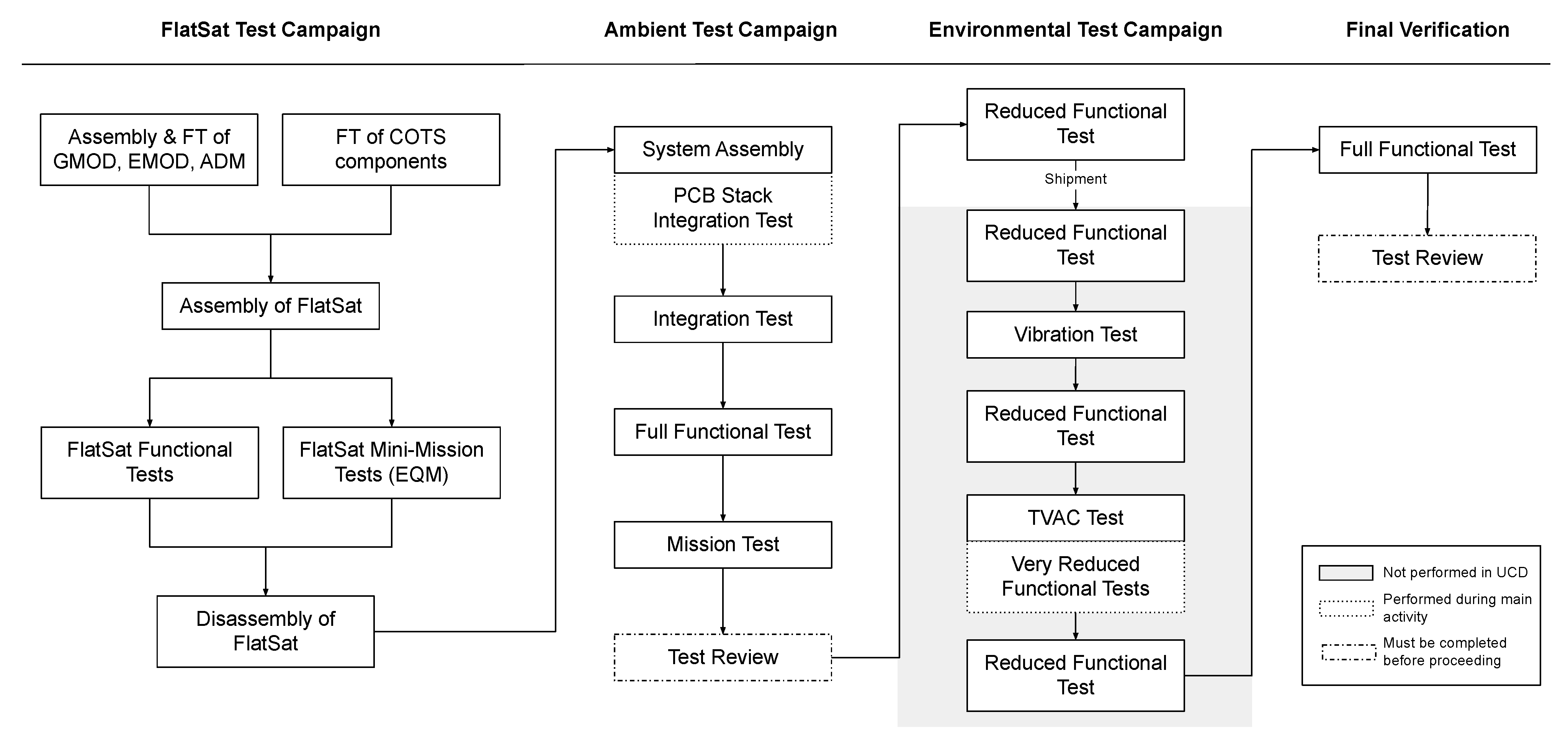
  • the FlatSat assembly and test campaign,
  • the system level assembly and ambient test campaign, and
  • the system level environmental test campaign.
The main objective of the FlatSat campaign is to verify the electrical integration of all subsystems, prior to the system level assembly and integration. The main advantage of performing this campaign prior to assembly is that all hardware is accessible to test operators in the FlatSat configuration (see Figure 4), so that anomalies or hardware issues can be probed with ground support equipment (GSE) and assessed without have to perform a disassembly of the spacecraft. The technique of FlatSat testing can be implemented in CubeSat projects to provide an initial verification of the system [23,24,51] and is implemented in the EIRSAT-1 project for both the EQM and FM. Once performed, the system is assembled into flight configuration, as in Figure 5, in line with the assembly and integration procedure (AIP) of EIRSAT-1, described in Walsh et al. [47]. During the assembly procedure, a brief integration test is performed on the printed circuit board (PCB) stack (Figure 1) once all major electrical connections of the spacecraft have been integrated. This test verifies the electrical connections in the PCB stack and that the spacecraft bus is operational, allowing the power up of all subsystems. The integration test is repeated once the full system assembly has been complete. The ambient test campaign of EIRSAT-1 consists of two major tests required within the FYS! programme: the FFT and the mission test [45]. Following a review of this campaign by the team and by members of the FYS! programme, the project moves to the environmental test campaign, during which vibration testing and thermal vacuum testing are performed to ensure the system is capable of withstanding the harsh conditions of space. Given the required test equipment, this test campaign is not performed at UCD but at the ESA Education CubeSat Support Facility. Throughout the environmental test campaign, reduced functional tests (RFTs) are performed, the purpose of which is to verify the major functions of the spacecraft in a relatively short period of time. It is performed directly before and after any shipment of EIRSAT-1 and in between thermal vacuum (TVAC) and vibration testing. The test offers a high degree of confidence that no damage occurred during intense periods of stress on the spacecraft. In addition, a series of very reduced functional tests (VRFTs) are performed throughout the thermal vacuum campaign to ensure the spacecraft remains operational at the hot and cold dwells. Following the completion of the environmental test campaign, the spacecraft is subject to another FFT to verify no damage has occurred during the campaign or the subsequent shipment from the test facility. The results of this functional test should be identical, within the test tolerances, to the test performed in the ambient test campaign.

3. EIRSAT-1 Functional Tests

As highlighted in Figure 3, functional tests are performed at multiple stages during the development and verification of EIRSAT-1. At all stages, these functional tests aim to verify the functionality and the requirements of the system. There are four key types of functional tests that occur during the development of EIRSAT-1: the FlatSat functional test, the FFT, RFT, and the VRFT.
Table 1 lists the functional test activities that are performed during the EQM functional test campaigns of EIRSAT-1 for each subsystem. The majority of tests—with the exception of two that are performed at FlatSat level only due to access requirements—are performed during the system-level FFT of EIRSAT-1. The reduced functional test consists of a subset of these, primarily focused on hardware functions that are crucial to the mission. The very reduced functional test executes an even smaller subset of functional tests activities and provides a functional health check of the spacecraft during the TVAC test campaign. The activities during the RFT and VRFT are typically shortened compared to the duration of the activity during the full functional test and FlatSat tests. The test activities envisaged for the FM are nearly identical to that of Table 1 but with a few minor changes required due to time and resource constraints during the EQM development. This includes not performing WBC test activities on the EQM (FlatSat or system), but given that this is a software payload, the team have accepted the associated risk. Selected battery tests are performed on the EQM only to reduce the risk of significant battery degradation to the FM. The ADM and EMOD thermal coupon assembly (TCA) were not available at the time of the EQM FlatSat test campaign and so were not integrated to the FlatSat but instead were replicated with ground support equipment. This had implications for the results of the full functional test which are discussed in Section 3.2 and Section 4.

3.1. FlatSat Test Campaign

The FlatSat assembly and test campaign is performed on both the EQM and FM hardware before assembly and integration of the full system. The FlatSat test campaign consists of both functional tests from Table 1 and a series of short mission scenario simulations, called ‘mini-mission’ tests. The functional tests provide an initial verification of all subsystems when electrically integrated in a flight configuration and are performed on both the EQM and FM FlatSats. The mini-mission tests are only performed on the EQM FlatSat and allow for the initial development of the operational procedures and manual for EIRSAT-1 [52]. The FlatSat functional test is not a requirement of the Fly Your Satellite! programme but is performed for the EIRSAT-1 project to reduce risk and to gain experience interacting with the hardware.

3.1.1. Test Prerequisites
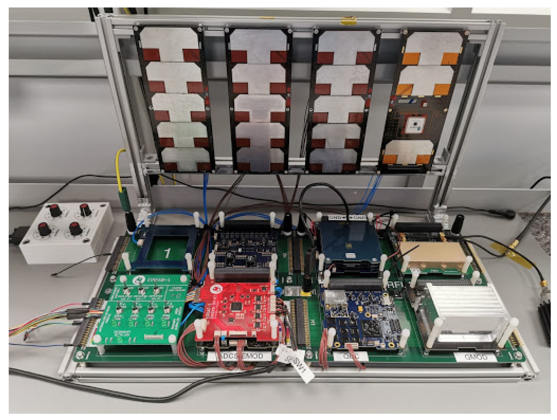
Prior to the FlatSat test campaign, all subsystems must undergo brief functional or acceptance testing. In the case of GMOD, EMOD, and the ADM, their individual assembly must be performed at UCD prior to this testing. Once the COTS hardware has been received and accepted in UCD, each subsystem undergoes a short series of functional and acceptance tests. Once all subsystems have passed their basic tests, the FlatSat can be assembled.

3.1.2. Test Setup

Figure 4 shows the EQM hardware of EIRSAT-1 in the FlatSat configuration. It consists of all EQM COTS components, the EQM GMOD motherboard and detector assembly, and the EQM EMOD motherboard. The ADM and EMOD TCA is not present on the EQM FlatSat but is represented by a FlatSat add-on board of melt-line resistors, called EIRFAB, and a dummy TCA of temperature controls, respectively. EIRFAB also hosts hand operated electrical switches to replicate the deployment and separation switches of the system.
To support the FlatSat test campaign, a set of GSE is required. This includes a power breakout board, an interface to connect a power supply unit and to monitor bus voltages; a data breakout board, allowing for serial communication with the spacecraft OBC and for JTAG programming; and Earth Simulator, an in-house developed software that allows use of realistic in-orbit communication passes and charging cycles. Earth Simulator is also used to control the inhibit switches and remove before flight (RBF) pin of the spacecraft through relays to allow remote working during the COVID-19 pandemic.

3.1.3. Test Results

The test campaign tested functions of the battery, EPS, communications system, ADCS and the OBC are listed in Table 1. No test anomalies were observed during the testing activities, and the spacecraft behaved as expected with nominal results obtained throughout. No tests of the ADM and EMOD TCA hardware were performed during the FlatSat functional tests for the EQM, but instead additional ground support equipment was used to facilitate software based tests of these systems.
The campaign proved to be extremely educational for the team. It was the first interaction with and use of the system hardware, giving the team experience with its handling and operation. In addition, it allowed the finalisation of test documentation in preparation for the system level FFT, which was submitted to members of the FYS! programme to undergo review and to be approved for use during the ambient test campaign. The tests conducted proved the reliability of the electrical integration and compatibility of the subsystems to operate and communicate with each other. Finally, the campaign verified the initial versions of the flight software and allowed further development of the software while allowing access to all subsystems for debugging and probing.

3.2. Full Functional Test Campaign

The FFT forms a major part of the ambient test campaign, or Phase D1, within the FYS! programme and the EIRSAT-1 project. The FFT must be completed before progression to environmental testing, or Phase D2, can be achieved. The test performs all test activities listed in Table 1, with the exception of two indicated tests for the EPS and battery system as they require direct access to the battery header, which is not possible in the flight configuration. The FFT of the EIRSAT-1 EQM began in December 2020 and closed out in July 2021.

3.2.1. Test Prerequisites

Prior to the FFT of EIRSAT-1, the system level assembly was completed, as this test requires the spacecraft to be as configured for flight. An integration test was performed after assembly to confirm nominal basic operations of the subsystems and their electrical integration. A mass and dimensions verification (MDV) and visual inspection of the spacecraft were completed to ensure the system conformed to physical requirements and did not have any visible defects. The FFT campaign has strict documentation and review requirements from the team and the FYS! programme whereby a test specification (TSpe) and test procedure (TPro) must be submitted to FYS! members for review before proceeding with the test. These documents describe the test in its entirety, including the setup, test requirements, required personnel, and the step-by-step instructions to complete each test activity.

3.2.2. Test Set-Up

Figure 5a shows the EQM hardware of EIRSAT-1 in the flight, or system-level, configuration. It consists of all EQM COTS components and the EQMs of the in-house developed payloads, GMOD, EMOD, and the ADM. Test thermocouples are also installed throughout the spacecraft, which are used during thermal vacuum testing, and exit the spacecraft on the –X solar panel through a cut out at the bottom of the panel, which can be seen in Figure 5.
For the majority of the test, the spacecraft is placed in a vertical configuration in an integration stand. It is supported by the same GSE as the FlatSat functional test campaign with the addition of a turntable that is used during ADCS testing (Figure 5b).

3.2.3. Test Results

All test activities in Table 1 were performed during the FFT with the majority of tests producing nominal results. However, four test anomalies were recorded during the test campaign. A test anomaly is defined as an unexpected behaviour of the spacecraft and can often lead to a test failure. Upon occurrence of a test anomaly, a report is produced and an investigation into the anomaly is conducted. If necessary, design changes are implemented to the system and functional tests are subsequently repeated if invalidated by the design change. Given that most test activities were performed nominally, this section will discuss the test anomalies encountered, the results of their investigation, and the corrective actions implemented where required.
The first anomaly was encountered during the functional tests of the ADM subsystem. The ADM has redundant deployment methods whereby the antenna can be released by individual burns of the primary resistors or by simultaneous burns of the secondary resistors, which are connected to switchable power distribution modules (PDMs) 1 and 2 on the EPS, respectively [32]. In orbit, deployment by the primary resistor burns are attempted first, followed by the secondary resistors burns for a duration predefined in the mission software. The FFT verifies both methods of deployment through resistor burns of 30 s duration, during which it is expected that the melt-lines holding the antenna doors will melt and release the antenna elements.
During the test of the antenna deployment by burning of the secondary resistors, the antenna elements failed to deploy within the 30 s. The burn time was increased to attempt deployment for burn times of 60 s and 120 s. During these attempts, some elements were released but not all as expected. This resulted in a fail of the test activity and was recorded as a major anomaly, subsequently launching an anomaly investigation into the root cause of the issue. Upon investigation, it was concluded that thermal dissipation from the secondary resistors due to the design of the ADM PCB was causing the failure.
The secondary resistors were connected directly to the PCB’s ground plane with only small thermal breaks introduced by the PCB layout software designed to aid the soldering process. As a result, the secondary resistors had a good thermal conduction into the ground plane which acted as a heat sink so that the melting temperature of the melt-line was not reached, subsequently preventing the antenna from deploying. This shortcoming was not detected during qualification of the deployment mechanism as the heat sink effect was not significant enough to prevent deployment of the antenna elements in reasonable time frames even at low temperature. Once the issue had been identified during the anomaly investigation, the layout of the ADM PCB was redesigned to give much improved thermal characteristics, greatly reducing the available heat-paths and thermal conduction from the resistors into the PCB.
The second anomaly occurred during the verification of the release detection switches and the RBF pin with which EIRSAT-1 is equipped with. The spacecraft has one RBF pin located on the –X face and three release detection switches, or inhibits, located in the corner rails towards the –Z end of the CubeSat. These switches ensure that the spacecraft does not power on when any one is activated, or in a compressed state. Once all switches are released, the spacecraft powers on, the separation sequence of the mission initiates, an on-board timer begins a 45 min countdown until deployment can occur, and RF transmissions are enabled once the first burn attempt has completed. The test aims to verify these functions of the power system and the on-board timer by reactivating each individual switch to ensure that the spacecraft powers off and, once the switch is reactivated, that the antenna deployment attempts do not happen for a period of 45 min following reactivation.
During the FFT, shortly after RF transmission had been enabled, error messages were observed in a debug terminal. These messages occurred as the OBC attempted to request data from the ADM, whose firmware is hosted on the EMOD motherboard, but received no response. This anomaly did not result in a failure of the test activity, as the objectives of the RBF and inhibit switches were verified, but a major problem was highlighted. Again, an anomaly investigation was launched to determine the root cause of the problem. Reproduction of the anomaly was possible, albeit irregular, when the procedure was conducted in the same manner as the test. The EMOD motherboard could be recovered by a power cycle of the payload but communication with the motherboard would soon after fail again. The failures were found to be coincident with RF transmissions, and a power cycle of the payload failed to recover it once the transmission power of the transceiver was increased. It was concluded that an electromagnetic compatibility (EMC) transient between the ADM PCB and the EMOD motherboard was triggering a failure within the EMOD motherboard, upon an RF transmission, and preventing the OBC receiving the requested data from the ADM. This anomaly had not been detected during previous testing as no tests had been conducted on the EQM with RF transmission turned on. Through experimentation, it was determined that the transient was only coupled through the two lines in the ADM harness which connected the two deployment switches closest to the UHF antenna elements. Furthermore, it was observed that it only occurred when the switches were not pressed. In the pressed state, the effected lines are grounded through the switches’ normally closed pin. Capacitors were added between the switches’ normally open pin and ground which was found to be effective at decoupling the transient signal and preventing lock up of the EMOD motherboard. Separately, ferrites were added to the effected harness lines which was also found to be effective at sufficiently attenuating the transient signal and thus preventing lock up of the EMOD motherboard.
Following the success of this modification, a prototype PCB was manufactured which included surface-mounted ferrites which were considerably smaller than the harness-mounted ferrites and easier to accommodate, requiring no changes to the harnessing of the spacecraft. This method was successfully tested, and it was decided to include both the decoupling capacitors and the surface-mounted ferrites on all four of the ADM’s deployment switches.
These two major test anomalies meant that two redesigns were required to the ADM PCB: one to resolve the heat dissipation from the secondary resistors and one to reduce the EMC transient from the ADM to the EMOD motherboard. Both redesigns were implemented into a series of DM PCBs and underwent ambient testing to ensure the issues were resolved prior to procurement of a new flight quality board. Once the new board was received and accepted at UCD, it was integrated into the system to replace the old design. All ADM functional test activities were repeated under ambient conditions and an additional test on the RF transmissions was performed to verify the new design. The design will be further verified in vacuum during the environmental test campaign of the EQM.
Two additional test anomalies were recorded during the FFT campaign. Both anomalies were documented as minor as they did not have an impact on any design requirements of the spacecraft and no test activity failed by their occurrence. The first of these occurred during the low battery antenna deployment test. The objective of this activity was to power the spacecraft in a first boot scenario and execute the separation sequence, including an antenna deployment, with a low battery voltage. During this test, the charging cycle of the spacecraft was configured to mimic an ISS orbit, so that sun exposure and eclipse were simulated through a power supply unit (the EQM does not have any solar cells). Overall, the test objectives were achieved, but the spacecraft under voltage protection function activated during the test. The under voltage protection is a safety function of the AAC Clyde Space power system to avoid degradation of the battery by cutting power to the spacecraft once the battery reaches a voltage of 6.144 V. This meant that the spacecraft powered off before the separation sequence reached the 45 min timer to begin antenna deployment attempts. However, at the end of the simulated eclipse and upon entry into simulated sunlight, the spacecraft began charging and powered back on. Within the mission software, if a reboot of the spacecraft occurs at this stage in the mission, the spacecraft reboots into the failsafe image, a software image that contains only the critical software functions. Once powered on in the failsafe image, the spacecraft entered the separation sequence once more and successfully burned the resistors after 45 min, deploying the antenna. This anomaly was unexpected as it had not been foreseen during the test planning but can not be defined as abnormal behaviour given that it is an event that could happen in orbit, depending on the charging status at the time of deployment (i.e., sunlight or eclipse). The test demonstrated that rigorous test planning is required to foresee all possible outcomes of a test activity so that they can be captured in the documentation, reducing the need to waiver from the test procedure. It also proved that in a worst-case scenario, where the spacecraft is deployed with low battery in eclipse, the separation sequence will be performed within one orbit but may occur in the failsafe image of the spacecraft.
The second minor anomaly recorded during the test campaign related to data logging to the OBC’s flash memory, where ADM data recorded over a 35 min period were not successfully logged to a storage. The issue was thoroughly investigated but could not be replicated and so no changes to the on-board software were implemented, but given that the anomaly is not mission critical, its low risk of occurrence has been accepted. The incident has been documented and remains monitored throughout testing for any further occurrences.
Overall, the FFT verified 46 requirements of the technical specification of EIRSAT-1 and 11 requirements set out by the Fly Your Satellite! Design Specification (FDS). The majority of the tests were completed without failure with the exception of the secondary deployment of the ADM. Four test anomalies occurred during the campaign resulting in two minor design changes to the ADM PCB. These design changes resulted in a re-test of the invalidated test activities. Upon implementing the design changes, no further anomalies occurred.

4. Discussion

The FFT of the EIRSAT-1 EQM demonstrated the first prolonged operations of the CubeSat in a flight configuration, verifying its electrical design. The preparation involved in the test campaign, including a review of requirements, the preparation of test specifications and test procedures, and the scheduling of all test activities, showed the level of verification that will be required to ensure reliability in the hardware for the flight model.
The test anomalies that occurred highlighted crucial aspects of the EQM verification process that must be improved for the FM. The first observation is the need to implement rigorous testing at subsystem, FlatSat, and system levels. As discussed in Section 1, CubeSat projects implement different testing methods on different configurations, but few perform their tests on all configurations. This was also true for the EIRSAT-1 EQM FlatSat, where the ADM and the EMOD TCA were not incorporated into the FlatSat due to schedule and resource constraints. While the ADM had been tested extensively at subsystem level, both through functional and environmental tests, the payload had not been integrated and tested with all other components of the spacecraft. Therefore, no deployment tests of the ADM or RF transmission tests had been performed with all EQM hardware prior to the FFT. Had these tests been completed, the related anomalies, and subsequent redesign of the ADM PCB, may have been discovered before system level assembly. Fortunately, the location of the ADM on the –Z face of the spacecraft means that minimal disassembly of the spacecraft was required to correct the issue. However, the redesign, retest, and verification process had a negative impact on the schedule of the project. This shows the importance of testing all subsystems at a FlatSat level when access to individual components is not restricted. Despite the updated design of the ADM undergoing extensive testing at system level for the EQM through the functional and mission tests, the ADM FM will be incorporated into the FlatSat for initial verification prior to system assembly.
Any anomalies that occur during test campaigns inevitably affect the schedule of a project. While contingency can be built into a schedule, the amount of time required to investigate and solve particular anomalies, such as ones that require a redesign, cannot be accounted for accurately. New technologies or in-house developed subsystems inherently come with a higher risk of associated test anomalies. As seen during the EQM FFT campaign of EIRSAT-1, the major anomalies occurred within systems that have been developed in-house. Therefore, these subsystems should be the focus of the test campaigns of a mission wherein additional resources and verification methods are applied, and scheduled appropriately, to reduce the likelihood of anomalies occurring at crucial or time sensitive stages in a project. That said, if anomalies do occur during time-sensitive stages of the project, no tests should be overlooked due to time constraints unless the associated risk can be accepted.
A comprehensive documentation and product assurance approach was implemented throughout the test campaign. This allowed anomalies to be reviewed and replicated within short time periods and facilitated accurate information being passed to FYS! members to assist with the investigations. Despite this, an unexpected test sequence occurred during the antenna deployment at low battery voltage test and resulted in a minor deviation from the test procedure during the EQM FFT. Deviations from the test procedure can result in a lack of traceability if not properly documented and can introduce anomalies or failures into the system. Therefore, any ‘red-line’ changes to documentation during the EQM test campaigns will be officially implemented into the test specifications and test procedures to reduce any variations from the intended steps for the FM campaign. In addition, thorough test planning and a verbal walk-through of the FM test procedure will be performed prior to conducting the test procedure on the FM hardware.

5. Future Work

Following the functional tests of EIRSAT-1, the mission test is performed to verify, and further validate, mission requirements [45] and to finalise procedures for in-orbit operations [52]. The campaign is performed for 3–4 weeks to simulate in-orbit operations over a significant time period to prove the system design conforms to requirements and to detect any failures in the system not revealed during the functional tests. This campaign, and the FFT campaign, greatly strengthen the reliability of the mission. Following completion, a full review of the ambient test campaign (functional and mission tests) will be conducted with members of the team and of the FYS! programme before proceeding to the environmental test campaign where the spacecraft will be subject to vibration and thermal vacuum tests to qualification levels. All feedback from each test campaign will be implemented into preparations and documentation for the FM of EIRSAT-1.
Once launched, EIRSAT-1 will be operated by students at UCD through both automated and manned operations from an operations center located in the university. Throughout it’s lifetime, the mission will provide scientific data on GRB detection and performance data for Enbio’s thermal coatings in LEO and for the WBC algorithm. EIRSAT-1 will space-qualify a new detector technology for gamma-ray astronomy in the GMOD payload, providing a proof-of-concept for future gamma-ray detectors that can aid the detection of GRBs.
The experience gained by the EIRSAT-1 team, from concept and initial design of a CubeSat to implementation of the AIV plan to qualify a space mission for launch, provides a foundation to expand the EIRSAT project to additional satellites in the future. These satellites are likely to include larger CubeSats, such as a 3U or 6U satellite, based on the lower cost and faster delivery timescale protoflight model philosophy, that could not be implemented for EIRSAT-1. Their missions are likely to focus on one main scientific objective that will use the knowledge of EIRSAT-1 and the heritage gained from it and others to fly advanced instruments compatible with a CubeSat bus, such as an advanced gamma-ray detector that builds upon the GMOD payload.

6. Conclusions

The complexity of the scientific objectives of the EIRSAT-1 mission to detect GRBs with a novel gamma-ray detector, to perform in-orbit measurements of the efficiency of SolarWhite and SolarBlack thermal coatings, and to test an attitude control algorithm designed for flexible systems, along with an in-house developed ADM, introduce significant risk into the mission profile. To combat this risk, the EIRSAT-1 project has developed and implemented a prototype model philosophy and a thorough verification approach with functional tests performed on both models of the spacecraft at subsystem, FlatSat, and system levels.
While the prototype model philosophy has increased costs and time associated with it, it reduces the risk of a mission by using multiple models of the spacecraft during the development and verification processes. EIRSAT-1 implements this philosophy through the use of an EQM and a FM at system level. This approach has been chosen, over the more popular protoflight approach among CubeSat projects, due to the complexity of the in-house developed payloads combined with the lack of experience among the team given that EIRSAT-1 aims to be Ireland’s first satellite.
Both the FlatSat functional test and the FFT of EIRSAT-1 have been completed on the EQM hardware to ensure reliability and verification of the design and integration of all components. The test campaigns verified 57 mission requirements, bringing the EIRSAT-1 satellite one step closer to spaceflight qualification. The FFT of the EIRSAT-1 EQM demonstrated the first prolonged operations of the CubeSat in a flight configuration, verifying its electrical design. The majority of tests were successful but four anomalies were recorded during the FFT campaign. Two of these anomalies were recorded as major and both were related to the design of the ADM PCB. The team conducted an anomaly investigation into both anomalies and through experimentation were able to pin-point the causes. The anomalies resulted in a redesign of the ADM PCB, which ultimately lengthened the duration of the test campaign. The redesign meant that all functional tests of the ADM had to be performed again to verify the new design at subsystem and system level, which was successfully completed.
The anomalies highlighted the importance of testing all components and payloads, in particular in-house developed items, at subsystem level and in a FlatSat configuration prior to system level integration. In addition, thorough test planning should be implemented to avoid deviations from test procedures. By completing the functional verification of the EQM, the team gained valuable experience in satellite testing that will be applied to the remaining test campaigns of the EQM, to the FM, and to future satellites developed at UCD.

Author Contributions

Conceptualization, all authors; Methodology, S.W., D.M. (David Murphy), M.D., J.R., J.T., R.D., J.E., G.F. (Gabriel Finneran), G.F. (Gianluca Fonatansei), J.M., F.M., L.S., D.d.F. and A.U.; Software, M.D., J.R., D.M. (David Murphy) and J.T.; Validation, S.W., D.M. (David Murphy), M.D., J.R. and J.T.; Formal Analysis, S.W., D.M. (David Murphy), M.D., J.R. and J.T.; Investigation, S.W., D.M. (David Murphy), M.D., J.R., J.T., R.D., G.F. (Gabriel Finneran), J.M., F.M. and L.S.; Resources, D.M. (David Murphy), J.R. and J.T.; Data Curation, S.W., D.M. (David Murphy), M.D., J.R., J.T., R.D., G.F. (Gabriel Finneran), J.M., F.M. and L.S.; Writing—Original draft preparation, S.W. and D.M. (David Murphy); Writing—Review and editing, all authors; Visualisation, S.W.; Supervision, S.M. and A.M.-C.; Project Administration, S.W. and R.W.; Funding Acquisition, S.M., A.M.-C., L.H., D.M. (David McKeown), W.O. and R.W. All authors have read and agreed to the published version of the manuscript.

Funding

This study was supported by The European Space Agency’s Science Programme under contract 4000104771/11/NL/CBi. S.W. acknowledges support from the European Space Agency under PRODEX contract number 400012071. M.D., R.D., D.M. (David Murphy), L.S. and J.T. acknowledge support from the Irish Research Council (IRC) under grants GOIP/2018/2564, GOIPG/2019/2033, GOIPG/2014/453, GOIPG/2017/1525 and GOIPG/2014/684, respectively. D.M. (David Murphy), A.U. and J.M. acknowledge support from Science Foundation Ireland under grant 17/CDA/4723. J.E. and J.R. acknowledge scholarships from the UCD School of Physics. F.M. acknowledges support from the School of Computer Science. L.H. acknowledges support from SFI under grant 19/FFP/6777.

Institutional Review Board Statement

Not applicable.

Informed Consent Statement

Not applicable.

Data Availability Statement

Data sharing is not applicable to this article.

Acknowledgments

The EIRSAT-1 project is carried out with the support of ESA’s Education Office under the Fly Your Satellite! 2 programme. The authors acknowledge the guidance from Lily Ha, Aldous Mills, and David Palma of the Fly Your Satellite! programme, Brian Shortt of the ESA Future Missions Department, and Jean-Philippe Halain of the ESA PRODEX Office. The authors acknowledge all students who have contributed to EIRSAT-1 and support from Parameter Space Ltd.

Conflicts of Interest

The authors declare no conflict of interest. The funders had no role in the design of the study; in the collection, analyses, or interpretation of data; in the writing of the manuscript; or in the decision to publish the results.

Abbreviations

The following abbreviations are used in this manuscript:
ADCSAttitude determination and control system
ADMAntenna Deployment Module
AIPAssembly and integration procedure
AITAssembly, integration, and test
AIVAssembly, integration, and verification
COTSCommercial off-the-shelf
DMDevelopment model
EIRSAT-1Educational Irish Research Satellite
EMCElectromagnetic compatibility
EMODEnbio Module
EPSElectrical power supply
ESAEuropean Space Agency
EQMEngineering qualification model
FDIRFault detection, isolation, and recovery
FDSFly Your Satellite! design specification
FFTFull functional test
FMFlight model
FMEAFailure mode and effects analysis
FMECAFailure mode, effects, and criticality analysis
FTAFault tree analysis
FYS!Fly Your Satellite!
GMODGamma-ray Module
GRBGamma-ray burst
GSEGround support equipment
LEOLow Earth orbit
MDVMass and dimensions verification
OBCOn-board computer
PCBPrinted circuit board
PDMPower distribution module
PFMProtoflight model
RFTReduced functional test
RRMRisk response matrix
QMQualification model
TCAThermal coupon assembly
TSpeTest specification
TProTest procedure
TVACThermal vacuum
V&VVerification and validation
VPVerification plan
VRFTVery reduced functional test
WBCWave-Based Control

References

  1. Heidt, H.; Puig-Suari, J.; Moore, A.; Nakasuka, S.; Twiggs, R. CubeSat: A New Generation of Picosatellite for Education and Industry Low-Cost Space Experimentation. In Proceedings of the 14th Annual AIAA/USU Small Satellite Conference, Logan, UT, USA, 21–24 August 2000. [Google Scholar]
  2. The CubeSat Program. CubeSat Design Specification Rev. 14; Technical Report CP-CDS-R14; California Polytechnic State University (Cal Poly): San Luis Obispo, CA, USA, 2020. [Google Scholar]
  3. Twiggs, R. Origin of CubeSat. In Small Satellite: Past, Present and Future; Helvajian, H., Janson, S.W., Eds.; The Aerospace Press: El Segundo, CA, USA, 2008; Chapter 5; pp. 151–173. [Google Scholar]
  4. Deepak, R.A.; Twiggs, R.J. Thinking Outside the Box: Space Science Beyond the CubeSat. J. Small Satell. 2012, 1, 3–6. [Google Scholar]
  5. Suhadis, N.M. Statistical Overview of CubeSat Mission. In Proceedings of the International Conference of Aerospace and Mechanical Engineering 2019, Penang, Malaysia, 20–21 November 2019; Rajendran, P., Mazlan, N.M., Rahman, A.A.A., Suhadis, N.M., Razak, N.A., Abidin, M.S.Z., Eds.; Springer: Singapore, 2020; pp. 563–573. [Google Scholar]
  6. Mero, B.; Quillien, K.; McRobb, M.; Chesi, S.; Marshall, R.; Gow, A.; Clark, C.; Anciaux, M.; Cardoen, P.; Keyser, J.D.; et al. PICASSO: A State of the Art CubeSat. In Proceedings of the 29th Annual AIAA/USU Small Satellite Conference, Logan, UT, USA, 8–13 August 2015. [Google Scholar]
  7. Evans, D. OPS-SAT: Operational Concept for ESA’S First Mission Dedicated to Operational Technology. In SpaceOps Conference 2016 Proceedings; American Institute of Aeronautics and Astronautics: Reston, VA, USA, 2016. [Google Scholar]
  8. Klesh, A.; Krajewski, J. MarCO: CubeSats to Mars in 2016. In Proceedings of the 29th Annual AIAA/USU Small Satellite Conference, Logan, UT, USA, 8–13 August 2015. [Google Scholar]
  9. Funase, R.; Ikari, S.; Miyoshi, K.; Kawabata, Y.; Nakajima, S.; Nomura, S.; Funabiki, N.; Ishikawa, A.; Kakihara, K.; Matsushita, S.; et al. Mission to Earth–Moon Lagrange Point by a 6U CubeSat: EQUULEUS. IEEE Aerosp. Electron. Syst. Mag. 2020, 35, 30–44. [Google Scholar] [CrossRef]
  10. Straub, J.; Villela, T.; Costa, C.A.; Brandão, A.M.; Bueno, F.T.; Leonardi, R. Towards the Thousandth CubeSat: A Statistical Overview. Int. J. Aerosp. Eng. 2019, 2019, 5063145. [Google Scholar] [CrossRef]
  11. Swartwout, M. CubeSat Database. Available online: https://sites.google.com/a/slu.edu/swartwout/home/cubesat-database (accessed on 24 February 2021).
  12. Kulu, E. Nanosatellite and CubeSat Database. Available online: https://www.nanosats.eu/database (accessed on 24 February 2021).
  13. Alanazi, A.; Straub, J. Statistical Analysis of CubeSat Mission Failure. In Proceedings of the 32nd Annual AIAA/USU Small Satellite Conference, Logan, UT, USA, 4–9 August 2018. [Google Scholar]
  14. Swartwout, M. Reliving 24 Years in the next 12 Minutes: A Statistical and Personal History of University-Class Satellites. In Proceedings of the 32nd Annual AIAA/USU Small Satellite Conference, Logan, UT, USA, 4–9 August 2018. [Google Scholar]
  15. ECSS Secretariat. Space Engineering: System Engineering General Requirements; ECSS Standard ECSS-E-ST-10; European Cooperation For Space Standardisation: Noordwijk, The Netherlands, 2009. [Google Scholar]
  16. ECSS Secretariat. Space Engineering: Testing; ECSS Standard ECSS-E-ST-10-03C; European Cooperation For Space Standardisation: Noordwijk, The Netherlands, 2012. [Google Scholar]
  17. ECSS Secretariat. Tailored ECSS Engineering Standards for In-Orbit Demonstration CubeSat Projects; Ecss Standard; European Cooperation for Space Standardisation: Noordwijk, The Netherlands, 2016. [Google Scholar]
  18. Leandro Gomes Batista, C.; Corsetti, A.; Mattiello-Francisco, F. Using Fault Injection on the Nanosatellite Subsystems Integration Testing. arXiv 2021, arXiv:2102.11776. [Google Scholar]
  19. Cheong, J.W.; Southwell, B.J.; Andrew, W.; Aboutanios, E.; Lam, C.; Croston, T.; Li, L.; Green, S.; Kroh, A.; Glennon, E.P.; et al. A Robust Framework for Low-Cost Cubesat Scientific Missions. Space Sci. Rev. 2020, 216, 8. [Google Scholar] [CrossRef]
  20. Corpino, S.; Stesina, F. Verification of a CubeSat via hardware-in-the-loop simulation. IEEE Trans. Aerosp. Electron. Syst. 2014, 50, 2807–2818. [Google Scholar] [CrossRef]
  21. Kiesbye, J.; Messmann, D.; Preisinger, M.; Reina, G.; Nagy, D.; Schummer, F.; Mostad, M.; Kale, T.; Langer, M. Hardware-In-The-Loop and Software-In-The-Loop Testing of the MOVE-II CubeSat. Aerospace 2019, 6, 130. [Google Scholar] [CrossRef] [Green Version]
  22. Viquerat, A.; Schenk, M.; Lappas, V.; Sanders, B. Functional and Qualification Testing of the InflateSail Technology Demonstrator. In Proceedings of the 2nd AIAA Spacecraft Structures Conference (AIAA SciTech), Kissimmee, FL, USA, 5–9 January 2015. [Google Scholar] [CrossRef] [Green Version]
  23. Monteiro, J.P.; Rocha, R.M.; Silva, A.; Afonso, R.; Ramos, N. Integration and Verification Approach of ISTSat-1 CubeSat. Aerospace 2019, 6, 131. [Google Scholar] [CrossRef] [Green Version]
  24. Praks, J.; Rizwan Mughal, M.; Vainio, R.; Janhunen, P.; Envall, J.; Oleynik, P.; Näsilä, A.; Leppinen, H.; Niemelä, P.; Slavinskis, A.; et al. Aalto-1, multi-payload CubeSat: Design, integration and launch. arXiv 2021, arXiv:2101.10691. [Google Scholar]
  25. Murphy, D.; Flanagan, J.; Thompson, J.; Doyle, M.; Erkal, J.; Gloster, A.; O’Toole, C.; Salmon, L.; Sherwin, D.; Walsh, S.; et al. EIRSAT-1—The Educational Irish Research Satellite. In Proceedings of the 2nd Symposium on Space Educational Activities, Budapest, Hungary, 11–13 April 2018; pp. 201–205. [Google Scholar]
  26. Vanreusel, J. Fly Your Satellite! The ESA Academy CubeSats Programme. In Proceedings of the ITU Symposium & Workshop on Small Satellite Regulation and Communication Systems, Santiago de Chile, Chile, 7–9 November 2016. [Google Scholar]
  27. Duvaux-Béchon, I. ESA Education Office. In Proceedings of the Teach Space 2001: International Space Station Education Conference, Noordwijk, The Netherlands, 26–28 October 2001; pp. 12–14. [Google Scholar]
  28. Marée, H.; Galeone, P.; Kinnaird, A.; Callens, N. The ESA Education Programme and its ESA Academy. In Proceedings of the 3rd Symposium on Space Educational Activities, Leicester, UK, 16–18 September 2019; pp. 251–257. [Google Scholar]
  29. Murphy, D. A compact instrument for gamma-ray burst detection on a Cubesat platform I: Design drivers and expected performance. Exp. Astron. 2021, in press. [Google Scholar] [CrossRef]
  30. Murphy, D. A compact instrument for gamma-ray burst detection on a Cubesat platform II: Detailed design, assembly and validation. Exp. Astron. 2021, submitted. [Google Scholar]
  31. Sherwin, D.; Thompson, J.; McKeown, D.; O’Connor, W.; Sosa, V.U. Wave-based attitude control of EIRSAT-1, 2U cubesat. In Proceedings of the 2nd Symposium on Space Educational Activities, Budapest, Hungary, 11–13 April 2018; pp. 273–277. [Google Scholar]
  32. Thompson, J.; Murphy, D.; Erkal, J.; Flanagan, J.; Doyle, M.; Gloster, A.; O’Toole, C.; Salmon, L.; Sherwin, D.; Walsh, S.; et al. Double dipole antenna deployment system for EIRSAT-1, 2U CubeSat. In Proceedings of the 2nd Symposium on Space Educational Activities, Budapest, Hungary, 11–13 April 2018; pp. 221–225. [Google Scholar]
  33. Doyle, M.; Gloster, A.; O’Toole, C.; Mangan, J.; Murphy, D.; Dunwoody, R.; Emam, M.; Erkal, J.; Flanagan, J.; Fontanesi, G.; et al. Flight software development for the EIRSAT-1 mission. In Proceedings of the 3rd Symposium on Space Educational Activities, Leicester, UK, 16–18 September 2019. [Google Scholar]
  34. Willingale, R.; Mészáros, P. Gamma-Ray Bursts and Fast Transients. Multi-wavelength Observations and Multi-messenger Signals. Space Sci. Rev. 2017, 207, 63–86. [Google Scholar] [CrossRef]
  35. Doherty, K.; Twomey, B.; McGlynn, S.; MacAuliffe, N.; Norman, A.; Bras, B.; Olivier, P.; McCaul, T.; Stanton, K. High-Temperature Solar Reflector Coating for the Solar Orbiter. J. Spacecr. Rocket. 2016, 53, 1–8. [Google Scholar] [CrossRef]
  36. Doherty, K.A.; Carton, J.G.; Norman, A.; McCaul, T.; Twomey, B.; Stanton, K.T. A thermal control surface for the Solar Orbiter. Acta Astronaut. 2015, 117, 430–439. [Google Scholar] [CrossRef]
  37. O’Connor, W.; de la Flor, F.R.; McKeown, D.; Feliu, V. Wave-based control of non-linear flexible mechanical systems. Nonlinear Dyn. 2008, 57, 113–123. [Google Scholar] [CrossRef]
  38. Müller, D.; St. Cyr, O.C.; Zouganelis, I.; Gilbert, H.R.; Marsden, R.; Nieves-Chinchilla, T.; Antonucci, E.; Auchère, F.; Berghmans, D.; Horbury, T.S.; et al. The Solar Orbiter mission. Science overview. Astron. Astrophys. 2020, 642, A1. [Google Scholar] [CrossRef]
  39. Cho, M.; Hirokazu, M.; Graziani, F. Introduction to lean satellite and ISO standard for lean satellite. In Proceedings of the 2015 7th International Conference on Recent Advances in Space Technologies (RAST), Istanbul, Turkey, 16–19 June 2015; pp. 789–792. [Google Scholar] [CrossRef]
  40. Cho, M.; Graziani, F. Lean Satellite Concept. In Proceedings of the 30th Annual AIAA/USU Small Satellite Conference, Logan, UT, USA, 6–11 August 2016. [Google Scholar]
  41. ECSS Secretariat. Space Engineering: Verification; ECSS Standard ECSS-E-ST-10-02C; European Cooperation for Space Standardisation: Noordwijk, The Netherlands, 2009. [Google Scholar]
  42. Menchinelli, A.; Ingiosi, F.; Pamphili, L.; Marzioli, P.; Patriarca, R.; Costantino, F.; Piergentili, F. A Reliability Engineering Approach for Managing Risks in CubeSats. Aerospace 2018, 5, 121. [Google Scholar] [CrossRef] [Green Version]
  43. Latachi, I.; Rachidi, T.; Karim, M.; Hanafi, A. Reusable and Reliable Flight-Control Software for a Fail-Safe and Cost-Efficient Cubesat Mission: Design and Implementation. Aerospace 2020, 7, 146. [Google Scholar] [CrossRef]
  44. Gamble, K.; Lightsey, G. Application of Risk Management to University CubeSat Missions. J. Small Satell. 2013, 2, 147–160. [Google Scholar]
  45. Doyle, M.; Dunwoody, R.; Finneran, G.; Murphy, D.; Reilly, J.; Thompson, J.; Walsh, S.; Erkal, J.; Fontanesi, G.; Mangan, J.; et al. Mission testing for improved reliability of CubeSats. In Proceedings of the International Conference on Space Optics—ICSO 2020, Virtual, 30 March–2 April 2021; Cugny, B., Sodnik, Z., Karafolas, N., Eds.; International Society for Optics and Photonics, SPIE: Bellingham, WA, USA, 2021; Volume 11852, pp. 2717–2736. [Google Scholar]
  46. ECSS Secretariat. Space Engineering: Verification Guidelines; ECSS Standard ECSS-E-HB-10-02A; European Cooperation For Space Standardisation: Noordwijk, The Netherlands, 2010. [Google Scholar]
  47. Walsh, S.; Murphy, D.; Doyle, M.; Thompson, J.; Dunwoody, R.; Emam, M.; Erkal, J.; Flanagan, J.; Fontanesi, G.; Gloster, A.; et al. Assembly, integration, and verification activities for a 2U CubeSat, EIRSAT-1. In Proceedings of the 3rd Symposium on Space Educational Activities, Leicester, UK, 16–18 September 2019. [Google Scholar]
  48. Busch, S.; Bangert, P.; Dombrovski, S.; Schilling, K. UWE-3, in-orbit performance and lessons learned of a modular and flexible satellite bus for future pico-satellite formations. Acta Astronaut. 2015, 117, 73–89. [Google Scholar] [CrossRef]
  49. Santoni, F.; Gugliermetti, L.; Piras, G.; De Pascale, S.; Pannico, A.; Piergentili, F.; Marzioli, P.; Frezza, L.; Amadio, D.; Gianfermo, A.; et al. GreenCube: Microgreens cultivation and growth monitoring on-board a 3U CubeSat. In Proceedings of the 2020 IEEE 7th International Workshop on Metrology for AeroSpace (MetroAeroSpace), Pisa, Italy, 22–24 June 2020; pp. 130–135. [Google Scholar] [CrossRef]
  50. Mangan, J.; Murphy, D.; Dunwoody, R.; Ulyanov, A.; Thompson, J.; Javaid, U.; O’Toole, C.; Doyle, M.; Emam, M.; Erkal, J.; et al. The environmental test campaign of GMOD: A novel gamma-ray detector. In Proceedings of the International Conference on Space Optics—ICSO 2020, Virtual, 30 March–2 April 2021; Cugny, B., Sodnik, Z., Karafolas, N., Eds.; International Society for Optics and Photonics, SPIE: Bellingham, WA, USA, 2021; Volume 11852, pp. 489–509. [Google Scholar]
  51. Gebara, C.; Spencer, D. Verification and Validation Methods for the Prox-1 Mission. In Proceedings of the 30th Annual AIAA/USU Small Satellite Conference, Logan, UT, USA, 6–11 August 2016. [Google Scholar]
  52. Dunwoody, R.; Doyle, M.; Murphy, D.; Finneran, G.; O’Callaghan, D.; Marshall, F.; McBreen, S. Development and validation of the operations procedures and manual for a 2U CubeSat EIRSAT-1, with three novel payloads. In Proceedings of the 16th International Conference of Space Operations 2021, Cape Town, South Africa, 3–5 May 2021; American Institute of Aeronautics and Astronautics: Reston, VA, USA, 2021. [Google Scholar]
Figure 1. Illustration of EIRSAT-1 and the internal printed circuit board (PCB) stack. Labels marked with an asterisks are commercial off-the-shelf (COTS) components. All other components are designed and assembled in UCD.
Aerospace 08 00254 g001
Figure 2. Prototype model philosophy employed by EIRSAT-1 showing the test activities for element, subsystem, and system level for both the engineering qualification model (EQM) and flight model (FM). Once complete, the EQM acts as an integration spare and an on-ground debugging tool to support flight operations of the FM. The EQM is tested to qualification levels while the FM is tested to acceptance levels. No environmental test campaign is performed on the in-house developed subsystems for FM.
Aerospace 08 00254 g002
Figure 3. Test campaigns of EIRSAT-1 highlighting the assembly, integration, verification, and test activities to be performed. FlatSat ‘mini-mission’ tests are performed on the EQM only. As the environmental test campaign does not take place at UCD a reduced functional test must be performed before and after shipment of the spacecraft.
Aerospace 08 00254 g003
Figure 4. EQM of EIRSAT-1 assembled in the FlatSat level configurations. Note: the EMOD Thermal Coupon Assembly and ADM EQMs are not integrated into the FlatSat but represented by dummy equipment.
Aerospace 08 00254 g004
Figure 5. EIRSAT-1 EQM system configuration for the FFT campaign. (a) EQM setup in the integration stand. (b) EQM setup in the attitude determination and control system (ADCS) turntable rig.
Aerospace 08 00254 g005
Table 1. The functional test activities of the EIRSAT-1 EQM for the very reduced functional test (VRFT), reduced functional test (RFT), FlatSat functional test, and full functional test (FFT). All tests listed are performed during the FFT. Subsets of these tests are performed during the RFT and VRFT. Some tests were not performed on the EQM FlatSat but will be implemented into the FM FlatSat campaign. Wave-Based Control (WBC) tests are not included as they are only performed at FM level.
SSTest ActivityVRFTRFTFlatSatFFT
ADCSBus voltage and current health check
Send GPS state vectors to ADCS MB
Excite sun sensors (5 CSS, 1 FSS)
MTQs duty cycle drives to 25, 50, 75, 100%
Excite MTMs and gyroscopes
ADCS controller state and output
ADCS sun vector production
EPS/BatteryCharge via PSU and/or solar cells
Over-current protection limit trip
Under-voltage protection function activation✓ *
RBF power ON/OFF and timer resets
Inhibit power ON/OFF and timer resets
Essential loads operating at S/C power ON
Voltage measurements of PDMs✓ *
CommsOBC reset upon receipt of DTMF tone
Uplink packets over VHF at 1200 bps
Downlink packets over UHF at 9600 bps
Receive beacon transmission every 90 s
Cease/restart beacon and RF transmissions
OBCOldest data overwritten when storage is full
Execute operational mode transitions
Spacecraft power cycle via OBC reset
Read all internal PCB temperature sensors
Read and write spacecraft database parameters
Invoke spacecraft database actions
ADMAntenna deployment via primary resistors
Antenna deployment via secondary resistors
Status of release detection switches on doors
Configure resistor burn times
Low battery voltage deployment
EMODRead all RTD temperatures
Configure RTD sampling rate
Poll different combinations of RTDs
Upload and rewrite new motherboard firmware
Payload power cycle
GMODInitiate data collection with radioactive source
Configure bias offset value of SiPMs
Perform configuration check
Upload and rewrite new motherboard firmware
Payload power cycle
* Performed for EQM only, Activity was not included in EQM FlatSat campaign but will be implemented for FM.
Publisher’s Note: MDPI stays neutral with regard to jurisdictional claims in published maps and institutional affiliations.

