Article

Hybrid Rockets as Post-Boost Stages and Kick Motors

1
Faculty of Engineering, Hokkaido University, Sapporo 060-8628, Japan
2
Department of Mechanical and Space Engineering, Hokkaido University, Sapporo 060-8628, Japan
*
Author to whom correspondence should be addressed.
Aerospace 2021, 8(9), 253; https://doi.org/10.3390/aerospace8090253
Submission received: 3 August 2021 / Revised: 3 September 2021 / Accepted: 3 September 2021 / Published: 7 September 2021
(This article belongs to the Special Issue Hybrid Rocket(Volume II))

Abstract

:
Hybrid rockets are attractive as post-boost stages and kick motors due to their inherent safety and low cost, but it is not clear from previous research which oxidizer is most suitable for maximizing ΔV within a fixed envelope size, or what impact O/F shift and nozzle erosion will have on ΔV. A standard hybrid rocket design is proposed and used to clarify the impact of component masses on ΔV within three 1 m3 envelopes of varying height-to-base ratios. Theoretical maximum ΔV are evaluated first, assuming constant O/F and no nozzle erosion. Of the four common liquid oxidizers: H2O2 85 wt%, N2O, N2O4, and LOX, H2O2 85 wt% is shown to result in the highest ΔV, and N2O is shown to result in the highest density ΔV, which is the ΔV normalized for motor density. When O/F shift is considered, the ΔV decreases by 9% for the N2O motor and 12% for the H2O2 85 wt% motor. When nozzle erosion is also considered, the ΔV decreases by another 7% for the H2O2 85 wt% motor and 4% for the N2O motor. Even with O/F shift and nozzle erosion, the H2O2 85 wt% motor can accelerate itself (916 kg) upwards of 4000 m/s, and the N2O motor (456 kg) 3550 m/s.

1. Introduction

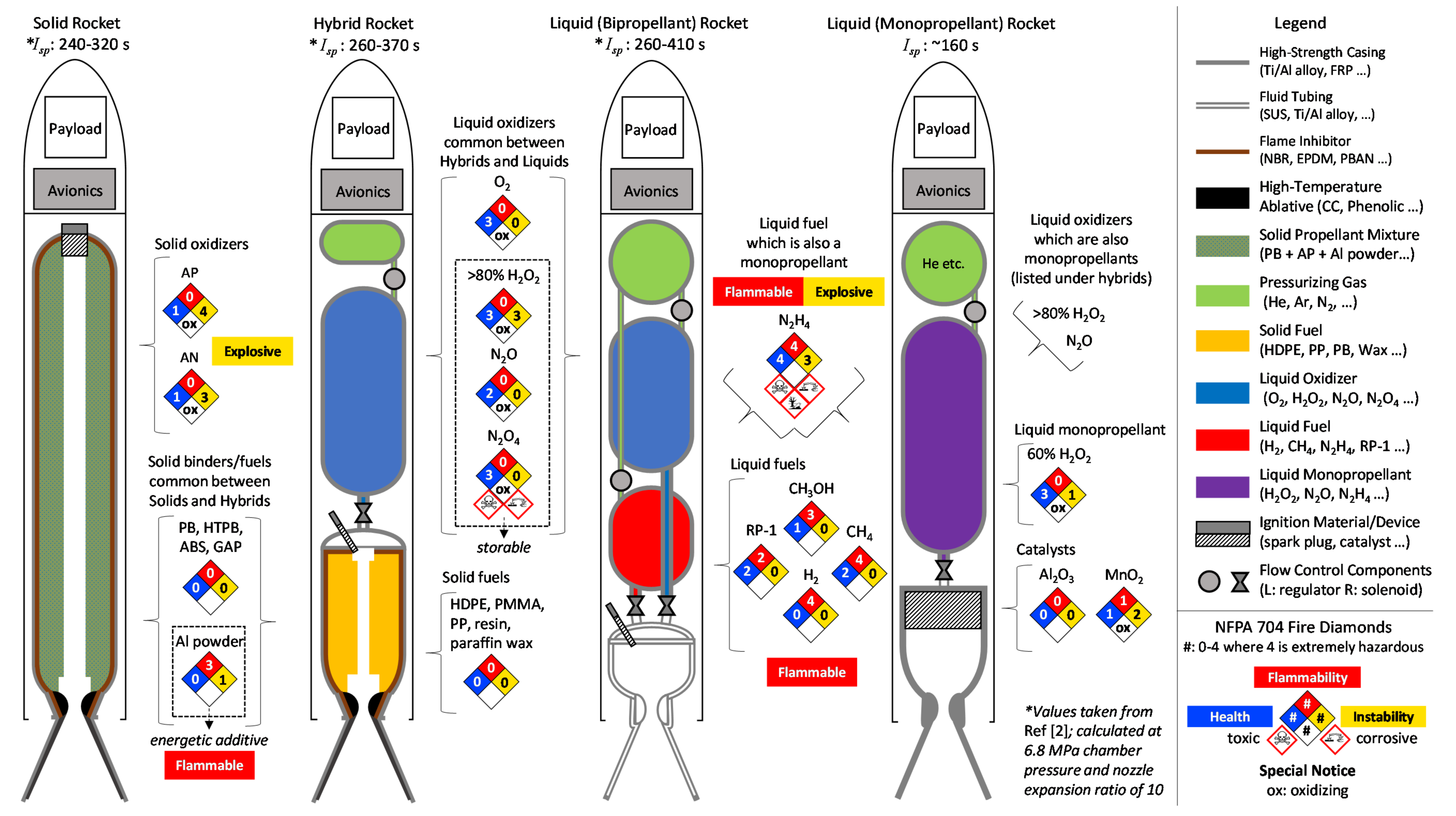
1.1. State of Hybrid Rocket Development

Hybrid rockets are one of the four main chemical rocket configurations conceived during the birth of rocketry, which are: the solid, liquid, and hybrid bipropellant rocket configurations; and the liquid monopropellant rocket configuration. These configurations are distinguished by the storage phase and position of the fuel and oxidizer prior to operation. In the hybrid rocket, the fuel and oxidizer are stored in separate phases. Typically, the fuel is a solid stored within the thrust chamber, and the oxidizer is a liquid supplied to the thrust chamber during operation. The hybrid rocket configuration is attractive because most liquid oxidizers and solid fuels are inherently non-flammable and non-explosive, as is evidenced by the fire diamonds listed in Appendix A.
Nearly 70 years of hybrid rocket research and development took place in the 20th century, but this progress was made on the sidelines of an industry heavily focused on solid and liquid rocket development. The totality of 20th century research and development results sufficiently demonstrate that hybrid rockets can achieve ballistic performance that is on par with their solid and liquid rocket counterparts, however, during this period, hybrid rockets failed to reach the same technological maturity level or market prominence. For example, there are hundreds of technical reports documenting successful hybrid rocket combustion experiments which achieve a specific impulse and density-specific impulse, roughly on the average of the values of solid and liquid rockets. However, there are only a few successful hybrid rocket launches that reached beyond the Karman line, and no public demonstrations of orbital insertions or in-space maneuvers. Readers who are interested in learning about this era of technological development should turn to the landmark publication(s) by Kuo and Chiaverini for further details [1,2,3].
Fortunately for the hybrid rocket developers of the 21st century, the appeal of an inherently non-flammable and non-explosive chemical rocket has become an even more attractive selling point for those interested in developing the emerging commercial space market. A prominent example was made around the turn of the century, when Mojave Aerospace Ventures was awarded the Ansari X prize for building and launching a spacecraft capable of carrying three people to 100 km above the Earth’s surface, twice within two weeks [4]. SpaceShipOne, the spaceplane that achieved these groundbreaking space flights, was powered by a hybrid rocket built by the companies SpaceDev and Scaled Composites. SpaceShipTwo, the successor to SpaceShipOne, is now nearing its commercial debut as the world’s premier suborbital spaceplane under the parent company Virgin Galactic.
Since the maiden flight of SpaceShipOne, hybrid rockets have become the core technology of at least seven Earth-launch vehicle developers: Rocket Crafters/Vaya Space (since 2010, USA [5,6]), Gilmour Space Technologies (since 2012, Australia [7,8]), TiSPACE (since 2016, Taiwan [9,10]), Nammo (Nucleus project since 2017 [8,11]), HyImpulse (since 2018, Germany [12,13]), Firehawk (since 2018, USA [5,14]), and SpaceForest (SIR project since 2018, Poland [15,16]); at least four new satellite thruster developers: T4i (since 2014, Italy [17]), Utah State University (since 2014, USA [18,19]), NASA (Kick Motor project since 2016, USA [20,21]), and Hokkaido University (Kick Motor project since 2017, Japan [22,23]); and at least one planetary ascent vehicle developer: NASA (MAV project since 2016, USA [24,25]). In recent years, the Hokkaido University kick motor has become the focus for the authors’ work.

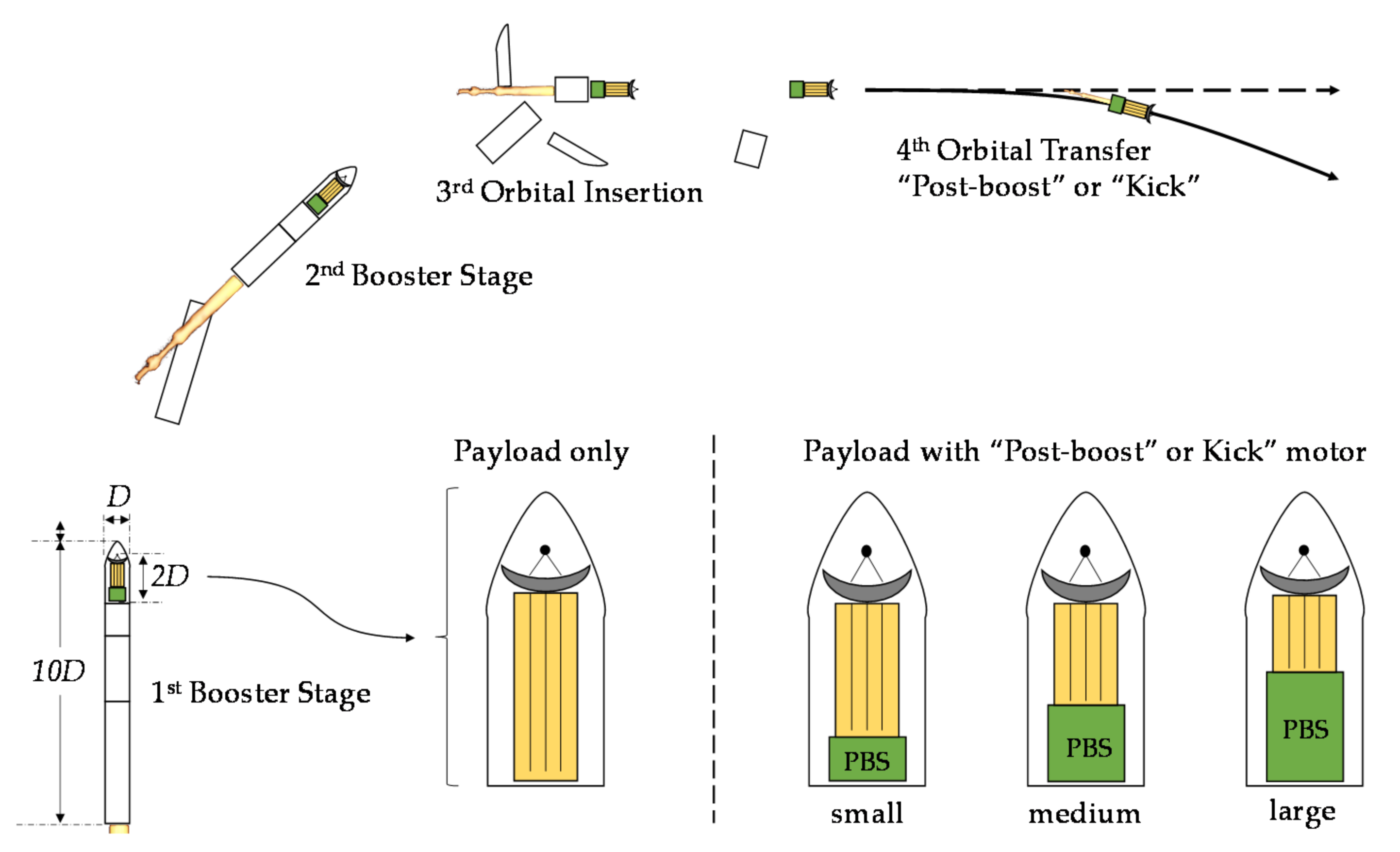
1.2. Post-Boost Stages and Kick Motors

The underlying concept of this paper is that hybrid rocket propulsion should be evaluated for use in post-boost stages and kick motors, which make up a distinct category of propulsion systems, defined here as: propulsion systems which are used to accelerate a payload already in space, and are integrated into a mission at the expense of a launch vehicles existing payload capacity. A depiction of this definition is shown in Figure 1, such that the post-boost or kick can be counted as a “4th stage.” One key difference between launch vehicle stages and post-boost stages or kick motors is the thrust-to-weight requirement. Launch vehicle stages must produce enough thrust to create a net positive acceleration against gravity, whereas post-boost stages and kick motors do not. Another important difference is the envelope shape, i.e., space allocated for mounting the propulsion system. Since the post-boost stage or kick motor shares the payload compartment with the satellite that it is being used to accelerate, a larger post-boost stage or kick motor mass/volume comes at the expense of the payload mass/volume. Other considerations which are particularly important for post-boost stages and kick motors are: the requirement for ignition in low pressure conditions, and the necessity for multiple such ignitions; duration of oxidizer storage, active cooling of the nozzle; integration with reaction control, thrust vector control, and attitude control thrusters; and minimization of solid particle debris.

1.3. Considerations for Hybrid Rocket-Based Post-Boost Stages and Kick Motors

The differing requirements and operating conditions of post-boost stages or kick motors and the launch rockets that bring them to space demand large shifts in research and development priorities. Perhaps the most surprising and counterintuitive example is regarding the efforts to improve solid fuel regression rates in hybrid rockets. Countless hybrid rocket research has been, and continues to be, centered around increasing solid fuel regression rate with the aim of increasing thrust-to-weight ratio. This is the underlying motivation for the use of liquifying fuels, vortex generators, and energetic fuel additives. However, post-boost stages and kick motors, which cannot be guided aerodynamically, may be better off with low and/or less-intense thrust and vortex-free exhaust gas. Moreover, liquifying fuels and fuel additives increase the risk of space debris pollution, which is a major concern of the space industry [26,27]. From this vantage point, slow-burning and pyrolyzing fuels are best suited for producing steady, reliable acceleration, which has a low risk of forming solid particle (space) debris in post-boost stages and kick motors. The other major counterintuitive points, which are related to the impact of dry mass, i.e., non-propellant mass and Isp losses on change in velocity ΔV, are the focus of this research.
This article aims to critically review the design and application of hybrid rocket propulsion systems for use as post-boost stages, or as kick motors, by filling in the information gaps that remain in open literature, mainly: How well can hybrid rockets be expected to perform in low height-to-diameter envelopes? How significantly do O/F shift and nozzle erosion affect ΔV capability? Which of the common hybrid rocket oxidizers performs best? Finally, how significantly do pressurizing feed systems increase dry mass? These questions are answered by modeling both the mass of the hybrid rocket based on the configuration within a specified envelope, as well as the time-varying specific impulse based on internal ballistics calculations for propellant consumption rate and nozzle throat erosion rate.

2. Materials and Methods

The systematic evaluation of ΔV capability of hybrid rocket-based post-boost stages in this paper aims to incorporate realistic estimations of the key terms of the governing equation of ΔV: propellant mass, Mpropellant; total wet mass, Mwet; and (effective) time-averaged specific impulse Isp (see Equation (1)). This is done by carefully framing the problem at hand. First, the governing equation of ΔV is re-examined to highlight the key concerns of the post-boost stage and kick motor design in context. Next, as is the case for actual post-boost stages and kick motors, the envelope is defined. Then, a representative set of oxidizers are selected for comparison of theoretical Isp, and the effect of motor configuration on maximizing Isp. Note that hybrid rocket fuels have relatively little effect on theoretical Isp, and for this reason high-density polyethylene (HDPE) is chosen as the fuel material throughout. Next, to allow for a realistic estimation of masses, a standardized formulation for all key components of the motor is made. Regarding the estimation of time-varying Isp, this requires the simulation of internal ballistics in time, including the effects of O/F shift and nozzle throat erosion, which is accomplished by creating a new computational algorithm. Each of these steps are explained in detail through framing the problem in the following subsections.

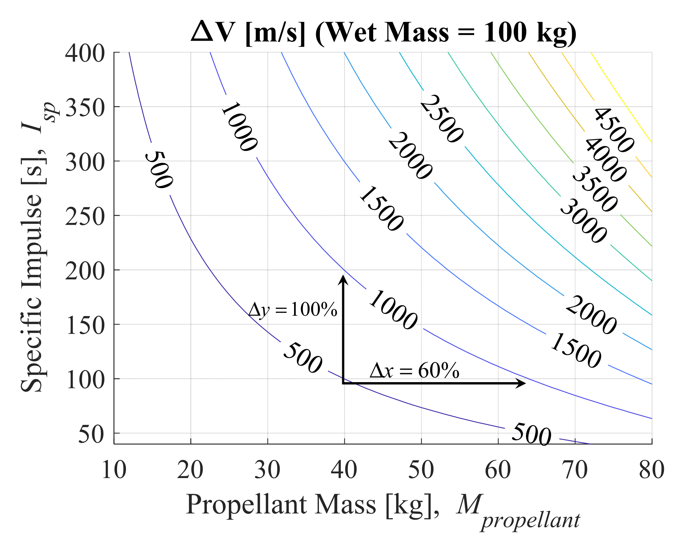
2.1. Maximizing the Change in Velocity, ΔV

The main design objective of any in-orbital rocket, including the post-boost stages and kick motors under consideration in this study, is to achieve a change in velocity, ΔV in m/s. For a rocket where the specific impulse, Isp (in s), is constant, this ΔV can be calculated according to Tsiolkovsky’s rocket equation:
Δ V = g I s p ln M w e t / M w e t M p r o p e l l a n t ,
where g is gravitational acceleration (≈9.8 m/s2), Mwet is wet mass in kg, and Mpropellant is propellant mass in kg. Based on the definition for post-boost stages and kick motors in Section 1.2, the Mwet is a constraint of the launch vehicle, and thus Equation (1) can be considered predominately a function of Isp and Mpropellant, as shown by the contours in Figure 2. For the purposes of demonstrating the sensitivities of ΔV to Isp and Mpropellant, Mwet has been defined for convenience to be 100 kg. Thus, the values of Mpropellant shown as the abscissa in kg, can also be interpreted as percentages of Mwet—i.e., propellant mass fractions. The two key takeaways from Figure 2 are that: (1) both increasing the Isp and Mpropellant of the propulsion system greatly improves ΔV; and (2) that increasing the propellant mass has an even greater impact on ΔV than increasing the Isp. The latter point will be the explanation for some of the surprising, or counterintuitive results of this paper. Note that this takeaway is obvious from Equation (1), since ΔV is linearly proportional to Isp, while Mpropellant is in the denominator of the logarithm term. However, the non-linearity of the sensitivity to Mpropellant is difficult to intuit, and combined with lack of a standardized mass formulation makes quantitative comparisons of propulsion systems regarding Mpropellant challenging. Lastly, Isp is changing in time in most hybrid rockets, due to a mixture ratio shift, typically referred to as “O/F shift.” Accordingly, the analysis in this paper will consider the effect of both terms when evaluating performance (potential).

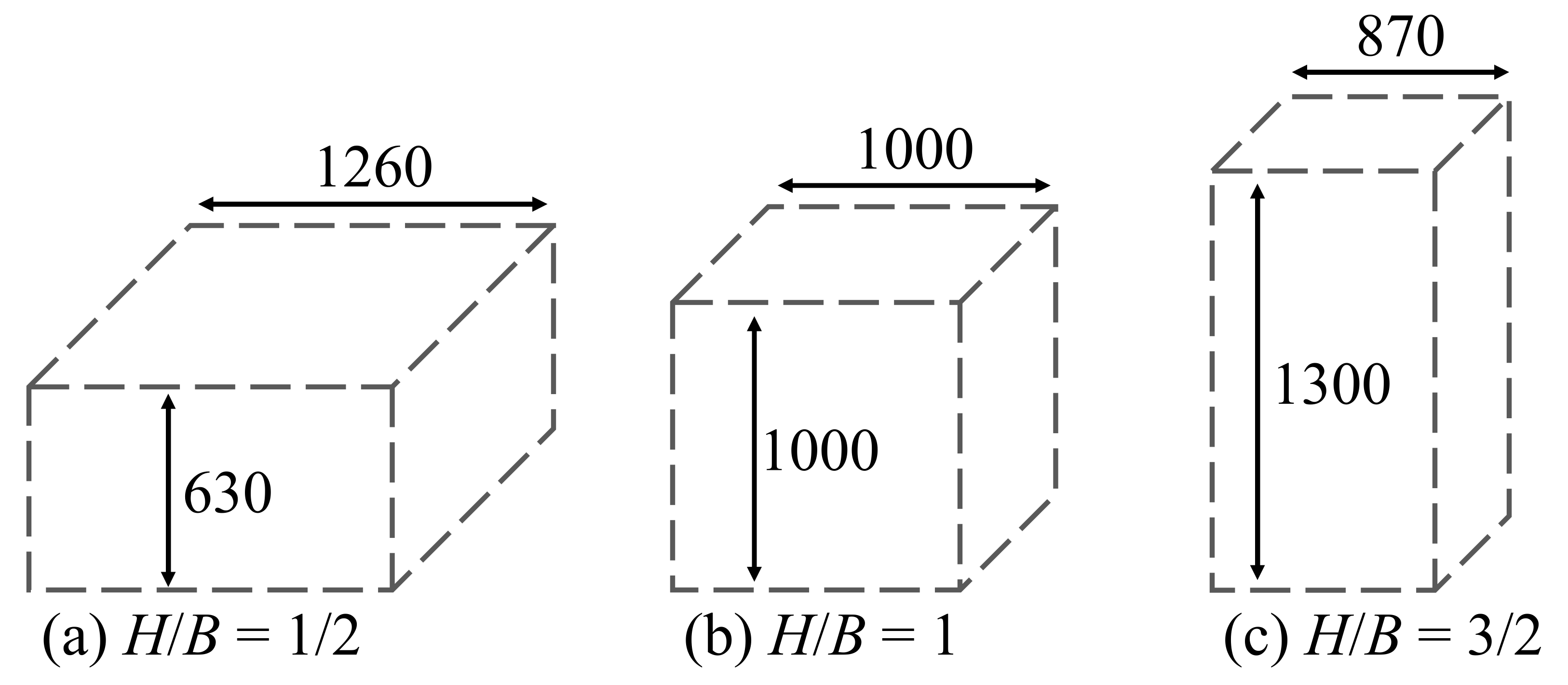
2.2. The Envelopes and Their Parametrization

Since the height-to-base ratio, H/B, of the motor envelope will affect the shape of the thrust chamber, ultimately affecting the shape of the fuel stored inside the thrust chamber, this term was chosen to be the independent variable of the envelope shape. Moreover, this parameter also relates to the relative size of the post-boost stage or kick motor with regards to the satellite it is accelerating, as depicted by the “small, medium, and large” cases in Figure 1. By comparing the performance of similar motors under varying envelope shapes, it will be shown whether a given motor is higher-performing as a short and flat motor or tall and skinny motor. Moreover, since there is also reason to believe that variations in total volume may also affect the performance, volume is controlled as a dependent variable. For convenience, the authors have set this volume to be one cubic meter. The resulting envelopes, each one cubic meter in volume, are depicted in Figure 3. Note that although the envelope volume was arbitrarily defined for convenience to be one cubic meter, the resulting envelopes fit surprisingly well with many of the existing small to medium-launch vehicle payload compartments, meaning that the motors presented in this paper will serve as a valuable reference for actual post-boost stages.

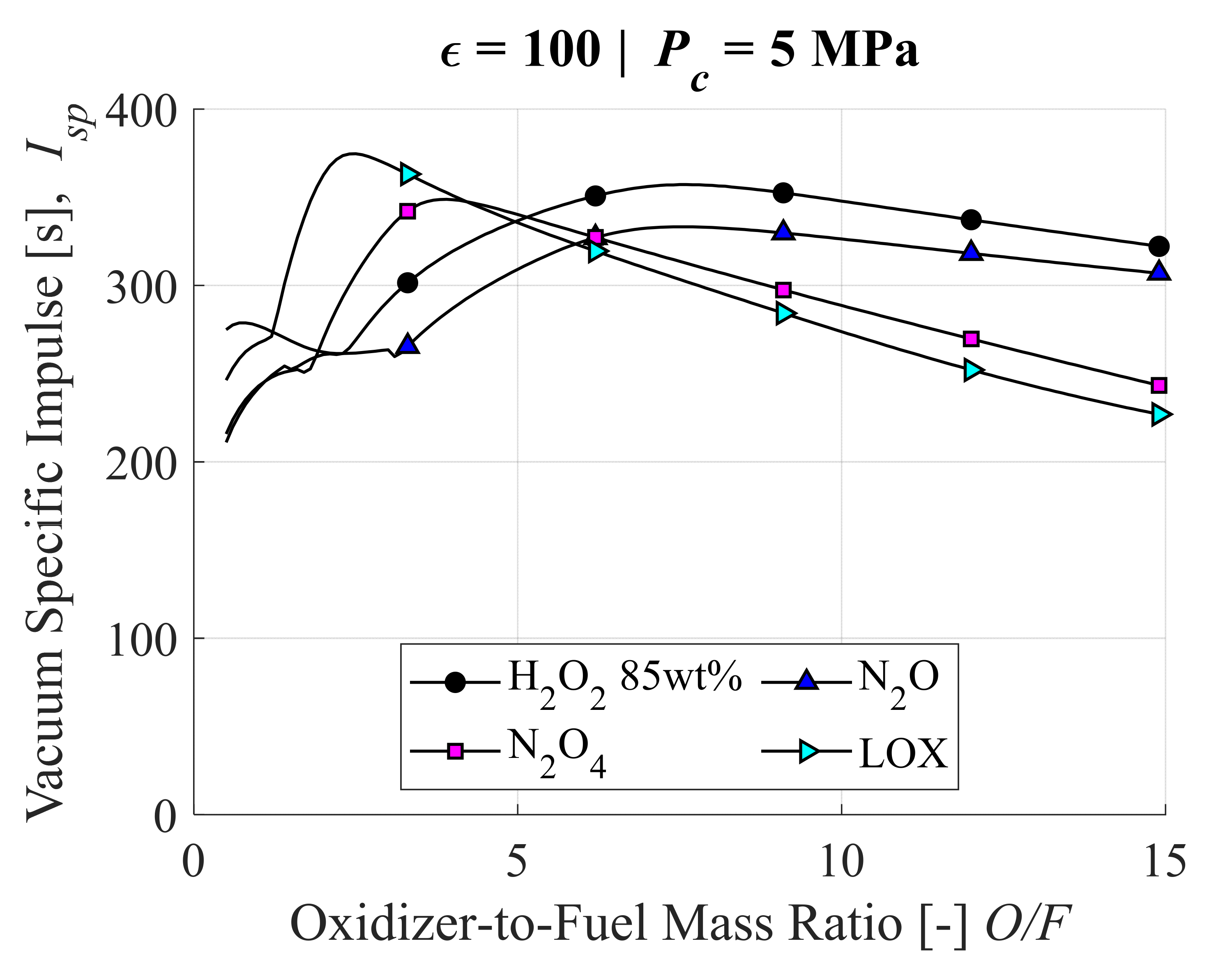
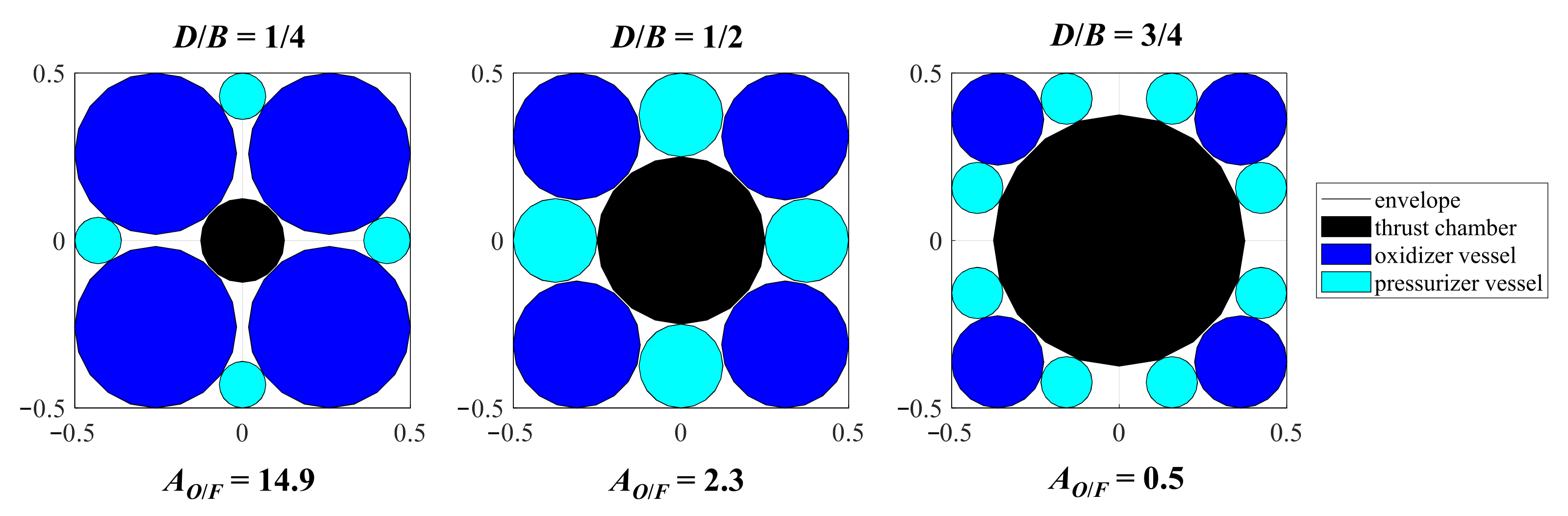
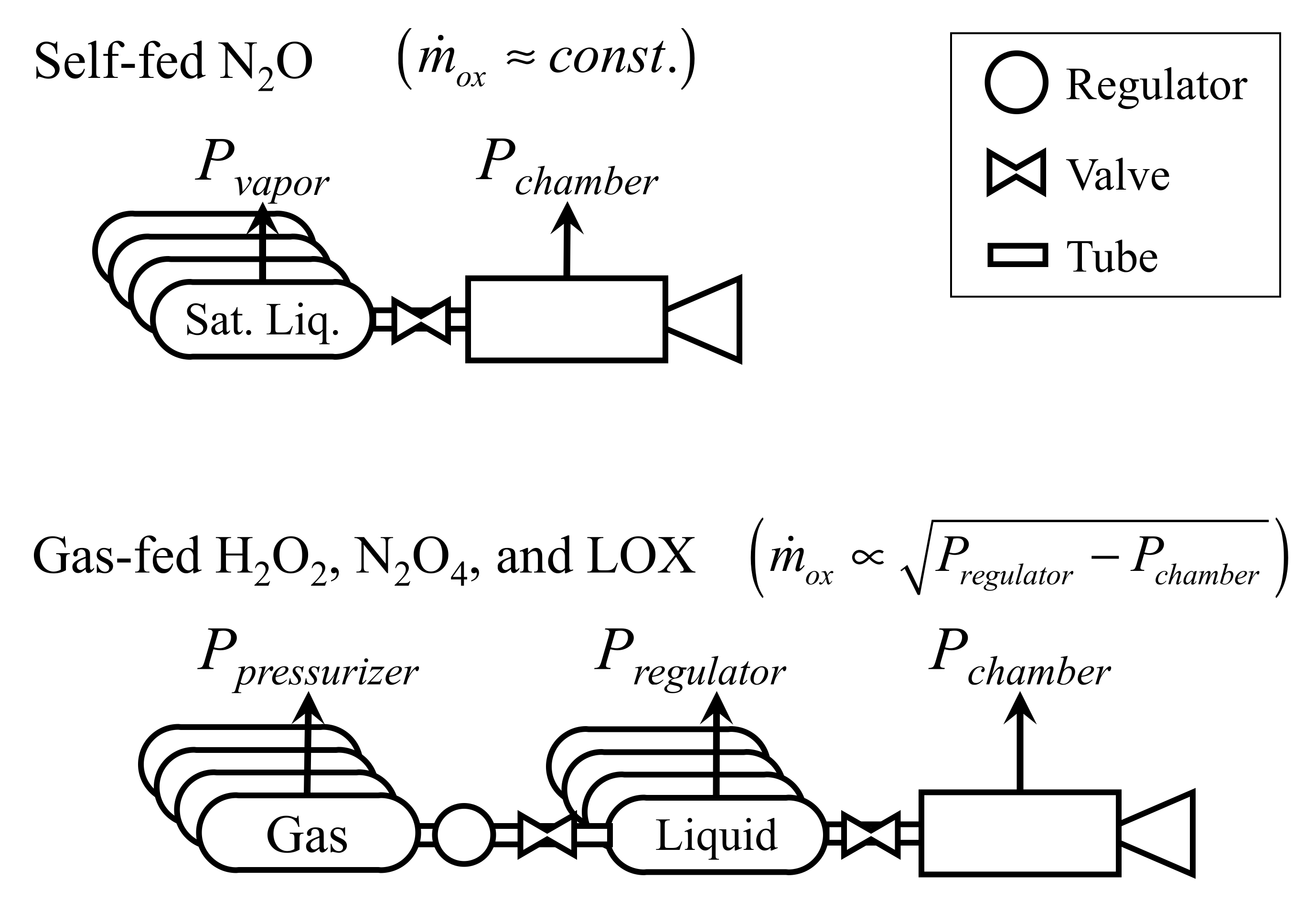
2.3. The Oxidizers, Their Theoretical Isp, and Effect on Motor Configuration

Four common hybrid rocket oxidizers are considered for this analysis: 85 wt% hydrogen peroxide (H2O2); nitrous oxide (N2O); dinitrogen tetroxide (N2O4); and (liquid) oxygen (LOX). Most previous research, both theoretical and experimental, has been carried out using one of these oxidizers, or a close cousin of these oxidizers. A summary of the basic properties of these oxidizers is listed in Table 1. The theoretical vacuum Isp dependencies on O/F are shown by the plots in Figure 4. These oxidizers are diversified in terms of density and specific impulse, which makes them appropriate for comparison of ΔV performance. High-density and high-specific impulse are expected to lead to high-performance, and vice versa. Some other important considerations which relate to cost, handling, and feasibility for use in a space environment have been listed as either positive or negative in Table 1.
There are three key takeaways from Table 1 and Figure 4, which hint at the most important tradeoffs between oxidizers in terms of maximizing ΔV. The first is that the variation in maximum Isp between oxidizers, 333 s for N2O to 357 s for LOX, or ±4% of the median, is much less than the variation in density, 550 kg/m3 for N2O to 1440 kg/m3 for N2O4, or ±80% of the median. Thus, these variations in storage density, which affect storage vessel size and mass, will have a greater impact on ΔV than variations of Isp. Secondly, the sensitivity of maximum Isp to O/F is greater for LOX than the other oxidizers. This means that although the LOX system has the greatest Isp potential, it is uniquely vulnerable to performance losses due to O/F shift. Lastly, the location of optimum O/F will determine the appropriate proportion of fuel mass, which means the appropriate allocation of volume to the thrust chamber. Since the optimum O/F of LOX is one-third that of N2O or H2O2 85 wt% (2.5 versus 7.5), the thrust chamber will be larger in size, while the oxidizer pressure vessels will be smaller. Thus, if the mass per unit volume of the thrust chamber is larger than the oxidizer vessels, the non-propellant mass of the system will be larger and ΔV smaller. It will be shown in the following sections that this is in fact the case.
Figure 5 graphically depicts the consequence of thrust chamber size on the remaining space available for the oxidizer and pressurizer storage, given the motor envelope profile is square, and the circular cross sections for oxidizer vessels and pressurizer vessels are selected for maximum area, in that order. Here, the parameter listed as D/B is the ratio of thrust chamber diameter to the base dimension of the square envelope. The term AO/F is the ratio of the cross-sectional area available for oxidizer vessels to that available for the thrust chamber (containing the fuel). Granted that the area ratio does not translate directly to propellant mass ratio, it is a primary factor. Other factors include the height of the vessels, and the densities of the propellants. For example, referring to the optimum O/F of the LOX case as an example, i.e., 2.5, and if the fuel and oxidizer have similar densities, we can expect the optimum motor configuration to be closer to the middle of Figure 5, when D/B = 1/2, which results in an AO/F = 2.3. Another insight from Figure 5 regarding the design of motors which require pressurizer gas is that larger oxidizer vessels lead to smaller pressurizer vessels. Either a larger volume or greater pressure of pressurizer gas is necessary for a larger oxidizer vessel volume. Thus, for the post-boost/kick motor configuration in which oxidizer vessel volume comes at the expense of pressurizer gas volume, increasing the pressurizer pressure is the only way to satisfy the requirements for pressure-fed systems.

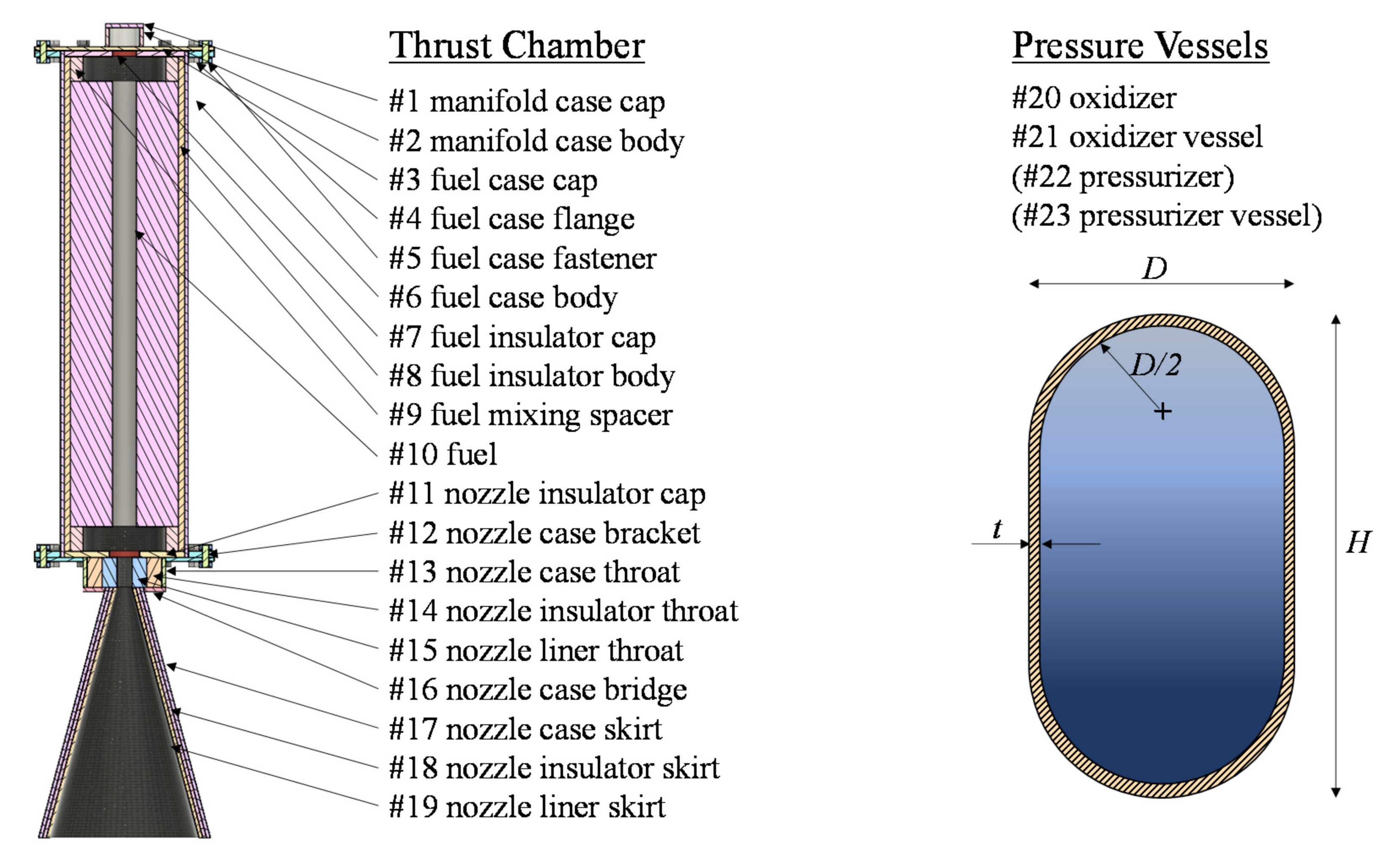
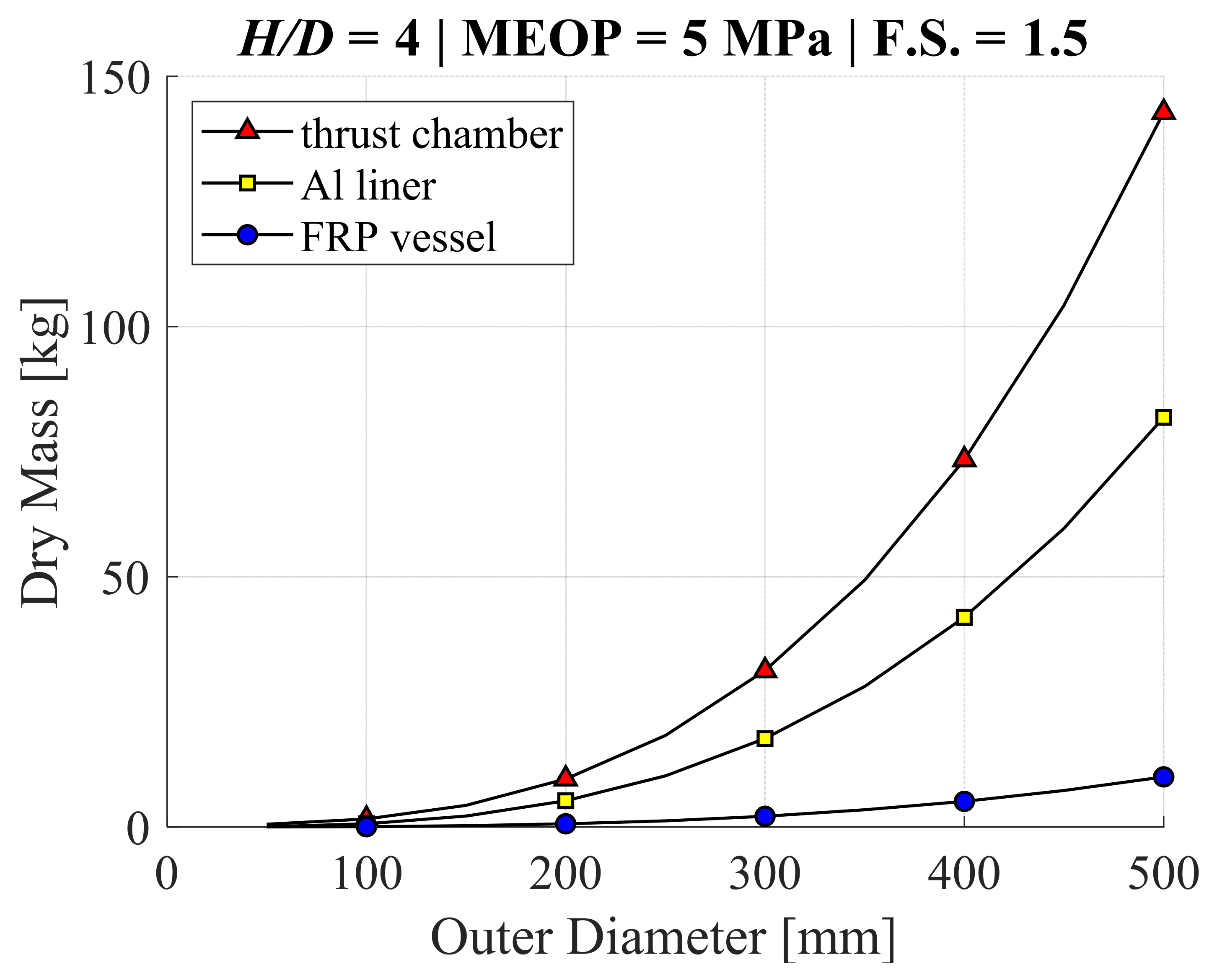
2.4. Standardized Formulation of Motor Component Size and Mass

One key contribution of this research is the standardization of motor components for a realistic estimation of motor mass, and propellant mass fraction. In Section 2.1 it was shown that propellant mass fraction has the greatest impact on ΔV. In Section 2.2 it was shown that different hybrid rocket oxidizers require different O/F, and that the density of the oxidizers varies greatly. Thus, the motor mass and size will vary greatly for each oxidizer, and it is not obvious which system will result in the greatest ΔV. What is important for comparison purposes is that the aspect ratios, densities, and material strengths of each component are fixed, so that even as the size and configuration of various motors are investigated, the formulation of mass is consistent.
Figure 6 shows a breakdown of components of the thrust chamber, and pressure vessel designs defined for the purposes of standardization. The thrust chamber design, comprised of 19 subcomponents, is based loosely on actual thrust chambers used in previous research by the authors. We are confident that this thrust chamber would function satisfactorily if produced and assembled exactly as depicted. Furthermore, the production of this thrust chamber is feasible almost anywhere in the world, because no highly advanced manufacturing methods would be required. Consequently, it is not the lightest possible solution for a thrust chamber, and would likely not be competitive in the marketplace. Nonetheless, this design is advanced enough to satisfactorily perform the functions of a post-boost stage or kick motor. It is important to point out that the nozzle skirt, assumed to be conical with a half angle of 15 deg, is located outside of the envelope to prevent this non-idealized design from taking up envelope space. This compromise does not greatly affect the conclusions which can be drawn from this research.
The important point for the purposes of this research is that the thrust chamber and pressure vessels scale with size according to engineering principles, so that the effect of motor size, mass, and configuration on ΔV is captured in a realistic and repeatable manner. The wall thicknesses, t (m), of the case and pressure vessels were determined by Equation (2):
t = F . S . × MEOP × D / 2 × σ y i e l d ,
where F.S. is the factor of safety (=1.5), MEOP is maximum expected operation pressure in Pa, D is the outer diameter of the case or vessel in m, and σyield is yield stress in Pa. The MEOP of the pressure vessels depends on the storage pressure requirements, which is determined for each motor given the volume available for the motor components. However, MEOP for the thrust chambers would require advanced knowledge of maximum chamber pressure during firings, and in this research it needed to be defined in advance of computations. For this reason, it was set at a fixed value of 5 MPa. A summary of material properties assumed for mass estimation are listed in Table 2.
The benefit of standardizing the thrust chamber in this way is evident in the plots in Figure 7, which show the dry masses, i.e., the mass without fuel or oxidizer, as functions of outer diameter—where height-to-diameter ratio H/D = 4, MEOP = 5 MPa, and F.S. = 1.5. The main takeaway is that the dry mass is much larger for the thrust chamber than the pressure vessels. This means that hybrid rocket motors which require relatively large thrust chambers, such as the LOX motor, will have a lower propellant mass fraction than motors which can suffice with smaller thrust chambers. Note that the plot of the “Al liner” in Figure 7 has been added to clarify the reason for this mass disparity, and its theoretical limitations. The Al liner is a vessel with the same shape as the FRP vessel (see right-hand side of Figure 6), but with the density and strength of the thrust chamber case. Thus, even if the thrust chamber insulation, liners, mixing spacers, and nozzle skirt were abandoned, it would never approach the light weight of the pressure vessels, at least not unless a similar FRP construction was used for the thrust chamber as well. Stated another way, to make LOX motors competitive in terms of propellant mass fraction, it is necessary for the thrust chamber to be constructed with FRP, whereas this may not be necessary for the N2O and H2O2 motors which have smaller thrust chambers.
There are a few additional components included in the motor mass estimation, which are more easily explained in conjunction with an overview of the oxidizer supply systems. Two oxidizer supply systems are considered in this research. First is the supply system for N2O. Due to the combination of a low storage density and large optimum O/F, it is best to take advantage of the relatively high vapor pressure as a means for self-feeding to the thrust chamber. The self-fed N2O system is depicted in the upper half of Figure 8. Only one valve is required to control the flow, and no pressure regulation is necessary. The remaining three oxidizers have very low vapor pressures, and are incapable of using the self-fed configuration. Instead, a pressurizer gas, i.e., “pressurizer,” is used to force feed the liquid oxidizer into the thrust chamber. The gas-fed supply system is depicted in the lower half of Figure 8. Since (pressurizer) gas has a much lower density than the liquid (oxidizer), it must be stored at a relatively high pressure, and regulated to the appropriate feed pressure. Thus, two valves and a regulator are required for the gas-fed system. The mass breakdown of these components is shown in Table 3. Due to a lack of open-source information on high-flow rate regulators, the regulator mass is neglected in this research. The tube mass is based on Swagelok 3/4” stainless steel tubing, where tube length is set to the perimeter (i.e., 4B) of the envelope for each pressure vessel set. In other words, for the self-fed N2O system, the tubing length is one envelope perimeter, whereas it is two for the gas-fed systems. The valve mass is extrapolated from Marotta CoRe series valves for the larger tube diameter. The valve mass is double for the LOX downstream valve to act as a penalty for the cryogenic temperature conditions, which the valves are not designed for. Lastly, a structure for holding the components in place and mounting solar panels etc. is considered, such that the frame of gas-fed case is 50% heavier than the self-fed case. This frame is a reference from a recent paper [28], which based this mass estimation on CAD models.

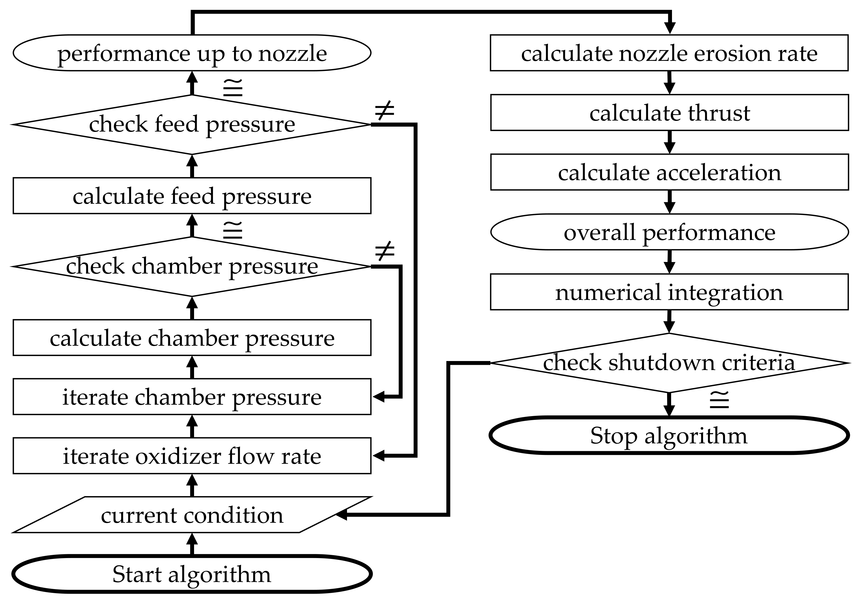
2.5. Internal Ballistics Simulation Algorithm

In hybrid rockets, it is necessary to predict the fuel mass consumption rate which results from boundary layer combustion, as well as the change in chamber pressure and nozzle expansion ratio due to nozzle erosion. Carrying out these calculations may not be straight forward, even when the necessary empirical correlations exist. It is not only due to the fact that governing equations for fuel consumption rate vary greatly for the various types of hybrid rocket designs, but until recently, there was no empirical basis for predicting nozzle erosion. For these reasons, it has been challenging to propose an “all-purpose” algorithm for hybrid rocket performance prediction and comparison.
The algorithm introduced in the paragraphs below was conceived to allow for the prediction and comparison of hybrid rockets of varying oxidizer supply methods, fuel grain designs, and nozzle designs based on the general form of internal ballistics equations, which consistently appear in the latest experimental research. The algorithm is presented in a way which allows for modifications to accommodate the various types of hybrid rockets of interest to the reader. An example of a specific performance comparison based on this algorithm can be found in reference [22].
The general principle of the algorithm is to use the characteristic exhaust velocity equation, chemical equilibrium equations, and fluid mechanical equations in the feed lines to determine the oxidizer mass flow rate and chamber pressure prior to estimating the conditions in the nozzle and thrust produced by gas expansion through the nozzle. Depending on the hybrid rocket system being evaluated, multiple iterative calculations may be required to determine oxidizer mass flow rate, fuel mass flow rate, and the pressure cascade between the oxidizer vessel and the chamber. This is because these terms are often interdependent and non-linear in nature. A flow chart of the algorithm is shown in Figure 9. It is necessary to enter the algorithm with several initial conditions, which include but are not limited to: initial masses, volumes, pressures and temperatures of oxidizer, fuel and pressuring gas when used; flow coefficients of the oxidizer supply line and injector; the oxidizer injection geometry; the fuel port geometry and configuration; the nozzle throat diameter, exit diameter and contour is some cases; and atmospheric conditions. Within the body of the algorithm mass flow rates, surface regression rates and acceleration are determined, and integrated in time through numerical integration.
Given the values of the initial nozzle throat area At [m2], fuel port radius rfu [m], fuel density ρfu [kg/m3], burning surface area Abs [m2], and an educated guess for oxidizer mass flow rate m ˙ o x [kg/s], the fuel mass consumption rate m ˙ f u [kg/s], chamber pressure Pc [Pa], and characteristic exhaust velocity c* [m/s], can be determined by the system of Equations (3)–(5):
P c = c * m ˙ o x + m ˙ f u / A t ,
c * = f m ˙ f u , m ˙ o x , P c f NASA   CEA ,
m ˙ f u = f A b s , m ˙ o x , P c , r f u , ρ f u   f a A b s ρ f u P c m m ˙ o x / π r f u 2 n ,
Here, Equation (3) is the characteristic exhaust velocity equation rearranged for chamber pressure. Equation (4) is representative of the chemical equilibrium calculations that result in a theoretical value for characteristic exhaust velocity. For example, the NASA CEA software suite can serve as function “f” of Equation (4) [29]. Equation (5) is representative of the range of possible fuel mass consumption rates that result from empirical correlations for fuel regression rate and corresponding fuel geometries. The dependent terms of Equation (5) have been deliberately left incomplete to express the fact that these functional dependencies depend on the type of hybrid rocket design employed. However, the f provided adjacent to the equation is the form used in this research—see Table 4 for values of empirical constants. The key takeaway from this system of equations is that they are non-linearly interdependent, and in most cases must be solved using an iterative technique.
Given the value of chamber pressure, oxidizer phase and corresponding flow coefficients, and cross-sectional areas of the supply line, CD [-] and AD [m2], the pressure cascade can be determined according to the functional dependencies listed as Equation (6) or related fluid mechanical correlations.
( a )   incompressible :   m ˙ = C D A D 2 ρ Δ P u p , d w ( b )   compressible :   m ˙ = C D A D 2 ρ u p P u p γ γ 1 P d w P u p 2 γ P d w P u p γ + 1 γ ( c )   choked :   m ˙ = C D A D 2 ρ u p P u p 2 γ γ + 1 γ + 1 γ 1 ( d )   flashing :   m ˙ = C G A D
Here, the furthest downstream pressure denoted by the subscript “dw”, is the chamber pressure, for which the upstream pressure denoted by the subscript “up,” is the injector inlet pressure. Note that an iterative technique is necessary for calculating the upstream pressure of a compressible flow based on the downstream pressure. Since the furthest upstream pressure is set by the designer, this value can serve as a reference point for adjusting the oxidizer mass flow rate iteration. The system of Equations (3)–(6) are closed when the supply pressure resulting from the guess for oxidizer mass flow rate matches the value set by the designer.
Once the chamber pressure and combustion gas properties have been determined, the heat transfer to the nozzle throat can be estimated using numerical methods, however this modeling of transient heating at the throat is intensive, depends significantly on the geometry and materials used, and is not unique to this algorithm. There is no satisfactory generalization of the equations necessary for heat transfer modeling, and thus for the sake of continuing the nozzle erosion rate calculations, a constant nozzle throat wall temperature will be assumed. Here, the intent of the authors is to assume a nozzle wall temperature that will lead to relatively high erosion rates for the given conditions at the throat, however not unrealistically high as to defy precedent from previous research. Although the uncertainty in throat wall temperatures of previous research—see [30,31]—is relatively large, estimations for nozzle throat wall temperatures, even in the most severe cases of nozzle throat erosion, approach a steady state near 80% of the adiabatic flame temperature of combustion gas in the thrust chamber, Tc. Accordingly, it will be assumed that nozzle wall temperature Tw [K], is 80% of the chamber pressure Tc, which can be output from NASA CEA simultaneously with c* as done in Equation (4). This assumption will result in an exaggeration of the nozzle erosion rates because according to [30,31], nozzle erosion does not begin until the surface reaches temperatures around 1500 K to 2000 K, and it takes a non-negligible amount of time for the nozzle (throat) surface to reach and surpass these temperatures. However, the exaggerated effect of nozzle erosion on motor performance is acceptable for the sake of understanding the impact on ΔV.
The generalized form of the function for determining nozzle erosion rate, r ˙ n [m/s], is listed as Equation (7)
r ˙ n = β 1 Φ β 2 T w b P n exp β 3 Φ + E / T w ρ w ρ n Re 0.83 Sc CO 0.44 D CO , w d ,
where dn (m) is nozzle (inner) diameter, DCO,w [m2/s] is the binary mass diffusivity of CO in air calculated at the nozzle wall temperature, P (Pa) is (local) pressure, Re (-) is Reynolds number, ScCO (-) is the Schmidt number of CO as calculated at the nozzle wall temperature, Φ (-) is the equivalence ratio of combustion gas, ρn (kg/m3) is nozzle material density, and ρw is the density of combustion gas calculated at the wall temperature (kg/m3). Note that this equation was only recent proposed, and before there was no correlation which included a nozzle temperature term. Currently, the empirical constants β1,2,3, b and n, as listed in the example formula of Equation (7), have only been determined for graphite nozzle erosion under the use of oxygen [30] and nitrous oxide [31]. The empirical constants of Equations (5) and (7) as they pertain to this research are summarized in Table 4.
At the same stage in the algorithm, all the terms necessary for determining thrust are available, according to the set of Equations (8) and (9):
P e = f A e , A t , P c , γ   P e P c 1 γ γ + 1 γ 1 1 P e P c γ 1 γ = A t A e γ + 1 2 1 1 γ ,
F = m ˙ o x + m ˙ f u c * 2 γ 2 γ 1 2 γ + 1 γ + 1 γ 1 1 P e P c γ 1 γ + P e P a A e ,
Here, the nozzle throat and exit areas, At and Ae [m2], are defined within the initial conditions at the start of the algorithm, whereas m ˙ o x , m ˙ f u , and Pc are determined by calculations completed earlier in the algorithm. NASA CEA or a similar chemical equilibrium solver is necessary for determining the specific heat ratio of combustion gas, γ, but it is worth mentioning that NASA CEA can be used to carry out Equations (8) and (9) as well.
The next section of the algorithm is to numerically integrate mass flow/consumption rates, regression and erosion rates, and acceleration to determine the remaining propellant mass and feed pressure, fuel and nozzle geometry, and overall change in velocity. In the self-fed N2O motor, whether liquid N2O remains and how much remains, is determined by treating the oxidizer vessel as a control volume and tracking the total enthalpy of this control volume. Here, the enthalpy values are a reference from the NIST online database, and are obtained by using the equilibrium method outlined in reference [34]. After liquid N2O has been depleted, the remaining gas N2O is supplied to the thrust chamber similar to a gas blowdown feed system.
The final section of the algorithm is to determine whether the rocket must be shut down or not. Simulations in this research are shut down when one of the following is true: (1) the fuel is depleted; (2) the oxidizer is depleted; (3) the chamber pressure falls below 1 atm; (4) the nozzle throat is consumed.

3. Results

The results are presented in two parts. The first part compares the ΔV of the post-boost stage/kick motors using the four oxidizers—i.e., H2O2 85 wt%, N2O, N2O4, and LOX—under the assumption that O/F and At are constant during combustion. This means that the algorithm in Section 2.5 is unnecessary, and ΔV can be determined according to Equation (1) alone. The second part focuses on the two highest performing cases to investigate to what degree O/F shift and nozzle throat erosion are likely to degrade ΔV. In both parts, the independent variable is the ratio of thrust chamber diameter to envelope base, D/B, which also determines the space available within the envelope for the oxidizer vessels, and in turn the pressurizer vessels for the gas-fed motors. Moreover, ΔV is calculated based only on the masses of the thrust chamber, oxidizer supply system, and structure as outlined in Section 2.4. For this reason, the results of ΔV are larger than should be expected in practice, which would include the additional non-propellant masses of the payload, bus etc.

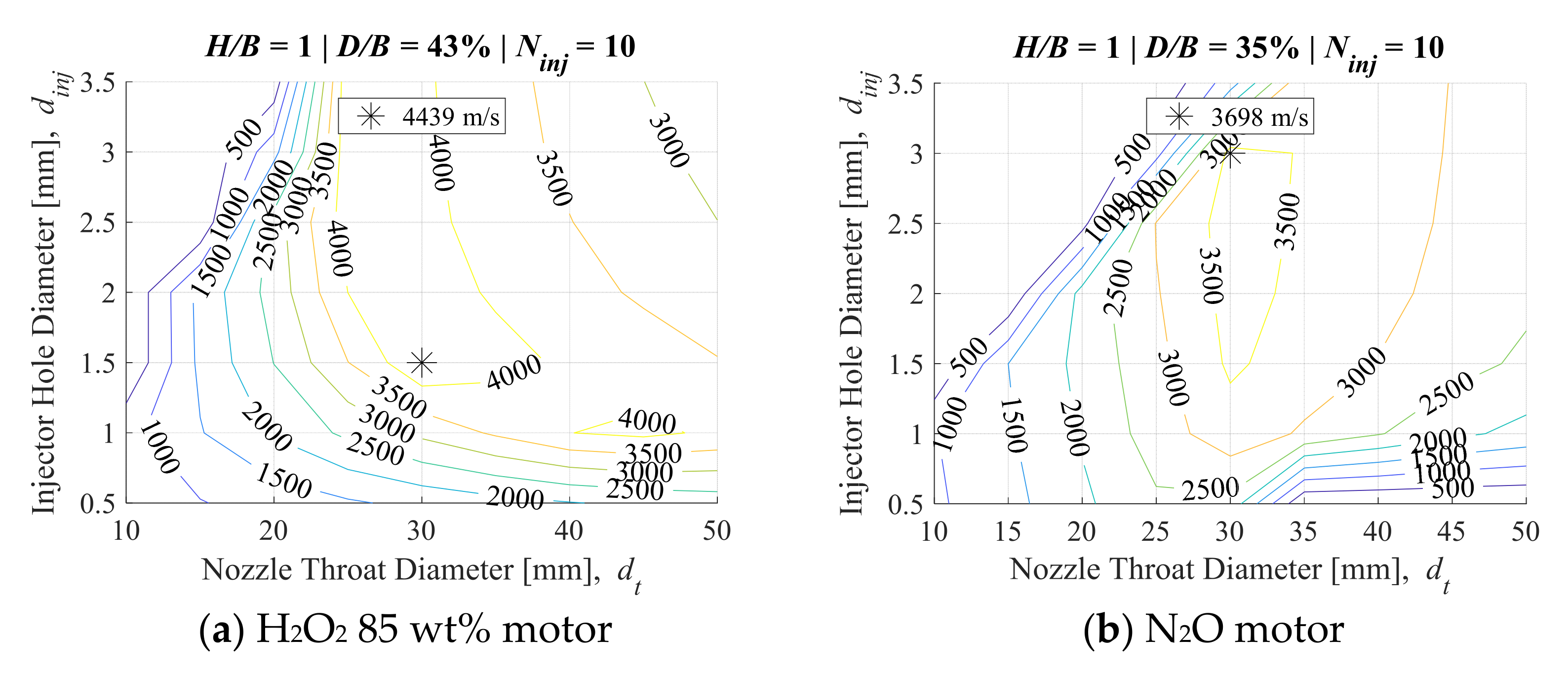
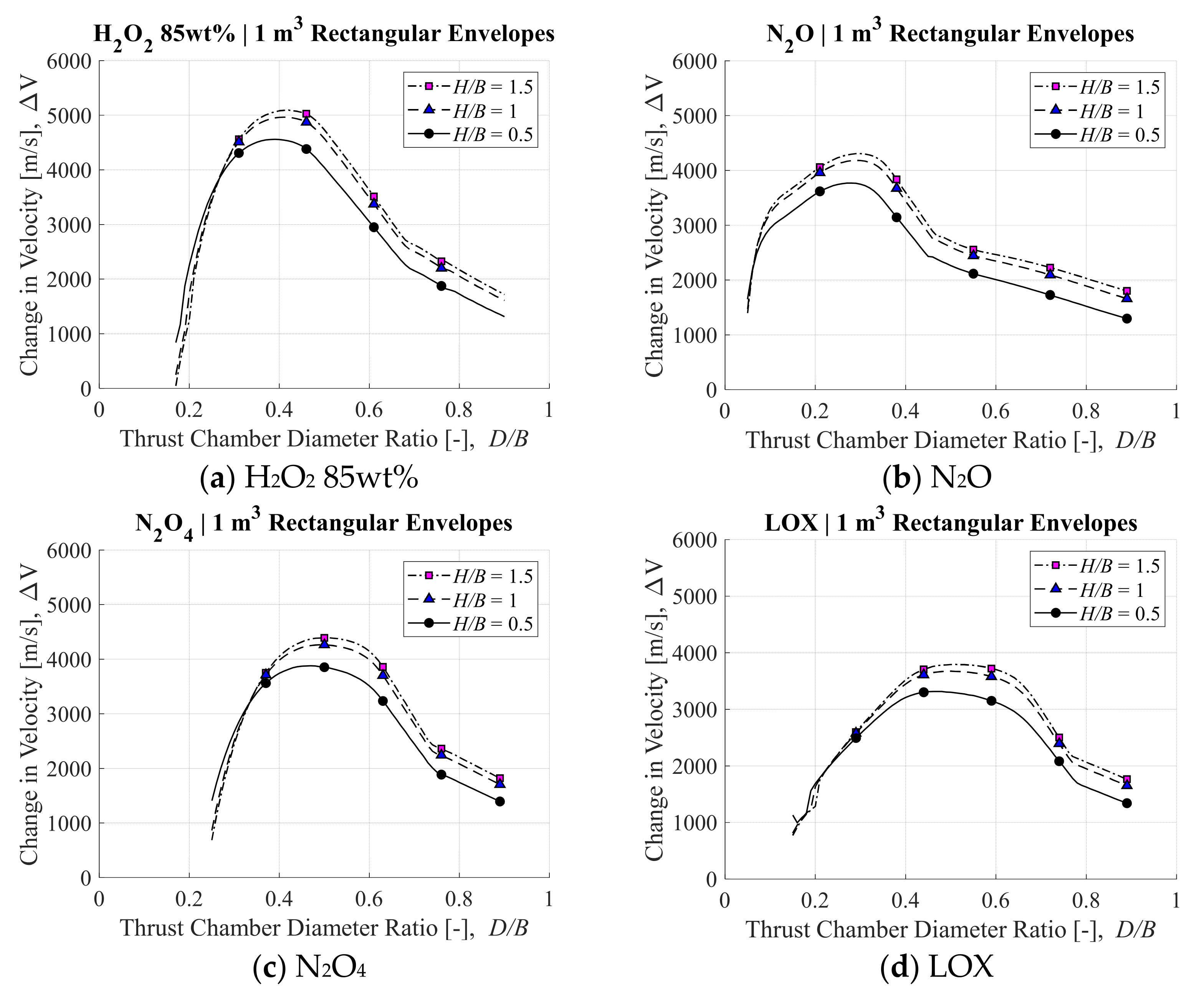
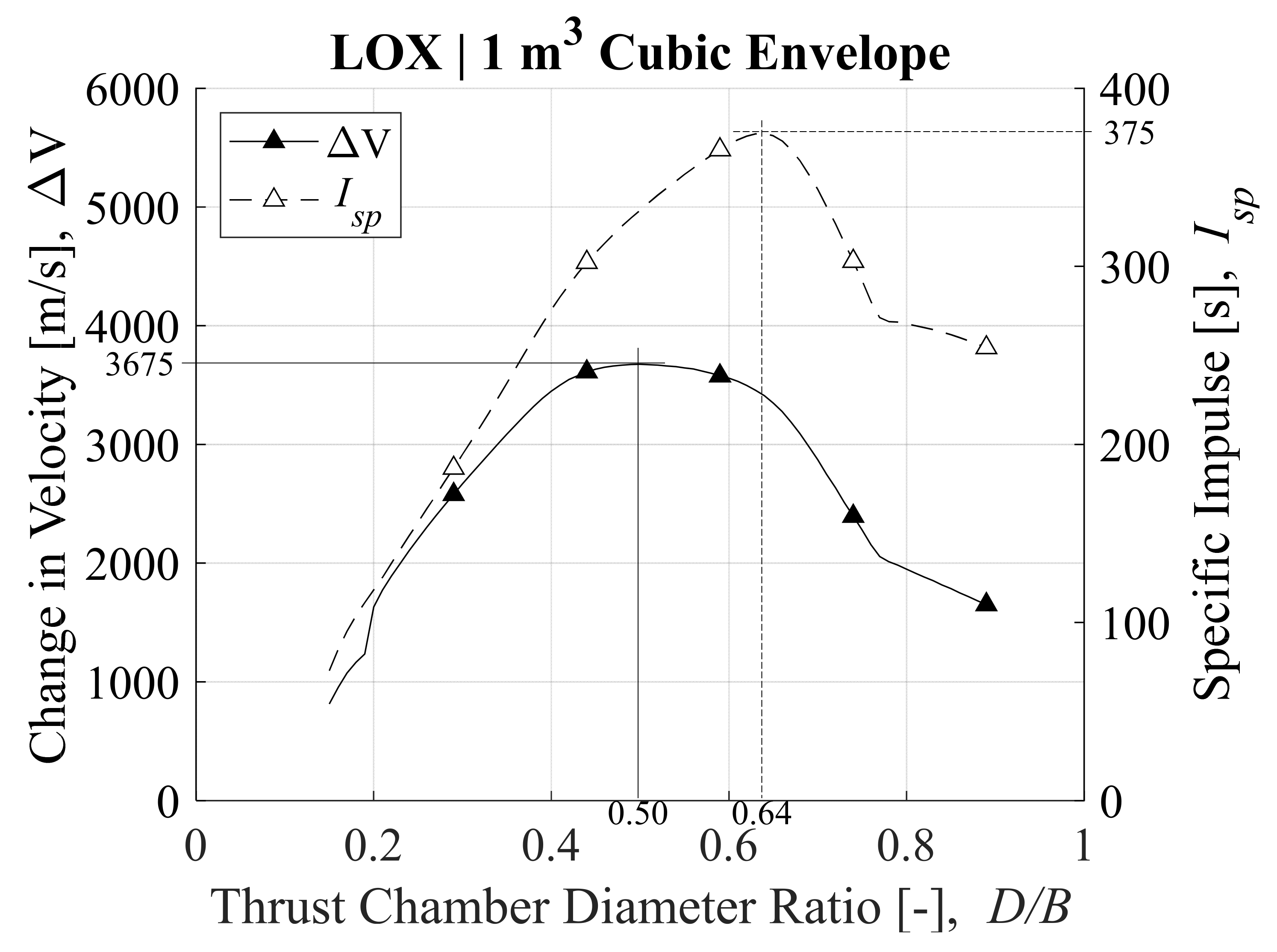
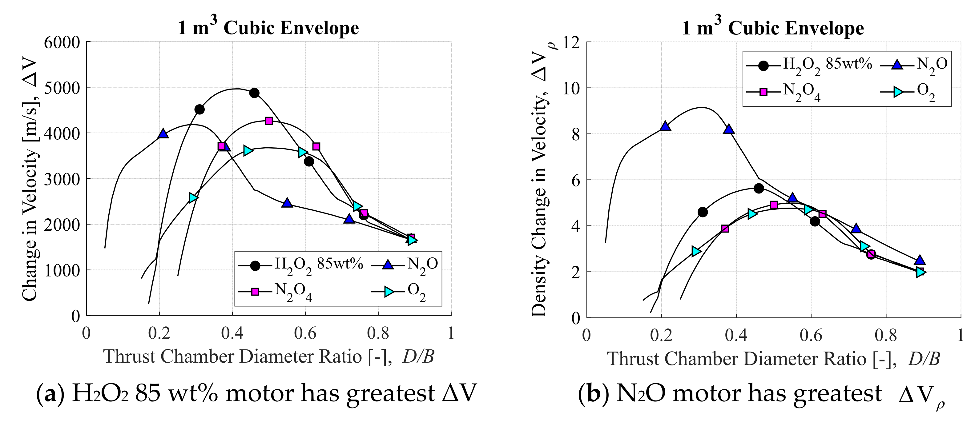
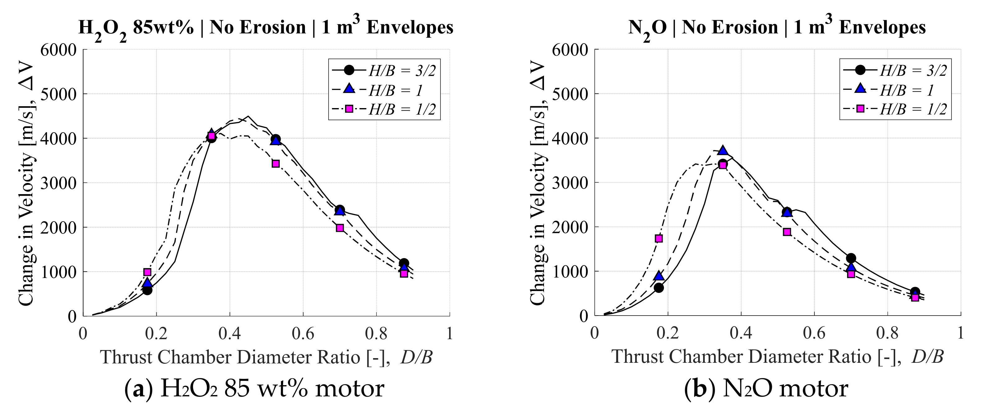
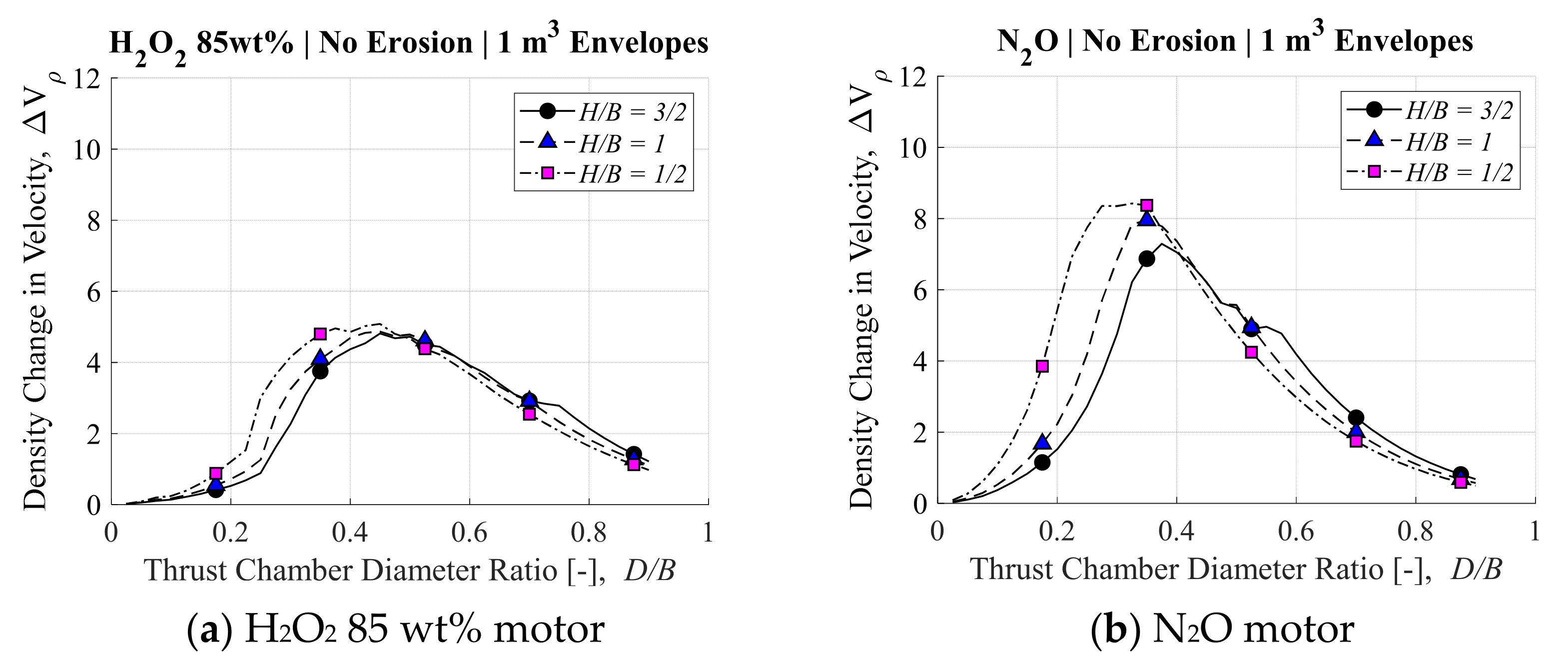
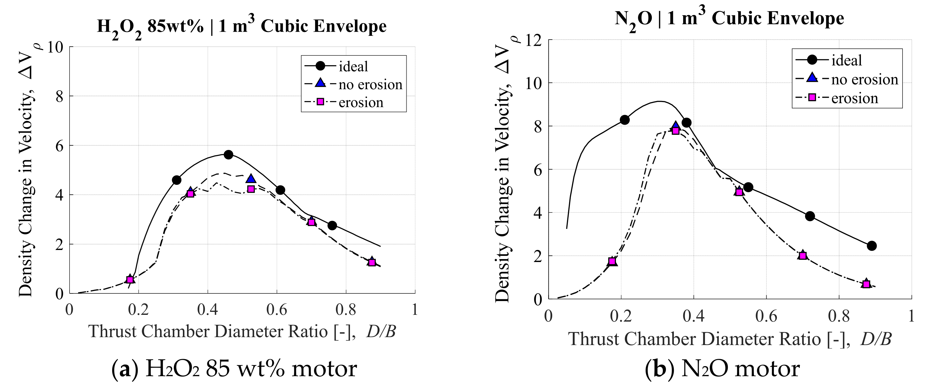
3.1. Ideal Post-Boost Stage and Kick Motor Results

In this first part of the research, the ideal performance of each kick motor will be investigated. Here, “ideal” means that the Isp is assumed to be constant in time based on the values as presented in Figure 4. This assumption entails that the O/F is also constant in time, which is determined according the standardized motor designs in Section 2.4, configured as shown in Section 2.3, constrained to the envelopes introduced in Section 2.2. The only independent parameter is the thrust chamber diameter, which once defined, constrains the pressure vessel designs as well. Simply put, the thrust chamber diameter determines the O/F for a given envelope. Since O/F determines Isp, the thrust chamber diameter determines the Isp. Consequently, the oxidizer mass flow rate and related equations from Section 2.5 are not necessary for calculating ΔV as determined by Equation (1). However, when referencing Isp from NASA CEA, chamber pressure is required as an input. For the sake of identifying the ideal performance of each motor, this pressure was set to a relatively high value of 5 MPa for all calculations. The results of this simplified analysis are used to inform us of the maximum possible performance of the standard motor designs of this paper.
The results of the calculations for ΔV for each of the four oxidizers: H2O2 85 wt%, N2O, N2O4, and LOX, are shown in the plots in Figure 10 for each of the three envelopes: H/B = 1/2, H/B = 1, H/B = 3/2.
One key takeaway from this comparison is that the H2O2 85 wt% motor has the highest ΔV for the given envelope constraints, while the LOX motor has the lowest. Based on Isp and storage density alone, this conclusion is rather unexpected. When considering the mass penalty for requiring a large thrust chamber, LOX-based post-boost stages need to be highly optimized for thrust chamber mass to become competitive with the other oxidizers. Another key takeaway is that when the mechanism of achieving a given O/F is not considered, the tall and skinny motors perform better than the short and flat ones, for all oxidizers. This is also a consequence of the mass penalty of the thrust chamber. The thrust chamber mass increases with the square of the diameter, but proportionally to height, meaning that taller and skinnier thrust chambers have greater propellant mass fractions which lead to greater ΔV. Figure 11 shows that the thrust chamber diameter which optimizes ΔV in the cubic (i.e., H/B = 1) LOX motor is less than that which optimizes Isp. In the ideal case where all propellants are consumed, this would mean that the motor is operating at an O/F slightly more O-rich than the optimum value. In other words, the LOX motor should be operated in more fuel rich conditions, but it cannot be because the mass penalty of increasing the thrust chamber size is too great.
Lastly, it is useful to compare the four oxidizers directly, as is shown in the plots in Figure 12. Here the plots for the cubic envelope have been selected for comparison purposes. As previously mentioned, and obvious from Figure 12a, the H2O2 85 wt% outperforms the others in terms of ΔV by a margin of more than 15%, with N2O4 as the next best performing, and LOX as the least performing. However, there is one more consideration that is essential for understanding all the tradeoffs at hand. In the context of an actual launch, where these motors are added to the payload compartment at the expense of the space and mass of the payload, the wet mass of these motors must also be considered. To account for this important factor, a “density change in velocity,” Δ V ρ ((m/s)/(kg/m3)), term is introduced, and is shown in Figure 12b. The density change in velocity is determined by dividing the ΔV by the motor density, defined as the wet mass divided by the envelope volume. This calculation is shown as Equation (10) for clarification:
Δ V ρ = Δ V × V e n v e l o p e / M w e t .
The N2O motor outperforms the other motors by a margin of 50% in terms of density change in velocity. In other words, the N2O motors are significantly lighter than the others when taking up the same envelope space, and have a similar self-ΔV.
In this research which controlled for the envelope volume as Venvelope = 1, dividing by Mwet alone would result in the same values for Δ V ρ . However, if volume is not included in Equation (10), the Δ V ρ would scale with mass for all other cases where the volume is not one. Thus, as a term which is applicable to extrapolation, the motor density must be used. In this sense, the density change in velocity contains all the information important to the end user, who understands both the envelope volume and mass limitations of the launch vehicle. For an end user with little space yet ample mass budget, the H2O2 motor is the best option. For an end user with ample space yet a strict mass budget, the N2O motor is best option. Answering the question of where exactly the line is drawn in selecting between these two types of systems is outside the scope of this paper.

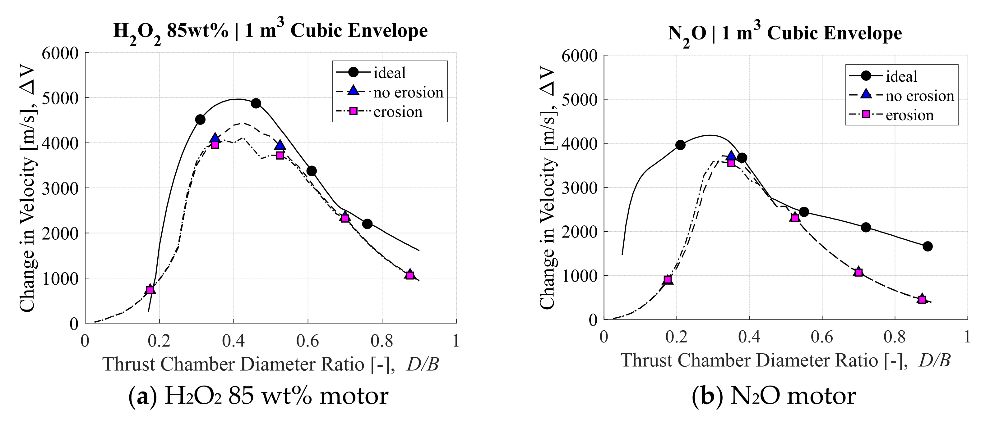
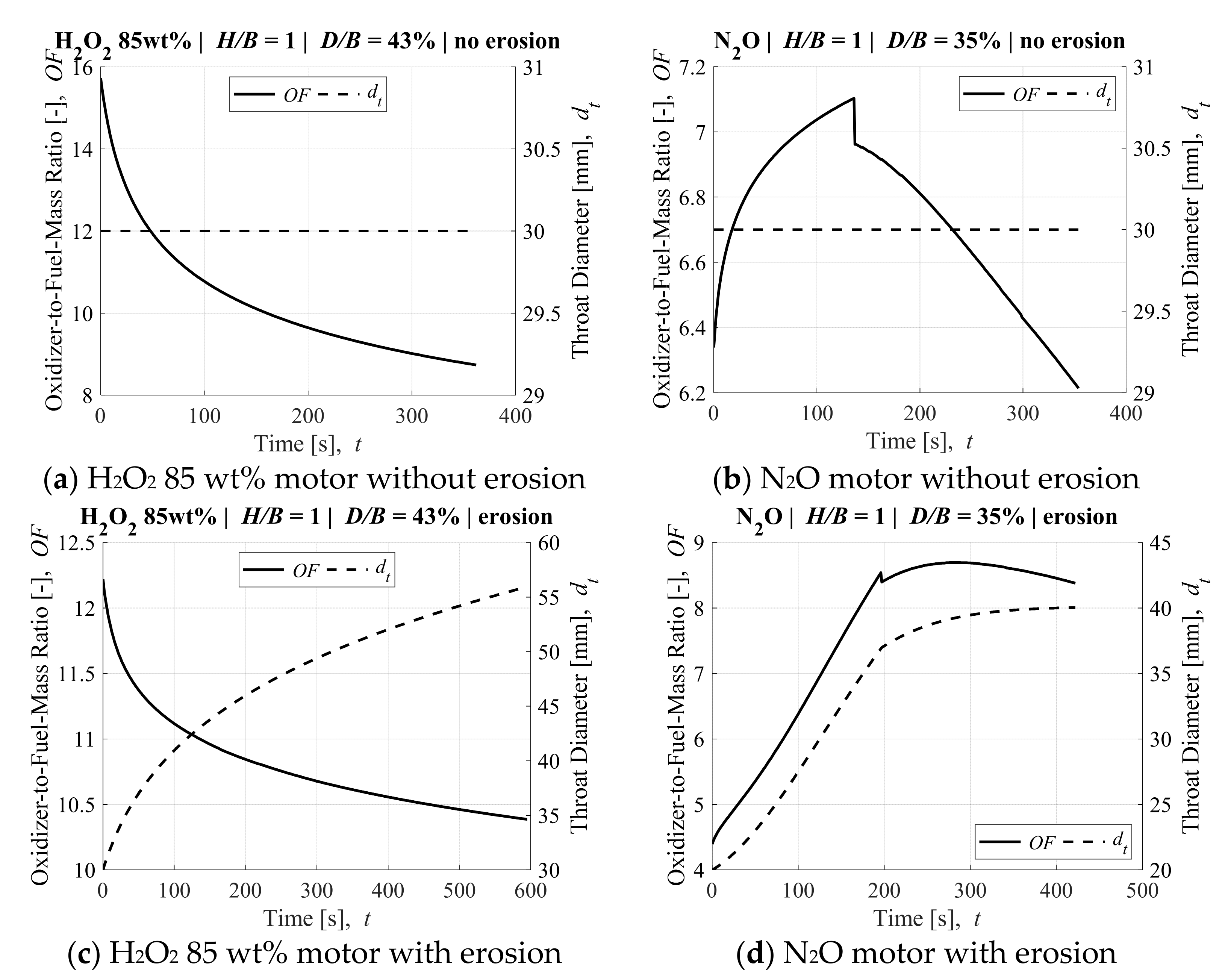
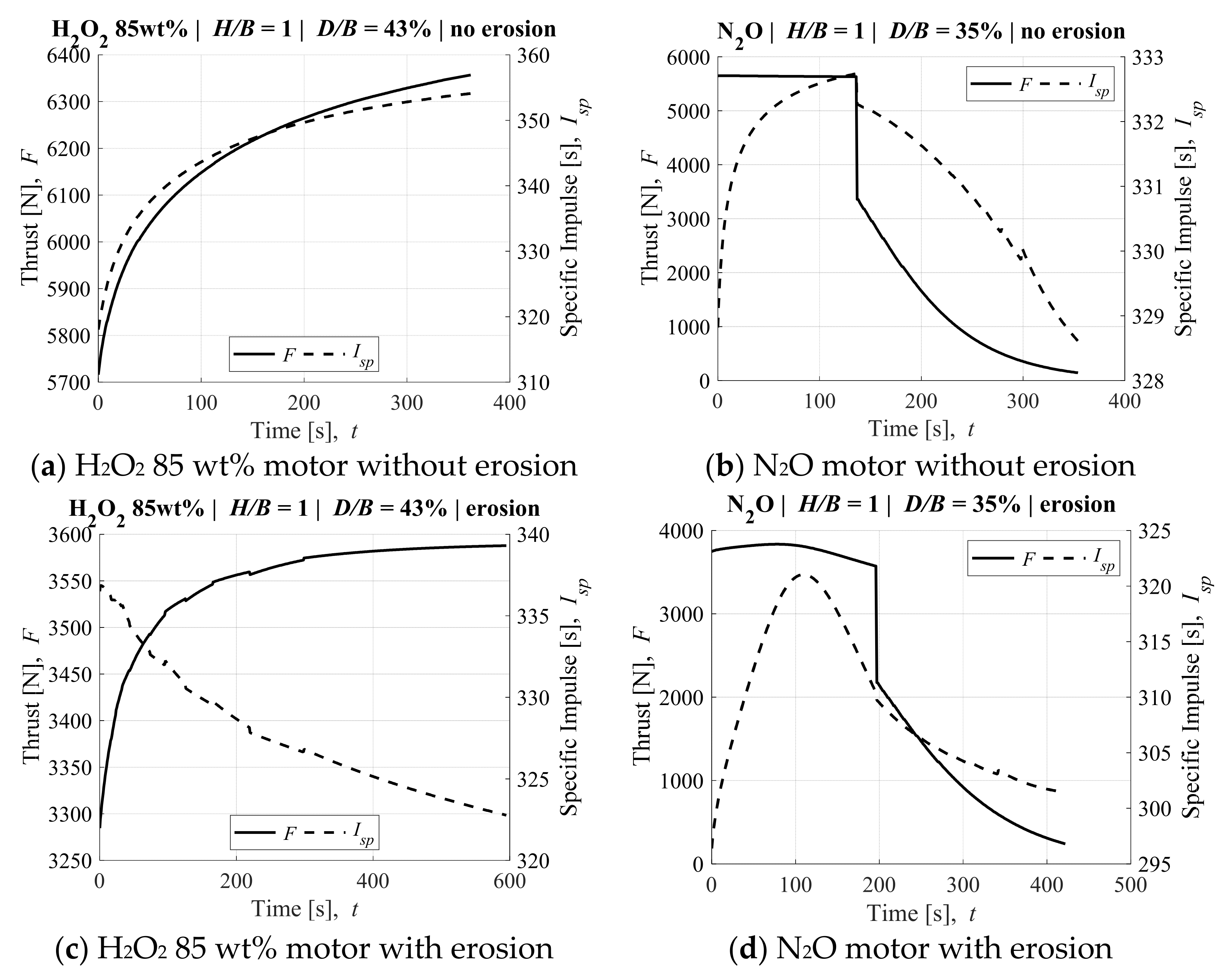
3.2. Impact of O/F Shift and Nozzle Erosion on Ideal Performance

In this second part of the research, more realistic estimates of ΔV will be calculated to understand how well hybrid rockets align with their theoretical ideal performance. This time, the ΔV are calculated according to the internal ballistics simulation algorithm in Section 2.5. These calculations are carried out in two sets. In the first set of calculations, nozzle throat erosion is neglected, and in the second it is calculated by assuming that the nozzle throat wall temperature Tw is always 80% of the combustion gas temperature at the throat, which is the upper end of the values that the authors have experienced in practice.
Due to the increased number of possible outcomes and avenues of investigation available, as well as the increased computational cost of calculating ΔV, the decision was made to focus this part of the research on the two most promising candidates from the previous section: H2O2 85 wt% for maximizing ΔV; and N2O for maximizing Δ V ρ . Moreover, the empirical formulations for the H2O2 85 wt% are not available in the literature, and so the empirical coefficients for the LOX case in Table 4 were implemented instead. Since the mass fraction of hydrogen content in H2O2 85 wt% is roughly 7%, meaning that the remaining 93% is oxygen, this approximation seems appropriate enough for the purposes of the investigation at hand.
In addition to the thrust chamber diameter ratio D/B, the thrust chamber injector flow area AD and nozzle throat area At need to be treated as independent variables. Due to the nature of the algorithm, which contains multiple iterative loops as well as decisions to switch between mass flow rate equations, a brute force method was used to find the greatest ΔV within a 2D domain of AD and At for every value of D/B. This domain was created by defining the injector as having 10 holes, and varying the size of the injector hole diameters dinj, and nozzle throat diameters dt, to ensure a wide range of flowrates, chamber pressures, and thrusts would be considered. These domains of calculations are summarized in Table 5. Note that the authors originally tried several optimization techniques to reduce the number of calculations required to find the maximum ΔV, however no method consistently converged on a value that matched or bettered the brute force method described above, which calculated ΔV along a grid of fixed values. In other words, the landscape of the solution space is changing drastically for every value of D/B and between oxidizers.
One benefit of using a brute force grid search type for the maximum ΔV is that the contour maps of the solution space can be checked at will. The contour maps of the highest performing motors are shown in Figure 13. The solution space of the N2O motor in Figure 13b, although not easy to replicate with simple algebra, is much more straight forward than the solution space of the H2O2 85 wt% motor in Figure 13a. In a positive way, there is not such a narrow range of injector hole diameters—roughly 1.5 to 3 mm—that result in ΔV > 3500 m/s when the throat diameter is 30 mm. Furthermore, there is an even larger range, two separate ranges in fact, of such values for the H2O2 85 wt% motor where ΔV > 4000 m/s. However, of some concern for applying these motors in practice is that in both cases these regions reside next to cliffs of meaningless solutions (ΔV < 500 m/s). Further investigations regarding this landscape require an analysis outside of the purview and objectives of this research. The results of ΔV for each type of motor without nozzle erosion for each envelope are plotted in Figure 14, and the corresponding results of Δ V ρ are plotted in Figure 15. One takeaway from Figure 14 and Figure 15 is that the thrust chamber diameter ratio that corresponds to the maximum ΔV of the H2O2 85 wt% motor is only slightly affected by the envelope shape, and more so for the H2O2 85 wt% motor than the N2O motor when internal ballistics simulations are used to estimate ΔV. This is because there is simply much more oxidizer mass than the nitrous oxide motor due to the higher density. Recall from Figure 4 that the optimum O/F are close in value for both oxidizers, yet since the density of H2O2 85 wt% is more than twice that of N2O, a larger thrust chamber containing twice as much fuel is necessary to achieve this optimum O/F. Meanwhile, the fuel length is fixed, so variation in burning surface area during firing is exacerbated and leads to more sporadic results. Another takeaway is that plots of both motors skew to the left—i.e., lower D/B—for lower values of H/B. Once again, this trend reflects the dependence of fuel and oxidizer mass on thrust chamber diameter when the height is fixed. Since the skew is to the left, it means that the shorter the H/B, the smaller the motor diameter which is needed to maximize performance, regardless of the oxidizer used. Lastly, the magnitude of the skew is greatest for the Δ V ρ plots in Figure 15b, which show that the most mass efficient motor of this study is the short and flat—i.e., H/B = ½—N2O motor, with Δ V ρ > 8 m4/kg-s.
The results of ΔV for each type of motor with nozzle throat erosion for the cubic envelope are plotted in Figure 16, and the corresponding results of Δ V ρ are plotted in Figure 17. Table 6 summarizes the best performing cases for each motor with and without nozzle erosion. By narrowing the presentation of results down to a single envelope, the plots within each figure can compare the three cases of: ideal motor performance, motor performance base on internal ballistics simulations without nozzle erosion, and corresponding simulations with nozzle erosion. In this way, Figure 16 and Figure 17 most directly answer the main questions of the research objectives, regarding how well hybrid rockets can be expected to perform in theory, and to what degree O/F shift and nozzle throat erosion affect this performance.
The results of Figure 16 and Figure 17, and Table 6 are enlightening. O/F shift and/or O/F design challenges related to fuel regression rate are responsible for a major departure from theoretical ΔV in both motors: a decrease of roughly 600 m/s, or 12% from 5000 m/s to 4400 m/s in the H2O2 85 wt% motor; and a decrease of roughly 400 m/s, or 10% from 4100 m/s to 3700 m/s in the N2O motor. It is also clear that nozzle erosion is more detrimental to the H2O2 85 wt% motor, leading to an additional departure from theoretical ΔV of 300 m/s or 7%, versus 150 m/s, or 4% for the N2O motor.
Interestingly, both the H2O2 85 wt% motor and N2O motor result in similar values for initial throat diameter and combustion time when nozzle erosion is neglected, making this comparison particularly relevant. It is worth mentioning that this similarity is unintentional. Recall that all possible sets of nozzle throat diameter and injector hole diameter are considered for both motors (see Table 5 and Figure 13), and the motors which resulted in the highest ΔV are selected from this body of results. No other selection criteria are employed, and no other constrains are placed on the calculations outside of the shutdown criteria (see Section 2.5 final paragraph).
Figure 18 and Figure 19 elucidate the internal ballistics calculations that result in the plots of Figure 16 and Figure 17, and solutions of Table 6. Figure 18 shows the O/F shift and nozzle throat diameter histories of the highest performing cases from Figure 17, with and without erosion. The figures were not made to have matching axes, due to the variations in magnitudes of the abscissa and ordinates for each motor, with and without erosion. Thus, a direct comparison cannot be made between subfigures. Instead, a brief summary of key takeaways will be presented here instead.
First, comparing Figure 18a,c shows that O/F shifts from high to low in both H2O2 85 wt% motors, and that the main difference between motors with and without nozzle erosion is the range over which O/F shift occurs: from 16 to 9 without nozzle erosion; and from 12.5 to 10.5 with nozzle erosion. Comparing Figure 19a,c shows that the impact of O/F shift on Isp is significant. The value of Isp quickly surpasses 340 s in the H2O2 85 wt% motor without nozzle erosion, however never reaches this value when erosion occurs.
Second, comparing Figure 18b,d shows that the O/F shift differs between the N2O motors with and without nozzle erosion. In the motor without nozzle erosion, O/F increases from six to seven, before decreasing back to six by the end of the firing. In the motor with nozzle erosion, O/F increases from 4.5 to 8.5, where it remains relatively steady until the end of firing. The reason O/F shift is positive at first is related to the mass flux exponents n of Equation (5) and Table 3. When n > 0.5—as in the reference value for N2O—and oxidizer mass flow rate is constant, O/F shift is positive and vice versa. However, during firing, the N2O supply mode switches from flashing liquid flow to choked gas flow, leading to a rapid drop followed by a gradual decrease in flow rate until the end of the firing. This explains why the O/F shift switches from being positive to negative during firing. When nozzle erosion occurs, the chamber pressure decreases, leading to a decrease in fuel mass consumption flow rate (see Equation (5)). As a result, the O/F remains relatively constant, even though both propellants’ flow rates are decreasing in time.
The reason this flow change takes places is related to the storage conditions of N2O in the oxidizer vessels and the self-fed supply procedure. The N2O is stored at 550 kg/m3 so that it remains as a saturated liquid even at the critical temperature of 309 K. However, the self-feeding supply of N2O refrigerates the mass remaining in the vessel, which means that the density of the liquid portion of oxidizer increases in time, taking up less and less volume per unit mass. At some time, no liquid remains in the oxidizer vessels and the N2O is supplied as a coked gas in a blow-down configuration
Comparing Figure 19b,d shows that the impact of the O/F shift on Isp is significant in the N2O motor as well. The Isp of the motor without nozzle erosion remains between 328 s and 333 s, or 1.5% of the mean for the entire duration of firing, whereas it varies between 295 s and 325 s, or 4.8% of the mean in the motor with nozzle erosion. Furthermore, the thrust of the N2O motor rapidly drops roughly 2800 N in value about 1/3 into firing.

4. Discussion

4.1. Technologies for Reducing O/F Shift and Nozzle Erosion

There are four key technologies currently under development by the authors and other researchers which aim to eliminate O/F shift, and as a result will also reduce the impact of nozzle erosion. Recall that for both the H2O2 85 wt% and N2O motors, O/F shift alone results in departures from theoretical ΔV of around 9–12%, which are further exacerbated by nozzle erosion by an additional 4–7%. Thus, eliminating O/F shift and nozzle erosion completely will lead to improvements in ΔV of 14–19%.
The first technology which may eliminate O/F shift is the axial-injection end-burning (AIEB) type hybrid rocket fuel. This type of fuel has a porous fuel grain through which oxidizer flows, such that combustion takes place along the aft-end surface of the fuel, rather than within the openings in the fuel. In this configuration, the burning surface area remains constant in time, and the fuel mass consumption rate depends solely on chamber pressure. Thus, O/F remains constant so long as the chamber pressure remains constant. Recently, this technology has matured, with demonstrations from three institutions and the use of various fuel and oxidizer materials [35,36,37,38]. The main issues remaining are the prevention of flame-spreading into the fuel at pressures greater than 1.5 MPa or so, losses in combustion efficiency due to the ejection of unburned fuel particles [39,40], and the negative effect of nozzle erosion on chamber pressure.
The second technology which may eliminate the O/F shift is the active control of oxidizer supply to match the fuel consumption rate during firing. This technology has been demonstrated with some success in the SOFT and A-SOFT type hybrid rockets [41,42]. The main challenge of the active oxidizer flow for O/F control is that estimating the fuel mass consumption rate in real time requires some additional technology, which has not matured yet.
The third and fourth technologies are related to the prevention or reduction of nozzle throat erosion. The third technology is the use of an erosion-resistant material at the nozzle throat. For example, Kamps et al. reported that coating the throat of a conventional graphite nozzle with SiC prevented erosion completely in a five second firing test [43]. D’lia et al. [44] and Whitmore et al. [45] achieved erosion reduction in longer firing durations using throat inserts made of customized erosion-mitigating materials with varying degrees of success. The fourth technology is the active cooling of a carbon-based nozzlewith the aim of delaying or preventing nozzle throat erosion, which has only recently been proposed. The basis of this technology is that the nozzle throat erosion rate is negligibly small at temperatures below 1500 K, and increases rapidly with temperatures between 1500 K and 2000 K. Thus, if the nozzle can be cooled to 2000 K or below, erosion can be reduced, and if it can be cooled to 1500 K or below, erosion can be prevented. Initial findings which support the viability of an actively cooled carbon-based nozzle have been reported by Ito et al. [46]. Note that with either technology, hybrid rockets using nitrous oxide will have roughly half the erosion rate of hybrid rockets using pure oxygen, or oxygen-rich oxidizers such as high weight percentage hydrogen peroxide, because of the decreased presence of oxidizing species in the combustion gas—see [30,47].

4.2. Nonintuitive Nature of the Results

The findings of Section 2 and Section 3 may be obvious to some readers; however, they came as a surprise to the authors. When entering into this study the authors felt as a general principle that oxidizers with a greater density would tend to be more mass-efficient, and consequently when considering the density change in velocity (ΔVρ), N2O, which has the lowest density, would have the worst performance. Only after grasping the impact of requiring the pressurizing systems of the other oxidizers to fit into the limited space surrounding the oxidizer vessels was it clear to what extent the pressurizing feed systems reduce ΔVρ. This outlook is reflected in previous research as well. Nitrous oxide appears to have been neglected from an otherwise groundbreaking analysis in previous research, based on the viewpoint that the relatively low storage density would prevent it from being comparable in performance to other oxidizers [48]. Lastly, LOX is commonly selected for use as an oxidizer for its high Isp. For this reason, we expected the LOX motor to match or perhaps surpass the other oxidizers in ΔV. In fact, LOX resulted in the overall worst theoretical ΔV and ΔVρ. The reason is that LOX performs best at an O/F of around two, which is at least twice as low as the optimum O/F of the other oxidizers. Since the thrust chamber can never be made as light as the surrounding pressure vessels, there is a non-negligible penalty to require larger fuel grains. In the rocket design conditions of this study, this penalty was so large as to completely negate the advantage that LOX has in Isp.

5. Conclusions

Hybrid rockets are now the core technology for numerous Earth launch vehicle business ventures, which means that the current state-of-the-art hybrid rockets have achieved sufficiently high thrust-to-weight ratios as to compete with conventional liquid-bipropellant rockets and solid rockets. This is a testament to the decades of R&D focused on achieving high thrust-to-weight ratios with the hybrid rocket propellant configuration. Now there is increasing demand for a non-explosive yet powerful rocket for in-space transportation, beckoning hybrid rocket developers to propose solutions. However, the high thrust-to-weight ratio hybrid rockets of previous development are not directly transferable to use as in-space thrusters are, often categorized as “post-boost stages” and “kick motors.” That is, post-boost stages and kick motors have mass and volume restrictions that are fixed by the launch vehicle, and they do not benefit from accelerations greater than Earth’s gravitation acceleration. Moreover, they have additional requirements, such as multiple ignitions in vacuum, and careful control of solid particle debris. This paper carefully evaluated key aspects of hybrid rockets to evaluate their potential for use as post-boost stages and kick motors. A robust design algorithm, which is applicable to all major hybrid rocket configurations, was presented and used to evaluate the effect of O/F shift and nozzle erosion on ΔV.
The results may be surprising even to experienced rocket engineers because the complexity of interactions between design constraints is nonintuitive and impossible without the help of a computer. Among the four most common liquid hybrid rocket oxidizers: H2O2 (85wt%), N2O, N2O4, and LOX, H2O2 is shown to outperform the others in theoretical ΔV by more than 10%, even though it does not have to the highest Isp. In terms of theoretical density ΔV, which is a term for normalizing ΔV by the density of the thruster, N2O outperforms the other oxidizer by 50%, even though it has the lowest storage density. Furthermore, LOX has both the worst theoretical ΔV and density ΔV, even though it has the highest Isp. This is due primarily to the mass penalty of requiring a larger thrust chamber or pressurizing system, and having to fit the pressurizing system in the limited space around the oxidizer vessels and thrust chamber. Further analysis of the top-performing motors, the H2O2 85 wt% and N2O motors, shows that they lose 9–12% in ΔV due to O/F shift. Moreover, the H2O2 85 wt% motors lose another 7% in ΔV due to nozzle throat erosion, and the N2O motors another 4%. Nonetheless, even with O/F shift and nozzle erosion, a one-cubic-meter H2O2 85 wt% motor can accelerate itself (916 kg) upwards of 4000 m/s, and a N2O motor (456 kg) 3550 m/s.

Author Contributions

Conceptualization, L.K. and S.H.; methodology, L.K. and S.H.; software, L.K.; formal analysis, L.K. and H.N.; investigation, L.K.; resources, L.K. and H.N.; data curation, L.K.; writing—original draft preparation, L.K.; writing—review and editing, S.H. and H.N.; supervision, H.N.; project administration, L.K.; funding acquisition, L.K. and H.N. All authors have read and agreed to the published version of the manuscript.

Funding

This research was funded by the Adaptable and Seamless Technology Transfer Program through Target-driven R&D (A-STEP) from Japan Science and Technology Agency (JST), by the Research and Development Grant Program (Engineering) from the Institute of Space and Astronautical Science, Japan Aerospace Exploration Agency (JAXA), and supported by f3 Engineering Education and Research Center, Faculty of Engineering, Hokkaido University.

Institutional Review Board Statement

Not applicable.

Informed Consent Statement

Not applicable.

Data Availability Statement

Not applicable.

Acknowledgments

The authors would like to thank Erika Uchiyama and Kengo Yamamoto for their guidance and advice in selecting an appropriate envelope size and shape, as well as appropriate thrust chamber components.

Conflicts of Interest

The authors declare no conflict of interest.

Nomenclature

a, m, nfuel regression rate constants, Equation (5)
Aarea, m2
AO/Foxidizer-to-fuel cross-sectional area ratio
b, E, n, β1, β2,β3nozzle erosion rate constants, Equation (7)
c*characteristic exhaust velocity, m/s
CD, CGdimensionless flow coefficients
dinner diameter, m
Douter diameter, m or binary mass diffusivity, m2/s
D/B(thrust chamber) diameter-to-base ratio
Fthrust, N
F.S.factor of safety
g(Earth) gravitational acceleration, ≅9.8 m/s2
H/B(envelope) height-to-base ratio
H/D(envelope) height-to-(thrust chamber) diameter ratio
Ispspecific impulse, s
MEOPmaximum expected operation pressure, Pa
m ˙ mass flow rate, kg/s
M(initial) propellant mass, kg
M(initial) wet mass, kg
O/Foxidizer-to-fuel-mass ratio
Ppressure, Pa
rnozzle throat or fuel port radius, m
ReReynolds number
ScSchmidt number
t(wall) thickness, m
Ttemperature, K
ΔVchange in velocity, m/s
ΔVρdensity change in velocity, m4/kg-s
εnozzle expansion ratio
γspecific heat ratio
Φequivalence ratio, Φ > 1 is fuel-rich
ρDensity, kg/m3
σtensile strength, Pa
Subscripts
bsburning surface
cthrust chamber (position)
dw, up(orifice) downstream, upstream (position)
e, t, w(nozzle) exit, throat, wall (position)
fu, n, oxfuel, nozzle, oxidizer
injinjector

Appendix A

Figure A1. Comparison of Chemical Rocket Configurations.
Aerospace 08 00253 g0a1

References

  1. Altman, D.; Holzman, A. Overview and History of Hybrid Rocket Propulsion. In Fundamentals of Hybrid Rocket Combustion and Propulsion, 1st ed.; Chiaverini, M.J., Kuo, K.K., Eds.; American Institute of Aeronautics and Astronautics: Renton, VA, USA, 2007; Progress in Aeronautics and Astronautics; Volume 218, pp. 1–36. [Google Scholar]
  2. Chiaverini, M. Review of Solid-Fuel Regression Rate in Classical and Nonclassical Hybrid Rocket Motors. In Fundamentals of Hybrid Rocket Combustion and Propulsion, 1st ed.; Chiaverini, M.J., Kuo, K.K., Eds.; American Institute of Aeronautics and Astronautics: Renton, VA, USA, 2007; Progress in Aeronautics and Astronautics; Volume 218, pp. 37–125. [Google Scholar]
  3. Story, G.; Arves, J. Flight Testing of Hybrid-Powered Vehicles. In Fundamentals of Hybrid Rocket Combustion and Propulsion, 1st ed.; Chiaverini, M.J., Kuo, K.K., Eds.; American Institute of Aeronautics and Astronautics: Renton, VA, USA, 2007; Progress in Aeronautics and Astronautics; Volume 218, pp. 553–591. [Google Scholar]
  4. Ansari X-Prize. Available online: https://www.xprize.org/prizes/ansari (accessed on 25 July 2021).
  5. Brinkmann, P. Rocket Crafters Pivots with New Patents for 3D-Printed Fuel. Available online: https://www.spacedaily.com/reports/Florida_space_startup_Rocket_Crafters_pivots_with_new_patents_for_3D_printed_fuel_999.html (accessed on 25 July 2021).
  6. Vaya Space. Available online: https://www.vayaspace.com (accessed on 25 July 2021).
  7. Gilmour Space. Available online: https://www.gspacetech.com (accessed on 25 July 2021).
  8. Cecil, O.; Majdalani, J. Several Hybrid Rocket Technologies Hit Advanced Test Stages. Aerospace America. Available online: https://aerospaceamerica.aiaa.org/year-in-review/several-hybrid-rocket-technologies-hit-advanced-test-stages (accessed on 25 July 2021).
  9. Chen, Y.S.; Wu, B. Development of a Small Launch Vehicle with Hybrid Rocket Propulsion. In Proceedings of the AIAA Propulsion and Energy 2018 Forum, Cincinnati, OH, USA, 9–11 July 2018. AIAA-Paper 2018-4835. [Google Scholar]
  10. Chen, Y.S. Development of Hapith Small Launch Vehicle Based on Hybrid Rocket Propulsion. In Proceedings of the AIAA Propulsion and Energy 2019 Forum, Indianapolis, IND, USA, 19–22 August 2019. AIAA-Paper 2019-3837. [Google Scholar]
  11. Faenza, M.G.; Boiron, A.; Haemmerli, B.; Verberne, O. Development of Nucleus Hybrid Propulsion System: Enabling a Successful Flight Demonstration. In Proceedings of the AIAA Propulsion and Energy 2019 Forum, Indianapolis, IND, USA, 19–22 August 2019. AIAA-Paper 2019-3839. [Google Scholar]
  12. Schmierer, C.; Kobald, M.; Tomilin, K.; Fischer, U. Low Cost Small-Satellite Access to Space Using Hybrid Rocket Propulsion. Acta Astronaut. 2019, 159, 578–583. [Google Scholar] [CrossRef]
  13. Henry, C. DLR Spinoff HyImpulse Plans Small Launcher Debut. Available online: https://spacenews.com/dlr-spinoff-hyimpulse-plans-small-launcher-debut-in-2022 (accessed on 25 July 2021).
  14. Firehawk. Available online: https://www.firehawkaerospace.com (accessed on 25 July 2021).
  15. Gamal, H.; Matusiewicz, A.; Magiera, R.; Hubert, D.; Karolewski, L.; Zielinski, K. Design, Analysis and Testing of a Hybrid Rocket Engine with a Multi-port Nozzle. In Proceedings of the AIAA Propulsion and Energy 2018 Forum, Cincinnati, OH, USA, 9–11 July 2018. AIAA-Paper 2018-4666. [Google Scholar]
  16. Space Forest. Available online: https://spaceforest.pl/sir-suborbital-inexpensive-rocket/ (accessed on 25 July 2021).
  17. T4i Hybrid Propellant. Available online: https://www.t4innovation.com/hybrid-propellant (accessed on 25 July 2021).
  18. Eilers, S.D.; Whitmore, S.; Peterson, Z. Multiple Use Hybrid Rocket Motor. U.S. Patent US20140026537A1, 30 January 2014. [Google Scholar]
  19. Whitmore, S.A. Nytrox as “Drop-in” Replacement for Gaseous Oxygen in SmallSat Hybrid Propulsion Systems. Aerospace 2020, 7, 43. [Google Scholar] [CrossRef] [Green Version]
  20. Jens, E.T.; Cantwell, B.J.; Hubbard, G.S. Hybrid Rocket Propulsion Systems for Outer Planet Exploration Missions. Acta Astronaut. 2016, 128, 119–130. [Google Scholar] [CrossRef]
  21. Jens, E.T.; Karp, A.C.; Rabinovitch, J.; Nakazono, B. Hybrid Propulsion System Enabling Orbit Insertion Delta-Vs within a 12 U Spacecraft. In Proceedings of the 2019 IEEE Aerospace Conference, Big Sky, MT, USA, 2–9 March 2019. [Google Scholar]
  22. Kamps, L.; Molas-Roca, P.; Uchiyama, E.; Takanashi, T.; Nagata, H. Development of N2O/HDPE Hybrid Rocket for Microsatellite Propulsion. In Proceedings of the 70th International Astronautical Congress, Washington, DC, USA, 21–25 October 2019. [Google Scholar]
  23. Kamps, L.; Sakurai, K.; Saito, Y.; Nagata, H. Comprehensive Data Reduction for N2O/HDPE Hybrid Rocket Motor Performance Evaluation. Aerospace 2019, 6, 45. [Google Scholar] [CrossRef] [Green Version]
  24. Karp, A.C.; Nakazono, B.; Shotwell, R.; Benito, J.; Vaughan, D. Technology Development Plan and Preliminary Results for a Low Temperature Hybrid Mars Ascent Vehicle Concept. In Proceedings of the 53rd AIAA/SAE/ASEE Joint Propulsion Conference, Atlanta, GA, USA, 10–12 July 2017. AIAA Paper 2017-4900. [Google Scholar]
  25. Story, G.; Karp, A.; Nakazono, B.; Evans, B.; Whittinghill, G. Mars Ascent Vehicle Hybrid Propulsion Effort. In Proceedings of the AIAA Propulsion and Energy 2020 Forum, Virtual Event, 24–28 August 2020. AIAA Paper 2020-3727. [Google Scholar]
  26. Process for Limiting Orbital Debris. NASA-STD-8719.14A. 2011. Available online: https://explorers.larc.nasa.gov/HPMIDEX/pdf_files/10_nasa-std-8719.14a_with_change_1.pdf (accessed on 1 July 2021).
  27. Marks, P. Dodging Debris. Aerospace America. Available online: https://aerospaceamerica.aiaa.org/features/dodging-debris (accessed on 25 July 2021).
  28. Molas-Roca, P. Design of Scalable Hybrid Rocket Motor for Space Propulsion Applications. In Proceedings of the 70th International Astronautical Congress, Washington, DC, USA, 21–25 October 2019. [Google Scholar]
  29. Gordon, S.; McBride, B. Computer Program for Calculation of Complex Chemical Equilibrium Compositions and Applications; National Aeronautics and Space Administration: Lewis Research Center, OH, USA, 1994; NASA RP-1311. [Google Scholar]
  30. Kamps, L.; Hirai, S.; Sakurai, K.; Viscor, T.; Saito, Y.; Guan, R.; Isochi, H.; Adachi, N.; Itoh, M.; Nagata, H. Investigation of Graphite Nozzle Erosion in Hybrid Rockets Using Oxygen/High-Density Polyethylene. J. Propuls. Power 2020, 36, 423–434. [Google Scholar] [CrossRef]
  31. Kamps, L.; Sakurai, K.; Ozawa, K.; Nagata, H. Investigation of Graphite Nozzle Erosion in Hybrid Rockets Using N2O/HDPE. In Proceedings of the AIAA Propulsion and Energy 2019 Forum, Indianapolis, IN, USA, 19–22 August 2019. AIAA Paper 2019-4264. [Google Scholar]
  32. Ito, S.; Kamps, L.; Nagata, H. Fuel Regression Characteristics in Hybrid Rockets Using Nitrous Oxide/High-Density Polyethylene. J. Propuls. Power 2020, 37, 342–348. [Google Scholar] [CrossRef]
  33. Carmicino, C.; Sorge, A.R. Role of Injection in Hybrid Rockets Regression Rate Behavior. J. Propuls. Power 2005, 21, 606–612. [Google Scholar] [CrossRef]
  34. Zimmerman, J.E.; Waxman, B.S.; Cantwell, B.J.; Zilliac, G.G. Review and Evaluation of Models for Self-Pressurizing Propellant Tank Dynamics. In Proceedings of the 49th AIAA/SAE/ASEE Joint Propulsion Conference, San Jose, CA, USA, 14–17 July 2013. AIAA Paper 2013-4045. [Google Scholar]
  35. Nagata, H.; Teraki, H.; Saito, Y.; Kanai, R.; Yasukochi, H.; Wakita, M.; Totani, T. Verification Firings of End-Burning Type Hybrid Rockets. J. Propuls. Power 2017, 33, 1473–1477. [Google Scholar] [CrossRef] [Green Version]
  36. Saito, Y.; Yokoi, T.; Yasukochi, H.; Soeda, K.; Totani, T.; Wakita, M.; Nagata, H. Fuel Regression Characteristics of a Novel Axial-Injection End-Burning Hybrid Rocket. J. Propuls. Power 2018, 34, 247–259. [Google Scholar] [CrossRef]
  37. Hitt, M.; Frederick, R. Testing and Modeling of a Porous Axial-Injection, End-Burning Hybrid Motor. J. Propuls. Power 2016, 32, 834–843. [Google Scholar] [CrossRef] [Green Version]
  38. Hitt, M.; Frederick, R. Experimental Evaluation of a Nitrous-Oxide Axial-Injection, End-Burning Hybrid Motor. J. Propuls. Power 2017, 33, 1555–1560. [Google Scholar] [CrossRef]
  39. Saito, Y.; Kimino, M.; Tsuji, A.; Okutani, Y.; Soeda, K.; Nagata, H. High Pressure Fuel Regression Characteristics of Axial-Injection End-Burning Hybrid Rockets. J. Propuls. Power 2019, 35, 328–341. [Google Scholar] [CrossRef]
  40. Suzuki, S.; Tsuji, A.; Soeda, K.; Kamps, L.; Nagata, H. Influence of Port Manufacturing Accuracy on Backfiring in Axial-Injection End-Burning Hybrid Rocket. In Proceedings of the AIAA Propulsion and Energy 2021 Forum, Virtual Event, 9–11 August 2021. AIAA Paper 2021-3516. [Google Scholar]
  41. Nakagawa, I.; Kishizato, D.; Koinuma, Y.; Tanaka, S. Demonstration of an Alternating-intensity Swirling Oxidizer Flow Type Hybrid Rocket Function. In Proceedings of the AIAA Propulsion and Energy 2019 Forum, Indianapolis, IND, USA, 19–22 August 2019. AIAA-Paper 2019-4093. [Google Scholar]
  42. Ozawa, K.; Kitagawa, K.; Aso, S.; Shimada, T. Hybrid Rocket Firing Experiments at Various Axial-Tangential Oxidizer-Flow-Rate Ratios. J. Propuls. Power 2019, 35, 94–108. [Google Scholar] [CrossRef]
  43. Kamps, L.; Saito, Y.; Kawabata, R.; Wakita, M.; Totani, T.; Takahashi, Y.; Nagata, H. Method for Determining Nozzle-Throat-Erosion History in Hybrid Rockets. J. Propuls. Power 2017, 33, 1369–1377. [Google Scholar] [CrossRef] [Green Version]
  44. D’Elia, R.; Bernhart, G.; Hijlkema, J.; Cutard, T. Experimental Analysis of SiC-based Refractory Concrete in Hybrid Rocket Nozzles. Acta Astronaut. 2016, 126, 168–177. [Google Scholar] [CrossRef] [Green Version]
  45. Whitmore, S.; Babb, R.; Stephens, J.; Horlacher, J. Further Development of Low-Erosion Nozzle Materials for Long-Duration Hybrid Rocket Burns. In Proceedings of the AIAA Propulsion and Energy 2021 Forum, Virtual Event, 9–11 August 2021. AIAA Paper 2021-3514. [Google Scholar]
  46. Ito, S.; Kamps, L.; Yoshimaru, S.; Nagata, H. Evaluation of the Thermal Onset of Graphite Nozzle Erosion. In Proceedings of the AIAA Propulsion and Energy 2020 Forum, Virtual Event, 24–28 August 2020. AIAA Paper 2020-3755. [Google Scholar]
  47. Bianchi, D.; Nasuti, F. Numerical Analysis of Nozzle Material Thermochemical Erosion in Hybrid Rockets. J. Propuls. Power 2013, 29, 547–558. [Google Scholar] [CrossRef]
  48. Chandler, A.; Cantwell, B.; Hubbard, S. Hybrid Propulsion for Solar System Exploration. In Proceedings of the 47th AIAA/ASME/SAE/ASEE Joint Propulsion Conference, San Diego, CA, USA, 31 July–3 August 2011. AIAA Paper 2011-6103. [Google Scholar]
Figure 1. Depiction of post-boost stage and kick motor, and integration into launch vehicle.
Aerospace 08 00253 g001
Figure 2. Propellant mass (fraction) has a greater impact on ΔV than Isp.
Aerospace 08 00253 g002
Figure 3. The three rectangular-prismatic envelopes of this research; units of mm.
Aerospace 08 00253 g003
Figure 4. Comparison of theoretical Isp of the four oxidizers of this research.
Aerospace 08 00253 g004
Figure 5. Increasing thrust chamber size decreases oxidizer capacity nonlinearly.
Aerospace 08 00253 g005
Figure 6. Component breakdown and depictions of thrust chamber and pressure vessel.
Aerospace 08 00253 g006
Figure 7. The thrust chamber is significantly more massive than the pressure vessels.
Aerospace 08 00253 g007
Figure 8. Simplified schematic of self-fed N2O supply, and gas-fed oxidizer supply systems.
Aerospace 08 00253 g008
Figure 9. Computational flow chart of the hybrid rockets internal ballistics simulation algorithm.
Aerospace 08 00253 g009
Figure 10. Ideal performance of hybrid rocket-based post-boost stages or kick motors using: (a) H2O2 85wt%, (b) N2O, (c) N2O4, or (d) LOX as oxidizers.
Aerospace 08 00253 g010
Figure 11. ΔV is optimized with a smaller thrust chamber than that which optimizes Isp.
Aerospace 08 00253 g011
Figure 12. Comparing the ideal ΔV and Δ V ρ of each oxidizer.
Aerospace 08 00253 g012
Figure 13. Examples of the ΔV solutions spaces without nozzle throat erosion.
Aerospace 08 00253 g013
Figure 14. Realistic ΔV solutions spaces for all three envelopes without nozzle throat erosion.
Aerospace 08 00253 g014
Figure 15. Realistic Δ V ρ solutions spaces for all three envelopes without nozzle throat erosion.
Aerospace 08 00253 g015
Figure 16. Comparison of ΔV solutions spaces for cubic envelope.
Aerospace 08 00253 g016
Figure 17. Comparison of Δ V ρ solutions spaces for cubic envelope.
Aerospace 08 00253 g017
Figure 18. Comparison of O/F and throat diameter histories.
Aerospace 08 00253 g018
Figure 19. Comparison of thrust and specific impulse histories.
Aerospace 08 00253 g019
Table 1. Summary of oxidizer properties.
OxidizerDensity, kg/m3Positive AttributesNegative Attributes
H2O2 85wt%1380catalytic ignition possibleunstable, dilutes in time
N2O550 1safe, self-pressurizinghigh ignition threshold
N2O41440space heritage, stablehighly toxic
LOX1140nontoxic, easy ignitioncryogenic storage required
1 Density for safe storage up to worst hot case temperature of 309 K.
Table 2. Summary of material properties.
CategoryMaterialDensity, kg/m3Yield Stress, MPa Components, # 1
casealuminum27002601–6, 12, 13, 16, 17
fuelHDPE955not considered10
insulatorlaminate1300not considered7, 8, 11, 14, 18
liner, mixinggraphite1850not considered9, 15, 19
vessel (wall)FRP137080021, 23
1 refers to the component number(s) in Figure 6.
Table 3. Summary of oxidizer supply component mass estimation.
ComponentReferenceMass EstimationQuantity
valveMarotta CoRe1.6 kg/valve 12 (self-fed), 4 (gas-fed)
tubeSwagelok ½”0.25 kg/m4B (self-fed), 8B (gas-fed)
structure[28]60 × B2H (self-fed),
90 × B2H (gas-fed)
1
1 the mass of valves downstream of LOX valves are penalized to be: 3.2 kg/valve.
Table 4. Empirical constants of Equations (5) and (7).
Propellants 1a, m, n of Equation (5)β1, β2, β3, b, E, n of Equation (7)
N2O8.1 × 10−8, 0.43, 0.53 [32]0.10, 2.09, 3.77, −0.07, 2996, 0.15 [31]
LOX a1.5 × 10−6,0.26,0.36 [33]4.6 × 10⁻⁵, 5.43, 6.36, −0.02, 6436, 1.02 [30]
1 The fuel is HDPE in both cases; a for single-port fuel.
Table 5. Domain of calculations.
Independent VariableIncrementLower ValueUpper Value
Thrust chamber diameter ratio, D/B1/401/4036/40
Injector hole diameter, dinj 10.5 mm0.5 mm3.5 mm
Nozzle throat diameter, dt5 mm10 mm50 mm
1 The injector is assumed to have 10 holes.
Table 6. Summary of best cases.
SolutionH2O2 85wt%
No Erosion | Erosion
N2O
No Erosion | Erosion
Thrust chamber diameter ratio, D/B43% | 43%35% | 35%
Injector hole diameter, dinj 11.5 mm | 1.0 mm3.0 mm | 2.5 mm
Nozzle throat diameter, dt30 mm | 30 mm30 mm | 20 mm
Change of velocity, ΔV4379 m/s | 4053 m/s3698 m/s | 3545 m/s
Wet Mass, Mwet916 kg | 916 kg465 kg | 456 kg
Density-ΔV, Δ V ρ 4.8 m4/kg-s | 4.4 m4/kg-s8.0 m4/kg-s | 7.8 m4/kg-s
1 The injector is assumed to have 10 holes.
Publisher’s Note: MDPI stays neutral with regard to jurisdictional claims in published maps and institutional affiliations.

