Article

An Assembly Method for the Multistage Rotor of An Aero-Engine Based on the Dual Objective Synchronous Optimization for the Coaxality and Unbalance

1
Centre of Ultra-Precision Optoelectronic Instrument Engineering, Harbin Institute of Technology, Harbin 150080, China
2
Key Lab of Ultra-Precision Intelligent Instrumentation, Harbin Institute of Technology, Ministry of Industry and Information Technology, Harbin 150080, China
*
Author to whom correspondence should be addressed.
Aerospace 2021, 8(4), 94; https://doi.org/10.3390/aerospace8040094
Submission received: 7 February 2021 / Revised: 19 March 2021 / Accepted: 22 March 2021 / Published: 1 April 2021

Abstract

:
The assembly quality of an aero-engine directly determines its stability in high-speed operation. The coaxiality and unbalance out of tolerance caused by improper assembly may give rise to complicated vibration faults. To meet the requirements of the dual objective and reduce the test cost, it is necessary to predict the optimal assembly angles of the rotors at each stage during pre-assembly. In this study, we proposed an assembly optimization method for a multistage rotor of an aero-engine. Firstly, we developed a coordinate transmission model to calculate the coordinates of any point in the rotors at each stage during the assembly processes of a multistage rotor. Moreover, we proposed two different pieces of assembly optimization data for the coaxiality and unbalance, and established a dual objective evaluation function of that. Furthermore, we used the genetic algorithm to solve the optimal assembly angles of the rotors at each stage. Finally, the Monte Carlo simulation technique was used to investigate the effects of the geometric measured errors of each rotor on the proposed genetic algorithm. The simulation results show that the process of the dual objective optimization had good convergence, and the obtained optimal assembly angles of each rotor were not affected by the geometric measured errors. In addition, the dual objective optimization can ensure that both the coaxiality and unbalance can approach their respective optimal values to the most extent, and the experimental results also verified this conclusion. Therefore, the assembly optimization method proposed in this study can be used to guide the assembly processes of the multistage rotor of an aero-engine to achieve synchronous optimization for the coaxality and unbalance.

1. Introduction

Assembly is the ultimate technical link during the manufacturing process of an aero-engine. Especially for the multistage stacking rotors typically represented by the high-pressure compressor of an aero-engine, their assembly quality may have a direct effect on the stability of an aero-engine in high-speed operation [1,2,3]. Excessive misalignment and unbalance of a multistage rotor caused by improper assembly may give rise to complicated vibration and noise during rotating [4,5,6]. Therefore, the coaxiality and unbalance are two important indexes to evaluate the assembly quality of an aero-engine.
Limited to the conventional assembly technology for an aero-engine, testing and dismounting need to be repeatedly conducted in most cases, making sure that the two indexes of the coaxiality and unbalance can be satisfied simultaneously [7,8]. Without a doubt, such a cumbersome process requires a long time and also a high cost. Therefore, reasonable assembly optimization methods or error control approaches should be developed to improve the one-time assembly acceptance rate and assembly efficiency of an aero-engine.
Many assembly error analyses and optimization methods for the multistage rotors of an aero-engine have been proposed in the current studies. The main focus in the initial studies was mainly on the control of the accumulative geometric errors formed in the assembly processes. Matrix transmission was first applied to the error analysis in multistage assemblies by Whitney et al. [9]. Furthermore, Mantripragada and Whitney [10] proposed a state transition model to control the accumulative geometric errors in mechanical assemblies. On the basis of the above model, Chase et al. [11] also considered small kinematic adjustments in the tolerance analysis of the two-dimensional (2D) and three-dimensional (3D) mechanical assemblies. Hussain et al. [12] put forward the concept of “straight-build assembly” for the first time, and developed an accumulative eccentricity error control model for a 2D axisymmetric multistage rotor. Moreover, the root mean square of the eccentricity errors of the 2D rotors at every stage was used to represent the assembly accumulative error by Hussain et al. [13]. Furthermore, Hussain et al. [14] compared the accumulative eccentricity errors calculated by five different assembly strategies. Their numeral results verified the advantage of the “straight-build assembly” again. Yang et al. [15] proposed another assembly optimization strategy of “parallelism-build assembly” based on the above 2D assembly error control model. Compared with the “straight-build assembly”, the “parallelism-build assembly” had better effect on the optimization of the accumulative angle error. The 2D assembly error control model used in Ref. [12] was further modified into a 3D model by Yang et al. [16]. Then, in combination with tolerance analysis, it is assumed that the critical dimensions of the rotors at different stages are in normal distribution within a specified tolerance zone; the accumulative eccentricity error of a multistage rotor was predicted by a Monte Carlo method. Yang et al. [17] also probed into how quantitative distribution of circumferential assembly orientations affects accumulative eccentricity error of an assembly. In addition, Yang et al. [18] proposed a probability density function for accumulative eccentricity error of the last-stage rotor. Their calculated results were proved to be highly consistent with that by using the Monte Carlo method. Jin et al. [19] established an assembly error analysis model concerned with partial parallel chains for an aero-engine. In order to minimize the accumulative eccentricity error and verticality error for a multistage rotor, Sun et al. [20] developed an assembly optimization model by using a neural network.
In essence, all the optimization methods and models described in the studies above fall into a field of the tolerance analysis. These methods are more suitable for the tolerance allocation in the design phase of the parts of an aero-engine. However, the optimal assembly angles of the rotors at each stage could not be directly obtained by these methods. Wang et al. [21] proposed an optimization model for the coaxiality error of a multistage rotor. Taking the coaxiality error as the optimization objective, the optimal assembly angles of each rotor were obtained. Furthermore, the sensitivity of the coaxiality error to the optimal assembly angles of a multistage rotor was analyzed by Sun et al. [22].
In addition, the control of the geometric errors of a multistage rotor alone may not be able to completely suppress the vibration, and the control of unbalance is more critical. Liu et al. [23] proposed an assembly optimization method to minimize the unbalance of a multistage rotor. However, the center-of-mass coordinates of each rotor were not obtained by actual measurement in this study. In order to overcome this defect, Sun et al. [24] used a vertical dynamic balancing machine to measure the mass attributes of rotors at different stages; on this basis, an assembly approach was proposed for the purpose of optimizing both the coaxiality and unbalance of a multistage rotor. Piskin et al. [25] proposed an unbalance optimization method for turbine blades by using the ant colony algorithm.
According to the current research status of the assembly optimization methods for an aero-engine described above, the development of the assembly error propagation model, the selection of the optimization datum during assembly and the construction of the objective function were the three main works in the existing assembly optimization methods. The detailed shortcomings existing in the above three aspects in current studies were summarized as follows:
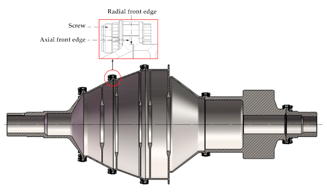
  • The distributed and calibrated angles of the mounting screw holes of each rotor were not considered in the existing assembly error propagation models;
  • It is unreasonable to equate the assembly datum for optimizing the unbalance with that for optimizing the coaxiality;
  • Heuristic algorithm should be applied to searching for the optimal mounting angles of the rotors at each stage in the process of the synchronous optimization of the coaxiality and unbalance.
In order to solve the above problems, an assembly method for a multistage rotor of an aero-engine is proposed to synchronously optimize the coaxality and unbalance in this paper. In 
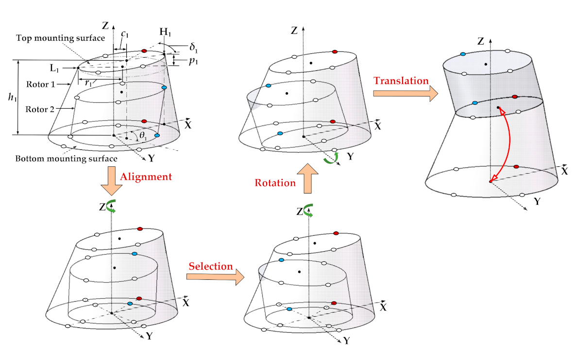
Section 2.1, we developed a coordinate transmission model to predict the coordinates of any points in the rotors at each stage after assembly. In Section 2.2, we proposed two different assembly optimization data for the coaxiality and unbalance, and established a dual objective evaluation function of that. In Section 3, the synchronous optimization for the coaxiality and unbalance was achieved by using a genetic algorithm, and the effectiveness of the proposed assembly optimization method was verified by the simulations and experiments. In addition, the Monte Carlo simulations based on normally distributed random variables are performed to assess the performance of the proposed optimization method.

2. Methods

2.1. Coordinate Transmission Model

The rotors at each stage of a multistage rotor of an aero-engine are assembled step-by-step through their own “assembly rabbet”, and connected by a certain number of screws. The “assembly rabbet” can be interpreted as the stop structure of the opening, also known as the radial and axial front edge as shown in Figure 1. The concentricity and parallelism errors of the top and bottom mounting surfaces of each rotor formed in the manufacturing process are continuously propagated through these “tolerance guide elements”. Furthermore, the actual spatial locations of the rotors at each stage are deviated from their ideal nominal locations after assembly. The centroid and the center-of-mass of the rotors at each stage also deviate from the ideal assembly axis, thus forming the accumulative errors of the coaxiality and unbalance of the whole assembly. A coordinate transmission model used for predicting the coordinates of the centroid and center-of-mass of the rotors at each stage after assembly is derived in this section.
Considering the existence of the geometrical deviation of the mounting surfaces of each rotor, the assembly processes of a two-stage simulated rotor are first analyzed. In addition, the distributed and calibrated angles of the mounting screw holes were taken into account. As shown in Figure 2, the centroid of the bottom mounting surfaces of each rotor is selected as the origin of the coordinate system during geometric measurement. In addition, the bottom mounting surface of Rotor-1 is used as the xy-plane of the coordinate system for assembly. c1 and p1 refer to the concentricity and parallelism errors of Rotor-1, respectively. θ1 refers to the eccentric angle of the centroid of the top mounting surface of Rotor-1. H1 and L1 refer to the highest and lowest points of the mounting surface of Rotor-1, respectively, which are fitted when measuring the parallelism error. δ1 refers to the calibrated angle between the highest point and the calibrated screw hole of Rotor-1. The red and blue dots in Figure 2 are the calibrated screw holes of Rotor-1 and Rotor-2, respectively, and all the hollow dots on the top and bottom mounting surfaces refer to the uniform distributed screw holes. h1 is the measured distance between the top and bottom mounting surface of Rotor-1, and r1 is the measured radius of the top mounting surface of Rotor-1. The subscripts of the above parameters represent the stage of each rotor, and all the parameters of the rotors at different stages can be expressed by changing these subscripts. Furthermore, the assembly processes of the two-stage rotor can be presented as follows:
1.
Alignment of the mounting screw holes of the adjacent rotors
A pair of mounting screw holes of each rotor is set as the calibrated screw holes used for aligning during assembly. Rotor-1 is stationary by default, and aligning the calibrated screw holes of Rotor-1 and Rotor-2 by rotating the Rotor-2 around the z-axis. The number of the mounting screw holes of the adjacent rotors can be different, but at least make the distributed angles of one pair of mounting screw holes in the top and bottom mounting surfaces of a rotor the same.
2.
Selection of the assembly angles of the rotors at each stage
After alignment, the assembly angle of Rotor-2 can be selected on the discrete angles with the mounting screw holes existing. That is, rotating Rotor-2 around the z-axis with a quantitative distributed angle to select an optimal assembly angle. It can be represented by the matrix Tz2 as shown in Equation (1),
T z 2 = cos 360 k 2 q 2 + δ 2 δ 1 sin 360 k 2 q 2 + δ 2 δ 1 0 sin 360 k 2 q 2 + δ 2 δ 1 cos 360 k 2 q 2 + δ 2 δ 1 0 0 0 1 ,
where q2 refers to the number of the uniform distributed screw holes on the mounting surface of the rotor at second stage, and k2 is the number of the distributed angles of the mounting screw holes of Rotor-2 rotating around the z-axis relative to Rotor-1.
3.
Rotating to make the corresponding mounting surfaces parallel
The x-axis is formed by a projection, on the xy-plane, of a line connecting H1 and L1. The y-axis is perpendicular to the x-axis. Rotating Rotor-2 with an angle of (p1/2r1) around the y-axis, so that the bottom mounting surface of Rotor-2 is parallel to the top mounting surface of Rotor-1. This rotation matrix can be expressed as in Equation (2).
T y 1 = cos arctan p 1 2 r 1 0 sin arctan p 1 2 r 1 0 1 0 sin arctan p 1 2 r 1 0 cos arctan p 1 2 r 1 .
4.
Translating to make the centroid of the corresponding mounting surfaces coincide
Stacking Rotor-2 on Rotor-1 to make the centroid of the bottom mounting surface of Rotor-2 coincide with that of the top mounting surface of Rotor-1. The coordinate vector of any point in Rotor-2 after assembly can be obtained by the following equation:
A 2 = A 2 T z 2 T y 1 + A 1 ,
where A2′ refers to the coordinate vector of any point in Rotor-2 after assembly, A2 to that before assembly. A1 is the coordinate vector of the centroid of the top mounting surface of Rotor-1, which can be expressed as in Equation (4):
I 1 = c 1 cos θ 1 c 1 sin θ 1 h 1 .
Furthermore, the assembly processes of an n-stage rotor can be divided into those of (n−1) two-stage rotors. Firstly, the coordinate transmission of the rotors in the last two stages during assembly is calculated, and these two assembled rotors are regarded as a whole and assembled with the rotor at antepenultimate stage, and so on, the coordinate transmission model of the assembly processes of an n-stage rotor can be expressed as in Equation (5):
A n = A n n : 1 : 2 T z n T y n 1 + A n 1 n N , n > 1 .

2.2. Optimization Datum for the Coaxiality and Unbalance

2.2.1. Table-Axis for Optimizing the Coaxiality

As shown in Figure 3, the table-axis is a fixed normal axis passing through the origin of the measuring coordinate system and perpendicular to the measuring datum plane, which does not change with the change of the assembled states of a multistage rotor. It has been proved to be the most effective optimization datum for the coaxiality of a multistage rotor during assembly in current studies [12,13,14,15,16,17,18]. Due to the transmission and accumulation of the geometric errors of each single-stage rotor in the assembly process, the initial concentricity errors of each rotor change after assembly. By comparing the concentricity errors of each rotor after assembly, the maximum value is taken to represent the coaxiality of a multistage rotor, and minimizing this maximum value, then the single-objective optimization function for the coaxiality of a multistage rotor can be expressed as in Equation (6):
C n = min max c 1 , c 2 , ... , c n n N , n > 1 ,
where cn′ refers to the concentricity error of the rotor at nth stage after assembly, which can be calculated by Equation (7):
c n = I n x 2 + I n y 2 ,
where In(x) and In(y) refer to the values of the x and y-coordinate of the centroid of the top mounting surface of the rotor at nth stage after assembly, respectively. They can be be obtained by substituting In(x) and In(y) into Equation (5).

2.2.2. Axis of Rotation for Optimizing the Unbalance

The assembly datum for optimizing the unbalance of a multistage rotor in the existing assembly methods [23,24] are all used as that for optimizing the coaxiality, namely, table-axis. In addition, the calculation of the unbalance or the offset of the center-of-mass of the rotor is based on table-axis, which goes against to the definition of the unbalance. In fact, the unbalance refers to the product of the unbalanced mass and its action radius, or the product of the mass and the offset of the center-of-mass of the rotor. The calculation of the action radius and the offset of the center-of-mass should be based on the actual axis of rotation of the rotor, not the geometric measurement datum.
Before the final assembly of the multistage rotors of an aero-engine, the measurement and elimination of the unbalance should be carried out on the dynamic balancing machine. Figure 4 shows a simplified structure of the supporting form in the dynamic balancing test. The front and rear journals of the rotor are placed on the supports at both ends of the dynamic balancing machine and supported by double rollers, which plays an automatic centering role, that is, the rotor rotates around the connecting line between the centers of the front and rear journals. The unbalance mass and its action radius measured by the dynamic balancing machine are also calculated relative to this axis of rotation. Therefore, the assembly optimization of unbalance must be based on this axis.
In general, the rotor at first stage and the rotor at last stage are usually the parts with journal, and the center of the journal of the rotor at first stage will also be used as the coordinate origin in the measurement and assembly. As shown in Figure 3, the axis of rotation of the two-stage rotor is the connecting line between the origin of the bottom datum surface and the center of the top mounting surface, which is consistent with the axis of rotation in the actual dynamic balancing test. Therefore, this axis is used as the assembly datum for optimizing the unbalance of a multistage rotor in this study, and the action radii of the unbalanced masses of the rotors at each stage are calculated relative to it. In Figure 3, m1 and m2 refer to the unbalanced mass of Rotor-1 and Rotor-2, respectively. e1′ and e2′ refer to the action radii of m1 and m2, respectively. A linear parametric equation can be used to express this axis of rotation shown in Equation (8):
x = I n x λ n y = I n y λ n z = I n z λ n ,
where λn is the parameter of the linear equation of the axis of rotation in the assembled state of the rotor at nth stage, and (In(x), In(y), In(z)) refers to the coordinate of the centroid of the top mounting surface of the rotor at nth stage after assembly. Furthermore, a plane equation with this axis of rotation as the normal axis and passing through the unbalanced mass point of the rotor at nth stage can be expressed as in Equation (9):
I n x x Z n x + I n y y Z n y + I n z z Z n z = 0 ,
where (Zn(x), Zn(y), Zn(z)) refer to the coordinate of the unbalanced mass point of the rotor at nth stage after assembly. It can be obtained by substituting the known coordinate vector of the unbalanced mass point of the rotor at nth stage before assembly into Equation (5). Furthermore, by substituting x, y, and z in Equation (8) into Equation (9), λn is acquired in Equation (10):
λ n = I n x Z n x + I n y Z n y + I n z Z n z I n x 2 + I n y 2 + I n z 2 .
Moreover, by substituting λn into Equation (8), the coordinate of the intersection point (Snx, Sny, Snz,) of the axis of rotation and the plane in Equation (9) can be obtained as in Equation (11):
{ S n x = I n x 2 Z n x + I n x I n y Z n y + I n x I n z Z n z I n x 2 + I n y 2 + I n z 2 S n y = I n x I n y Z n x + I n y 2 Z n y + I n y I n z Z n z I n x 2 + I n y 2 + I n z 2 S n z = I n x I n z Z n x + I n y I n z Z n y + I n z 2 Z n z I n x 2 + I n y 2 + I n z 2
Furthermore, the action radius of the unbalanced mass of the rotors at nth stage can be calculated by Equation (12):
e n = S n x Z n x 2 + S n y Z n y 2 + S n z Z n z 2 .
Here, the unbalance of the rotor at nth stage can be expressed as Equation (13):
u n = m n e n .
Furthermore, according to the principle of the balance of couples, the unbalance of the rotors at each stage are decomposed into the pre-set balancing surfaces L and R through Equation (14) below:
u L = i = 1 n l R l i l R l L u i u R = i = 1 n l i l L l R l L u i ,
where uL and uR are the unbalance in the balancing surfaces L and R, respectively. lL and lR are the vertical distances between the supporting point and the balancing surfaces L and R, respectively. By comparing uL and uR, and minimizing the maximum value between them, then the single-objective optimization function for the unbalance of a multistage rotor can be expressed as in Equation (15):
U n = m i n m a x u L , u R n N * , n > 1 .

2.2.3. Dual Objective Evaluation Function for the Coaxiality and Unbalance

Specific to a multi-objective optimization problem, it is difficult to obtain the optimal solutions simultaneously for all the objective functions. In other words, no optimal solution can be obtained, enabling all the objective functions to reach their own optimal values. However, if the objective functions can approach their own ideal values to the greatest extent, a comparatively satisfactory non-inferior solution may be obtained. On this basis, a multi-objective optimization problem can be transformed into an issue of solving extremums of a unified evaluation function. In addition, a weight coefficient Wn can be introduced, making each single-objective function dimensionless. Based on the above theory, a dual objective evaluation function for the coaxiality and unbalance of a multistage rotor after assembly is established as in Equation (16):
V min F x = W 1 C n x C n * 2 + W 2 U n x U n * 2 s . t .   x = k 1 , k 2 , , k n , k n 0 , 0.5 q n q n N * , q n 1 ,
where qn refers to the number of the uniform distributed screw holes on the mounting surfaces of the rotor at nth stage. The design variable x represents a vector formed by the number (kn) of the intervals of the mounting screw holes of the rotor at the nth stage rotating around the z-axis relative to the rotor at (n−1)th stage. In addition, kn is a discrete variable that varies from 0 to 0.5qn, which means that the assembly angles of the rotors at each stage varies from 0 to 180°. Cn and Un refer to the minimum values of the coaxiality and unbalance of a n-stage rotor, respectively. W1 and W2 refer to the weight coefficients of the coaxiality and unbalance, and W1 = 1/Cn and W2 = 1/Un. Such an evaluation function can make the double objective of the coaxiality and unbalance dimensionless, which not only considers that each objective is as close to their optimal value as possible, but also reflects that both objectives are equally important to the entire dual objective optimization.

2.3. Genetic Algorithm

Genetic algorithm (GA) is a kind of heuristic algorithm, which is a method to search the optimal solution by simulating the natural evolution process. This algorithm transforms the process of solving the problem into a process similar to the crossover and mutation of chromosome genes in biological evolution by means of mathematics and computer simulation. When solving complex combinatorial optimization problems, compared with some conventional optimization algorithms, they usually can get better optimization results quickly [26]. In this section, the dual objective evaluation function for the coaxiality and unbalance proposed in Section 2.2.3 is further developed to a fitness function of GA as in Equation (17):
f i t n e s s _ G x = 1 / F ( x ) s . t .   x = k 1 , k 2 , , k n , k n 0 , 0.5 q n q n N , q n 1 .
When the fitness function reaches the maximum value, the dual objective evaluation function for the coaxiality and unbalance can reach the minimum value. The optimization process of the population with regard to the assembly angles of the rotors at each stage is presented in Figure 5. First, kn is regarded as a gene, so that a n-stage rotor corresponds to n genes. These n genes are combined into a chromosome. In the optional range of kn, an initialization population with 1000 chromosomes is randomly generated. Then, the fitness of all chromosomes is calculated, the best chromosome is retained, and then the fitness of the other chromosomes is calculated after the mutation and crossover. The chromosome with the worst fitness is eliminated, and the remaining chromosomes are mixed with the previously retained chromosomes with the optimal fitness to form a new population for the next iteration until the termination conditions are satisfied and the optimal solution is obtained.

3. Results

3.1. Simulation

3.1.1. Model and Parameters

As shown in Figure 6, a simplified four-stage high-pressure rotor system of an aero-engine is used to investigate the effectiveness of the dual objective evaluation function for the coaxiality and unbalance. The high-pressure rotor system consists of four components: the front axle, the compressor, the turbine and the rear axle, which is assembled stage-by-stage through the radial and axial front edges, and tightly connected by uniform distributed hexagon socket head cap screws (M3 with a thread length of 12 mm).
The setup of the geometric parameters (cn, θn, pn, rn, hn, δn, qn) of the rotors at each stage is shown in Table 1. The distances (lL and lR) between the supporting point and the pre-set balancing surfaces L and R, are 97.5 mm and 341.5 mm, respectively. The four M3 screws with thread length of 20 mm are artificially used to replace the four M3 screws with thread length of 12 mm at the calibrated screw holes of rotors at each stage, in order to produce four unbalanced masses of 0.8 g. In Table 2, the coordinates of the unbalanced mass points in the local measuring coordinate system of the front axle (O1(x, y, z)), the compressor (O2(x, y, z)), the turbine (O3(x, y, z)), and the rear axle (O4(x, y, z)) are measured by the 3D drawing software SOLIDWORKS.

3.1.2. Genetic Optimization

The front axle, the compressor, the turbine, and the rear axle are defined as Rotor-1, Rotor-2, Rotor-3, and Rotor-4, respectively. In terms of the front axle (Rotor-1), its assembly angle is 0° by default. Each chromosome is designed to hold three genes, which is (k2, k3, k4). The genetic optimization of kn is carried out for three times, respectively, based on the single-objective function for the coaxiality, the single-objective function for the unbalance, and the dual objective function for the coaxiality and unbalance.
The convergence progress of the single-objective optimization for the coaxiality is shown in Figure 7, and the optimal fitness of the coaxiality reaches 0.0406 mm; meanwhile, the corresponding unbalance reaches 43.8301 g·mm (Table 3). The convergence progress of the single-objective optimization for the unbalance is shown in Figure 8, and the optimal fitness of the unbalance reaches 12.3963 g·mm; meanwhile, the corresponding coaxiality reaches 0.0654 mm (Table 3). The convergence progress of the dual objective optimization for the coaxiality and unbalance is shown in Figure 9, the coaxiality and unbalance corresponding to the optimal dimensionless fitness of F(x) reaches 0.0524 mm and 12.6506 g·mm, respectively. From Figure 7, Figure 8 and Figure 9, it can be seen that all the convergence processes for the above three optimization objects have a good convergence within 200 iterations.
As shown in Figure 10, the unbalance obtained by the optimization for the dual objective is almost the same as that obtained by the optimization for the single-objective of the unbalance. In addition, compared with the coaxiality obtained by the optimization for the single-objective of the coaxiality, and that obtained by the optimization for dual objective is increased by 19.9%. However, the coaxiality obtained by the optimization for the dual objective is increased by 29.1% compared with that obtained by the optimization for the single-objective of the coaxiality, but the unbalance is reduced by 71.1%. Clearly, the simulation results show that the genetic optimization for the dual objective has the potential to preferably realize synchronous optimization of the coaxiality and unbalance.

3.1.3. Monte Carlo Simulation

A real four-stage rotor for experimental verification is machined according to the nominal dimensions of the high-pressure rotor system proposed in Section 3.1.1. The tolerance design of the four-stage rotor follows the ISO standards on tolerancing (ISO GPS 1101-2017). All the dimensional and geometric tolerances of the rotors at each stage are controlled within 0.02 mm, and all the positional tolerances of the mounting screw holes are controlled within 0.05 mm as far as possible. Figure 11 shows the measured actual scene and schematic diagram of the front axle. The measuring principles of the compressor, the turbine and the rear axle are the same as that of the front axle. Considering that the actual measurement errors may lead to the instability of the genetic optimization results, all geometric parameters of the rotor at each stage are measured ten times at the same measurement conditions. The measurement results are shown in Table A1, Table A2, Table A3 and Table A4, and the mean values and the standard deviation of all the parameters of the four-stage rotor are calculated in Table 4. All the measured geometric parameters of the four-stage rotor are assumed to have a normal distribution with their own mean values and standard deviations. Each assembly optimization procedure is simulated 10,000 times by using a standard Monte Carlo method.
Furthermore, the three simulations in Section 3.1.2 are repeated by using the Monte Carlo method. As shown in Figure 12, the optimal assembly angles of the compressor, the turbine and the rear axle are 60°, 135° and 90° in the 10,000 times dual objective optimizations, respectively. In addition, the corresponding numbers (kn) of the distributed angles of the mounting screw holes of each rotor rotating relative to the next rotor are 1, 12 and 0, respectively. It can be seen that the geometric measured errors of the rotors at each stage has no effect on the optimal solutions in the 10,000 times simulations. Moreover, the optimal assembly angles of the other two single-objective optimizations are shown in Figure 13 and Figure 14, respectively, and the coaxiality and unbalance corresponding to the optimal solutions are presented in Table 5.

3.2. Experiment

The optimal assembly angles of each rotor of the high-pressure rotor system in the Monte Carlo simulation of the single-objective optimization for the coaxiality, and that for the unbalance, and the dual objective optimization were obtained in Section 3.1.3. Furthermore, the real machined four-stage rotor was assembled stage-by-stage according to the three groups of the optimal assembly angles in Table 5, respectively. From Figure 15, the coaxiality and unbalance of the assembled high-pressure rotor system were measured by a 3D coordinate measuring instrument manufactured by Carl Zeiss AG (Jena, Germany) and a dynamic balancing machine manufactured by Shanghai Shenzhong Co., Ltd. (Shanghai, China), respectively. In addition, all the unbalance measurements were carried out at the same rotational speed (1000 rpm). The coaxiality and unbalance of the four-stage rotor under the three different assembled states were measured six times (Table A5), respectively, and the mean value and the standard uncertainty of that are presented in Table 6.
As shown in Table 6, the coaxiality achieved by the dual objective optimization increases by 45.2% if compared with that generated by the single-objective optimization for the coaxiality; however, the unbalance reduces by 61.8% accordingly. The coaxiality and unbalance thus achieved by the dual objective optimization reduces and increases by 66.4% and 27.5%, respectively, in comparison with those produced by the single-objective optimization for the unbalance. Moreover, by comparing the results in Table 5 and Table 6, there are small differences between the measured values and the theoretical values of the coaxiality and unbalance, which may be caused by the wear and tear of the front edge of the rotors in the repeated assembly.
However, there is a common phenomenon in the experiment and simulation, that is, the coaxiality obtained by the dual objective optimization is higher than that obtained by the single-objective optimization for the coaxiality, but the unbalance is reduced greatly. In the same way, compared with the single-objective optimization for the unbalance, and that of the dual objective optimization is increased, but the coaxiality is reduced greatly. Therefore, it is revealed that the proposed double-objective optimization by using the genetic algorithm is capable of realizing the synchronous optimization of the coaxiality and unbalance of a real four-stage rotor.

4. Discussion

In this section, we summarized three main works in this study and discuss the innovation of that compared with the existing studies. In addition, ideas about the future work were proposed.
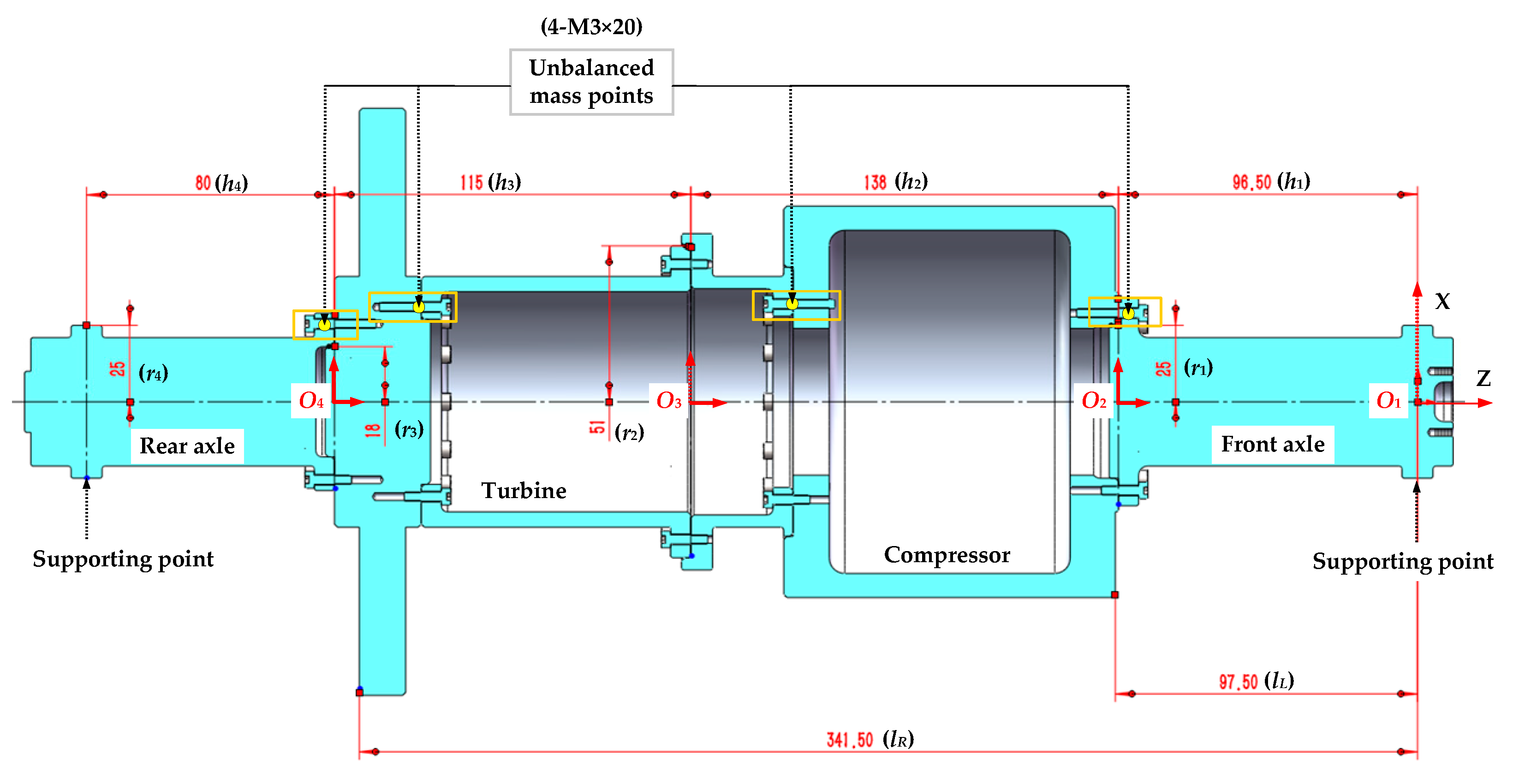
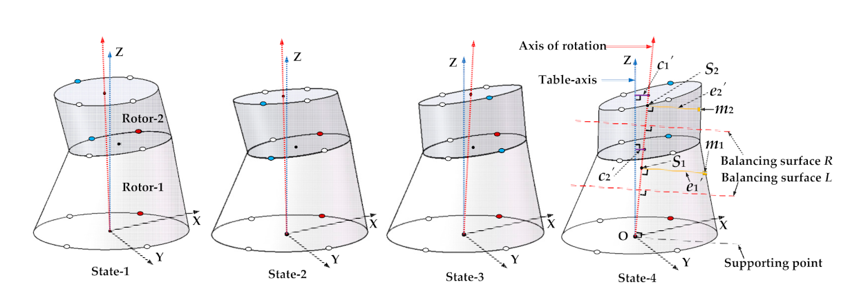
For the first problem raised in the Introduction, we put forward the alignment process of the mounting screw holes of the adjacent rotors during the initial assembly, which is very important to the selection of the initial assembly angles of the rotors at each stage. Then, the distributed and calibrated angles of the mounting screw holes of the rotors at each stage are introduced into the coordinate transmission model. In this way, the optional assembly angles of rotors at each stage are the discrete variables formed by the multiples of the distributed angles of the mounting screw holes, which is completely consistent with that in the actual assembly. However, the assembly angles of each rotor were the continuous variables in the existing studies. It did not explain how to determine the initial assembly angles of each rotor after alignment, and did not give the exact relationship between the geometric parameters and the calibrated screw holes.
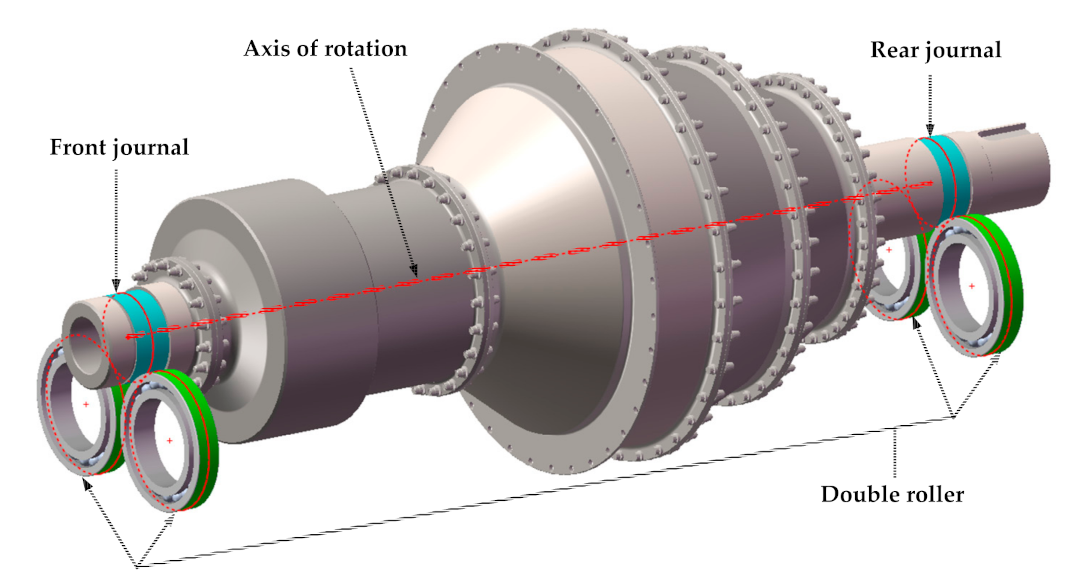
For the second problem raised in the Introduction, we proposed an assembly datum to be used for optimizing the unbalance, which is different from that for optimizing the coaxiality. The unbalance in two-plane measured by a dynamic balancing machine must be perpendicular to the axis of rotation of the measured rotor. Such an axis of rotation is just a line connecting the centroid of the journals of the front and rear axles. Therefore, this axis should be used as the assembly datum for optimizing the unbalance to ensure that the experimental conditions are consistent with the simulation conditions. However, the optimization datum for the unbalance was equated with that for the coaxiality in the current studies.
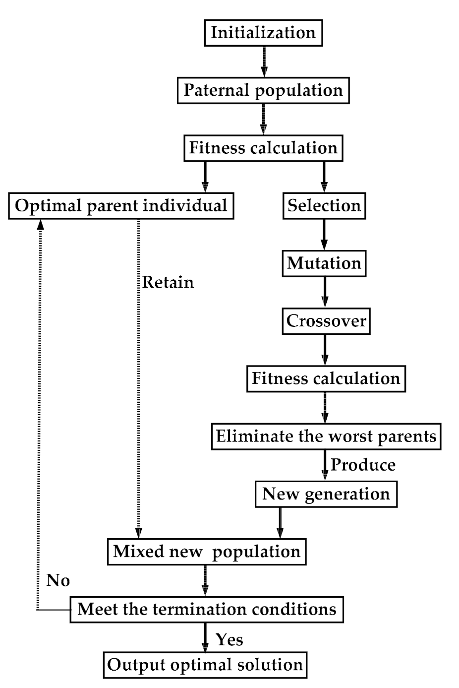
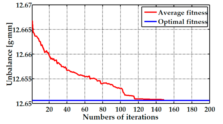
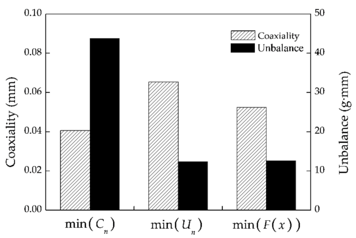
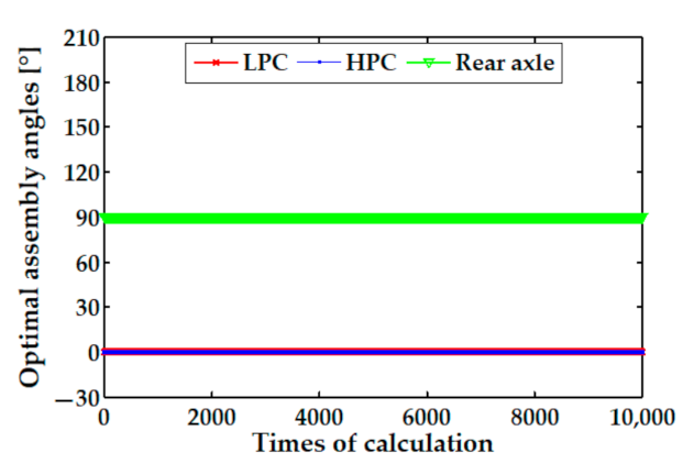
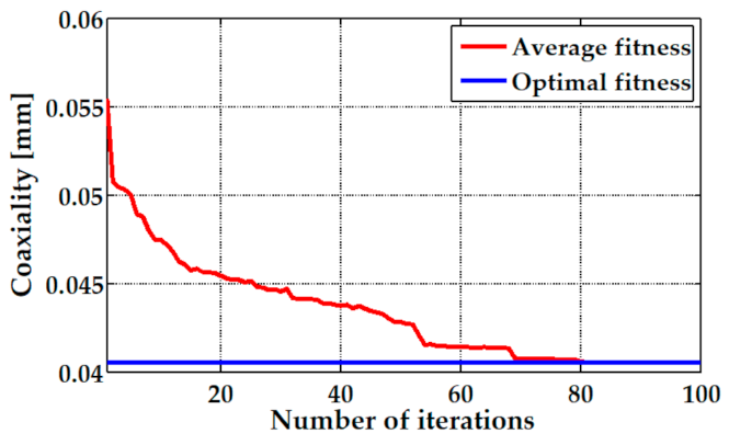
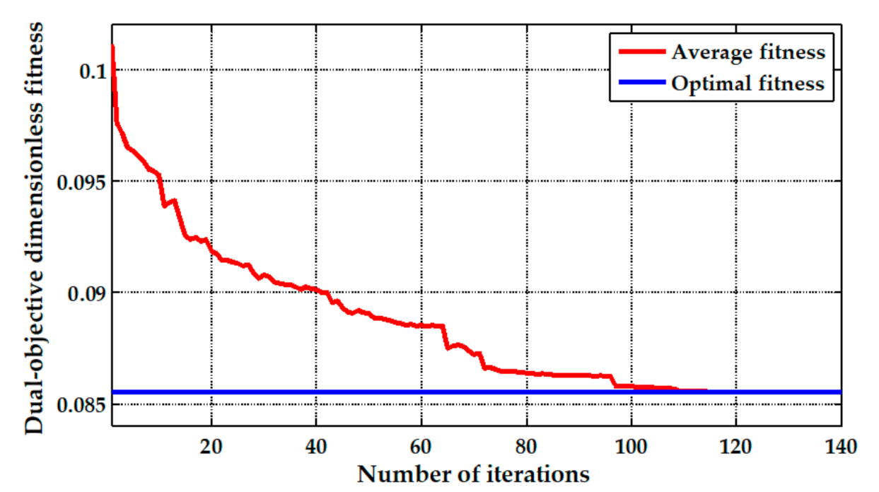
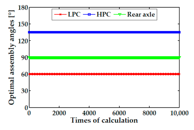
For the third problem raised in the Introduction, we proposed a dual objective optimization model by using a genetic algorithm to achieve the synchronous minimization of the coaxiality and unbalance of a multistage rotor. The simulation results show that the optimization processes of the single-objective and the dual objective optimization all had a good convergence. Furthermore, the influence of the measurement errors on the stability of the genetic optimization was also investigated by using a Monte Carlo method.
Our future work plan is to combine the coordinate transmission model proposed in this paper with the rotor dynamics equation, and use the finite element method to investigate the influence of the changes of the displacements of nodes and the unbalance on vibration of a multistage rotor of an aero-engine in the flexible state of the high-speed operation. Furthermore, we will take the vibration of the key node in the high pressure rotor system as the optimization objective and calculate the optimal assembly angles of rotors at different stages.

5. Conclusions

In this study, we proposed an assembly method based on the dual objective synchronous optimization for the coaxality and unbalance, which is applicable to the turbofan aero-engine with multistage rotors. The main contributions of this study can be summarized as follows:
  • A coordinate transmission model was developed to calculate the coordinates of any points in the rotors at each stage during the assembly processes of a multistage rotor. It can be used to predict the coaxality and unbalance of a multistage rotor.
  • A time-varying axis of rotation was calculated to be the assembly optimization datum for the unbalance of a multistage rotor. It is more in line with the actual conditions of the dynamic balancing test.
  • The synchronous optimization for the coaxality and unbalance of a multistage rotor was realized by using a genetic algorithm, and the optimal result is not affected by the geometric measured errors of the rotors at each stage.

Author Contributions

Conceptualization, Y.C. and J.C.; methodology, Y.C.; software, Y.C.; validation, Y.C.; formal analysis, Y.C.; investigation, Y.C.; resources, J.C.; data curation, Y.C.; writing—original draft preparation, Y.C.; writing—review and editing, Y.C.; visualization, Y.C.; supervision, X.S.; project administration, J.C.; funding acquisition, J.C. All authors have read and agreed to the published version of the manuscript.

Funding

This research was funded by the Outstanding Youth Project of Natural Science Foundation of Heilongjiang Province, Grant JQ2019E002. The authors are grateful for the financial support.

Institutional Review Board Statement

Not applicable.

Informed Consent Statement

Not applicable.

Data Availability Statement

Not applicable.

Acknowledgments

The authors acknowledge Shihai Cui in the College of Mechanical Engineering, Tianjin University of Science and Technology for the active support of the research.

Conflicts of Interest

The authors declare no conflict of interest.

Abbreviations

AbbreviationsMeaning
GAGenetic algorithm
2DTwo-dimensional
3DThree-dimensional

Symbols

SymbolsMeaning
cnConcentricity error of the rotor at nth stage
pnParallelism error of the rotor at nth stage
θnEccentric angle of the rotor at nth stage
HnHighest point of the rotor at nth stage
LnLowest point of the rotor at nth stage
δnCalibrated angle of the calibrated screw hole of the rotor at nth stage
hnDistance between the top and bottom mounting surface of the rotor at nth stage
rnMeasured radius of the top mounting surface of the rotor at nth stage
qnNumber of the uniform distributed screw holes on the mounting surface of the rotor at nth stage
knNumber of the distributed angles of the mounting screw holes of the rotor at nth stage rotating around the z-axis relative to the rotor at (n−1)th stage
AnCoordinate vector of any point in the rotor at nth stage after assembly
AnCoordinate vector of any point in the rotor at nth stage before assembly
cnthe concentricity error of the rotor at nth stage after assembly
CnSingle-objective optimization function for the coaxiality of a n-stage rotor
In(x)Value of the x-coordinate of the centroid of the top mounting surface of the rotor at nth stage after assembly
In(y)Value of the y-coordinate of the centroid of the top mounting surface of the rotor at nth stage after assembly
In(z)Value of the z-coordinate of the centroid of the top mounting surface of the rotor at nth stage after assembly
In(x)Value of the x-coordinate of the centroid of the top mounting surface of the rotor at nth stage before assembly
In(y)Value of the y-coordinate of the centroid of the top mounting surface of the rotor at nth stage before assembly
In(z)Value of the z-coordinate of the centroid of the top mounting surface of the rotor at nth stage before assembly
TznMatrix of rotation of the rotor at nth stage about z-axis relative to the rotor at (n−1)th stage
TynMatrix of rotation of the rotor at nth stage about y-axis relative to the rotor at (n−1)th stage
mnUnbalanced mass of the rotor at nth stage
enAction radius of mn
λnParameter of the linear equation of the axis of rotation in the assembled state of the rotor at nth stage
Zn(x)Value of the x-Coordinate of the unbalanced mass point of the rotor at nth stage after assembly
Zn(y)Value of the y-Coordinate of the unbalanced mass point of the rotor at nth stage after assembly
Zn(z)Value of the z-Coordinate of the unbalanced mass point of the rotor at nth stage after assembly
SnxValue of the x-Coordinate of the intersection point
SnyValue of the y-Coordinate of the intersection point
SnzValue of the z-Coordinate of the intersection point
uLUnbalance in the balancing surfaces L
uRUnbalance in the balancing surfaces R
lLVertical distances between the supporting point and the balancing surfaces L
lRVertical distances between the supporting point and the balancing surfaces R
WnWeight coefficient
CnMinimum values of the coaxiality of a n-stage rotor
UnMinimum values of the unbalance of a n-stage rotor

Appendix A

Table A1. The measured geometric parameters of the front axle.
Measurement Sequencec1 [mm]θ1 [°]p1 [mm]r1 [mm]h1 [mm]δ1 [°]
10.009620.70.016625.010596.549178.1
20.010221.40.016825.009996.549878.1
30.010321.20.017925.010196.550078.4
40.010621.50.016525.011496.548878.2
50.009821.90.016825.010996.550377.7
60.009520.70.016525.010696.550378.8
70.010521.30.016925.009396.549678.6
80.010121.20.016625.010396.550478.1
90.009621.90.017825.010996.551378.6
100.009822.90.017325.010996.549778.4
Table A2. The measured geometric parameters of the compressor.
Measurement Sequencec2 [mm]θ2 [°]p2 [mm]r2 [mm]h2 [mm]δ2 [°]
10.0193114.60.018851.0894138.0393190.9
20.0189113.10.018751.0905138.0397190.6
30.0192114.50.019351.0894138.0414190.9
40.0188114.00.019251.0899138.0392191.1
50.0191112.50.019151.0903138.0400191.2
60.0194113.70.019151.0897138.0395190.8
70.0183113.50.019051.0910138.0407191.4
80.0184115.30.018751.0911138.0419191.5
90.0184113.80.019251.0903138.0392190.8
100.0193114.60.018751.0898138.0406191.6
Table A3. The measured geometric parameters of the turbine.
Measurement Sequencec3 [mm]θ3 [°]p3 [mm]r3 [mm]h3 [mm]δ3 [°]
10.0214158.50.020518.0097114.929835.6
20.0205159.00.020818.0102114.930335.6
30.0211157.70.020718.0100114.928835.1
40.0203158.10.020818.0102114.931235.2
50.0210158.70.020818.0104114.929635.5
60.0216158.20.021218.0097114.930035.5
70.0213158.80.020718.0112114.929635.0
80.0210158.40.020718.0106114.929835.9
90.0209158.40.021018.0097114.930235.6
100.0212158.30.021418.0093114.929735.5
Table A4. The measured geometric parameters of the rear axle.
Measurement Sequencec4 [mm]θ4 [°]p4 [mm]r4 [mm]h4 [mm]δ4 [°]
10.019572.90.010524.999880.0120113.6
20.020571.40.011225.000080.0098113.2
30.020174.30.011125.000580.0095114.0
40.019772.70.011024.999780.0096113.7
50.020473.40.010924.999980.0099113.4
60.020071.80.011724.999680.0106113.8
70.020073.50.010925.001280.0103113.5
80.020172.70.010925.000180.0092113.4
90.020372.60.010724.999280.0107113.3
100.020573.30.010724.999880.0092113.5
Table A5. Six times measurement results of the coaxiality and unbalance of the high-pressure rotor system.
Optimization ObjectiveMeasurement SequenceCn [mm]Un [g·mm]
min (Cn)10.027648.6874
20.028448.8419
30.027349.1017
40.028948.8939
50.028448.9469
60.027848.7567
min (Un)10.122018.8190
20.120618.6926
30.121518.5424
40.121518.4549
50.122618.6685
60.121518.9537
min (F(x))10.041623.8936
20.040423.9983
30.041323.6513
40.040723.6226
50.040423.8729
60.040223.9149

References

  1. Sun, W.; Li, T.; Yang, D. Dynamic investigation of aeroengine high pressure rotor system considering assembly characteristics of bolted joints. Eng. Fail. Anal. 2020, 112, 104510. [Google Scholar] [CrossRef]
  2. Wang, S.W.; Mo, R.; Yang, H.C. Quantitative and meticulous methods to aero-Engine assembly Process. Appl. Mech. Mate. 2012, 220–223, 206–209. [Google Scholar] [CrossRef]
  3. Zhang, M.; Liu, Y.; Sun, C. Measurements error propagation and its sensitivity analysis in the aero-engine multistage rotor assembling process. Rev. Sci. Instrum. 2019, 90, 115003. [Google Scholar] [CrossRef] [PubMed]
  4. Dal, A.; Karaay, T. Effects of angular misalignment on the performance of rotor-bearing systems supported by externally pressurized air bearing. Tribol. Int. 2017, 111, 276–288. [Google Scholar] [CrossRef]
  5. Huang, Z.; Zhou, J.; Yang, M. Vibration characteristics of a hydraulic generator unit rotor system with parallel misalignment and rub-impact. Arch. Appl. Mech. 2011, 81, 829–838. [Google Scholar] [CrossRef]
  6. Desouki, M.; Sassi, S.; Renno, J. Dynamic response of a rotating assembly under the coupled effects of misalignment and imbalance. Shock. Vib. 2020, 1, 1–26. [Google Scholar] [CrossRef]
  7. Chen, Y.; Cui, J.; Sun, X. An unbalance optimization method for a multi-stage rotor based on an assembly error propagation model. Appl. Sci. 2020, 11, 887. [Google Scholar] [CrossRef]
  8. Ding, S.; Sun, J. Multistage rotational optimization using unified Jacobian–Torsor model in aero-engine assembly. Proc. Inst. Mech. Eng. Part B J. Eng. Manuf. 2019, 233, 251–266. [Google Scholar] [CrossRef]
  9. Whitney, D.; Gilbert, O.; Jastrzebski, M. Representation of geometric variations using matrix transforms for statistical tolerance analysis in assemblies. Res. Eng. Des. 1994, 6, 191–210. [Google Scholar] [CrossRef]
  10. Mantripragada, R.; Whitney, D. Modeling and controlling variation propagation in mechanical assemblies using state transition models. IEEE. Robot. Autom. Mag. 1999, 15, 124–140. [Google Scholar] [CrossRef]
  11. Kenneth, W.; Spencer, P. Tolerance analysis of 2-d and 3-d mechanical assemblies with small kinematic adjustments. Adv. Toler. Tech. 2004, 218, 1869–1873. [Google Scholar]
  12. Hussain, T.; Yang, Z.; Popov, A.A. Straight-build assembly optimization: A method to minimize stage-by-stage eccentricity error in the assembly of axisymmetric rigid components (two-dimensional case study). J. Manuf. Sci. Eng. 2011, 133, 031014. [Google Scholar] [CrossRef]
  13. Hussain, T.; Mcwilliam, S.; Popov, A.A. Geometric error reduction in the assembly of axis-symmetric rigid components: A two-dimensional case study. Proc. Inst. Mech. Eng. Part B J. Eng. Manuf. 2012, 226, 1259–1274. [Google Scholar] [CrossRef]
  14. Hussain, T.; Yasinshaikh, G.; Shaikh, S.A. Variation propagation control in straight-build assemblies: 2d case study. Mehran Univ. Res. J. Eng. Technol. 2013, 32, 71–80. [Google Scholar]
  15. Yang, Z.; Hussian, T.; Popov, A.A. A comparison of different optimization techniques for variation propagation control in mechanical assembly. IOP Conf. 2011, 26, 012017. [Google Scholar] [CrossRef] [Green Version]
  16. Yang, Z.; Hussian, T.; Popov, A.A. Novel optimization technique for variation propagation control in an aero-engine assembly. Proc. Inst. Mech. Eng. Part B J. Eng. Manuf. 2010, 225, 100–111. [Google Scholar] [CrossRef]
  17. Yang, Z.; Popov, A.A.; Mcwilliam, S. Variation propagation control in mechanical assembly of cylindrical components. J. Manuf. Syst. 2012, 31, 162–176. [Google Scholar] [CrossRef] [Green Version]
  18. Yang, Z.; Popov, A.A.; Mcwilliam, S.; Hussian, T. Dimensional variation propagation analysis in straight-build mechanical assemblies using a probabilistic approach. J. Manuf. Syst. 2013, 32, 348–356. [Google Scholar] [CrossRef]
  19. Sun, J.; Ding, S.; Li, Z. Point-based solution using Jacobian-Torsor theory into partial parallel chains for revolving components assembly. J. Manuf. Syst. 2017, 46, 46–58. [Google Scholar]
  20. Sun, C.; Li, C.; Liu, Y. Prediction method of concentricity and perpendicularity of aero engine multistage rotors based on PSO-BP neural network. IEEE Access 2019, 7, 132271–132278. [Google Scholar] [CrossRef]
  21. Wang, L.; Sun, C.; Tan, J. Improvement of location and orientation tolerances propagation control in cylindrical components assembly using stack-build assembly technique. Assem. Autom. 2015, 34, 358–366. [Google Scholar] [CrossRef]
  22. Sun, Y.; Guo, J.; Hong, J. Repair decision based on sensitivity analysis for aero-engine assembly. Int. J Precis. Eng. Man. 2019, 20, 347–362. [Google Scholar] [CrossRef]
  23. Liu, Y.; Zhang, M.; Sun, C. A method to minimize stage-by-stage initial unbalance in the aero engine assembly of multistage rotors. Aerosp. Sci. Technol. 2018, 85, 270–276. [Google Scholar]
  24. Sun, C.; Liu, Z.; Liu, Y. An adjustment method of geometry and mass centers for precision rotors assembly. IEEE Access 2019, 7, 169992–170002. [Google Scholar] [CrossRef]
  25. Piskin, A.; Aktas, H.E.; Topal, A. Rotor balancing with turbine blade assembly using ant colony optimization for aero-engine applications. Int. J. Turbo Jet Engines 2017, 8, 0060. [Google Scholar] [CrossRef]
  26. Yang, X.S. Nature-Inspired Meta-Heuristic Algorithms; Luniver Press: Beckington, UK, 2008; pp. 314–322. [Google Scholar]
Figure 1. The section view of the drum-and-disk structure of a three-stage high pressure compressor (HPC) of an aero-engine.
Aerospace 08 00094 g001
Figure 2. The assembly processes of a two-stage simulated rotor.
Aerospace 08 00094 g002
Figure 3. The table-axis and the axis of rotation in the different assembled state of a two-stage rotor after assembly.
Aerospace 08 00094 g003
Figure 4. A simplified structure of the supporting form in the dynamic balancing test.
Aerospace 08 00094 g004
Figure 5. The optimization process of the genetic algorithm (GA).
Aerospace 08 00094 g005
Figure 6. The section view of a simplified four-stage high-pressure rotor system of an aero-engine.
Aerospace 08 00094 g006
Figure 7. The convergence progress of the single-objective optimization for the coaxiality based GA.
Aerospace 08 00094 g007
Figure 8. The convergence progress of the single-objective optimization for the unbalance based GA.
Aerospace 08 00094 g008
Figure 9. The convergence progress of the dual objective optimization for the coaxiality and unbalance based on GA.
Aerospace 08 00094 g009
Figure 10. The calculated coaxiality and unbalance of the high-pressure rotor system based on the three different optimization objectives.
Aerospace 08 00094 g010
Figure 11. The measurement of the geometric parameters of the front axle. (a) measured scene; (b) schematic diagram.
Aerospace 08 00094 g011
Figure 12. The optimal solution of the dual objective optimization in the 10,000 times simulations.
Aerospace 08 00094 g012
Figure 13. The optimal solution of the single-objective optimization for the coaxiality in the 10,000 times simulations.
Aerospace 08 00094 g013
Figure 14. The optimal solution of the single-objective optimization for the unbalance in the 10,000 times simulations.
Aerospace 08 00094 g014
Figure 15. The measurement of the coaxiality and unbalance of the assembled high-pressure rotor system. (a) The coaxiality is measured by a 3D coordinate measuring instrument; (b) The unbalance is measured by a dynamic balancing machine.
Aerospace 08 00094 g015
Table 1. The setup of the geometric parameters of the high-pressure rotor system.
Componentc [mm]θ [°]p [mm]r [mm]h [mm]δ [°]q
Front axle0.0100.012596.500
Compressor0.0100.0151138012
Turbine0.0100.0118115024
Rear axle0.0100.012580012
Table 2. The setup of the unbalanced masses and the corresponding coordinates in the high-pressure rotor system.
ComponentUnbalanced Mass [g]x [mm]y [mm]z [mm]
Front axle0.8290−92.7768
Compressor0.8320−105.0985
Turbine0.8310−86.9015
Rear axle0.8290−3.7232
Table 3. The optimal assembly angles of the rotors at each stage and the corresponding coaxiality and unbalance of the high-pressure rotor system.
Optimization Objectivek1k2k3k4Cn [mm]Un [g·mm]
min (Cn)06 (180°)6 (90°)2 (60°)0.040643.8301
min (Un)05 (150°)11 (165°)6 (180°)0.065412.3963
min (F(x))00 (0°)9 (135°)6 (180°)0.052412.6506
Table 4. The measured geometric parameters of the high-pressure rotor system.
ParameterMaximum ValueMinimum ValueMean ValueStandard Deviation
c1 [mm]0.01060.00950.01003.9441 × 10−4
c2 [mm]0.01940.01830.01894.1753 × 10−4
c3 [mm]0.02160.02030.02103.9455 × 10−4
c4 [mm]0.02050.01950.02013.3149 × 10−4
θ1 [°]22.920.721.50.6482
θ2 [°]115.3112.5114.00.8222
θ3 [°]159.0157.7158.40.3725
θ4 [°]74.371.472.90.8396
p1 [mm]0.01790.01650.016975.2079 × 10−4
p2 [mm]0.01930.01870.018982.3476 × 10−4
p3 [mm]0.02140.02050.020862.6750 × 10−4
p4 [mm]0.01170.01050.010963.3066 × 10−4
r1 [mm]25.011425.009325.01056.0516 × 10−4
r2 [mm]51.091151.089451.09016.0590 × 10−4
r3 [mm]18.011218.009318.01015.4772 × 10−4
r4 [mm]25.001224.999225.00005.4528 × 10−4
h1 [mm]96.551396.548896.54997.0875 × 10−4
h2 [mm]138.0419138.0392138.04029.6061 × 10−4
h3 [mm]114.9312114.9288114.93006.1464 × 10−4
h4 [mm]80.012080.009280.01018.5739 × 10−4
δ1 [°]78.877.778.30.3232
δ2 [°]191.6190.6191.10.3360
δ3 [°]35.935.035.50.2718
δ4 [°]114.0113.2113.50.2413
Table 5. The optimal assembly angles of the rotors at each stage and the corresponding coaxiality and unbalance of the high-pressure rotor system.
Optimization Objectivek1k2k3k4Cn [mm]Un [g·mm]
min (Cn)01 (30°)12 (180°)0 (0°)0.024142.4348
min (Un)00 (0°)0 (0°)3 (90°)0.113414.4986
min (F(x))02 (60°)9 (135°)3 (90°)0.034717.4702
Table 6. The measurement results of the coaxiality and unbalance of the assembled high-pressure rotor system.
Optimization ObjectiveMean Value of Cn [mm]Standard Uncertainty of Cn [mm]Mean Value of Un [g·mm]Standard Uncertainty of Un [g·mm]
min (Cn)0.02812.4449 × 10−448.87140.0598
min (Un)0.12162.7008 × 10−418.68850.0739
min (F(x))0.04082.2901 × 10−423.82560.0622
Publisher’s Note: MDPI stays neutral with regard to jurisdictional claims in published maps and institutional affiliations.

