1. Introduction
A torch ignition system has been developed in the Chemical Propulsion Laboratory (CPL) of the University of Brasilia in the context of a project sponsored by the Brazilian Space Agency (AEB) promoting design and development of a scientific payload (the SARA capsule) [
1] powered during the re-entry phase by a hybrid rocket.
Designed to ignite a hybrid rocket, this device has been improved to be installed and used to test other engines [
2,
3]. With a very low weight to power ratio, the ability to provide multiple ignitions and the possibility to cool its combustion chamber walls by using a swirled injection of the oxidizer this device is versatile. The igniter in fact is controlled by a feedback system developed in CPL which guarantees the possibility of operating in different design conditions enabling, therefore complete integration with systems of different nature.
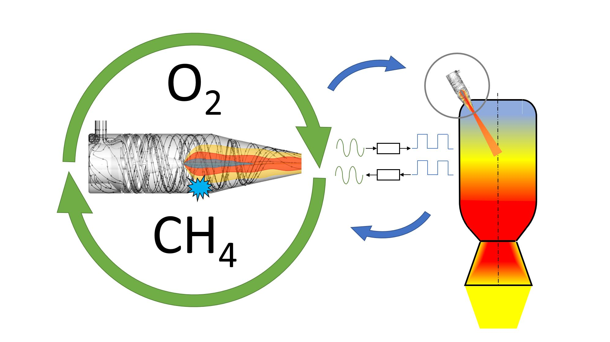
The control system acts changing the O/F ratio by increasing or decreasing the swirled mass flow rate of oxygen; a lean mixture corresponds to an increased cooling effect on the wall as result of the combined effect of an increased layer of oxygen protecting the walls and a reduced quantity of energy delivered inside the combustion chamber. The oxidizer–fuel combination selected is O2/CH4, because it is a green, well known and highly reacting mixture, able to deliver energy at various equivalence ratios with a relatively high density. Moreover this mixture is storable in space and nontoxic, reducing costs, and complexity of storage when compared to some other, more widely used, fuel–oxidizer combinations. Finally, when operating under lean conditions, combustion products are still rich in oxygen, thus favoring the ignition of the propellants in the main combustion chamber.
The aim of this work is to present the main characteristics required and the design solutions adopted for the igniter and to discuss the tests executed to evaluate quality and performance of the control system.
2. Igniter and Ignition System
Different types of igniters for rocket motors are available in the literature: these include hypergolic reactants, resistive elements (low voltage), augmented high voltage spark (liquid bi-propellant torch), pyrotechnics, catalyzed monopropellants, gas-dynamics systems, and high power plasma arcs [
4,
5]. During the development of our hybrid propulsion system, we have constantly used a pyrotechnic ignition system, the main disadvantage of which is the impossibility of re-ignite the engine. Moreover, on a laboratory-scale it’s preferable to have a controllable, reliable ignition system with a simple power regulation, which could be used in different aerospace applications, such as hybrid rocket motor or ramjet motor. Thus, a gas torch ignition system could be a good option for the motor initiation because of its relative simplicity and reliability [
6,
7].
The experimental basis of the current work is a general flammability study [
8] of various mixtures including the methane-oxygen with additives and impurities influencing the flame formation and ignition limits of gases. According to [
8] a methane-oxygen pure mixture is flammable on a wide range of concentrations; however, a stable ignition could exist only when a methane concentration lies between 5% and 60% by volume. Another important parameter involved in the ignition process is the spark energy required for reliable flame initiation. From [
8] it is known that the “ignitibility limit” for GOX/GCH
4 mixture is close to 1 mJ.
The study of recent publications in the area of interest for this work has allowed to qualify and quantify the combustion properties of methane-oxygen flames. Analytical estimation of the flame structure in this paper is based on the work of Melvin and Moss [
9] where the properties of methane-oxygen diffusion flames are given in a precise mathematical and physical model allowing a critical comparison between different reaction schemes and the elaboration of an analytical prediction of the mixture composition during the combustion process. Previously Bae et al. [
10] have found the stability limits of the oxygen–methane diffusion flame using the jet and vortex injectors combination. A model of a compact size injector was elaborated showing a dependence of the visible flame length on Reynolds number and O/F ratio.
The work of Ellis [
11] describes a background of a LOX/CH
4 swirled torch ignition system for a rocket engine and shows the flammability maps for various combinations of propellants. Pauly et al. [
12] show conditions of the flame attachment to the injector when applied to coaxial jets, flame stabilization in time and its liftoff distance during the flame stabilization.
The ignition characteristics of a small thrust rocket engine working on methane-oxygen mixture were described by Jiaqi et al. [
13]; the injectors’ configuration was determined in order to achieve a stable motor ignition. It was confirmed that a spark-plug directly connected to the rocket engine’s combustion chamber is not capable to supply enough energy for ignition. In this context, the design of a compact stand-alone torch igniter becomes an important key technology for reliable ignition of a rocket motor.
According to Li [
14], swirling flows of pure methane-oxygen diffusion flame similar to that of our work are characterized by a stable tubular flame for Φ ∈ (0.52, 1.05); outside of these limits, depending on the geometry of the combustion chamber and the injector, the flame could oscillate or be unstable.
The development of the torch ignition system for the Vinci upper stage engine was described by Frenken and Vermeulen [
15]. The components of the system were described and the main parameters of the system operation were discussed. It was shown that a compact gas torch igniter of 440 kW of thermal power could show a reliable operation when its design and flow conditions are optimized.
Kinetic mechanisms for modern CFD tools of methane-oxygen mixture combustion were studied by Haidn et al. [
16] in order to estimate a design approach for effective injectors geometry and flow conditions for startup combustion sequence and key requirements for the feasible ignition system.
Moon et al. [
17] carried out an experimental study on a methodology to estimate the reliability of a pyrotechnic ignition system for a hybrid rocket motor, which could be extended to the gas torch ignition system discussed in this work.
Vortex combustion chambers are thus known in the literature for their capability to improve fuel mixing and combustion. For example, Yi et al. [
18] shows an igniter, based on a pre-mixed flame, in which it is possible to obtain an excellent level of mixing in the combustion chamber by using crossed flow injection. In this work another concept has been developed: the swirled flow, in fact, surrounds the methane jet so as to keep the flame away from the walls of the chamber up to its outlet section. This allows small size and weight of the igniter with undoubted advantages. Furthermore, on [
18] the effects of a flame not parallel to the axis on the grain combustion is not described. In our tests we found that a pilot flame parallel to the engine axis guarantees uniform combustion in the radial direction. For these reasons the preliminary design of our igniter was challenging: before manufacturing the prototype, many configurations were designed and tested, with the help of numerical fluid dynamics, varying combustion chamber length, fuel injector and nozzle geometries.
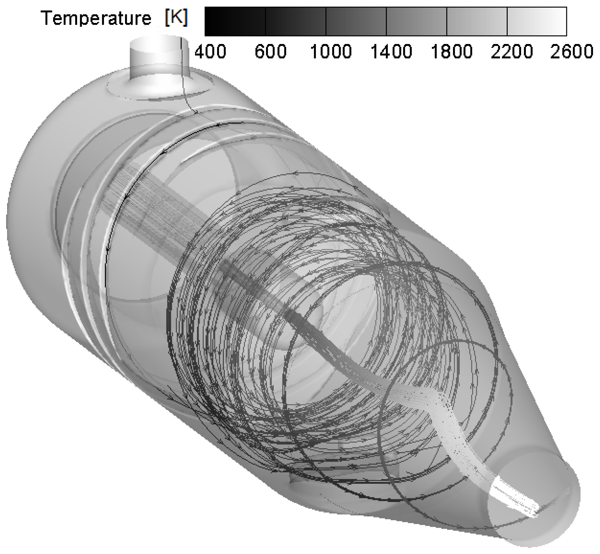
Figure 1 shows the baseline geometry selected with the expected flow lines distribution colored by temperature.
During this phase, many solutions for the CH
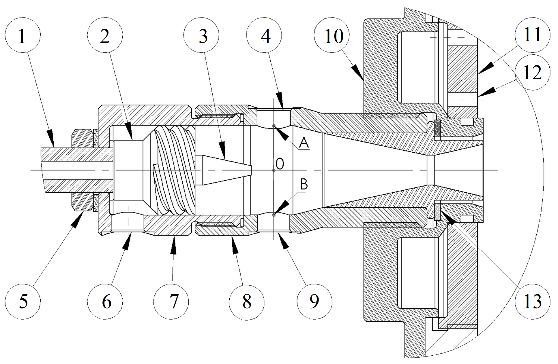
4 injector geometry were tested; as a result, the conical injector configuration was selected and manufactured because of its ability to reduce the surfaces exposed to the aggressive attack of radicals combined with intense heat fluxes. The igniter assembly with the rocket motor shown on
Figure 2 consists of the following components: 1—fuel inlet, 2—oxidizer injector, 3—fuel injector, 4—sensor interface, 5—fuel inlet fastener, 6—oxidizer inlet, 7—igniter casing, 8—combustion chamber, 9—spark plug interface, 10—oxidizer closure, 11—injector plate, 12—injector interface, 13—igniter sealing.
As shown in the schematic above, while methane is injected by means of a jet parallel to the axis (1), oxygen enters the combustion chamber (6) passing through helical ducts (2) which impart the desired circumferential motion. The swirled flow thus, surrounding the fuel jet, controls the extension of the reacting region and its temperature; by increasing or decreasing the oxygen mass flow rate it is thus possible to protect the walls until the exit section. Downstream of the CH4 injector are located the spark plug (9) and thermocouple (4) interfaces; flow temperatures have been measured varying the position of the thermocouple along the 24 mm long diameter AB.
To ensure a high resistance to thermal fluxes and corrosion all the components shown in
Figure 2 are made of stainless steel 310.
Table 1 completes the description of the igniter summarizing the required performance in case of use as hybrid rocket igniter and also as solid or liquid fueled ramjet pre-heater (simulating the same conditions expected, for different Mach numbers, downstream of their inlet).
As the table shows, attention has been paid especially to the reliability of the ignition requiring a very high success rate within three consecutive ignitions. Indeed the control system is able to manage up to 16 ignition attempts, each 3 s long, thus ensuring a high probability of ignition.
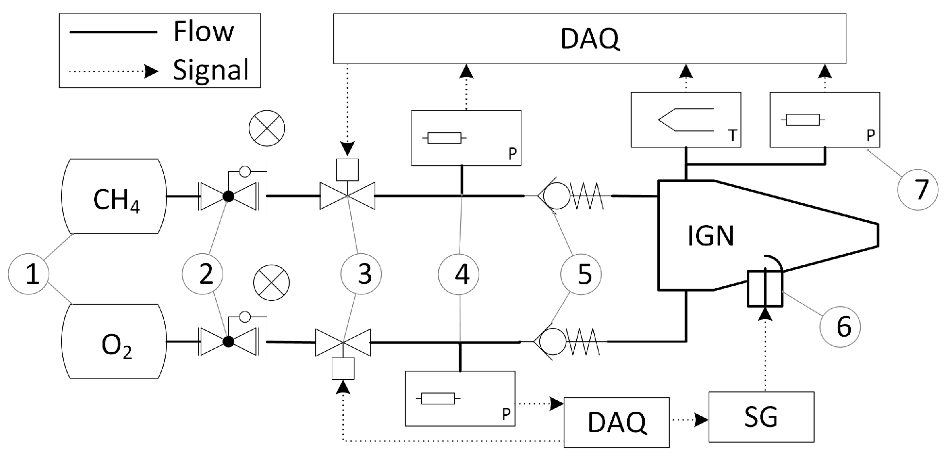
The ignition system, shown in
Figure 3, is composed by a feeding system and a control system.
The feeding system is composed by two high-pressure tanks filled by oxygen and methane. Each flow, passing through a pressure regulator valve (2), reduces its pressure; then, downstream of a flow valve (3) controlled by the ignition algorithm, a non-return spring loaded check valve (5) is preventing backflow phenomena. Finally both flows are injected into the combustion chamber through the injectors and ignited by a spark plug (6) through the spark generator (SG).
The pressure sensors (4) along the feeding lines and inside the combustion chamber are used to determine the mass flow rate of the propellants; moreover a thermocouple installed inside the combustion chamber reads the temperature. These data, sent to the 14 bit A/D converter of DAQ are processed by using a control algorithm developed in the CPL and written using the G-Language of the LabVIEW environment.
The pressure transducers have been installed using T-adapters of the same diameter of pipes to avoid losses allowing thus a more precise measure of the static pressure in the system. They can be positioned, if required, upstream of the flow valves (3) to estimate the pressure drop and flow coefficients inside the valve. Finally, the thermocouple installed inside the combustion chamber is connected to an adjustable adapter, allowing measurements along the chamber diameter; the adapter connection is also compatible with the pressure transducer (7).
3. Qualification Tests
More than 400 tests were performed, verifying mainly resistance and reliability of the components. Particular attention has been paid to measuring temperature and pressure in the feed lines and inside the combustion chamber. These data have been used as feedback informations to capture the ignition moment and to control the mass flow rate and energy output of the igniter. Performance in terms of ignition limits, repeatability and delay have been verified; finally, flame stability at low and high-pressure and power released have been investigated. All these tests have been performed using the system to ignite a hybrid rocket.
A series of measurements has been performed, for pressure and temperature, varying the mass flow rates and thus the O/F ratio of the mixture; every measure was repeated at least 25 times for all points of interest in order to collect statistical data assessing the repeatability of the ignition process.
The mass flow rate of oxidizer and fuel has been calculated carefully by using the water displacement method, a procedure allowing the calculation with a very low margin of error. To perform this measurement, the ignition system was assembled downstream of a large volume water tank. Thus the valves have been opened for a period of time sufficient to ignore inertia effects; the amount of water displaced during this time was measured and the gas compressibility correction was recalculated.
Test have also been performed to evaluate the “energy absorbed”, that is the quantity of the heat efficiently transferred to the solid grain of paraffin. This is a fundamental parameter for solid fueled hybrid rocket and ramjet because it is connected with the energy required to liquefy and or vaporize the fuel allowing homogeneous reactions in the main combustion chamber. The ignition system has been assembled with our hybrid engine; thus, many tests were executed, all with constant motor configuration and same initial grain mass and geometry. Varying the mass flow rate of CH
4 and O
2 and thus their O/F ratio, the grain consumption due to the paraffin melting and evaporation processes were measured; finally, the power absorbed by the fuel grain has been evaluated by calculating the variation of its mass:
where
is the mass of melted paraffin,
and
are the averaged specific heat capacity of the paraffin in solid and liquid state, respectively,
is a difference between paraffin fusion point and ambient temperature,
is a difference between liquid paraffin temperature at the end of the experiment and the fusion temperature,
is a specific heat of paraffin fusion,
is the duration of the experiment. The quantity of evaporated paraffin was considered negligibly small and was not considered in the Equation (
1).
Table 2 finally shows the maximum error allowed in the measurement of the quantities of interest, evaluated considering all the possible sources of error in the system.
All the experimental tests have been repeated at least 2 times to minimize the possibility of errors during the execution.
4. Results and Discussions
Opening the valves in angles ranging from 0° (fully closed position) to 90° (fully open position), the pressure difference registered between the sensors (4) and (7) increased from 1 to 5 bar inside the fuel line and 1.5 to 5 bar inside the oxidizer line. Measurement of the pressure difference between sensors (4) and (7) takes into account the check valves and other local pressure losses.
Figure 4 shows the results of all the experiments for both propellants, where the measured mass flow rate has been normalized by using a reference values of 4 g/s for the oxidizer and 0.7 g/s for the fuel.
Here we can observe a strong correlation between the inlet total pressure and mass flow rate, as well as the influence of the valves opening angles. With these data it is possible to easily calculate the O/F ratio (and total mass flow rate) by using the following correlation:
The minimal amount of gas required for 16 ignitions of the hybrid rocket motor [
1] are
= 105 g, and
20.56 g, calculated taking into account the average ignition delay of 1.16 ± 0.48 s measured experimentally.
Pressure levels after the check valves and in the combustion chamber have been measured during the ignition process and are shown on
Table 3, as an average of 50 tests. Here, two opening levels have been used: partially open, used for the flame initiation process, and fully open required during the fully developed combustion process. The pressure regulator valves (2), has been set to a pressure
bar for both the fuel and oxidizer lines. After a group of 50 tests mean pressure values and standard deviation have been estimated in order to provide the flame temperature and energy output variation in a group of tests.
These values of the standard deviation show the required repeatability of the flow properties. A sequence of 100 attempts was performed to test the ignition probability, each attempt with duration of 1 s. Not a single failure of the ignition system was found during this test and the ignition probability has been shown to be 99% for the single attempt, and 99.99% for three attempts in a sequence. These values can be considered strictly speaking valid just for the flame initiation process because other possible failure probabilities such as malfunction of sub-components like spark plug, valves, sensors, control system or others have not been included. However, after more than 400 tests not a single sub-system component failure has found, suggesting a very high level of reliability for the whole system.
Figure 5 shows the results obtained during the tests done to evaluate the power absorbed by the grain; data are reported as total propellant mass flow rate vs. O/F ratio with the absorbed power as parameter. A strong relation between the mass flow rate and the absorbed energy has been observed; among all the possible combinations, the couple
= 2.38 g/s and O/F = 5.78 has been considered optimal because it provides sufficient power for the rocket or ramjet motor ignition (no ignition failure was detected among hundreds of tests) and allows an efficient cooling process.
There were 14 experimental points in the O/F ratio and mass-flow-rate domain used to draw the contours of
Figure 5.
The left-upper corner of the
Figure 5 corresponds to high energy output at near stoichiometric values; the low O/F ratio of this region makes it useless because decreasing the mass flow rate of the swirling flow we are decreasing the efficiency of the cooling layer protecting the wall against overeating.
Figure 6 shows the temperature values measured along the vertical line AB, defined earlier (
Figure 2). The flow conditions are the same giving the optimal solution identified with the previous tests.
First of all, the effect of the thermocouple on the flow was tested: it partially brakes the cooling vortex and increases the wall heating. This effect is dependent on the thermocouple position. After various tests, the optimal thermocouple position was found to be at y = −3.0 mm from the axis, being y the vertical coordinate along the AB segment with zero coincident with the injector axis. This position allows a detection of the temperature rise during the ignition process reducing the interference with the cooling vortex. To confirm the efficient effect of the swirling flow in cooling the wall, the maximum temperature registered during 20 s of combustion has been T = 95 ± 2 °C which is significantly lower than 1150 °C allowed for the alloy AISI 310S in continuous service [
19]. The efficiency of the cooling effect has been also qualitatively observed during a long test sequence of 180 s. The thermocouple was removed from the combustion chamber in order to reduce the disturbances in a swirling flow. Ignition was detected by the change of the exhaust temperature. No significant heat loads, capable of damaging the walls of the combustion chamber or its components, including the nitrile o-rings, have been experienced; the igniter has been disassembled without using heat protection.
It is important to highlight that the total measurement error reported in
Figure 6 includes the error due to the thermocouple positioning, estimated to be of order of
mm.


