Article

Design and Test of a Student Hybrid Rocket Engine with an External Carbon Fiber Composite Structure

Institute of Space Systems (IRAS), Technische Universität Braunschweig (TUBS), 38108 Braunschweig, Germany
*
Author to whom correspondence should be addressed.
These authors contributed equally to this work.
Aerospace 2020, 7(5), 57; https://doi.org/10.3390/aerospace7050057
Submission received: 13 February 2020 / Revised: 10 April 2020 / Accepted: 9 May 2020 / Published: 13 May 2020

Abstract

:
The development of hybrid rockets offers excellent opportunities for the practical education of students at universities due to the high safety and relatively low complexity of the rocket propulsion system. During the German educational program Studentische Experimental-Raketen (STERN), students of the Technische Universität Braunschweig obtain the possibility to design and launch a sounding rocket with a hybrid engine. The design of the engine HYDRA 4X (HYbridDemonstrations-RaketenAntrieb) is presented, and the results of the first engine tests are discussed. The results for measured regression rates are compared to the results from the literature. Furthermore, the impact of the lightweight casing material carbon fiber-reinforced plastic (CFRP) on the hybrid engine mass and flight apogee altitude is examined for rockets with different total impulse classes (10 to 50 kNs). It is shown that the benefit of a lightweight casing material on engine mass decreases with an increasing total impulse. However, a higher gain on apogee altitude, especially for bigger rockets with a comparable high total impulse, is shown.

1. Introduction

Hybrid rocket propulsion systems offer several advantages compared to solid or liquid propulsion, such as operational safety, thrust throttling ability, and lower cost due to a simple system design, as stated in [1,2]. However, several drawbacks prevented the achievement of an advanced technical readiness level (TRL) in the past [3], which hindered the establishment of hybrid propulsion systems in the commercial space market [4]. One disadvantage of hybrid propulsion is a low fuel consumption rate, called the regression rate, which can lead to a low thrust density and sometimes complex fuel grain shapes [5]. Another challenging aspect is the inconstant oxidizer-to-fuel mass ratio during operation. It is caused by the fuel grain surface, which changes with continuing fuel consumption [6]. These disadvantages offer a wide range of research potential; hence, various aspects of hybrid rocket engines (HRE) are addressed in the respective research. One of the main parameters under research is the experimental characterization of the fuel regression rate as investigated in [2,7,8] and how it is linked to heat transfer in the combustion chamber [9]. The regression rate also depends on other parameters like propellant choice [10,11] and the oxidizer injecting system [12,13]. Other aspects like throttling, combustion modeling, or design optimization were investigated in [14,15,16], respectively. Due to the advantages of HRE, they are suitable for a variety of space applications such as space launch systems [1], upper stages [17], lunar and Mars ascent stages [5,18], and sounding rockets especially for university education. Hence, there are numerous activities of hybrid rocket engine development at universities around the globe. For example, Tsohas et al. [19] described the 4 kN hybrid rocket development and launch at Perdue University, where the engine was propelled with hydrogen peroxide (H 2 O 2 ) and low density polyethylene (LDPE). At Tokai University, Japan, students developed engines with a thrust of up to 600 N that was achieved by using a propellant combination of nitrous oxide (N 2 O) and wax-based fuel [20]. Meanwhile, the Stratos hybrid rockets that were developed by team DARE (Delft Aerospace Rocket Engineering) of Technical University Delft used a fuel combination of sorbitol, paraffin, and aluminum powder. The engine DHX-200 Aurora of rocket Stratos II+ reached a thrust of 10 kN and a total impulse of 100 kNs [21]. In Germany, the hybrid rocket activities of student groups have been expedited by a national educational program called Studentische Experimental-Raketen (STERN) that was initiated by the German Aerospace Center (DLR) Space Administration in 2012 and is funded by the Federal Ministry of Economic Affairs and Energy (BMWi) [22]. This program allows students from German universities to develop and launch a supersonic sounding rocket [22]. The students are familiarized with the processes and reviews of a real aerospace project. The primary objectives of the rockets comprise a minimum altitude of 3 km , a minimum velocity of Mach 1 , and equipment with an onboard data transmission and a recovery system for a safe landing. During the project, the student teams were continuously supervised by experts in the field (Rocket propulsion (DLR Trauen, DLR Lampoldshausen) and DLR Mobile Raketenbasis (MORABA)) and the DLR Space Administration [23]. The participating student teams were able to launch their individual rockets from Esrange (European Space and Sounding Rocket Range) Space Center, Sweden [24]. Several of them used a hybrid propulsion system for their rockets, like the team of Hochschule Bremen. The rocket AQUASONIC used a N 2 O/polyethylene (PE) engine to reach an altitude of about 6.5 km [24]. The HyEnD (Hybrid Engine Development) team of Universität Stuttgart developed the rocket HEROS that also used N 2 O as the oxidizer, but in combination with paraffin as the fuel. This engine showed a design thrust of 10 kN and a total impulse of over 100 kNs [24]. Furthermore, the team of Universität Bremen contributed to the STERN program. They developed the rocket ZEpHyR (ZARM Experimental Hybrid Rocket), which applied an engine with liquid oxygen (LOX) and paraffin as propellants and achieved a total impulse of 54 kNs .
Another contribution to the program was made by the student association called ExperimentalRaumfahrt-InteressenGemeinschaft e.V. (ERIG), on behalf of Technische Universität Braunschweig. The students were able to develop and launch successfully the sounding rocket Faust in 2015, which used a hybrid rocket engine [23]. Due to the success and the excellent opportunity for the practical education of university students, the STERN program was continued in a second phase since 2017 as STERN II. The rocket Faust II shall be developed as a successor of Faust, where the hybrid rocket engine shall be improved regarding performance and lightweight design. The design, main characteristics, and performance of the Faust engine HYDRA 3X is described in the following. Based on this, the design changes for the advanced engine HYDRA 4X, which will propel the Faust II rocket, are examined in detail, before the first engine test results are presented. Measured regression rates are compared to the results from the literature. Furthermore, a detailed analysis of the impact of two different engine casing materials is discussed. Finally, the conclusion and outlook on the effects of the new engine construction on lightweight design and rocket performance are presented.

2. Materials and Methods

2.1. Overview of the Sounding Rocket Educational Project within the STERN Program

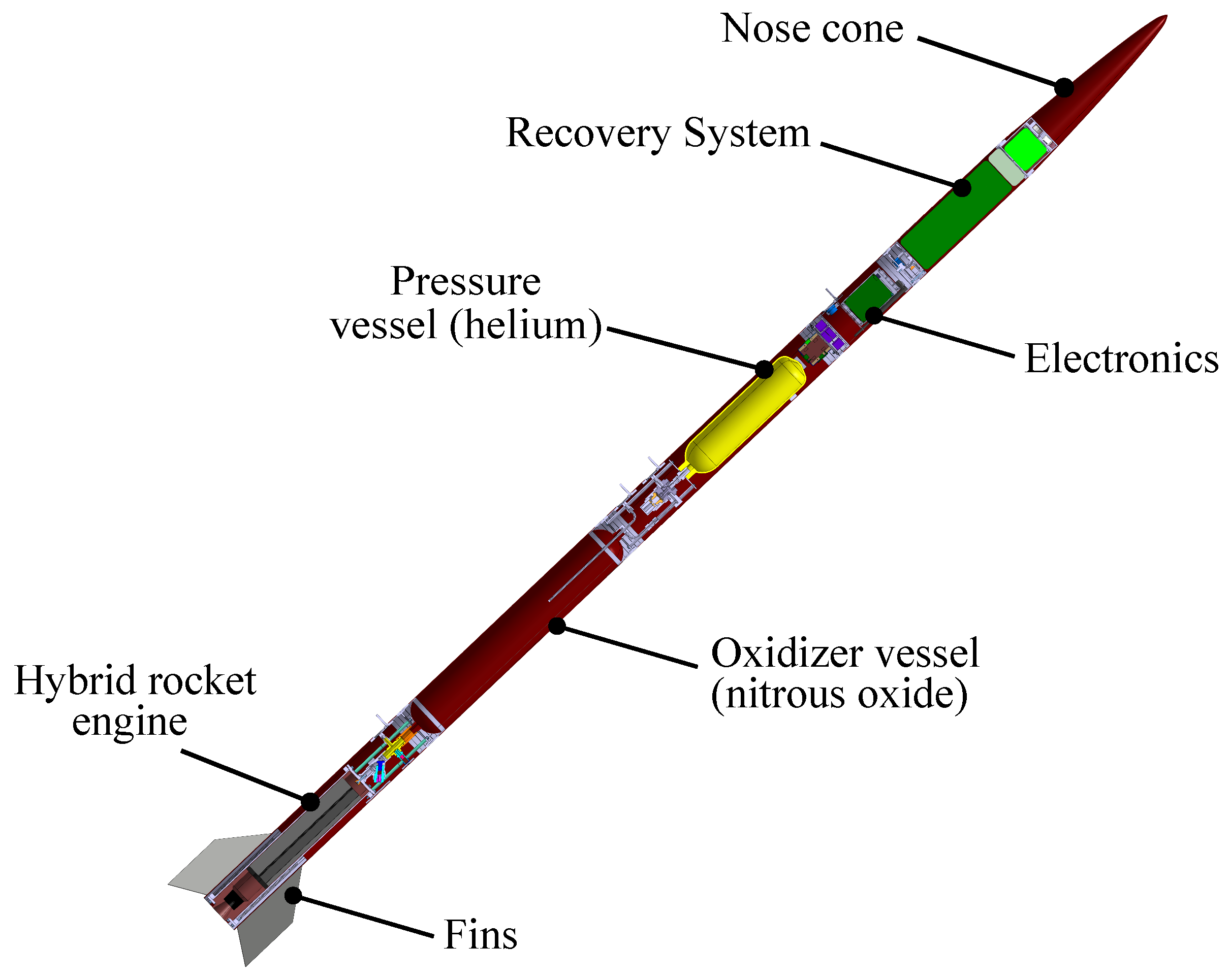
The main objective of the STERN program is the provision of experience for students in overall system design. A complete rocket system is to be designed with different subsystems to achieve the project requirements. This includes ground segment design, system operation design, project planning, and documentation. An overview of the whole project content is presented in Figure 1. Various subsystems of the rocket are addressed within the flight segment. This is also shown in Figure 2, where the rocket subsystems are visualized. One main subsystem is the propulsion system, where the engine and valve and feeding systems are designed. The engine design and verification are emphasized in this article.

2.2. Design of the Faust Rocket and HYDRA 3X Engine

Faust is a sounding rocket, which is propelled by a hybrid rocket engine. A schematic of the rocket is shown in Figure 2, and its main characteristics are listed in Table 1. Faust has a modular design of eight segments. The nose cone is part of the two-stage recovery system that is located on top of the electronics section. The complete propulsion system consists of a pressure vessel for pressurization of the oxidizer vessel, valves, feeding lines, and the hybrid engine. Fins for flight stability are connected to the body tube that accommodates the engine [25]. A successful launch with a maximum altitude of 5400 m was performed in 2015.
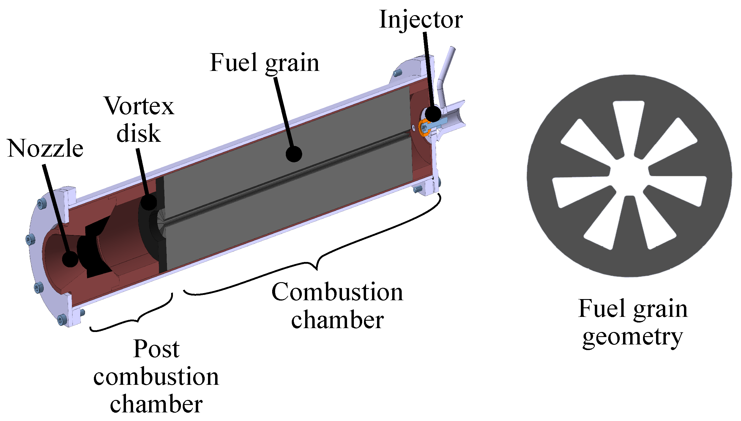
A hybrid engine was chosen for the Faust rocket because of the advantages of the propulsion concept. The operational safety is suitable for a student project, and the propellants are storable and relatively safe to use. The hybrid engine HYDRA 3X uses a propellant combination of liquid N 2 O as the oxidizer and a solid mixture of 70 % hydroxyl-terminated polybutadiene (HTPB) and 30 % aluminum powder as the fuel [26]. The aluminum was added to increase the fuel regression rate. Engine test runs with HYDRA 3X showed an increase in the regression rate of about 20 % compared to tests without the addition of aluminum powder [26]. The engine design shows typical components of a hybrid engine, such as an injector for feeding and vaporizing oxidizer into the following combustion chamber [27]. It is based on a shower-head injector that additionally uses a cone for diverting the oxidizer to ensure a better distribution of the mass flow. The propellant fuel is cast directly into the combustion chamber, which uses a star-shaped mold for creating the required fuel geometry, which is presented in Figure 3. The fuel grain ends at the vortex disk, which generates a large vortex flow. This provides the required mixture of both propellants. Subsequently, a conical convergent-divergent nozzle is located at the end of the engine [26,28,29].
Most parts of the engine structure are manufactured from phenolic paper due to advantageous ablative cooling characteristics. The nozzle throat is additionally reinforced with graphite to withstand high thermal loads during combustion. The engine is encapsulated by a steel casing for resistance of combustion pressure loads. The engine outer diameter is 0.09 m and therefore smaller than the rocket diameter. Hence, an additional structure tube is necessary that is added to the engine casing mass. Structural and performance data of HYDRA 3X are given in Table 2. A successful flight of the Faust rocket was performed with the HYDRA 3X engine. It burned for 10 s with a mean thrust of 1.25 kN . After a 37 s flight time, an apogee altitude of 5.4 km was reached [23]. The following objectives for the Faust II engine, HYDRA 4X, within the STERN II project, were chosen:
  • Apogee altitude of 10 km;
  • Increased engine thrust and total impulse;
  • Improved engine power-to-mass ratio;
  • Integrated lightweight casing made from CFRP.

2.3. Design of Hybrid Rocket Engine HYDRA 4X

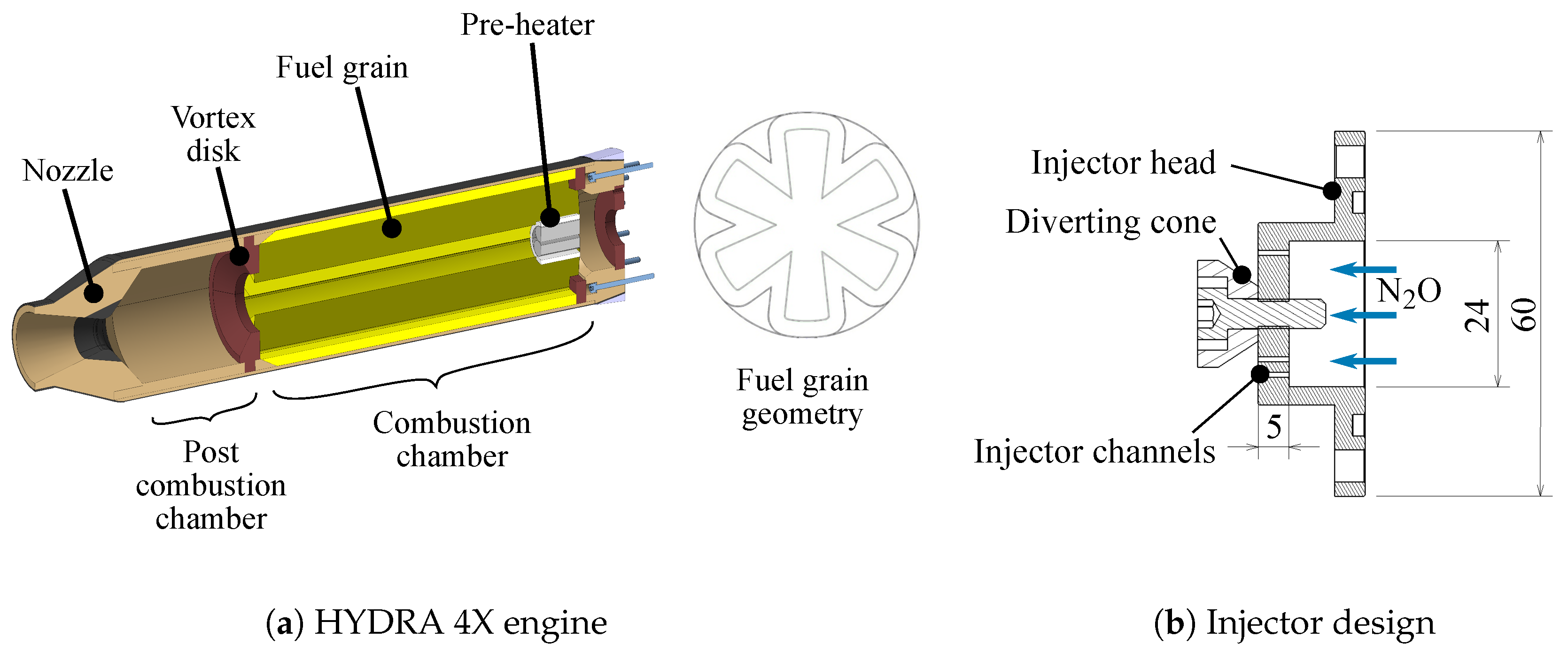
After the successful application of the HYDRA 3X engine, the HYDRA 4X engine for the Faust II propulsion system was planned. It uses pure HTPB as fuel, waiving additional aluminum powder. This propellant is cast into the engine at a liquid state. It cures by using hardener and therefore becomes solid. The grain geometry is created by using a casting mold that is removed after the curing process. The structure parts are made from phenolic paper, while the nozzle throat is additionally supported with graphite. The structure must be able to withstand the combustion pressure loads. Thus, the engine is equipped with a CFRP laminate coating that resists the operational pressure. The injector head is based on the design of HYDRA 3X. It is a shower-head injector with channel orifices of 0.8 mm . A diverting cone is added, as shown in Figure 4b. The oxidizer flow impinges on this cone, which diverts the flow and directs it to the fuel grain. The current design of HYDRA 4X is presented in Figure 4a and key data in Table 2, respectively.

2.4. Performance Calculations

The technical design of the HYDRA 4X is built upon a first evaluation of an ideal ratio of N 2 O and HTPB for a maximum specific impulse. NASAs CEA-Code (Chemical Equilibrium with Applications) suggests an oxidizer-to-fuel mass ratio of O / F = 7 , using input data from Table 3, with a frozen composition assumed after the nozzle throat. The O/F is used to calculate combustion characteristics for the combustion chamber pressure and nozzle exit pressure. Since the ambient pressure of the rocket changes with altitude, a value for nozzle exit pressure needs to be defined. In this case, the nozzle is adapted to ambient pressure at half of the maximum flight altitude. Input data and relevant results of CEA are shown in Table 3.
Based on former flight tests’ experience, a lift-off acceleration of around 5 g should be achieved to ensure a reliable launch. This is the boundary condition to determine the required thrust F and, thus, mass flow m ˙ . This results in a thrust of 2.25 kN for the overall rocket mass of 46 kg . From:
m ˙ = F η e n g i n e · I s p , C E A
Ref. [1], and:
m ˙ f = m ˙ O / F + 1
the required fuel mass flow m ˙ f can be calculated. A global engine efficiency of η e n g i n e = 91 % was determined via engine tests during the first STERN program. This is a preliminary design assumption. Different star-shaped fuel grain geometries were iterated regarding the number of star spikes and shape. A constant regression, perpendicular to the fuel grain geometry over full burn time, was assumed. The regression rate for the preliminary design was approximated to r ˙ = 0.6 mm / s from previous in-house measurements. It was adapted with every hot fire test of HYDRA 4X for the design iteration. The mean regression rate of a hot fire test was obtained through weighing the engine before and after the test. The weight difference was converted into a geometric regression, by dividing the weight difference with burn time and fuel grain surface area prior to testing. An optimization was carried out for burn time t b , thrust profile according to burn time, and initial mass flow levels, given by Equation (2). This led to a star-shaped fuel grain with the parameters shown in Section 4. Using fuel grain geometry and mass flow m ˙ f , the O/F-ratio determines the subsequent oxidizer mass flow m ˙ o x :
m ˙ o x = O / F · m ˙ f .
The propulsion system of Faust II was designed to inject liquid oxidizer into the engine. A pressure of 5 MPa was chosen for pressurization of the oxidizer vessel. This pressure level ensured a liquid state of the nitrous oxide and thus operational temperatures up to 293 K [30]. This temperature agreed with ambient temperature requirements set by a planned launch from ESRANGE Space Center. With combustion chamber pressure p c and oxidizer vessel pressure p o x , the theoretical injection speed v t h can be calculated using the oxidizer density ρ o x , assuming incompressible, stationary, and isentropic Bernoulli flow (cf. [1]):
v t h = 2 ρ o x ( p o x p c )
A diameter of 0.8 mm and a length of 5 mm were chosen for a single injector orifice. The volume flow Q ˙ in a single circular orifice is decreased compared to its theoretical optimum due to stream tube contraction and pressure losses within the orifices [6]. This relation can be expressed by:
Q ˙ Q ˙ t h = Q ˙ v t h π 4 d 2 = C D
where the effects can be combined into a single factor C D . This coefficient is measured in every test to iterate the number of injecting orifices. Equation (4) is only applicable to negligible changes of density along the injecting orifice length. Due to the strong temperature and pressure dependency, this is only partially applicable to nitrous oxide injection with a strong pressure gradient from the feeding line to the combustion chamber present. However, this approach was used in combination with the coefficient C D to approximate the real flow behavior of the nitrous oxide.
The total number of injecting orifices n o x can be calculated by:
n o x = m ˙ o x ρ o x · Q ˙
The strong temperature and pressure dependency of the N 2 O density ρ o x and its effect on the number of injector orifices is to be handled with special consideration. A good control of the N 2 O parameters during fueling can circumvent off-design engine operation. This is also achieved by varying the number of injector orifices according to N 2 O parameters.
An auxiliary function Γ is introduced in Equation (7) [7]. The mean of specific heat ratios γ calculated by CEA in Table 3 is used as input. The characteristic velocity C * and the throat area A t are calculated by Equation (8) using molar mass M, the temperature T c of the reaction product in the chamber (cf. Table 3), and universal gas constant R [7]. Subsequently, the nozzle throat diameter d t is computed in Equation (9).
Γ = γ · 2 γ + 1 γ + 1 2 · ( γ 1 )
C * = 1 Γ c R M · T c = p c · A t m ˙
d t = 4 π · A t
The momentum thrust coefficient C F 0 can be calculated according to Equation (10) by using the nozzle exit pressure p e [7]. Equations (7) and (10) are combined into the nozzle expansion ratio A e / A t in Equation (11) [7]. A conical nozzle is chosen due to simplicity in manufacturing. The divergence cone half angle was set to 15 . The length of the divergent nozzle l n o z z l e is calculated through Equation (12).
C F 0 = Γ · 2 · γ γ 1 · 1 p e p c γ 1 γ
A e A t = Γ 2 C F 0 · p e p c 1 γ = d e 2 d t 2
l n o z z l e = d e d t 2 · 1 tan ( 15 )
The thrust coefficient C F is computed by Equation (13), applying a correction factor to the momentum thrust coefficient C F 0 , correcting for the axial divergence of the exhaust of a conical nozzle [1]. The ambient pressure p a corresponds to the static pressure of the environment and is equal to p e at the design point. For following test data, the ambient pressure was measured at the test site. Note that this corresponds to an optimum C F achievable for conical nozzles.
C F = C F 0 · 1 + cos ( 15 ) 2 + A e A t · p e p a p c
The combustion η c and nozzle expansion efficiency η n o z z l e of the engine are calculated by Equations (14) and (15) as ratios of experimentally measured parameters to ideal design values. This approach enables a comparison of actual engine performance with design performance. As the parameters might shift in the hot fire test, all experimental values are taken as mean over full burn time. According to [1], the overall engine efficiency is then calculated by Equation (16). All design data of the HYDRA 4X engine in its latest iteration after the fourth hot fire test are summarized in Table 4.
η c = C e x p * C * = p c · A t C * · ( m ˙ o x + m ˙ f )
η n o z z l e = C F , e x p C F = F C F · p c · A t
η e n g i n e = I s p , e x p I s p = η n o z z l e · η c

3. Description of the Engine Test Bed

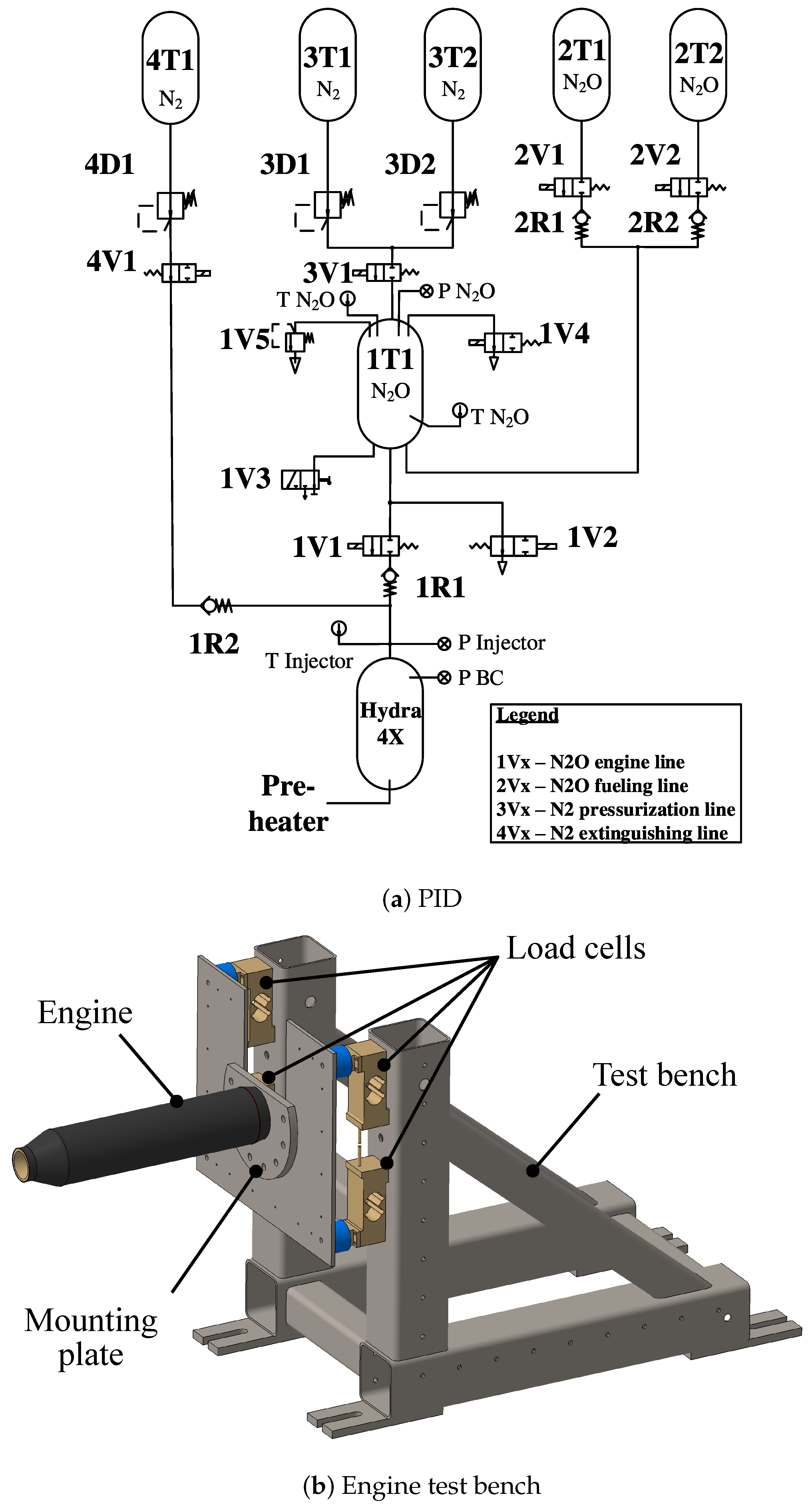
All engine tests are performed at the test facility of DLR Trauen, where all safety requirements can be achieved. The engine test bed for HYDRA 4X consists generally of two assemblies, the fluid supply system and the test bench. A schematic of the fluid supply system is presented in Figure 5a. The fluid supply system also includes the test bed electronics. An intermediate tank is used to store liquid N 2 O during the fueling process. Nitrous oxide is fed from cylinders directly into this tank where it can be pressurized to 6 MPa . In contrast to the rocket system, nitrogen is used for pressurizing the N 2 O tank on the test bed due to its better availability. Temperature and pressure within the intermediate tank are measured by three sensors. Strain gauges measure the tank weight during testing to control fueling and to determine oxidizer mass flow rates. After pressurization, the tank weight is set to zero. Thus, only the fueled nitrous oxide mass is measured. During the hot test, the intermediate tank is continuously pressurized by nitrogen. The change of tank weight during the hot test gives the oxidizer mass flow. The continuously added nitrogen mass flow for pressurization introduces a systematic error to the oxidizer mass flow measurement during the hot test. The additional weight of the nitrogen decreases the measured oxidizer mass flow. This systematic error is not corrected. Hence, all stated oxidizer mass flows are smaller than expected.
The oxidizer feeding line is mounted to the test bench and leads directly to the test injector. Liquid N 2 O is inserted into the engine through this component during the hot test. At this point, additional measurements are taken: temperature and pressure shortly in front of the injector are measured, as well as the combustion chamber pressure by a sensor connected to a small pipe that leads directly into the engine pre-chamber. Pressure is measured at a sampling rate of 1 kHz . The test bench is a robust steel construction that is modular and can be used for different engines, as is displayed in Figure 5b. The HYDRA 4X is mounted to the test bench using a mounting plate, which accommodates the injector and can easily be exchanged. Four load cells are integrated onto the test bench for thrust measurement. Data logging and valve controlling are realized by the National Instruments cRIO - 9074 controller [29]. It is located within an electronic box near the fluid supply system and can be controlled remotely from the test control center.

4. Results and Discussion

4.1. Hot Fire Tests and Iteration of Design

The results for the first four hot fire tests of HYDRA 4X engine are presented in the following. Design changes were made to increase engine performance between these tests. The changes of defined design parameters are summarized with the resulting measured values from corresponding hot fire tests in Table 5. The value G o x was computed according to [7]:
G o x = m ˙ o x A p
where A p is the free port area of the fuel grain. The mean port area over burn time was considered for the determination of the regression rate.
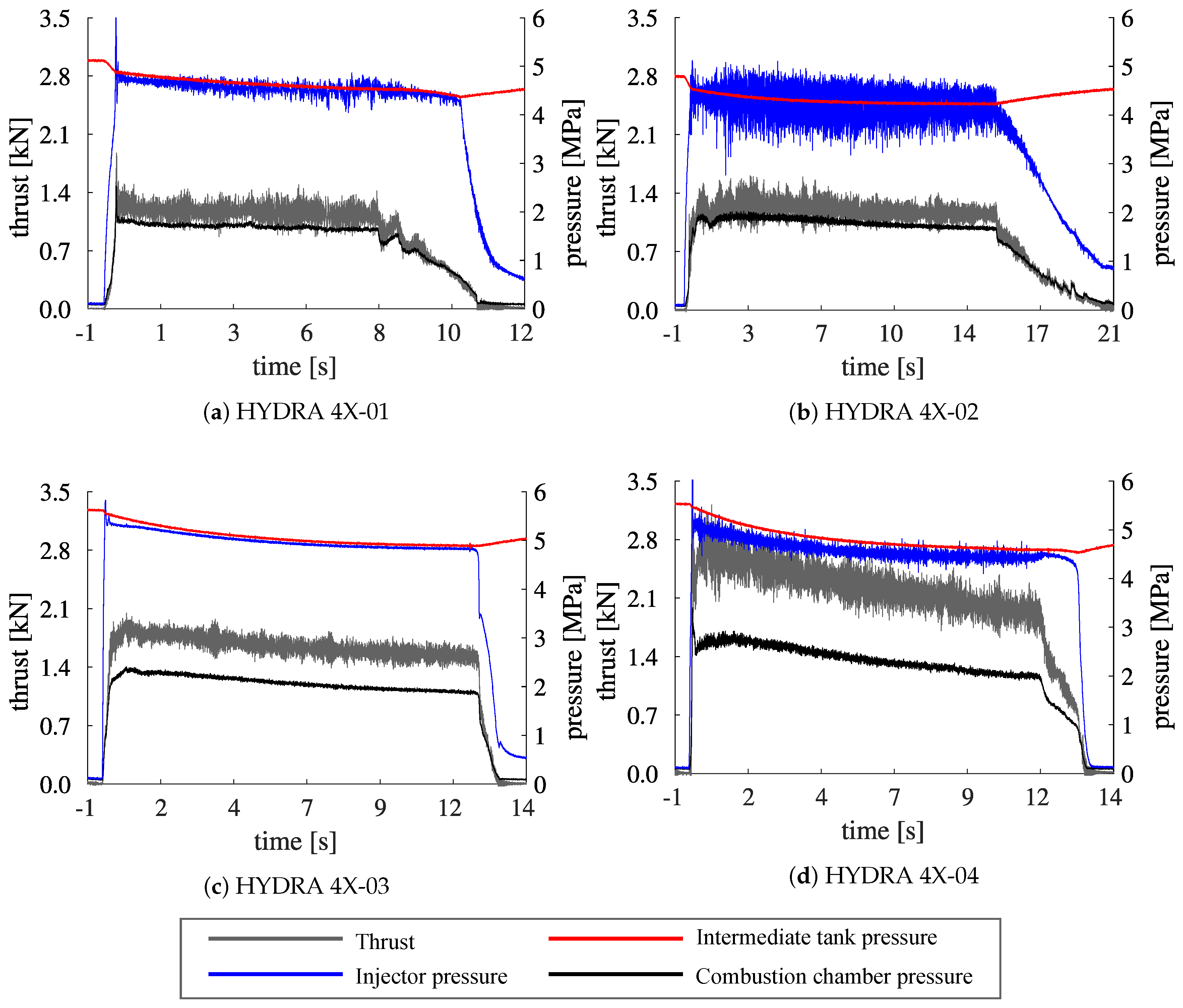
Pressure values of the intermediate tank, injector, and combustion chamber were measured during all engine tests. The measurements of the first four engine tests are presented in Figure 6. Three general test phases are visible in all four graphs: The first phase describes the condition when the intermediate N 2 O tank was filled and pressurized to a pressure between 4.8 and 5.6 MPa . The combustion phase started with opening of the main oxidizer valve, and the tank pressure reduced slightly as the oxidizer flowed into the engine. A decrease of tank pressure over time could be noticed. This was a result of an insufficient pressurization of the fluid supply system used, which was originally designed for lower oxidizer mass flows. Therefore, the achieved oxidizer mass flow decreased over burn time in every test, i.e., initial and end values were in the range of a 10% deviation of mean oxidizer mass flow over burn time. Tank and injector pressure differed by a small value that complied with pressure loss in the feeding line. Injector and chamber pressure showed increased values after opening of the main valve. After closure of the main valve, thrust and combustion chamber pressure decreased fast to values prior to ignition, while the intermediate tank pressure increased again. The injector pressure did not drop to ambient pressure again, because the feeding line was still pressurized. For the first two tests, the feeding line extended with about a 2 m length between the main valve and engine; cf. Figure 5a. Due to this, the engine received oxidizer for a longer time than desired after main valve closure. To reduce this effect, the main valve was relocated directly in front of the engine for the third and fourth test.
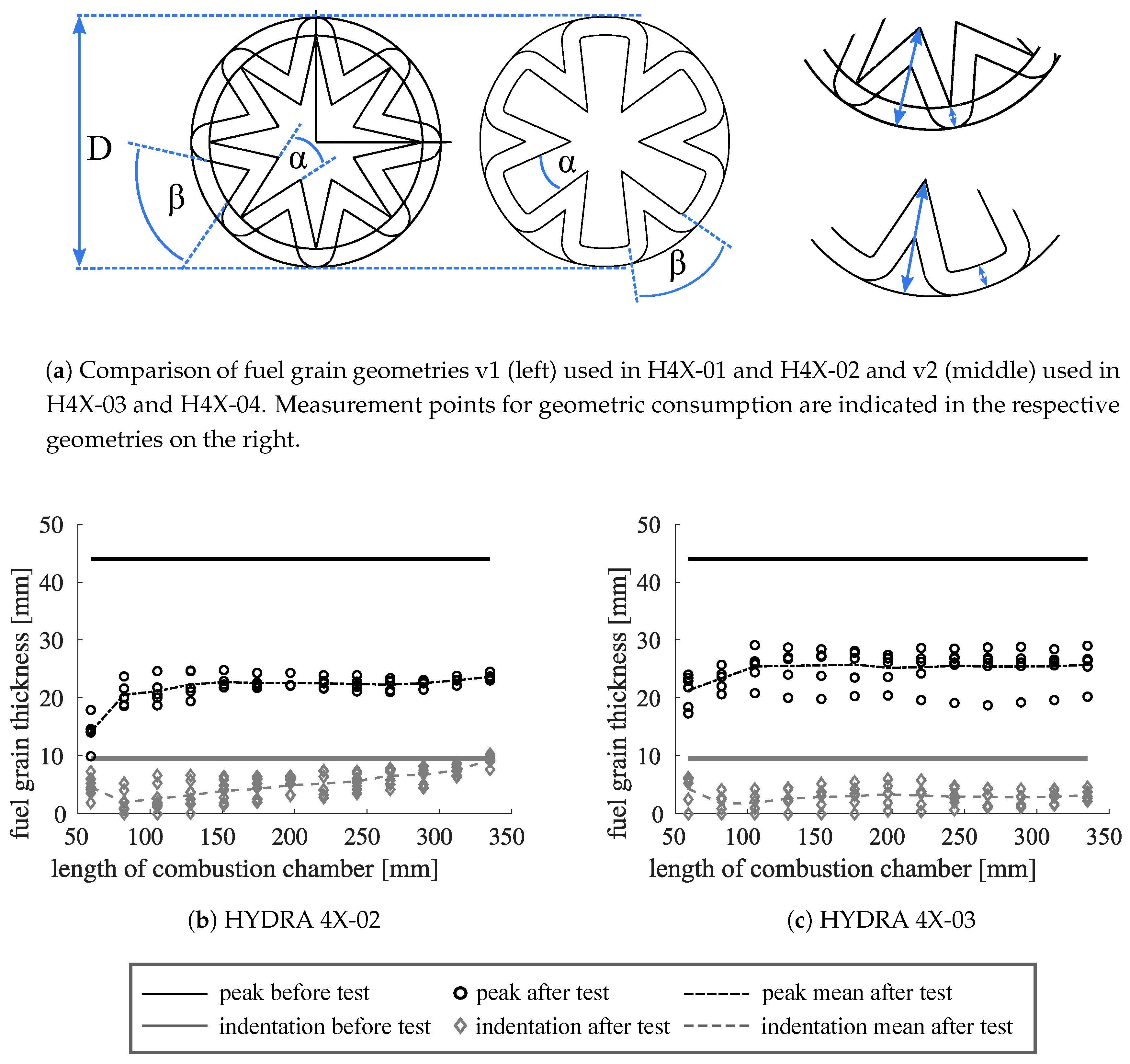
The mean thrust of the first two engine tests was about 1.2 kN , which was apparently lower than the design thrust. Accordingly, the average combustion chamber pressure of 1.8 MPa was low compared to the design value of 2.5 MPa . Analysis of test parameters yielded that the target value for oxidizer mass flow was not reached and the nozzle was manufactured inaccurately. Design changes between HYDRA 4X Versions 01 and 02 were made to increase engine performance: nozzle manufacturing was improved; post combustion chamber length was increased by 30%; and injector design was changed to improve mass flow through an increase of orifice number and manufacturing quality and the combustion of both propellants by flattening the diverting cone angle. Since there were no remarkable changes between the performance results of HYDRA 4X-01 and 4X-02, the consumption of the star-shaped solid propellant grain was examined for the second test in Figure 7b. Two main aspects could be determined. First of all, it was evident that HTPB consumption decreased with combustion chamber length. The mean consumption showed values between 30 mm at the fuel grain front and only 20 mm at the end considering the star peaks. This was also apparent for star indentations where consumption values varied from 7 mm to 0 mm . The latter meant no consumption at all. Hence, the consumption of star indentations was significantly lower than that of star peaks. The authors assumed that although the target mean regression rate was reached, the uneven consumption over length and major differences between star peaks and indentations contributed to engine performance, as the overall fuel grain surface in the combustion process was decreased.
As a result, the fuel grain geometry was changed for the test of HYDRA 4X-03 as presented in Figure 7a with parameter values summarized in Table 6. The number of star peaks was decreased from eight to six, and the geometry was changed so that consumption of star indentations was augmented. The consumption measurements of HYDRA 4X-03 showed that the design changes enhanced the HTPB consumption, especially for star indentations, as can be seen in Figure 7c. Additionally, a more even consumption along engine length was demonstrated. Therefore, a higher mean thrust value of about 1.6 kN at a chamber pressure of 2 MPa could be reached, as presented in Figure 6c. These values were still below the design parameters, which could be traced back to a low oxidizer mass flow. As a result, the injector was adapted once more between Tests 03 and 04 by increasing the number of injecting orifices.
With this adjustment, a mean thrust of approximately 2.3 kN was reached at a chamber pressure of 2.3 MPa , an injector pressure of 4.6 MPa , and an oxidizer mass flow of 1.01 kg / s , as presented in Figure 6d. However, the mean oxidizer mass flow exceeded the design value of 0.931 kg / s . This resulted in a mean O/F of 8.4 over the full test time, compared to a design O/F of seven. The fuel mass flow of 0.123 kg / s was in good accordance with the design value of 0.133 kg / s . To reach an appropriate oxidizer mass flow, the number of injecting orifices would be decreased, and the directional characteristic of the injector would be changed to supply oxidizer more directly at the star indentations. To achieve this directional behavior, the injector orifices would be aligned with the angular position of the star indentations. HYDRA 4X-04 yielded 86 % efficiency of the design I s p . This global efficiency could be divided into 87 % combustion efficiency and approximately 99 % nozzle efficiency. Although the minimum design thrust was surpassed, it could only be achieved through an excess of injected oxidizer mass flow. As the flight fluid supply system would not be able to sustain this increased oxidizer mass flow for the complete burn time, further work would have to be carried out to achieve design performance at tolerable oxidizer mass flows.
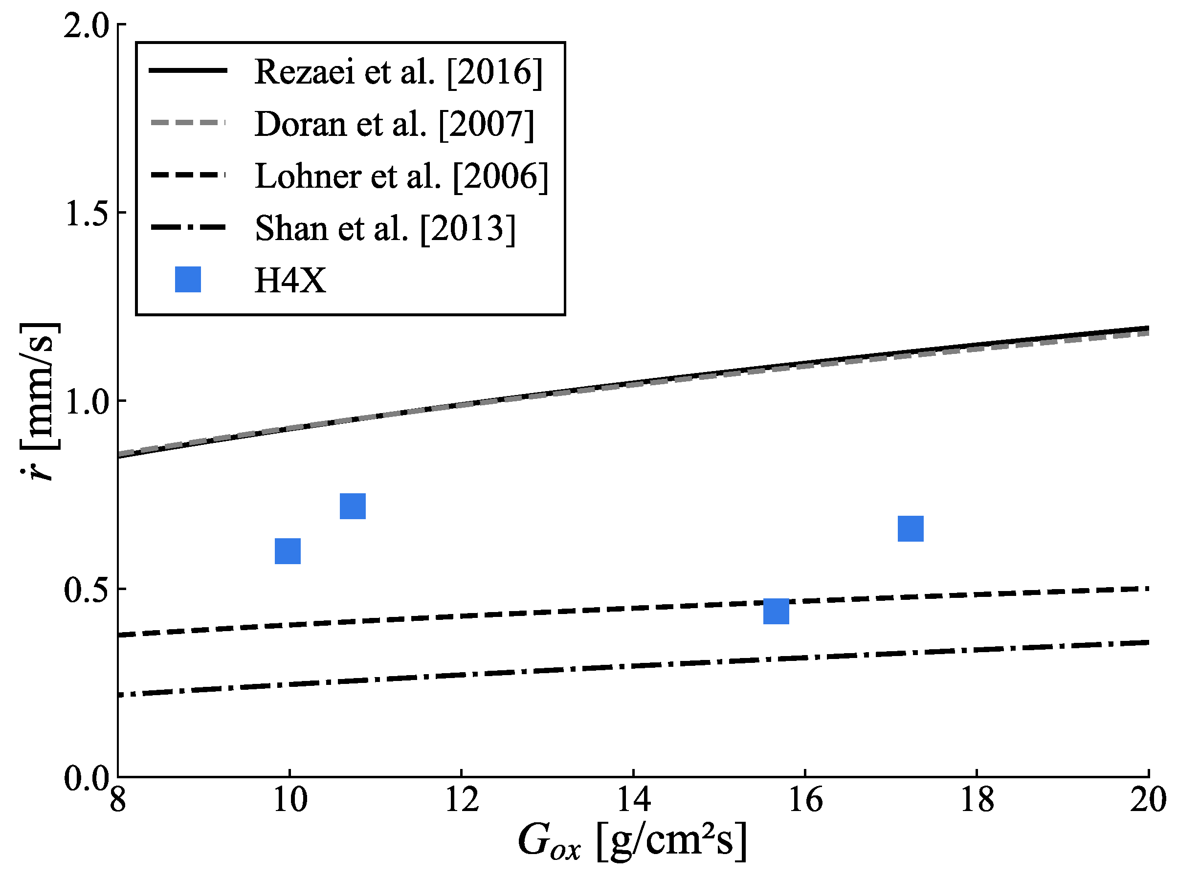
Figure 8 shows the fuel grain regression rates obtained from the four tests compared against data from the literature [8,31,32,33]. The regression rate curves from these data follow the empirical power law [7]:
r ˙ = a · G o x n
in which the coefficients a and n were obtained through experimental data. These experiments were conducted for the same combination of propellant and oxidizer at similar combustion chamber pressures and comparable O/F. The main differences to HYDRA 4X were the fuel grain geometry and injector type. Only fuel grains with single circular port geometries were tested in the references presented. The determined regression rates from four HYDRA 4X tests were located between the fitting curves of [8,31,32].

4.2. Impact of Engine Casing Material on Flight Apogee

The different designs of two HYDRA engines 3X and 4X were already discussed. Although there was a clear difference between engine performance data, structural changes were also made. A comparably heavy steel casing of HYDRA 3X was replaced by a CFRP coating to reduce engine mass. This consequently resulted in a higher apogee. On the other hand, using CFRP also meant higher effort in design, calculation, manufacturing, and costs. Therefore, it was interesting to evaluate the impact of this change on engine mass, total hybrid rocket mass, and on flight apogee. Thus, a parametric analysis for fundamental hybrid rocket pre-design was conducted. This was done by a MATLAB tool that was established during the STERN II program. It uses geometric and mass relations for estimating the design of sounding rockets. The tool calculates the engine data, such as propellant mass, mass flow, and burn time, based on a requested mean thrust and total impulse. The regression rate was assumed to be constant over burn time. The fuel mass flow was calculated according to a mean fuel grain surface and a constant oxidizer mass flow. The selectable fuel grain geometry was either a monoport or a star shape, and a conical nozzle was used. Two pressure tanks made from CFRP for oxidizer and pressure gas were calculated based on engine data. Residual rocket components like electronics or parachutes were estimated by the user. Physical relations for hybrid engines and flight mechanics (described in [1,7,34]) were used to estimate flight performance, using the mean thrust as a constant thrust profile over burn time. The tool analyzes first estimations on rocket design factors like engine performance, geometric dimensions, and flight parameters, such as flight apogee. The analysis is suited for rockets in an impulse range of 10 to 50 kNs and cell diameters of 100 to 180 mm . A parametric study was carried out for a basic rocket design with a constant cell diameter of 150 mm while the total impulse was increased continuously from 10 to 50 kNs . The rocket engine became larger (as more fuel was required) and longer. The engine structure mass and casing mass rose with increasing total impulse. The total impulse of an engine could be calculated by thrust F and engine burn time t b [1] according to Equation (19). This relation could be used here, since the design tool used a mean thrust value for calculations, even though the thrust profile was usually not constant for HRE.
I t o t = F · t b
The launch acceleration of the rocket shall be about 5 g at a rail length of 9 m . This results in a minimum thrust for an estimated rocket mass and a corresponding burn time. To characterize the relation between fuel and engine structure mass, two mass factors were introduced. Firstly, the relation factor f c m compares engine casing mass m c a s to fuel mass m f that can be accommodated by the engine. This factor shows how much casing mass is required for a defined fuel mass to reach a certain total impulse.
f c m = m c a s + m f m f
A second relation factor f e m is defined, which represents a comparison between overall engine mass m e (including fuel mass) and fuel mass. This factor links fuel mass to engine structure mass m s t r that includes casing and other structural engine components.
f e m = m e m f = m s t r + m f m f
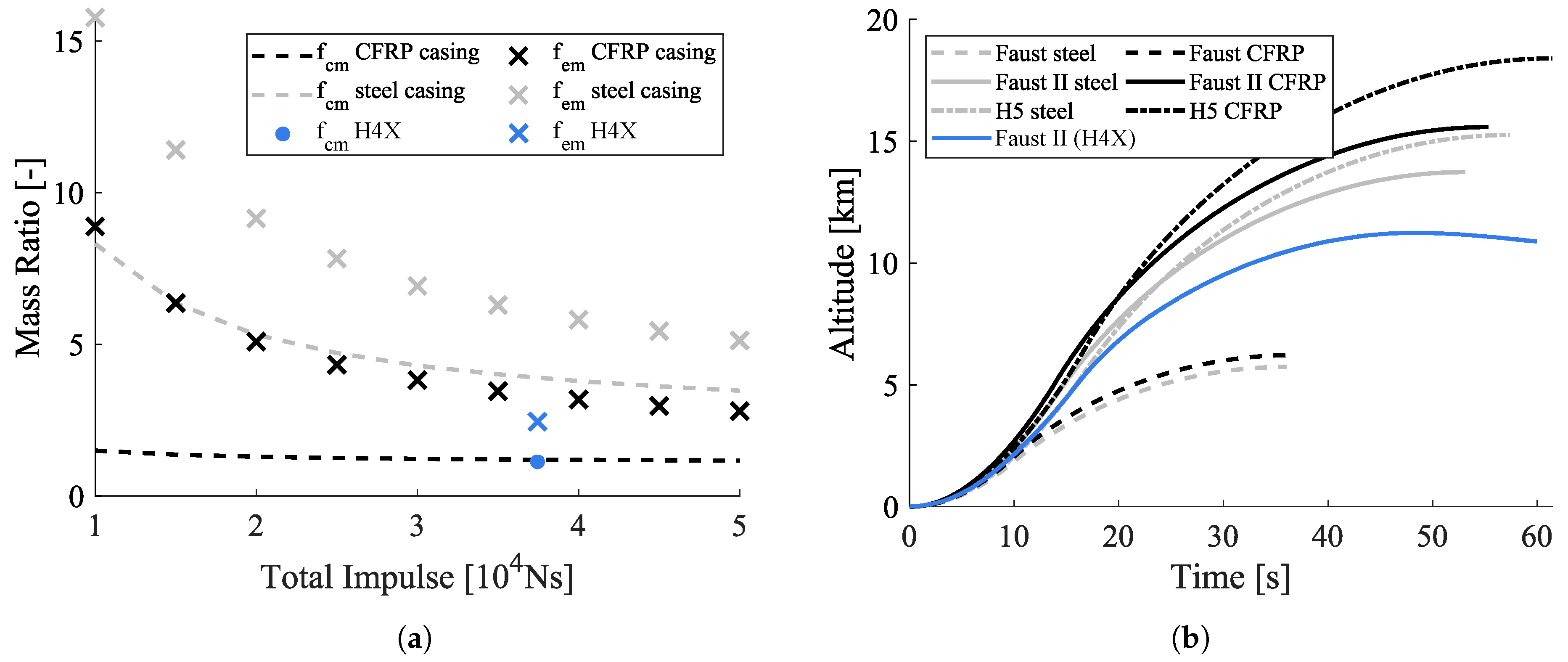
Using these engine parameters, a basic rocket design was developed and the results discussed. They were compared to the design parameters of the engine HYDRA 4X for the Faust II rocket that were presented. Figure 9a shows the defined mass relation factors as a function of total impulse in a range from 10 to 50 kNs .
Two main aspects can be derived from Figure 9a. A steel casing is heavier than a CFRP casing, but the relations between casing mass and fuel mass ( f c m ) change over the total impulse range. For smaller engines with a low total impulse of about 10 kNs , the weight of a steel casing is seven times higher than the respective fuel mass. This relation decreases with total impulse and shows a factor of about 3.5 for engines with a total impulse of 50 kNs . In comparison to that, f c m for a CFRP casing is nearly constant over the impulse range, where a mass factor of about 1.4 is reached. A second aspect addresses the total engine structure mass. It is derived from the casing (outer structure) and other structural components as presented. As Figure 9a shows for small engines ( 10 kNs ), the mass factor for overall engine mass f e m is at 15.7 for steel and 8.8 for CFRP casing material. This shows that the residual engine structure mass (disregarding the casing) cannot be neglected, although the mass factor f e m decreases with rising total impulse. The overall engine structure mass with a steel casing is about four times higher than the required fuel mass at an impulse of 50 kNs . In contrast, the structure mass with a CFRP casing is about twice as high as the accommodated fuel mass. Thus, the data showed that the engine structure mass was relatively high compared to the required fuel mass, especially, for a small impulse class. Less structure mass is needed relative to fuel mass for higher impulses. When using CFRP instead of a steel casing, the engine structure mass can be reduced by about 50% for the whole impulse range. The mass factor f c m for a steel casing shows a maximum for a small engine class, where the engine structure mass is very high compared to the fuel mass. Both mass factors decrease with increasing impulse. However, an engine with steel casing results in a mass twice as high as an engine with CFRP casing over the whole impulse range. The achieved values for the engine HYDRA 4X ( 35.5 kNs ) are added in blue color. A f c m value of 1.12 was in good accordance with the results of the parametric analysis. The engine mass factor f e m of 2.45 was lower than the analysis result of 3.3, which meant that less structure mass was needed for this engine than the parametric tool assumed.
Figure 9b shows the effect of casing material on flight apogee. Two existing (H3X, H4X) and one theoretical (H5) engine and subsequent rocket designs are presented in two versions: steel and CFRP, as presented in Table 7, where hybrid engine rockets for a range of impulses and rocket diameters are compared. For these designs, an approximated flight apogee was calculated to evaluate the casing mass impact. The flight trajectory is plotted until apogee, where the recovery system would be activated.
As Figure 9b shows, an apogee of 5.7 km for Faust with a hybrid engine using a steel casing was reached. This was similar to Faust flown in 2015 with an apogee of roughly 5.4 km . Therefore, the analysis provided reasonable results. An apogee difference for the two casing materials of about 500 m and a mass difference of about 2.2 kg were derived for Faust. A higher impact on apogee difference was observed for Faust II. Using a CFRP casing, Faust II was able to reach an altitude of 15.6 km (compared to 13.7 km when using a steel casing), which represented an apogee increase of about 14 % . The fully designed Faust II with a CFRP engine showed a higher mass than the pre-design (+6.7 kg), resulting in a lower apogee altitude of 11.2 km. The trend for an increase of apogee rose for the larger engine HYDRA 5 (cf. Table 7). By using a CFRP engine casing, an increase of 3.1 km ( 20.3 % ) was achieved compared to a steel casing. It was evident that a lighter CFRP engine casing was beneficial, especially for engines with higher total impulse and diameter values.

5. Conclusions and Outlook

The previous and current development activities of hybrid rocket engines at Technische Universität Braunschweig were examined. The design of the rocket engine HYDRA 3X was described, which was launched at the Esrange Space Center in 2015. It was a hybrid engine using nitrous oxide as the oxidizer and HTPB as the fuel. Based on this, a new engine HYDRA 4X was developed, which was designed for the Faust II rocket. The main design changes compared to HYDRA 3X were a higher total impulse and thrust and the CFRP casing material. The test bed and first test results of the new HYDRA 4X engine were shown. The design changes to iterate a requested engine performance were explained. In addition, the obtained fuel grain regression rates were compared to literature data.
To quantify the impact of different casing materials on rocket mass parameters, a parametric study was performed. First, casing and engine structure masses were compared to the fuel mass. It was shown that the fraction of structure mass to overall engine mass decreased over increasing total impulse, although the impact of casing material on rocket apogee altitude increased. The analysis was suited best for rockets with diameters between 100 and 180 mm and impulses between 10 and 50 kNs . A CFRP engine casing material showed a clear advantage over a heavy metal casing when only flight altitude was considered. However, other design, manufacturing, and cost parameters have to be taken into account to quantify the benefit of the material choice. In a next step, the parametric analysis will be extended to a wider range of impulses, and the pre-design of other rocket components like the recovery and electronics system will be refined.

Author Contributions

Conceptualization, F.H. and R.S.; investigation, R.S., L.K. and F.H.; data curation, L.K and R.S.; writing, original draft preparation, F.H. and L.K.; writing, review and editing, L.K., R.S., and E.S.; visualization, L.K. and F.H.; supervision, F.H.; project administration, E.S. All authors have read and agreed to the published version of the manuscript.

Funding

We acknowledge support by the German Research Foundation and the Open Access Publication Funds of the Technische Universität Braunschweig. This work was supported by the Federal Ministry of Economics and Technology on the basis of a decision by the German Bundestag (FKZ: 50 RL1752).

Acknowledgments

The authors thank the DLR Administration for conducting the STERN II program and the whole review board for assistance and advice. Special thanks are given to DLR Trauen for enabling conducting the engine tests.

Conflicts of Interest

The authors declare no conflict of interest.

Abbreviations

The following abbreviations are used in this manuscript:
Nomenclature
AArea (unit: m 2 )
aRegression rate coefficient
CCoefficient (unit: -)
dDiameter (unit: m)
FThrust (unit: N)
GOxidizer mass flow-to-free port area ratio (unit: g/cm 2 s)
fRelation factor (unit: -)
I s p Specific impulse (unit: m/s)
I t o t Total impulse (unit: Ns)
MMolar mass (unit: g/mol)
mMass (unit: kg)
m ˙ Mass flow (unit: kg/s)
nRegression rate coefficient, number (unit: -)
pPressure (unit: Pa)
Q ˙ Volume flow (unit: m 3 /s)
R Molar gas constant (unit: J/mol·K)
TThermodynamic temperature (unit: K)
tTime (unit: s)
Greek Symbols
η Efficiency (unit: -)
Γ Auxiliary function (unit: -)
γ Ratio of specific heats (unit: -)
ρ Density (unit: kg/m 3 )
Subscripts
aAmbient
bBurn
casCasing
cChamber
DDischarge
eEngine, exit (nozzle)
fFuel
oxOxidizer
pPort
strStructure
tThroat
thTheoretical
Abbreviations
TRLTechnical readiness level
HREHybrid rocket engine
DLRGerman Aerospace Center
STERNStudentische Experimental-Raketen
MORABAMobile Raketenbasis
IRASInstitute of Space Systems
ERIGExperimentalRaumfahrt-InteressenGemeinschaft
BMWiFederal Ministry of Economic Affairs and Energy
HYDRAHybrid Demonstrations-RaketenAntrieb
HTPBHydroxyl-terminated polybutadiene
N 2 ONitrous oxide
H 2 O 2 Hydrogen peroxide
LDPELow density polyethylene
PEpolyethylene
LOXLiquid oxygen
CFRPCarbon fiber-reinforced plastic
O/FOxidizer-to-fuel mass ratio
NASANational Aeronautics and Space Administration
CEAChemical Equilibrium with Applications
PIDPiping and instrumentation diagram

References

  1. Sutton, G.; Biblarz, O. Rocket Propulsion Elements, 7th ed.; John Wiley and Sons, Inc.: Hoboken, NJ, USA, 2001; pp. 27–38, 62–68, 77–82, 580. [Google Scholar]
  2. Li, X.; Tian, H.; Yu, N.; Cai, G. Experimental investigation of fuel regression rate in a HTPB based lab-scale hybrid rocket motor. Acta Astronaut. 2014, 105, 95–100. [Google Scholar] [CrossRef]
  3. Mazzetti, A.; Merotto, L.; Pinarello, G. Paraffin-based hybrid rocket engines applications: A review and a market perspective. Acta Astronaut. 2016, 126, 286–297. [Google Scholar] [CrossRef]
  4. Schmierer, C.; Kobald, M.; Fischer, U.; Tomilin, K.; Petrarolo, A.; Hertel, F. Advancing Europe’s Hybrid Rocket Engine Technology with Paraffin and LOX. In Proceedings of the 8th European Conference for Aeronautics and Aerospace Sciences (EUCASS), Madrid, Spain, 1–4 July 2019. [Google Scholar]
  5. Schmierer, C. Analysis of a Hybrid Propulsion Lunar Sample Return Mission. Ph.D. Thesis, University of Stuttgart, Stuttgart, Germany, 2019. [Google Scholar]
  6. Schmucker, R.H. Hybridraketenantriebe; Wilhelm Goldmann Verlag GmbH: Munich, Germany, 1972; pp. 22–24, 67–70. [Google Scholar]
  7. Barrère, M.; Schneider, W.K.; Roy, M.; Von Kármán, T. Raketenantriebe; Elsevier Publishing Co.: New York, NY, USA, 1961; pp. 66–72, 98, 112–114. [Google Scholar]
  8. Rezaei, H.; Soltani, M.R.; Mohammadi, A.R. Experimental Study of Fuel Regression Rate in a HTPB/N2O Hybrid Rocket Motor. Sci. Iran. 2018, 25, 253–265. [Google Scholar] [CrossRef] [Green Version]
  9. Chiaverini, M.J.; Kuo, K.K.; Peretz, A.; Harting, G. Regression-Rate and Heat-Transfer Correlations for Hybrid Rocket Combustion. J. Propuls. Power 2001, 17, 99–110. [Google Scholar] [CrossRef]
  10. Carmicino, C.; Scaramuzzino, F.; Sorge, A.R. Trade-off between paraffin-based and aluminium-loaded HTPB fuels to improve performance of hybrid rocket fed with N2O. Aerosp. Sci. Technol. 2014, 37, 81–92. [Google Scholar] [CrossRef]
  11. Sun, X.; Tian, H.; Li, Y.; Yu, N.; Cai, G. Regression rate behaviors of HTPB-based propellant combinations for hybrid rocket motor. Acta Astronaut. 2016, 119, 137–146. [Google Scholar] [CrossRef]
  12. Cheng, P.; Lia, Q.; Chen, H. Flow characteristics of a pintle injector element. Acta Astronaut. 2019, 154, 61–66. [Google Scholar] [CrossRef]
  13. Di Martino, G.D.; Malgieri, P.; Carmicino, C.; Savino, R. A simplified computational fluid-dynamic approach to the oxidizer injector design in hybrid rockets. Acta Astronaut. 2019, 129, 8–21. [Google Scholar] [CrossRef]
  14. Greatrix, D.R. Regression rate estimation for standard-flow hybrid rocket engines. Aerosp. Sci. Technol. 2009, 13, 358–363. [Google Scholar] [CrossRef]
  15. Hui, T.; Yijie, L.; Peng, Z. Transient simulation of regression rate on thrust regulation process in hybrid rocket motor. Chin. J. Aeronaut. 2014, 27, 1343–1351. [Google Scholar]
  16. Chiba, K.; Kanzaki, M.; Nakamiya, M.; Kitagawa, K.; Shimada, T. Conceptual Design of Single-Stage Launch Vehicle with Hybrid Rocket Engine for Scientific Observation Using Design Informatics. J. Space Eng. 2013, 6, 15–27. [Google Scholar] [CrossRef]
  17. Bozic, O.; Poppe, G.; Porrmann, D. An advanced hybrid rocket engine for an alternative upper stage of the Brazilian VLM 1 LEO-launcher. In Proceedings of the 65th International Aeronautics Congress, Toronto, ON, Canada, 29 September–3 October 2014. [Google Scholar]
  18. Karp, A.; Benito, J.; Nakazono, B.; Kim, H.; Shotwell, R.; Brandeau, E.; Vaughan, D.; Story, G. A Hybrid Mars Ascent Vehicle Design and FY 2016 Technology Development. In Proceedings of the IEEE Aerospace Conference, Big Sky, MT, USA, 4–11 March 2017. [Google Scholar]
  19. Tsohas, J.; Appel, B.; Rettenmaier, A.; Walker, M.; Heister, S.D. Development and Launch of the Purdue Hybrid Rocket Technology Demonstrator. In Proceedings of the 45th AIAA/ASME/SAE/ASEE Joint Propulsion Conference, Denver, CO, USA, 2–5 August 2009. [Google Scholar]
  20. Kawai, H.; Harada, J.; Oguro, J.; Banno, A.; Nakagawa, I. Launches of Hybrid Rockets with Wax Fuel. In Proceedings of the 49th AIAA/ASME/SAE/ASEE Joint Propulsion Conference, San Jose, CA, USA, 14–17 July 2013. [Google Scholar]
  21. Werner, R.; Knop, T.; Wink, J.; Ehlen, J.; Huijsman, R.; Powell, S.; Florea, R.; Wieling, W.; Cervone, A.; Zandbergen, B. Development and Performance of the 10 kN Hybrid Rocket Motor for the Stratos II Sounding Rocket. In Proceedings of the Space Propulsion 2016, Rome, Italy, 2–6 May 2016. [Google Scholar]
  22. DLR-Raumfahrtmanagement. STERN: Studentische Experimental-Raketen. 2012. Available online: https://www.dlr.de/rd/PortalData/28/Resources/dokumente/rl/STERN_Flyer.pdf (accessed on 13 January 2020).
  23. Becker, J.; Grefen, B.; Stoll, E. Results of the Leonis Project and Launch Campaign within the STERN Program. In Proceedings of the Deutscher Luft- und Raumfahrtkongress, Braunschweig, Germany, 13–15 September 2016. [Google Scholar]
  24. Schuettauf, K.; Stamminger, A.; Lappoehn, K. The STERN Project—Hand On Rockets Science for University Student. In Proceedings of the 23rd ESA PAC Symposium, Visby, Sweden, 11–15 June 2017. [Google Scholar]
  25. Rothe, D.; Hink, R. Faust Hybrid Rocket—Current Status. In Proceedings of the Deutscher Luft- und Raumfahrtkongress, Rostock, Germany, 22–24 September 2015. [Google Scholar]
  26. Dullo, C.M.U.; Hink, R. Experimental Analyses of the HTPB-Aluminum Mixtures for Hybrid Rocket Engines. In Proceedings of the Deutscher Luft- und Raumfahrtkongress, Stuttgart, Germany, 10–12 September 2013. [Google Scholar]
  27. Gamper, E.; Hink, R. Design and Test of Nitrous Oxide Injectors for a Hybrid Rocket Engine. In Proceedings of the Deutscher Luft- und Raumfahrtkongress, Rostock, Germany, 22–24 September 2015. [Google Scholar]
  28. Baade, M.; Hink, R. Design of a Nozzle for a Hybrid Rocket Engine Using an Explicit Finite-Volume Based Simulation for Heat Transfer. In Proceedings of the Deutscher Luft- und Raumfahrtkongress, Stuttgart, Germany, 10–12 September 2013. [Google Scholar]
  29. Hink, R. HYDRA 3 Hybrid Rocket Engine—Flight Version Test Results. In Proceedings of the Deutscher Luft- und Raumfahrtkongress, Rostock, Germany, 22–24 September 2015. [Google Scholar]
  30. Lemmon, E.W.; McLinden, M.O.; Friend, D.G. NIST Chemistry WebBook, NIST Standard Reference Database Number 69; Chapter Thermophysical Properties of Fluid Systems; National Institute of Standards and Technology: Gaithersburg, MD, USA, 2018.
  31. Lohner, K.; Dyer, J.; Doran, E.; Dunn, Z.; Zilliac, G. Fuel Regression Rate Characterization Using a Laboratory Scale Nitrous Oxide Hybrid Propulsion System. In Proceedings of the 42nd AIAA/ASME/SAE/ASEE Joint Propulsion Conference, Sacramento, CA, USA, 9–12 July 2006. [Google Scholar]
  32. Doran, E.; Dyer, J.; Lohner, K.; Dunn, Z.; Cantwell, B.; Zilliac, G. Nitrous Oxide Hybrid Rocket Motor Fuel Regression Rate Characterization. In Proceedings of the 43rd AIAA/ASME/SAE/ASEE Joint Propulsion Conference, Cincinnati, OH, USA, 8–11 July 2007. [Google Scholar]
  33. Shan, F.; Hou, L.; Piao, Y. Combustion performance and scale effect from N2O/HTPB hybrid rocket motor simulations. Acta Astronaut. 2013, 85, 1–11. [Google Scholar] [CrossRef]
  34. Andrea, L. A Mathematical Perspective on Flight Dynamics and Control; Springer: Berlin, Germany, 2017. [Google Scholar]
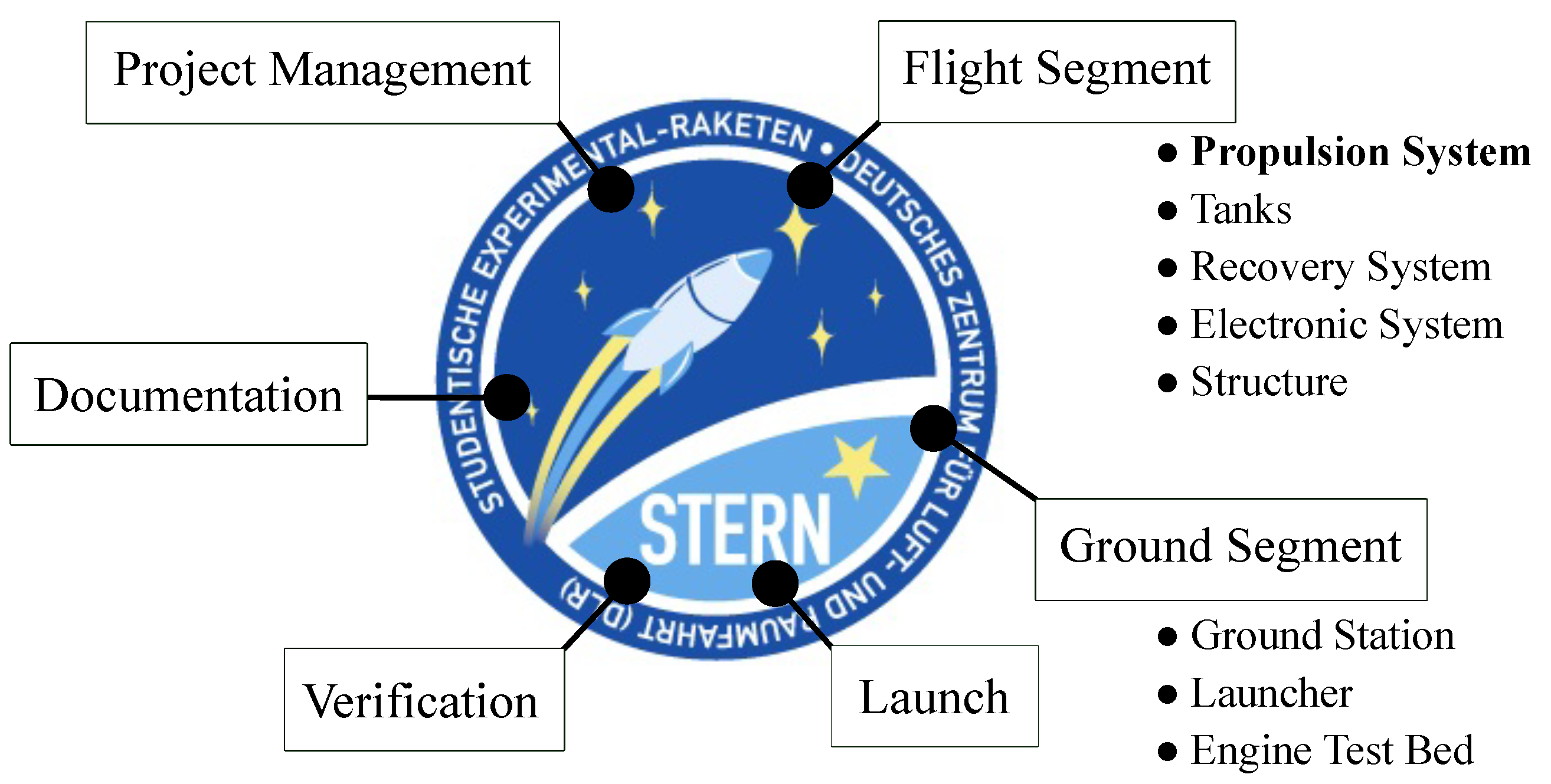
Figure 1. Overview of the STERN II project contents (STERN program logo [22]).
Aerospace 07 00057 g001
Figure 2. Design of the sounding rocket Faust.
Aerospace 07 00057 g002
Figure 3. Design of the engine HYDRA 3X.
Aerospace 07 00057 g003
Figure 4. Design of the HYDRA 4X engine and injector with injector channels and the diverting cone.
Aerospace 07 00057 g004
Figure 5. (a) Fluid plan of the fluid supply system; (b) Engine test bench with the engine HYDRA 4X.
Aerospace 07 00057 g005
Figure 6. Engine test data for HYDRA 4X-01 (a), 4X-02 (b), 4X-03 (c), and 4X-04 (d).
Aerospace 07 00057 g006
Figure 7. (a) Comparison of fuel grain geometry iterations; (b,c) Thickness of the HTPB fuel grain at star peaks in black and indentations. Distances were measured originating from the chamber wall. Symbols represent measurement points as indicated in (a), and lines resemble the corresponding mean values.
Aerospace 07 00057 g007
Figure 8. Comparison of fuel grain regression rates with literature data [8,31,32,33].
Aerospace 07 00057 g008
Figure 9. (a) Mass ratios f c m and f e m for steel and CFRP casing materials; (b) Flight trajectories until apogee altitude for three different rocket designs, again with steel or CFRP casing material
Aerospace 07 00057 g009
Table 1. The Faust rocket’s characteristics.
ParameterValue
Diameter 0.12 m
Length 3.2 m
Mass 24.1 kg
Altitude 5410.5 m
EngineHYDRA 3X
Table 2. Structural and performance characteristics of the engines HYDRA 3X and 4X.
ParameterSymbolHYDRA 3XHYDRA 4X
Overall lengthl 0.47 m 0.62 m
Overall diameterd 0.09 m 0.14 m
Fuel grain length l f 0.31 m 0.34 m
Post combustion chamber length l p o s t 0.05 m 0.10 m
Nozzle throat diameter d t 0.02 m 0.03 m
Nozzle area ratio A e / A t 5.064.97
Massm 5.7 kg 5.78 kg
Fuel mass m f 1.2 kg 2.57 kg
Casing mass m c a s 3.8 kg 0.31 kg
ThrustF 1.25 kN 2.25 kN *
Total impulse I t o t 12.5 kNs 35.55 kNs *
Chamber pressure p c 3 MPa 2.5 MPa *
* Design value.
Table 3. Input data and results of CEA calculation.
ParameterSymbolValue
Input parameter
Oxidizer to fuel mass ratio (-)O/F7
Combustion chamber pressure (MPa) p c 2.5
Nozzle exit pressure (MPa) p e 0.085
Output parameter
Temperature (chamber) (K) T c 3358.1
Molar mass of reaction product (chamber) (g/mol)M26.534
Ratio of specific heats (chamber) (-) γ c 1.1494
Ratio of specific heats (throat) (-) γ t 1.1474
Ratio of specific heats (exit) (-) γ e 1.2274
Specific impulse (m/s) I s p , C E A 2391.9
Table 4. Design data of HYDRA 4X.
ParameterSymbolValue
Oxidizer pressure (MPa) p o x 5
Combustion chamber pressure (MPa) p c 2.5
Mean density N 2 O (kg/m 3 ) ρ o x 915.85
Discharge coefficient (-) C D 0.497
Orifice diameter (mm)-0.8
Orifice length (mm)-5
Mass flow oxidizer (kg/s) m ˙ o x 0.93
Injector orifices (-)n55
Density HTPB (kg/m 3 ) ρ f 936.0
Regression rate (mm/s) r ˙ 0.66
Mass flow fuel (kg/s) m ˙ f 0.13
Outer diameter fuel grain (m) d f 0.13
Length fuel grain (m) l f 0.34
Burn time (s) t b 15.8
Nozzle exit pressure (MPa) p e 0.085
Nozzle area ratio (-) A e / A t 4.97
Momentum thrust coefficient (-) C F 0 1.47
Characteristic velocity (m/s) C * 1607
Throat diameter (m) d t 0.0295
Divergent nozzle length (m) l n o z z l e 0.07
Table 5. Overview of the design and measured parameters of HYDRA 4X-01 to HYDRA 4X-04.
Design ParameterH4X-01H4X-02H4X-03H4X-04
Fuel grain geometryGeometry v1Geometry v1Geometry v2Geometry v2
Injector36 orifices40 orifices40 orifices55 orifices
Post combustion chamber length 0.06 m 0.09 m 0.1 m 0.1 m
Measured parameter as mean over burn time
t b ( s ) 815.712.212.3
F ( kN ) 11.21.62.3
p c ( MPa ) 1.51.822.3
m ˙ f ( kg / s ) 0.080.10.130.12
r ˙ ( mm / s ) 0.440.630.720.66
p o x ( MPa ) 4.44.24.954.6
m ˙ o x ( kg / s ) 0.720.630.651.01
G o x (g/cm 2 s)15.71010.717.2
O / F ( - ) 8.756.358.4
Table 6. Parameters of two fuel grain geometries of HYDRA 4X.
H4X-01, 02H4X-03, 04
D130 mm
n86
α 25 12
β 70 48
Table 7. Comparison of rocket design parameters for three different engines with two different casing materials. Results presented in parentheses correspond to real flight data for Faust and CAD data for Faust II.
ParameterFaustFaust IIH5 Rocket
Cell diameter (m) 0.123 0.143 0.17
EngineHYDRA 3XHYDRA 4XHYDRA 5
Thrust (kN) 1.25 2.25 3
Total impulse (kNs) 12.50 35.55 50
Rocket mass (kg)Steel: 26.4 (24.1)
CFRP: 24.2
Steel: 44.3
CFRP: 39.6 (46.3)
Steel: 59.0
CFRP: 51.1
Apogee altitude (km)Steel: 5.73 (5.41)
CFRP: 6.22
Steel: 13.7
CFRP: 15.6 (11.2)
Steel: 15.3
CFRP: 18.4