Article

Lifetime Considerations for Electrospray Thrusters

1
Plasma & Space Propulsion Laboratory, UCLA Mechanical and Aerospace Engineering, 420 Westwood Plaza, Los Angeles, CA 90095, USA
2
LISA Microthruster Technology Lead, NASA Jet Propulsion Laboratory, California Institute of Technology, Pasadena, CA 91109, USA
*
Author to whom correspondence should be addressed.
Current address: UCLA Department of Mechanical and Aerospace Engineering, 420 Westwood Plaza, Los Angeles, CA 90095, USA.
Aerospace 2020, 7(8), 108; https://doi.org/10.3390/aerospace7080108
Submission received: 23 June 2020 / Revised: 21 July 2020 / Accepted: 24 July 2020 / Published: 29 July 2020
(This article belongs to the Special Issue Electric Propulsion)

Abstract

:
Ionic liquid electrospray thrusters are capable of producing microNewton precision thrust at a high thrust–power ratio but have yet to demonstrate lifetimes that are suitable for most missions. Accumulation of propellant on the extractor and accelerator grids is thought to be the most significant life-limiting mechanism. In this study, we developed a life model to examine the effects of design features, operating conditions, and emission properties on the porous accelerator grid saturation time of a thruster operating in droplet emission mode. Characterizing a range of geometries and operating conditions revealed that modifying grid aperture radius and grid spacing by 3–7% can significantly improve thruster lifetime by 200–400%, though a need for explicit mass flux measurement was highlighted. Tolerance analysis showed that misalignment can result in 20–50% lifetime reduction. In addition, examining the impact of electron backstreaming showed that increasing aperture radius produces a significant increase in backstreaming current compared to changing grid spacing. A study of accelerator grid bias voltages revealed that applying a reasonably strong accelerator grid potential (in the order of a kV) can minimize backstreaming current to negligible levels for a range of geometries.

1. Introduction

Electrospray thrusters offer advantages such as high thrust precision and a wide specific impulse range but have yet to demonstrate lifetimes that are attractive for many space missions [1]. Improving thruster lifetime has been noted as a key area of high specific impulse electrospray development by NASA [2]. Previous efforts investigating thruster performances and the lifetimes of field emission electric propulsion (FEEP) devices established trends associated with emitter–extractor separation and electrode impingement current [3,4,5]. The efforts identified geometric considerations crucial to reducing impingement current on the extractor electrodes, which was a key consideration for lifetime of the thruster.
The first successful in-space demonstration of electrospray propulsion technology was the Colloid MicroNewton Thruster (CMNT). The CMNT was developed by Busek Co., Inc and NASA Jet Propulsion Laboratory (JPL) for the European Space Agency (ESA) Laser Interferometer Space Antenna (LISA) Pathfinder mission as a technology demonstration of high thrust precision (100 nN) and low thrust-noise (100 nN · Hz 1 2 ) capability [6,7,8]. The demonstration was successful in establishing the CMNT’s thrust performance and precision, with seven of eight thrusters operating in flight for over 2400 h using 1-ethyl-3-methylimidazolium bis(trifluoromethylsulfonyl)imide (EMI-Im) as the propellant [9]. Results from the LISA Pathfinder mission represent one datum for thruster lifetime and seven instances in which the thruster lifetime is only known to be greater than the total operational time; how much greater is unknown. These results do not provide a sufficient understanding of the mechanisms responsible for thruster failure, nor an understanding sufficient for accurate estimation of thruster lifetime. Multi-year missions, such as the ESA LISA mission, require operational lifetimes in the order of 40,000 h [10], and hence require an understanding of the failure modes in electrospray devices. The lifetime estimation techniques proposed in this effort are an attempt to develop a framework for designing long-lifetime electrospray thrusters and to guide future experiments that seek to evaluate thruster lifetime.
The objective of this study was to identify, characterize, and examine numerous mechanisms crucial to understanding and predicting thruster lifetime. It has been proposed that overspray leading to grid (also referred to as electrode) impingement is the primary failure mechanism [11,12], resulting in eventual saturation of the porous accelerator grid, as shown in Figure 1. The effects of electrode geometry on overspray impingement and accumulation were therefore investigated and characterized. The results showed that overspray impingement is highly dependent on geometry but can be mitigated by judicious design, while misalignment tolerances must be carefully considered. Electron backstreaming current based on geometry was treated as a separate failure mechanism. Electron backstreaming analysis showed that increasing the aperture radius produces a significant increase in backstreaming current compared to changing grid spacing; however, reasonably high accelerator grid bias voltages can minimize backstreaming current to negligible amounts for a wide range of acceptable geometries and electron temperatures. Previously presented efforts towards these objectives have been expanded to include more comprehensive thrust and lifetime discussion and calculations, consideration of non-Gaussian plume profiles, and an analytical estimation of space charge effects on electron backstreaming [13].

2. Materials and Methods

2.1. Lifetime Limiting Mechanisms

Electrospray thruster lifetime depends on numerous design parameters and multi-tier life mechanisms, as outlined in Figure 2. Considerations for thruster design may be separated into three categories: operation and control, geometry, and material and propellant selection. Operation and control encompasses static and dynamic operation parameters, such as applied potentials, emitted flow rate, emitted current, thrust command variations, and startup and shutdown transients. The physical design parameters of the thruster, such as spacing between electrodes and thickness of the grids, are captured in the geometry, while the chemical and thermal response considerations are encompassed by material and propellant selection.
The ultimate failure mechanism for electrospray thrusters is shorting and power processing unit (PPU) failure, which can result from a variety of first and second tier mechanisms, as shown in Figure 2. The primary first-tier mechanism implicated in electrospray failure is overspray, which is defined as any emission that directly impinges on the grids. The impinging flux is dependent on static and transient emission properties related to operation and control of the thruster, such as emitter voltage, emitted flow rate, varying thrust commands, or startup and shutdown operations. As shown in Figure 1, the geometry of the electrodes determines the minimum line-of-sight half-angle that will result in grid impingement. Additionally, misalignment of the electrodes can result in increased flux to the grids. A detailed approach for characterizing overspray based on electrode geometry and misalignment is described in the following section. Propellant accumulation on the grids from overspray, coupled with sufficiently strong electric fields, can lead to emission of the opposite polarity back to the emitter, known as backspray. Further, insulation failure can occur due to propellant wetting of the insulator materials, resulting in electrode shorting. These two scenarios can be treated as second-tier mechanisms since they result from the first-tier mechanism of overspray. To delay the onset of backspray, porous grids can be used to absorb the impinging propellant [14]. Since grid saturation leads to backspray, the wicking rate and absorption capabilities/capacities of porous grids must be carefully considered. For example, pore size has been shown to have a strong effect on the emission from porous emitters [15] and is expected to have the same influence on backspray from porous grids.
In addition to propellant accumulation from overspray, other considerations can contribute to reduced lifetime. Flux of electrons towards the emitter due to the positive potential of the emitter, known as electron backstreaming (EBS), can induce electrochemical reactions in the propellant that can result in emitter damage and propellant decomposition near the emission site [16]. Chemical reactions due to the electric double layer can also contribute to propellant decomposition [17,18], leading to growth of undesirable byproducts on, or near, the emission surface. The propellant decomposition causes variations in fluid properties that affect the emission behavior, and therefore can lead to increased overspray. The accelerator grid is typically used to shield against EBS, which requires careful selection of operating voltage and geometry for successful implementation. Additionally, startup and operational transients can induce periods of unsteady emission that produce increased overspray emission [19,20].

2.2. Overspray

While many lifetime-limiting mechanisms exist, the primary concern for the electrospray thruster is overspray to the grids. Such overspray will coat the grids and can lead to shorting of the high potential electrodes. If porous grids are utilized, then the time to failure can be estimated as the time needed for overspray to effectively fill the grids. As detailed in Figure 3, grid impingement (fluxes 2 and 3 in Figure 3) can be categorized via two mechanisms that lead to propellant flux toward the extractor and accelerator grids. The primary mechanism is direct overspray (indicated by fluxes 4 and 5 in Figure 3), from the emission site, where the plume expansion begins, to the extractor and accelerator grids. The secondary mechanism is radial expansion of the plume due to repulsion and fragmentation of emitted charged species [21,22] and electric field divergence, with the resulting increase in radial motion in the emitter-accelerator region causing propellant flux to the grids (indicated by 6 and 7 in Figure 3). Propellant accumulation on the grids due to these two mechanisms coupled with a sufficiently strong electric field may lead to backspray (indicated by 8 and 9 in Figure 3).
Recent electrospray modeling efforts have sought to use molecular dynamics (MD) simulations to understand the behavior of electrosprays through simulation of the forces on each molecule. While MD provide useful results concerning the emission of ions from an electrified meniscus, high fidelity with experimental results has not been explicitly shown for cone-jet emission; for this reason we did not use results from MD simulations to inform this effort. The current state-of-the-art suggests that MD simulation is a valuable tool for predicting emission of ions and small clusters but does not adequately represent the cone-jet structure for droplet mode electrospray emission [23,24,25,26,27]. While ion emission may influence the lifetimes of electrospray devices, the majority of emission from the Taylor cone in cone-jet emission mode is in the form of droplets. Thus, any simulation technique must capture the behavior of the large, heavy droplets that dominate the plume. Simulating the emission process through MD would require modeling the cone-jet structure and hundreds of droplets. Through evaluation of the characteristic radius of the jet emerging from the Taylor cone, each droplet is estimated to contain in the order of 1000 EMI-Im molecules for the thruster in the presented effort [28]. Modeling droplet emission from a cone-jet structure requires including several orders of magnitude more molecules in a simulation than in a single droplet; the state-of-the-art is currently modeling up to tens of thousands of molecules [23,24,25,26,27]. Predicting electrospray behavior on the scale of the jet and droplets requires orders-of-magnitude increases in the capabilities for simulating large numbers of molecules. It is for this reason that the presented effort has focused on well-established empirical relations for the emission in cone-jet mode and experimental results for the distribution of droplets in the plume.
While plume expansion exists and its role in reducing thruster lifetime has been identified, in the present study we considered its effect to be negligible. Plume expansion was neglected due to the electrospray emission occurring in vacuum rather than in the atmosphere. Emission in the atmosphere has the effect of decelerating emitted droplets, increasing the space charge density and thus the repulsion between droplets [29]. Without drag in a vacuum, any initial spread in the plume causes the repulsion experienced by nearby droplets to decrease rapidly. This likely results in plumes largely without expansion after only a few jet diameters [22], or in the order of 20 n m for the thruster of interest to this study. Furthermore, variations in the velocities and specific charges of emitted droplets may cause intermittent expansion events in the plume [19]. These events were only considered as part of this study insofar as they contributed to a Gaussian-like distribution of charge in the plume. Numerical simulation of the plume as a collection of charged particles is sought as a means of understanding how local droplet interactions may lead to plume expansion [30,31].
Gamero-Castaño showed that current density profiles of capillary electrospray emission can be described using Gaussian-like distributions for EMI-Im [32]. Current density profile measurements of the CMNT reported in [33] also exhibit Gaussian-like distributions and indicate that any current beyond a 25 half-angle is minimal. However, current density profiles and mass flux profiles can deviate from each other as there is no expectation or requirement that a charge-mass ratio be uniform throughout the beam [34]. For example, lower charge-mass ratio droplets at high angles can result in significant mass flux while representing negligible current to the grids. Thus, while current collected by the grids can be an indicator of high impingement, mass flux is the specific mechanism that leads to grid saturation, which can result in backspray and/or insulator wetting. Therefore, minimizing mass flux, rather than current, to the grids is the principal factor in increasing the lifetimes of electrospray thrusters. Further, even with an extremely small mass flux, grid saturation can occur over long operation time.
In lieu of direct mass flux measurements, mass flux can be estimated from the current density through empirically determined scaling laws and experimentally determined constants. De La Mora [35,36] has previously shown that in cone-jet operating mode, emitted current can be empirically related to emitted flow rate, as described in Equation (1):
I B = C 1 Q 1 2 ,
where I B is the emitted beam current, C 1 is the flow rate coefficient, and Q is the volumetric flow rate.
The relationship between current and flow rate can be used to estimate thrust based on momentum conservation. The beam current is determined from the commanded thrust, T c o m , and emitter voltage, V, as shown in Equation (2):
T c o m = C 2 I B 3 2 ( V V T C ) 1 2 ,
V T C is the potential drop across the Taylor cone. The thrust coefficient C 2 ε ρ / γ κ , takes the nominal value 0.0319 μN · μ A 3 2 · V 1 2 [37], where ε is relative permittivity, ρ is mass density, γ is surface tension, and κ is conductivity. The analysis for determining the thrust and flow rate relations can be repeated for ion emission mode, yielding a relation similar to Equation (2) [38].
Mass flux, M ˙ , and current density, J , functions are now defined in spherical polar coordinates with the origin at the emitter tip, and then taken to be azimuthally symmetrical and spherically expanding. The mass flux and current density are only dependent on the polar angle, θ , given by Equations (3) and (4),
M ˙ = m ˙ ( θ ) r ^ ,
J = j ( θ ) r ^ ,
where m ˙ ( θ ) and j ( θ ) define the mass flux and current density angular distribution profiles per steradian respectively.
In the general case, m ˙ ( θ ) and j ( θ ) are defined by arbitrary functions f ( θ ) and g ( θ ) , which are scaled via F full and G full in Equations (5) and (6) to match the input flow rate and current.
m ˙ ( θ ) = Q ρ F f u l l f ( θ ) , where F f u l l = 0 π 2 π sin θ f ( θ ) d θ .
j ( θ ) = I B G f u l l g ( θ ) , where G f u l l = 0 π 2 π sin θ g ( θ ) d θ .
The exit velocity distribution, v e x i t ( θ ) , is determined from the charge and mass distributions together,
v e x i t ( θ ) = 2 j ( θ ) m ˙ ( θ ) V B = 2 V B I B F full Q ρ G full g ( θ ) f ( θ ) ,
(where V B = V V T C ), which is then combined with the mass flux to create a thrust element d T that can be integrated over the half-space to calculate the total thrust, T c a l c , described in Equation (8):
d T ( θ ) = m ˙ ( θ ) v ( θ ) cos θ ;
T c a l c = 0 π 2 m ˙ ( θ ) v e x i t ( θ ) cos θ 2 π sin θ d θ = π 2 V B I B Q ρ G full F full 0 π 2 f ( θ ) g ( θ ) sin ( 2 θ ) d θ .
For a given f ( θ ) or g ( θ ) , g ( θ ) or f ( θ ) respectively are parameterized and iterated until T c o m of Equation (2) and T c a l c of Equation (9) are within a specified range, thereby providing fully-defined estimates of the mass flux and current density distributions commensurate with empirical relations.
It is assumed that the flux to the extractor grid is many orders of magnitude smaller than the flux to the accelerator grid for geometries wherein the accelerator grid line-of-sight ( θ a c c ) is smaller than the extractor grid line-of-sight ( θ e x t ). The failure of the accelerator grid is therefore the primary lifetime concern; the onset of backspray is now defined as the time at which the accelerator grid saturates, t s a t , and is treated as the end-of-life criterion. t s a t is calculated via Equation (10).
t s a t = ρ V - c r i t m l o s s
where V - c r i t is the critical accumulated propellant volume at which the accelerator grid is saturated, and m ˙ l o s s is the rate of mass impingement on the accelerator grid, calculated as in Equation (11).
m ˙ l o s s = 2 π θ a c c π 2 m ˙ ( θ ) sin θ d θ .
V - c r i t is a tunable parameter which is a fraction of the open volume of the porous grid. In the present study V - c r i t is nominally taken to be the open volume of the porous grid, but future analysis can be further-informed by experiments that demonstrate the fill-fraction at which backspray occurs.
The algorithm for determining the time to grid saturation, t s a t , is outlined in Figure 4. Note that no restriction has been placed on the functional forms of f ( θ ) and g ( θ ) , beyond them being finite within the half-space.

2.3. Electron Backstreaming

Due to large grid apertures and the large positive potential at the emitter, electron backstreaming (EBS) from downstream of the thruster towards the emitter is likely. Similarly to ion thrusters, a negative voltage applied on the accelerator grid creates a potential barrier to minimize the backstreaming electron current [39]. An analytical process similar to that performed by Wirz et al. for the NSTAR thruster [39] is carried out for various geometries. The electron density is assumed to be equal to the charge density downstream of the accelerator grid, as specified by charge neutralization requirements.
An estimate of the space charge density, q s c , is analytically determined by dividing j ( θ ) Equation (6) by v e x i t ( θ ) Equation (7), at a spherical radius from the plume origin, r s p h , resulting in Equation (12),
q s c ( r s p h , θ ) = 1 r s p h 2 I B Q ρ f ( θ ) g ( θ ) 2 V B F full G full .
q s c is calculated to be ∼10−10 C · sr −1 on-axis for nominal operating conditions if a Gaussian plume profile is assumed.
The minimum potential along the axial path defines the potential barrier that retards electron backstreaming, as shown in Figure 5. The potential is a superposition of the applied field and space charge contribution. As shown in Equation (13),
V s c = 1 2 ϵ 0 I B Q ρ 2 V B 1 G full F full 0 θ a c c 0 r n e u t f ( θ ) g ( θ ) sin θ h s p 2 + r s p h 2 2 r s p h h s p cos θ d r s p h d θ ,
where h s p is the emitter-accelerator spacing, the space charge potential on axis at the accelerator ( V s c ) is calculated by summing the contributions of the charges in the plume, by integrating out to a neutralization distance ( r n e u t ) of 1000 times the spacing between the emitter and accelerator electrode (considered to be beyond the distance at which the plume would be neutralized by external sources). The resulting space charge potential is in the order of 2 V, which is more than an order-of-magnitude smaller than the minimum potential in the barrier and is thus ignored in further analysis.
For the purposes of lifetime estimation philosophy and obtaining a tractable analytical form, a Maxwellian distribution of electrons is assumed downstream of the thruster. This has been shown to be the case for ion thrusters [39] and provides a reasonable estimation for worst-case scenarios for electrospray thrusters, especially when experimental data to guide this process are not currently available. Alternative electron distributions, e.g., Druyvesteyn, are possible and shall be the subject of future research efforts. For the present effort, the effects of bulk electron energy on electron backstreaming were estimated by varying the temperature of a Maxwellian electron distribution function, as done by Wirz et al. [39] The portion of the Maxwellian electron distribution function with enough energy to overcome the potential barrier and stream into the thruster can be described by Boltzmann’s relation relating density to the exponential of local potential and distribution temperature. This one-sided electron flux to the emitter as a function of the radius from the centerline, Γ e r , is dependent on the temperature of the electrons, T e , the magnitude of the potential barrier along the axial path as a function of the radius from the centerline in cylindrical coordinates, ϕ m r ; the local electron number density, n e ; and mean thermal speed, c ¯ , as shown in Equation (14):
Γ e r = n e c ¯ 4 exp ϕ m r T e .
Integrating the flux from the centerline to the grid radius, r m a x , and assuming azimuthal symmetry, leads to the electron backstreaming current ( J E B S ) shown in Equation (15):
J E B S = 2 π e 0 r m a x r Γ e r d r .
This approach was utilized to determine the EBS current for a specific geometry. The implications of varying geometric parameters and bias voltages are discussed in the following section.

3. Results and Discussion

3.1. Overspray

Experimental data from CMNT ground testing [33] were used as the base current profile to inform the model. As the measured data were restricted to a half angle of 20 ; the values at larger half angles, crucial to determining grid impingement flux, were extrapolated by fitting Gaussian distributions to the data, shown in Figure 6a. The current density profile, g ( θ ) , was therefore set to a Gaussian distribution and parameterized by a width σ q ; and the mass flux function, f ( θ ) , was assumed to be Gaussian parameterized by width σ m . Iterating σ m to satisfy Equations (1), (2), and (8) yielded two solutions for the mass flux distribution, wherein one width ( σ m ) is larger than σ q and one smaller. Further analysis assumed the σ m > σ q case, as it provided a worse-case lifetime calculation (see Figure 6b), and has been preliminarily observed in simultaneously-measured mass flux and current density distributions of an electrospray plume [34].
To estimate the uncertainty in grid saturation time of this device, a full-scale error of 7.5% for the experimental dataset was assumed, which additionally encompasses a range of similarly-measured plume profiles [32,34,40,41,42,43,44]. Gaussian distribution fits based on the least squares method were determined for the best, nominal, and worst-case scenarios of the estimated spread of the current profile data. The resulting beam current profiles, described by the standard deviation of the Gaussian profile, σ q , are indicated in Figure 6a. At large angles, the assumed error resulted in uncertainty in current flux that exceeded the nominal values by over an order of magnitude, highlighting how data in the large half-angle regions, especially mass flux, can greatly improve our understanding of beam profiles associated with this emission mode and lifetime of electrospray devices.
The impact of the beam current profile on the accelerator grid saturation time is shown in Figure 6b to provide a comparison to experimental data. As the beam current profile grows in width (increased σ q ), the mass flux width σ m also grows, leading to increased impingement. The model indicates an expected lifetime of approximately 18,000 h for the nominal fit to the CMNT data (assuming a constant thrust command of 10 μ N ), with a range of 11,000–28,000 h for worst to best case scenarios. The broader beam current profile, described by a standard deviation of 8.00 , demonstrates the reduction in lifetime poor emission behavior can cause.
While it is tempting to work only with Gaussian distributions for f ( θ ) and g ( θ ) , there is no requirement that the plume takes such a form. Indeed, examples of non-Gaussian mass flux and current density have been reported [32,34,42]. The origins and implications of non-Gaussian plumes will be considered in a further publication, and further analysis in this paper assumes Gaussian plume profiles as described in Equation (16):
f ( θ ) = exp θ 2 2 σ m 2 .
The time to saturate the accelerator grid is dependent on a variety of factors, such as the accelerator grid aperture, the applied electric field, the spacing between the emitter and accelerator grid, and the open volume of the porous material, generally characterized by θ a c c and V - c r i t . The accelerator grid aperture and spacing between emitter and the accelerator grid can be collectively represented using θ a c c . Assuming the effects of plume expansion to be negligible, the impact of varying accelerator grid aperture and emitter-accelerator grid spacing is illustrated in Figure 7 using curves of constant geometric factors. Changes to geometry that do not affect beam profile, such as minor changes to θ a c c or varying the porosity or open volume of the porous grid, result in vertical translation between curves. Changes to beam profile, such as varying operational setpoints or applied electric field, cause shifts along the curve for a specified geometry.
It is evident that the best method for improving lifetime is better beam confinement, but geometry alterations to increase θ a c c can provide the desired lifetimes as well. While methods of improving beam confinement were not part of this effort, an analysis of accelerator grid geometry was performed to determine the implication of different approaches to θ a c c changes. As shown in Figure 8, a nominal geometry with θ a c c = 32 is assumed. Alternate geometries with larger θ a c c were then generated by increasing the accelerator grid radius, decreasing the spacing between the accelerator grid and emitter, and a combination of both changes. The geometry of the extractor in relation to the emitter was held constant in all cases. The potentials applied to the extractor and emitter were significantly larger than the potentials applied to the accelerator grid, as detailed in [9]. Therefore, small changes to the accelerator grid geometry did not substantially influence the field near the emitter and consequently the emission behavior. As a result, small changes to θ a c c were assumed not to affect emission behavior. As shown in Figure 9, relatively small changes to θ a c c yield a significant gain in grid saturation time. Decreasing the grid spacing and increasing grid aperture both increase grid saturation time similarly due to a nearly equivalent effect on θ a c c . Although neither change alone produces the desired lifetime, the combination of changes creates a geometry with a much larger θ a c c and resulting lifetime.
Large changes to grid spacing or aperture can impact parameters that contribute to lifetime considerations. For example, increasing the accelerator grid aperture radius decreases the volume of porous grid between emitters (septum). Decreasing the volume of porous material decreases the volume of propellant that can be accumulated before saturation and backspray occur ( V - c r i t ). In order to maintain the open volume in the septum, the emitters need to be shifted further apart, introducing potential design challenges. Decreasing grid spacing is not a simple solution either, as it will increase the electric field magnitude downstream of the extractor grid. The rise in electric field may expedite the onset of backspray emission. Additionally, changes to the electric field downstream of the emission region can lead to increased plume divergence [45] and increased fragmentation of droplets, both of which may result in increased mass flow to the grids.

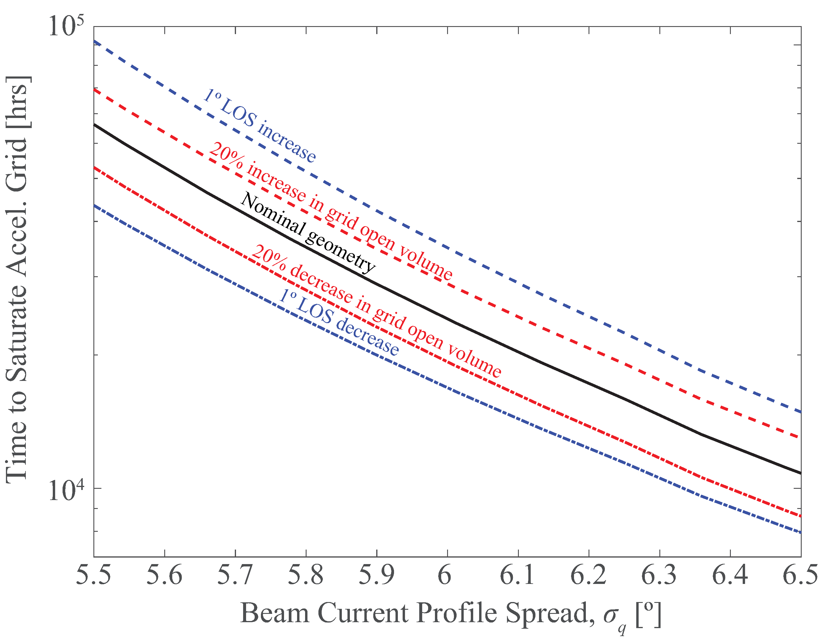
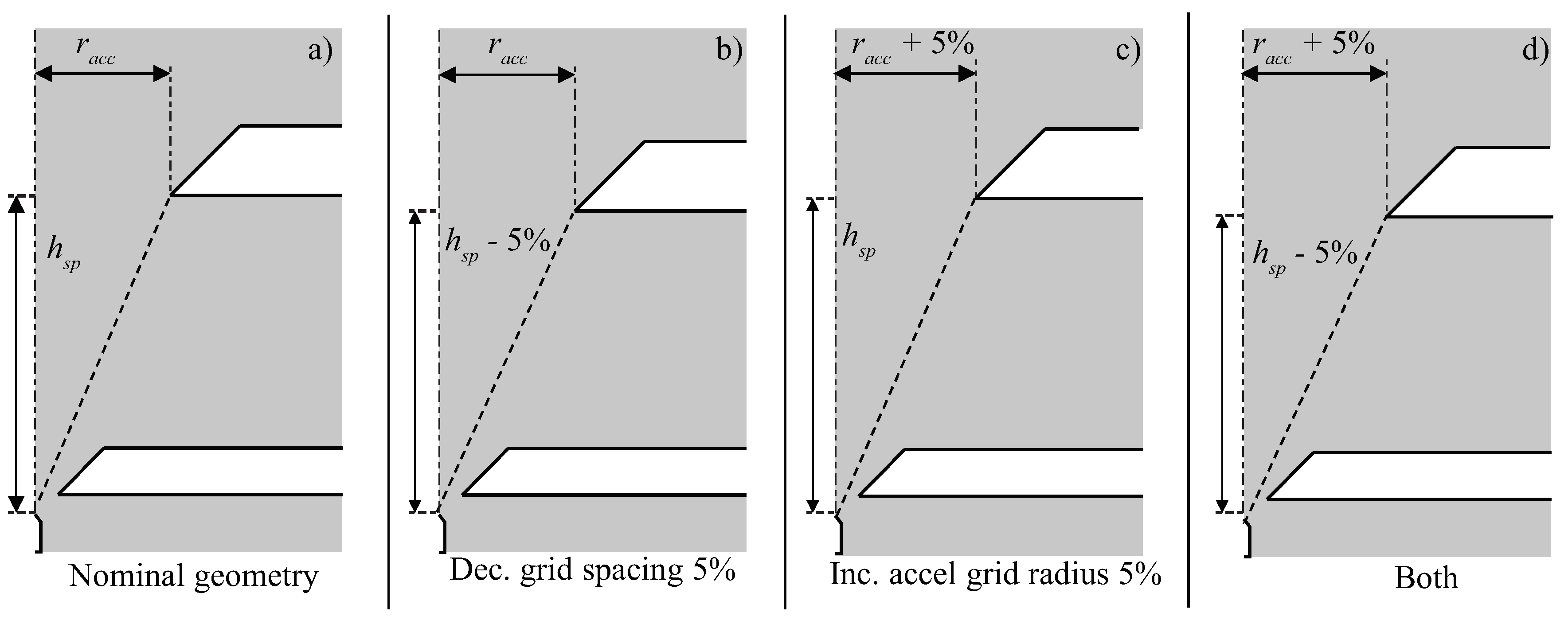
3.2. Misalignment and Tolerances

The significance of minuscule mass flux on the porous grids causes even small misalignments to have a substantial impact on lifetime. To estimate this effect, the overspray estimation approach was adapted to calculate intercepted flux in 3D, while maintaining the assumption that minor changes to accelerator geometry have negligible impacts on the plume characteristics. These assumptions approximate the case wherein the emitter is concentric with the extractor aperture but not necessarily concentric with the accelerator aperture. In this case, the θ e x t is constant while θ a c c is a function of the azimuthal angle around the emitter. Thus, a lateral offset in alignment of the emitter to the accelerator aperture decreases the line-of-sight angle in the direction of the offset while increasing the line-of-sight angle in the direction opposite to the offset. These two cases represent the extremes of θ a c c with all other azimuthal angles having an intermediate value of θ a c c . The overspray to the accelerator grid is estimated by calculating the overspray flow rate per azimuthal angle and integrating about the emitter axis. The decrease in lifetime with any lateral offset is a consequence of the non-linear decrease in flux with polar angle: a small decrease in θ a c c causes a large increase in the overspray flow rate. To transition from a single emitter to a multi emitter lifetime estimation, the overspray flow rate into the accelerator grid from each emitter is summed. The time required to fill the grid is the total volume in the grid divided by the total flow rate into the grid from all emitters together. As shown in Figure 10, accelerator misalignment can significantly reduce lifetime. For example, in a thruster containing nine emitters, introducing a 4% offset in the accelerator grid aperture from the emitter axis for just two emitters, can reduce thruster lifetime by 5%, while introducing this offset for all nine accelerator apertures can result in a 25% reduction of lifetime.
After investigating the reduction in accelerator grid saturation time due to accelerator misalignment, the expected degree of misalignment in an electrospray thruster was estimated using tolerance stackups. Multiple tolerances and misalignments were evaluated to determine the potential impacts on the lifetimes of thrusters with designs similar to the CMNT. For this analysis, dimensional variations were assumed to be independent of design tolerances [46]. The central accelerator aperture was assumed to be manually aligned to the central emitter, resulting in a degree of misalignment. The individual emitters all possessed an inherent misalignment with respect to the mounting structure from the mounting process. The accelerator grid manufacturing process determines positioning tolerance with respect to the mounting holes on the thruster and can result in an offset with respect to all emitters. Additionally, the mounting hole clearance can introduce a rotational offset. Each of these tolerances were considered together in order to determine the maximum resulting misalignment for each emitter in the thruster head.
The accelerator aperture alignment, mounting hole positioning, and mounting hole clearance were all assumed to have a 3.1% non-dimensional tolerance. The emitter position tolerance was approximated as 7.7%. For the purpose of establishing a distribution of misalignments, it was assumed that the features contributing to misalignment were produced by a process by which 95% of resulting features would be within the design tolerance. A single Gaussian distribution was used to approximate the stackup of all the tolerances. This resulted in a maximum misalignment of 3.1% for the center aperture and 7.5% for the side and corner apertures due to stackup of offsets. Assuming a realistic distribution of misalignment leads to an approximate 20.8% lifetime reduction. Assuming the worst case, wherein each aperture is at maximum misalignment, a 46.9% lifetime reduction is possible. The manufacturing, alignment, and handling processes of these devices are crucial to ensuring long lifetimes.

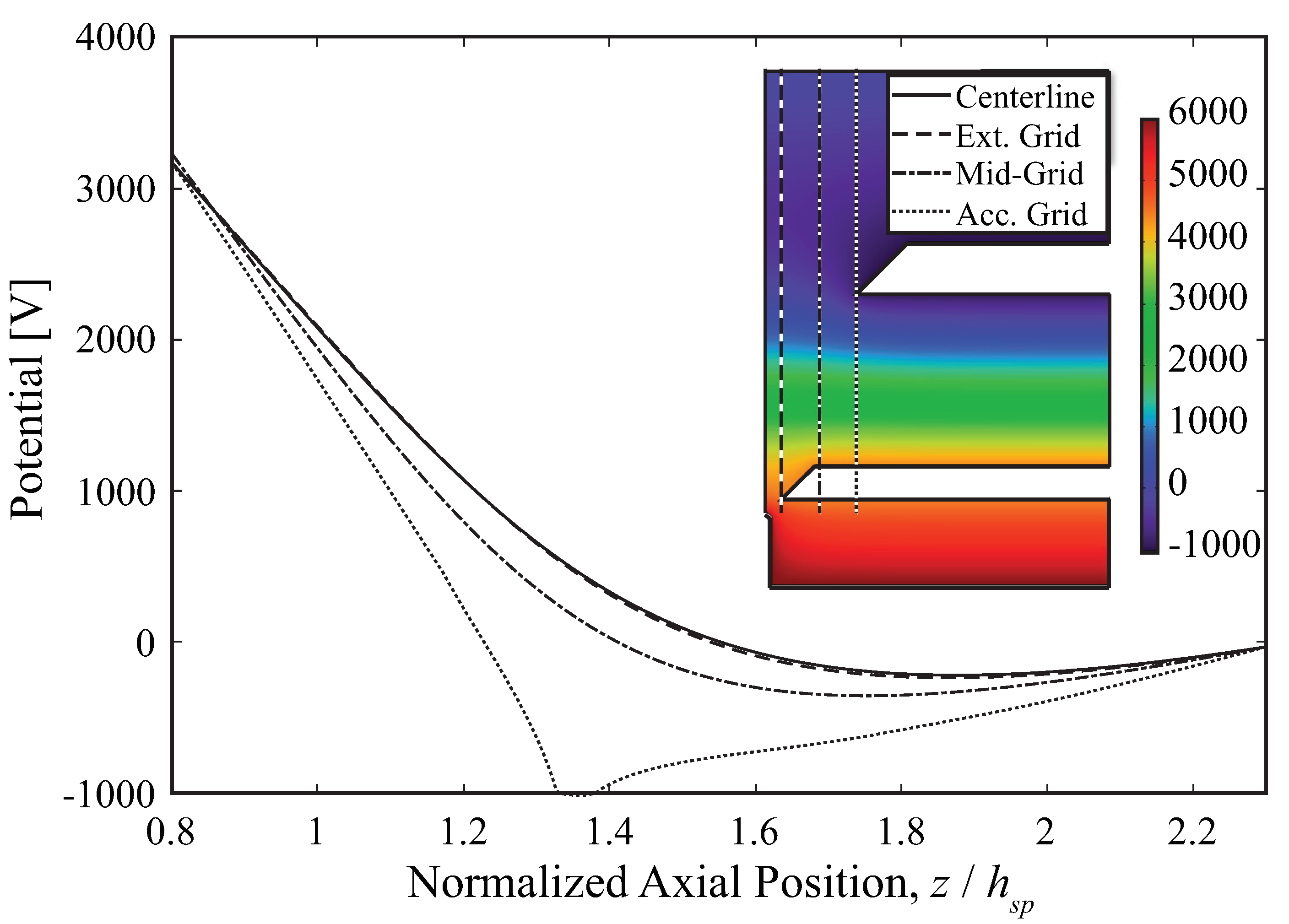
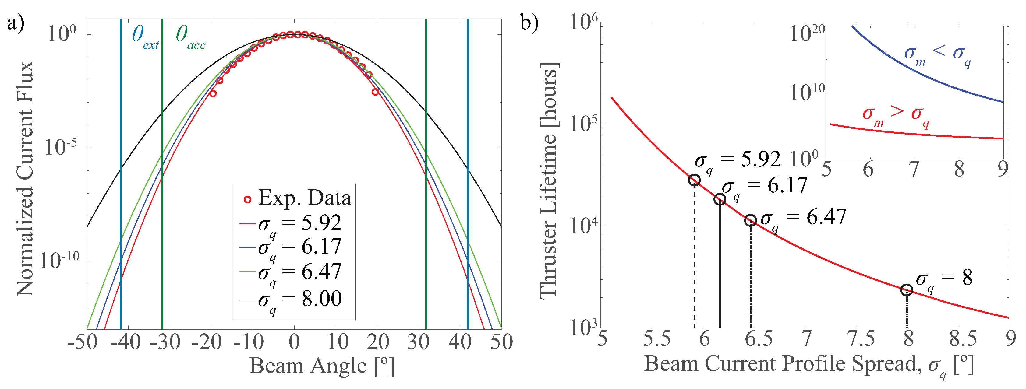
3.3. Electron Backstreaming

Emission properties and beam profile are dependent on propellant properties, specifically near the emitter tip. Chemical reactions due to electron backstreaming can impact propellant properties. The negative potential bias of the accelerator grid serves as a barrier against EBS. Figure 11 shows the current density and minimum potential as a function of distance from the centerline for geometries described in Figure 8, as computed using Equations (15) and (14) respectively. Similar to the EBS behavior in ion thrusters, the majority of electron flux is along the centerline of the emission axis. A strong radial gradient in minimum potential is effective at reducing backstreaming current. Increasing the grid aperture size increases the minimum potential in comparison to a smaller aperture size.
A more detailed explanation of the effects of increasing aperture radius is seen in Figure 12a. Increasing the aperture size produces a smaller minimum potential, which serves as the barrier against electron flux. As expected from Equation (14), the backstreaming current density increases non-linearly with increasing accelerator grid aperture. Figure 12b illustrates the impact of changing grid spacing on EBS flux. Decreasing grid spacing causes the emitter and extractor potential to dominate and effectively penetrate further downstream, increasing the minimum potential. As a result, the backstreaming current increases with decreasing grid spacing. As seen in Figure 11, and by comparing Figure 12a,b, increasing aperture radius is the larger concern for EBS effects because the current fraction increases at a larger rate than in comparison to the result of changing grid spacing.
Figure 13 shows the backstreaming current for varying bias voltages. Lower grid bias voltages leave the thruster susceptible to EBS in high electron temperature conditions. A strong accelerator grid bias ensures EBS current is negligible over the range of electron temperatures and reduces the impact of hotter electrons.

4. Conclusions

The impacts of lifetime-liming mechanisms on electrospray thrusters were quantified and evaluated. Overspray leading to grid impingement was treated as the primary failure mode, resulting in saturation of the porous accelerator grid. Grid geometry changes that increase line-of-sight angle without significantly affecting emission behavior were shown to considerably increase lifetime. In the context of potentially affecting electric field and beam profiles, accelerator grid aperture enlargement was shown to be more attractive than decreasing grid spacing. The significance of misalignment and tolerances on lifetime was presented. Emitter misalignment was shown to reduce lifetime significantly. Additionally, tolerance stackups from conservative estimates of manufacturing tolerances and misalignments were shown to reduce lifetime by approximately 20%, with a worst-case scenario of nearly 50%.
Electron backstreaming analysis showed that increasing the aperture radius produced a significant increase in backstreaming current compared to changing grid spacing. However, reasonably high accelerator grid bias voltages can minimize backstreaming current to negligible amounts for a wide range of geometries and electron temperatures. To optimize an emitter geometry for long operational lifetime, the effect of accelerator grid geometry on EBS and overspray accumulation must be considered together. The results show that in general, grid geometry changes that decrease accelerator grid impingement also increase EBS current, and vice versa. Balancing these effects represents a unique optimization problem to meet thruster requirements.
It is evident that minor differences in the mass profile shape and emitted flow rate can have strong implications on lifetime. Therefore, the effects of temperature variation must be accounted for. For example, the thrust coefficient relating operational parameters to thrust is dependent on ionic liquid properties, which are sensitive to temperature. Using current profile measurements to investigate impinging flux regarding the porous grids requires accounting for temperature effects to ensure the emitted mass flow is not being overestimated. Additionally, the effects of temperature must be considered when accounting for fluid transport in the grids due to the dependence on viscosity and surface tension.
Fitting Gaussian distributions to existing current profiles yields high uncertainty in the wide half-angle regions, resulting in a broad range of lifetime predictions. Therefore, future work is needed to obtain mass flux profiles of the beam to better estimate accumulation at the grids. Furthermore, the electrospray operating mode is not always steady, and can result in periods of pulsating emission [19,20], especially during startup, shutdown, or changing operational setpoints. Understanding the frequency of unsteady emission events and avoiding unsteady emission modes are crucial factors in achieving long lifetimes. Additionally, secondary electron emission, variations in charge-mass ratio, and the possibility of backspray from the grids can affect lifetime.

Author Contributions

Conceptualization, A.T., P.L.W., A.L.C., J.K.Z., and R.E.W.; data curation, J.K.Z. and R.E.W.; formal analysis, A.T. and P.L.W.; funding acquisition, J.Z. and R.W.; investigation, A.T., P.L.W., and A.L.C.; methodology, A.T., P.L.W., A.L.C., J.K.Z., and R.E.W.; project administration, J.K.Z. and R.E.W.; resources, J.K.Z. and R.E.W.; software, A.T. and P.L.W.; supervision, J.K.Z. and R.E.W.; validation, A.T., P.L.W., and A.L.C.; visualization, A.T., P.L.W., and A.L.C.; writing—original draft, A.T. and A.L.C.; writing—review and editing, P.L.W., J.K.Z., and R.E.W. All authors have read and agreed to the published version of the manuscript.

Funding

This work was funded by grants from NASA/JPL award number 1580267:3, Air Force Research Laboratory award number 16-EPA-RQ-09, and NASA Space Technology Research Fellowship grant 80NSSC18K1194. A portion of the research was carried out at the Jet Propulsion Laboratory, California Institute of Technology, under a contract with the National Aeronautics and Space Administration (80NM0018D0004).

Acknowledgments

The authors thank Colleen Marrese-Reading, David Conroy, and Stephanie Leifer from NASA JPL, and Nathaniel Demmons and Daniel Courtney of Busek Co. for their insightful discussions.

Conflicts of Interest

The authors declare no conflict of interest. The funders had no role in the design of the study; in the collection, analyses, or interpretation of data; in the writing of the manuscript, or in the decision to publish the results.

References

  1. Blandino, J.J.; Martinez-Baquero, N.; Demetriou, M.A.; Gatsonis, N.A.; Paschalidis, N. Feasibility for Orbital Life Extension of a CubeSat in the Lower Thermosphere. J. Spacecr. Rocket. 2016, 53, 864–875. [Google Scholar] [CrossRef]
  2. NASA. NASA Technology Roadmaps, TA 2: In-Space Propulsion Technologies; 2.2.1.5 Electrospray Propulsion; Technical Report; National Aeronautics and Space Administration: Washington, DC, USA, 2015.
  3. Marrese-Reading, C.; Anderson, J.R.; Jung-Kubiak, C.; Greer, F.; Rouhi, N.; Wilson, D.; White, V.; Dickie, M.; Mueller, R.; Singh, V.; et al. Silicon Emitter Needle and Array Design for Indium Electrospray Arrays for Spacecraft Propulsion. In Proceedings of the 52nd AIAA/SAE/ASEE Joint Propulsion Conference, Salt Lake City, UT, USA, 25–27 July 2016; pp. 1–14. [Google Scholar] [CrossRef]
  4. Marrese-Reading, C.; Anderson, J.R.; Jung-Kubiak, C.; Polk, J.; Singh, V.; Yee, K.; White, V.; Wilson, D.; Bruneau, P.; Rouhi, N.; et al. Microfluidic Electrospray Propulsion (MEP) Thruster Performance with Microfabricated Emitter Arrays for Indium Propellant. In Proceedings of the 52nd AIAA/SAE/ASEE Joint Propulsion Conference, Salt Lake City, UT, USA, 25–27 July 2016; pp. 1–15. [Google Scholar]
  5. Tajmar, M.; Genovese, A.; Steiger, W. Indium field emission electric propulsion microthruster experimental characterization. J. Propuls. Power 2004, 20, 211–218. [Google Scholar] [CrossRef]
  6. Hruby, V.; Spence, D.; Demmons, N.; Roy, T.; Ehrbar, E.; Zwahlen, J.; Martin, R.; Ziemer, J.; Connolly, W.; Rhodes, S.; et al. ST7-DRS colloid thruster system development and performance summary. In Proceedings of the 44th AIAA/ASME/SAE/ASEE Joint Propulsion Conference & Exhibit, Hartford, CT, USA, 21–23 July 2008; pp. 1–32. [Google Scholar] [CrossRef]
  7. Demmons, N.R.; Lamarre, N.; Ziemer, J.K.; Parker, M.; Spence, D. Electrospray Thruster Propellant Feedsystem for a Gravity Wave Observatory Missions. In Proceedings of the 52nd AIAA/SAE/ASEE Joint Propulsion Conference, Salt Lake City, UT, USA, 25–27 July 2016; pp. 1–16. [Google Scholar] [CrossRef]
  8. Ziemer, J.K. Performance of Electrospray Thrusters. In Proceedings of the 31st International Electric Propulsion Conference, Ann Arbor, MI, USA, 20–24 September 2009; pp. 1–13. [Google Scholar]
  9. Ziemer, J.; Marrese-Reading, C.; Dunn, C.; Romero-Wolf, A.; Cutler, C.; Javidnia, S.; Li, T.; Li, I.; Franklin, G.; Barela, P.; et al. Colloid microthruster flight performance results from space technology 7 disturbance reduction system. In Proceedings of the 35th International Electric Propulsion Conference, Atlanta, GA, USA, 8–12 October 2017; pp. 1–17. [Google Scholar]
  10. Amaro-Seoane, P.; Audley, H.; Babak, S.; Baker, J.; Barausse, E.; Bender, P.; Berti, E.; Binetruy, P.; Born, M.; Bortoluzzi, D. Laser interferometer space antenna. arXiv 2017, arXiv:1702.00786. [Google Scholar]
  11. Ziemer, J.K.; Randolph, T.M.; Gamero-Castaño, M.; Hruby, V.; Connolly, W.; Demmons, N.; Ehrbar, E.; Martin, R.; Roy, T.; Spence, D.; et al. Flight hardware development of colloid microthruster technology for the space technology 7 and LISA missions. In Proceedings of the 30th International Electric Propulsion Conference, Florence, Italy, 17–20 September 2007; pp. 1–13. [Google Scholar]
  12. Ziemer, J.K.; Randolph, T.; Hruby, V.; Spence, D.; Demmons, N.; Roy, T.; Connolly, W.; Ehrbar, E.; Zwahlen, J.; Martin, R. Colloid Microthrust Propulsion for the Space Technology 7 (ST7) and LISA Missions. In AIP Conference Proceedings; American Institute of Physics: College Park, MD, USA, 2006; Volume 873, pp. 548–555. [Google Scholar] [CrossRef]
  13. Thuppul, A.; Wright, P.; Wirz, R.E. Lifetime Considerations and Estimation for Electrospray Thrusters. In Proceedings of the 2018 Joint Propulsion Conference, Cincinnati, OH, USA, 9–11 July 2018; p. 4652. [Google Scholar]
  14. Demmons, N.; Martin, R.; Hruby, V.; Roy, T.; Spence, D.; Ehrbar, E.; Zwahlen, J. Electrospray Device. U.S. Patent 7,932,492, 26 April 2011. [Google Scholar]
  15. Courtney, D.G.; Shea, H. Influences of porous reservoir Laplace pressure on emissions from passively fed ionic liquid electrospray sources. Appl. Phys. Lett. 2015, 107, 103504. [Google Scholar] [CrossRef] [Green Version]
  16. Terhune, K.J.; King, L.B.; He, K.; Cumings, J. Radiation-induced solidification of ionic liquid under extreme electric field. Nanotechnology 2016, 27, 375701. [Google Scholar] [CrossRef] [Green Version]
  17. Brikner, N.; Lozano, P.C. The role of upstream distal electrodes in mitigating electrochemical degradation of ionic liquid ion sources. Appl. Phys. Lett. 2012, 101, 193504. [Google Scholar] [CrossRef]
  18. Lozano, P.; Martínez-Sánchez, M. Ionic liquid ion sources: Suppression of electrochemical reactions using voltage alternation. J. Colloid Interface Sci. 2004, 280, 149–154. [Google Scholar] [CrossRef]
  19. Wright, P.L.; Thuppul, A.; Wirz, R.E. Life-Limiting Emission Modes for Electrospray Thrusters. In Proceedings of the 54th AIAA/ASME/SAE/ASEE Joint Propulsion Conference & Exhibit, Cincinnati, OH, USA, 9–11 July 2018; pp. 1–9. [Google Scholar] [CrossRef]
  20. Rosell-Llompart, J.; Grifoll, J.; Loscertales, I.G. Electrosprays in the cone-jet mode: From Taylor cone formation to spray development. J. Aerosol Sci. 2018. [Google Scholar] [CrossRef]
  21. Barrios-Collado, C.; Vidal-de Miguel, G.; Sinues, P.M.L. Numerical modeling and experimental validation of a universal secondary electrospray ionization source for mass spectrometric gas analysis in real-time. Sens. Actuators B Chem. 2016, 223, 217–225. [Google Scholar] [CrossRef] [Green Version]
  22. Lozano, P.; Martínez-Sánchez, M. Studies on the Ion-Droplet Mixed Regime in Colloid Thrusters. Ph.D. Thesis, Department of Aeronautics and Astronautics, Massachusetts Institute of Technology, Cambridge, MA, USA, 2003. [Google Scholar]
  23. Konermann, L.; Metwally, H.; McAllister, R.G.; Popa, V. How to run molecular dynamics simulations on electrospray droplets and gas phase proteins: Basic guidelines and selected applications. Methods 2018, 144, 104–112. [Google Scholar] [CrossRef]
  24. Borner, A.; Li, Z.; Levin, D.A. Prediction of fundamental properties of ionic liquid electrospray thrusters using molecular dynamics. J. Phys. Chem. B 2013, 117, 6768–6781. [Google Scholar] [CrossRef] [PubMed]
  25. Mehta, N.A.; Levin, D.A. Electrospray molecular dynamics simulations using an octree-based Coulomb interaction method. Phys. Rev. E 2019, 99, 033302. [Google Scholar] [CrossRef] [PubMed] [Green Version]
  26. Daily, J.W.; Micci, M.M. Ionic velocities in an ionic liquid under high electric fields using all-atom and coarse-grained force field molecular dynamics. J. Chem. Phys. 2009, 131, 094501. [Google Scholar] [CrossRef] [PubMed]
  27. Kim, D.Y.; Micci, M.M. Molecular dynamics simulations of a liquid gallium electrospray thruster. J. Propuls. Power 2013, 29, 899–905. [Google Scholar] [CrossRef]
  28. Gamero-Castano, M.; Fernandez De La Mora, J. Direct measurement of ion evaporation kinetics from electrified liquid surfaces. J. Chem. Phys. 2000, 113, 815–832. [Google Scholar] [CrossRef] [Green Version]
  29. Gamero-Castaño, M. The structure of electrospray beams in vacuum. J. Fluid Mech. 2008, 604, 339. [Google Scholar] [CrossRef] [Green Version]
  30. Grifoll, J.; Rosell-Llompart, J. Continuous droplets’ charge method for the Lagrangian simulation of electrostatic sprays. J. Electr. 2014, 72, 357–364. [Google Scholar] [CrossRef] [Green Version]
  31. Davis, M.; Collins, A.L.; Wirz, R.E. Electrospray Plume Evolution Via Discrete Simulations. In Proceedings of the 36th International Electric Propulsion Conference, IEPC-2019, Vienna, Austria, 15–20 September 2019; Volume 590. [Google Scholar]
  32. Gamero-Castaño, M. Characterization of the electrosprays of 1-ethyl-3-methylimidazolium bis (trifluoromethylsulfonyl) imide in vacuum. Phys. Fluids 2008, 20, 032103. [Google Scholar] [CrossRef] [Green Version]
  33. Demmons, N.; Hruby, V.; Spence, D.; Roy, T.; Ehrbar, E.; Zwahlen, J.; Martin, R.; Ziemer, J.; Randolph, T. ST7-DRS mission colloid thruster development. In Proceedings of the 44th AIAA/ASME/SAE/ASEE Joint Propulsion Conference & Exhibit, Hartford, CT, USA, 21–23 July 2008; pp. 1–18. [Google Scholar] [CrossRef]
  34. Thuppul, A.; Collins, A.L.; Wright, P.L.; Uchizono, N.M.; Wirz, R.E. Spatially-Resolved Mass Flux and Current Measurements of Electrospray Plumes. In Proceedings of the 36th International Electric Propulsion Conference, Vienna, Austria, 15–20 September 2019; pp. 1–10. [Google Scholar]
  35. De La Mora, J.F.; Loscertales, I.G. The current emitted by highly conducting Taylor cones. J. Fluid Mech. 1994, 260, 155–184. [Google Scholar] [CrossRef]
  36. Fernández de La Mora, J. The fluid dynamics of Taylor cones. Ann. Rev. Fluid Mech. 2007, 39, 217–243. [Google Scholar] [CrossRef]
  37. Demmons, N.R.; Hruby, V.J.; Courtney, D.; Ziemer, J.K.; Marrese-Reading, C. Ground and On-Orbit Thruster Performance Comparison for the Lisa Pathfinder Colloid MicroNewton Thrusters. In Proceedings of the 2018 Joint Propulsion Conference, Cincinnati, OH, USA, 9–11 July 2018; American Institute of Aeronautics and Astronautics: Reston, VA, USA, 2018; pp. 1–15. [Google Scholar] [CrossRef]
  38. Courtney, D.G.; Dandavino, S.; Shea, H. Comparing direct and indirect thrust measurements from passively fed ionic electrospray thrusters. J. Propuls. Power 2015, 32, 392–407. [Google Scholar] [CrossRef] [Green Version]
  39. Wirz, R.E.; Katz, I.; Goebel, D.M.; Anderson, J.R. Electron Backstreaming Determination for Ion Thrusters. J. Propuls. Power 2011, 27, 206–210. [Google Scholar] [CrossRef]
  40. Ryan, C.; Daykin-Iliopoulos, A.; Stark, J.; Salaverri, A.; Vargas, E.; Rangsten, P.; Dandavino, S.; Ataman, C.; Chakraborty, S.; Courtney, D.; et al. Experimental progress towards the MicroThrust MEMS electrospray electric propulsion system. In Proceedings of the 33rd International Electric Propulstion Conference, Washington, DC, USA, 6–10 October 2013. [Google Scholar]
  41. Prince, B.D.; Fritz, B.A.; Chiu, Y.H. Ionic liquids in electrospray propulsion systems. In Ionic Liquids: Science and Applications; ACS Publications: Washington, DC, USA, 2012; pp. 27–49. [Google Scholar] [CrossRef]
  42. Miller, S.W.; Prince, B.D.; Bemish, R.J.; Rovey, J.L. Electrospray of 1-Butyl-3-Methylimidazolium Dicyanamide Under Variable Flow Rate Operations. J. Propuls. Power 2014, 30, 1701–1710. [Google Scholar] [CrossRef] [Green Version]
  43. Ma, C.; Ryan, C.N. The Design and Characterization of a Porous-emitter Electrospray Thruster (PET-100) for Interplanetary CubeSats. In Proceedings of the 7th Interplanetary CubeSat Workshop, Paris, France, 29–30 May 2018. [Google Scholar]
  44. Collins, A.L.; Thuppul, A.; Wright, P.L.; Uchizono, N.M.; Huh, H.; Davis, M.J.; Ziemer, J.K.; Demmons, N.R.; Wirz, R.E. Assessment of Grid Impingement for Electrospray Thruster Lifetime. In Proceedings of the 36th International Electric Propulsion Conference, Vienna, Austria, 15–20 September 2019; pp. 1–17. [Google Scholar]
  45. Thompson, J.W.; Eschelbach, J.W.; Wilburn, R.T.; Jorgenson, J.W. Investigation of electrospray ionization and electrostatic focusing devices using a three-dimensional electrospray current density profiler. J. Am. Soc. Mass Spectrom. 2005, 16, 312–323. [Google Scholar] [CrossRef] [PubMed] [Green Version]
  46. Chandrupatla, T.R. Quality and Reliability in Engineering; Cambridge University Press: New York, NY, USA, 2009; Volume 2. [Google Scholar]
Figure 1. Electrospray emitter and electrode geometry with line-of-sight plumes.
Aerospace 07 00108 g001
Figure 2. Hierarchical failure tree for electrospray life.
Aerospace 07 00108 g002
Figure 3. Emission from an electrospray that passes through the accelerator grid produces thrust (1). Additional non-thrust emission pathways exist that lead to lifetime reduction (numbered).
Aerospace 07 00108 g003
Figure 4. Description of grid impingement life model detailing required inputs and the iterative process employed to determine a lifetime estimate.
Aerospace 07 00108 g004
Figure 5. Electric potential along various axial lines showing the potential well that retards backstreaming electrons. Inset: electric potential for nominal geometry with varying axial lines indicated.
Aerospace 07 00108 g005
Figure 6. (a) A range of Gaussian fits to CMNT current profile data assuming 7.5% full-scale error and a normal fit indicating a current profile outside full-scale error but within uncertainty in the high-angle region. θ a c c in the given case is 32 . (b) Life model predictions for thruster lifetime as a function of current profile standard deviation with data fits from (a) indicated. The inset shows the lifetime calculations for both values of σ m that satisfy Equation (8).
Aerospace 07 00108 g006
Figure 7. The effects of geometry changes, porous grid capacity, and beam shape (indicated by standard deviation) on accelerator grid saturation time.
Aerospace 07 00108 g007
Figure 8. Varying accelerator grid geometries demonstrating methods to increase θ a c c from (a) nominal configuration by (b) decreasing grid spacing, (c) increasing accelerator grid radius, and (d) a combination of spacing and radius changes. Extractor grid geometry was held constant in all configurations to ensure emission behavior was not affected.
Aerospace 07 00108 g008
Figure 9. The effects of changing the accelerator grid’s aperture radius and the spacing between the accelerator and extractor grids on time to saturate the accelerator grid.
Aerospace 07 00108 g009
Figure 10. Misalignment can result in accelerator grid aperture offset from the emitter’s centerline; the impact of accelerator aperture misalignment on accelerator grid fill time is shown.
Aerospace 07 00108 g010
Figure 11. Radial profiles of backstreaming current density and minimum potential for varying geometries. The majority of flux occurs through a small region near the centerline.
Aerospace 07 00108 g011
Figure 12. Electron backstreaming (EBS) current fraction and minimum centerline potential for varying (a) grid spacing and (b) aperture radius, normalized by nominal geometry conditions.
Aerospace 07 00108 g012
Figure 13. Electron backstreaming current fraction as a function accelerator grid bias voltage for varying electron temperatures.
Aerospace 07 00108 g013

