Article

Future Directions for Electric Propulsion Research

Department of Aerospace Engineering, University of Michigan, Ann Arbor, MI 48105, USA
*
Author to whom correspondence should be addressed.
Aerospace 2020, 7(9), 120; https://doi.org/10.3390/aerospace7090120
Submission received: 7 July 2020 / Revised: 5 August 2020 / Accepted: 17 August 2020 / Published: 20 August 2020
(This article belongs to the Special Issue Electric Propulsion)

Abstract

:
The research challenges for electric propulsion technologies are examined in the context of s-curve development cycles. It is shown that the need for research is driven both by the application as well as relative maturity of the technology. For flight qualified systems such as moderately-powered Hall thrusters and gridded ion thrusters, there are open questions related to testing fidelity and predictive modeling. For less developed technologies like large-scale electrospray arrays and pulsed inductive thrusters, the challenges include scalability and realizing theoretical performance. Strategies are discussed to address the challenges of both mature and developed technologies. With the aid of targeted numerical and experimental facility effects studies, the application of data-driven analyses, and the development of advanced power systems, many of these hurdles can be overcome in the near future.

1. Introduction

The use of electric propulsion (EP) for space applications is currently undergoing a rapid expansion. There are hundreds of operational spacecraft employing EP technologies with industry projections showing that nearly half of all commercial launches in the next decade will have a form of electric propulsion. In light of their widespread use, the thruster types that have fueled this expansion—moderately-powered (1–20 kW) Hall effect, electrothermal, and ion thrusters—arguably have now achieved “mature” operational status. Given that the previous decades of electric propulsion research have been directed at the proliferation of these thrusters, we must decide where to aim continued efforts now that this goal has been achieved. What are the remaining challenges related to the operation of mature technologies, and which new technologies should be explored, if any?
The goal of this article is to outline possible future directions of the field of electric propulsion by discussing the challenges faced by modern technologies. We begin with a brief overview of the concept of the “s-curve” to represent technology development cycles and to illustrate the different types of challenges the field currently faces. We next consider the research questions related to electric propulsion systems at different power levels. We conclude by summarizing the common challenges for EP devices and then reviewing strategies for overcoming these issues and quickening the pace of development for more immature technologies.

2. Types of Electric Propulsion

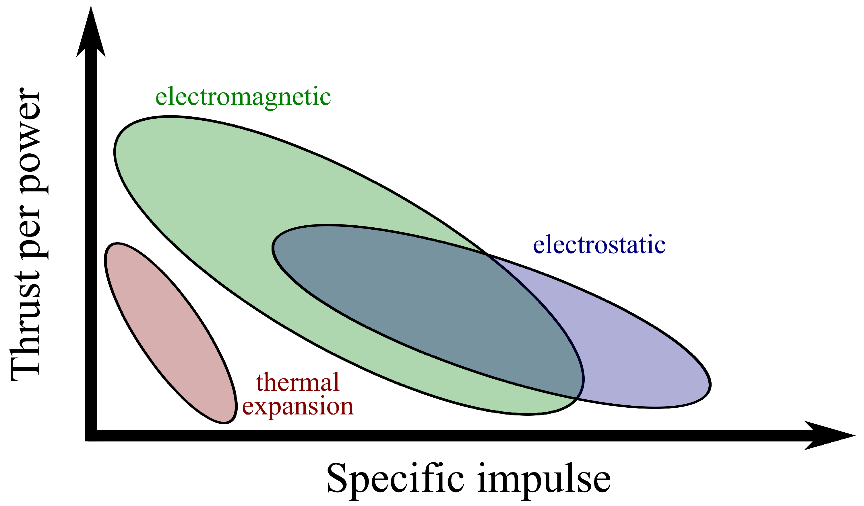
Figure 1 shows a trade space of thrust-to-power and specific impulse for the three major classes of electric propulsion. We have differentiated these by the mechanisms employed to generate thrust: thermal expansion, electrostatic, and electromagnetic. For concepts that rely on thermal expansion, a fluid is heated at high pressure and then expanded to low pressure, converting thermal energy to directed kinetic energy, thus generating thrust. In a conventional chemical propulsion system, the heat comes from combustion, and the expansion is guided by a physical nozzle. In an electrical propulsion system, the heat may be added, for example, via electrical heaters in a resistojet (RJ) or a plasma arc in an arcjet (AJ) paired with a physical nozzle, or inductively with radio frequency (RF) power paired with a magnetic nozzle (RF,MN). Electrostatic acceleration relies on the use of a time-invariant electric field to accelerate ions to produce thrust. Three common technologies that fall in this category are the gridded ion thruster (GIT), the electrospray (ES), and the Hall effect thruster (HET). In the first two, a potential is applied across electrodes to establish the accelerating electric field directly. In Hall thrusters, an electric field is self-consistently formed near the exit of the device without developing space charge. Concepts that employ electromagnetic acceleration include magnetoplasmadynamic (MPD), pulsed inductive (PIT), and pulsed ablative (or pulsed plasma, PPT) thrusters. In these devices, steady or time-varying electric and magnetic fields are used to accelerate a plasma via the Lorentz force.

3. Electric Propulsion Development Cycles

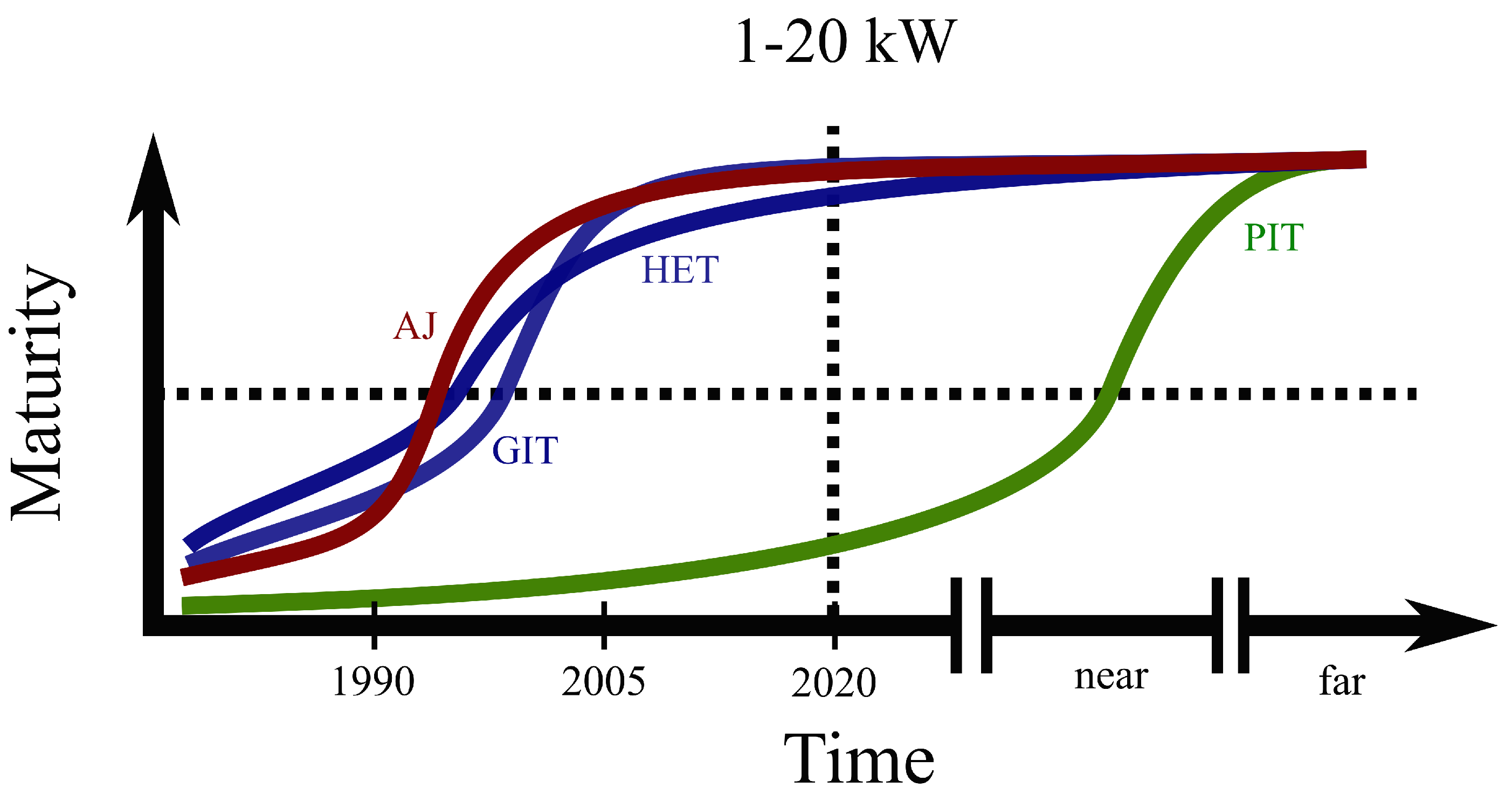
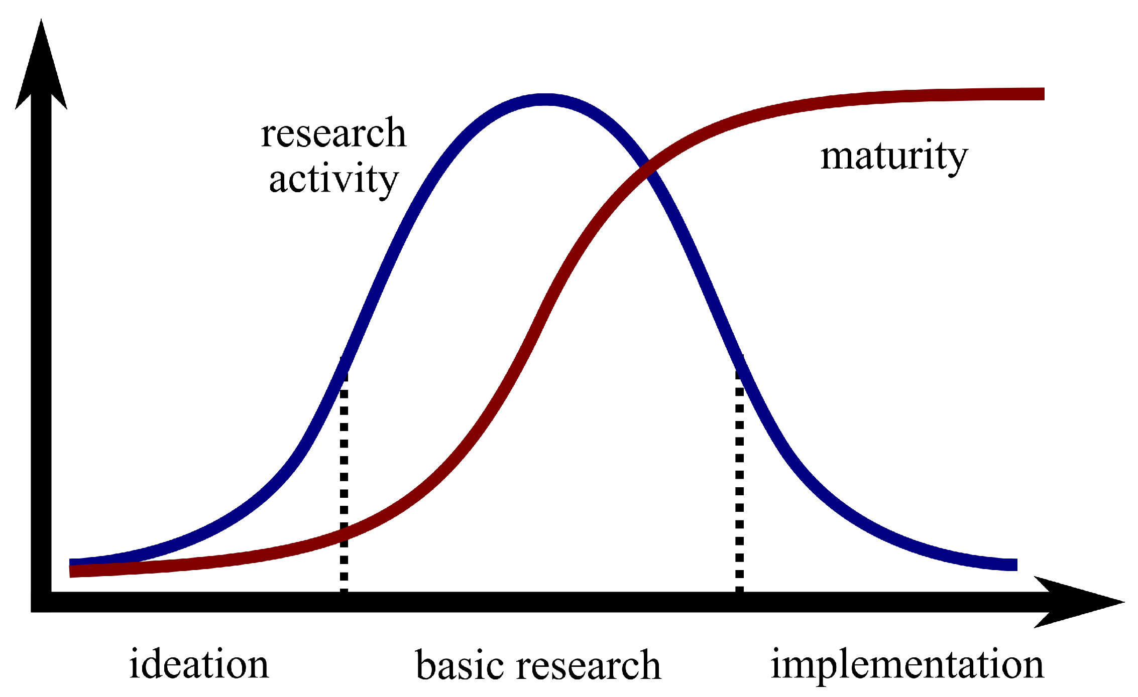
In order to represent the relative maturity of the disparate electric propulsion systems in a common framework, we adopt the convention of the “s-curve.” This is a widely used metric [1] that can represent the qualitative stages of a technology development cycle. As illustrated in Figure 2, a technology begins in the preliminary formulation stage where theoretical arguments or scaling laws may indicate that the technology promises new capabilities, and at this point, there may even be unoptimized prototypes. In the subsequent part of the cycle, increased resources are devoted to the technology to try to achieve the performance indicated by theory. In this state, there are dramatic leaps forward in performance and implementation that are achieved through basic research. At the latter part of the curve, the technology transitions from the laboratory to flight. This leads to the inflection point in the curve where the technology approaches its theoretical limits in performance. To be sure, the plateau of the curve does not mean that the need for fundamental research ceases, but rather, the technical challenges no longer directly pertain to dramatic performance improvements. Instead, the remaining challenges stem from the operational use of the technology, e.g., trying to increase the lifetime, understanding the interaction of the thruster with its spacecraft, or improving testing reliability.
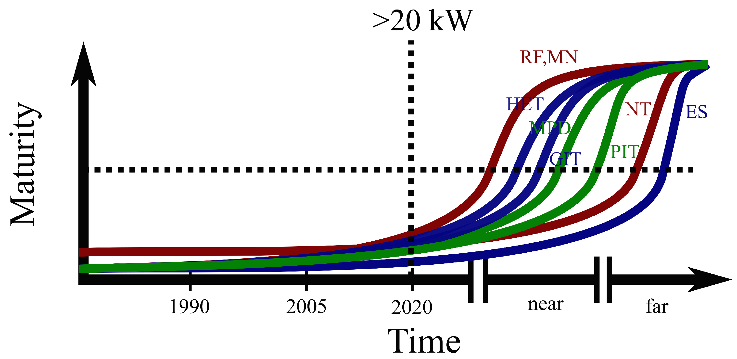
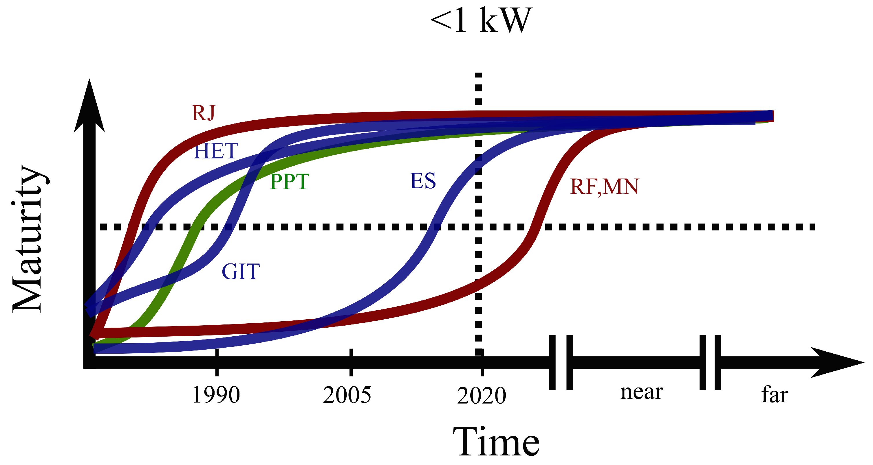
Throughout this article, we will present s-curves for various technologies at different power levels, namely Figure 3, Figure 8 and Figure 13. Therein, we show “maturity” as a function of time. To make these plots more quantitative, we pin the inflection point of the curve to the year at which three instances of a technology have flown on non-demonstration missions, according to [2]. We do this as a replacement for a more rigorous metric like technology readiness level, since assessing that quantity precisely is difficult for many immature technologies. In this way, the shape of the s-curve is largely qualitative, but the inflection is based on historical data. We categorize the s-curves respectively into low-power (<1 kW), moderate-power (1–20 kW), and high-power (>20 kW) concepts. We include gridded ion, magnetoplasmadynamic, Hall effect, pulsed inductive, electrospray, RF magnetic nozzle, and nuclear thermal (NT) thrusters. We additionally depict s-curves for common electrothermal devices (resistojets and arcjets) as examples of technologies that have been mature and flight-ready for many decades. We forgo any detailed discussion of them due to this maturity and the fact that the technical challenges they face are not representative of most other modern EP systems. Some technologies like Hall effect thrusters appear as multiple curves to reflect the parallel research efforts in developing these systems at different power levels, which often face distinct challenges worthy of a separate discussion. Finally, it is important to note that these curves are meant to reflect the typical, flight-ready state of a given class of thruster, not necessarily the state-of-the-art.
We rely on these s-curves because future research directions in the field depend on the technology in question and its corresponding level of maturity. The research questions of interest for more mature technologies like Hall effect, electrothermal, and gridded ion thrusters are different than those for the less mature systems like pulsed inductive thrusters. In the remainder of this article, we discuss the current state of electric propulsion, as well as its future direction. In doing this, we refer to the s-curves introduced in this section to describe the current obstacles and opportunities faced by the major forms of electric propulsion reviewed in Section 2.

4. Challenges for Electric Propulsion Development

The future of electric propulsion is mainly pushing in two directions: increasing the specific impulse and longevity of high-power technologies and improving the efficiency and reliability of low-power technologies. In the former, thrusters with longer lifespans and greater “fuel economy” will enable new deep space science missions, and thus are of primary interest to civilian institutions. In the latter, dropping launch vehicle costs has ignited interest in small-scale satellites and constellations for both commercial and scientific near-Earth applications. Naturally, a low-power electric propulsion solution is sought for this new wave of satellites. We discuss in the following the existing technologies that meet these developing needs at different power levels, focusing on the challenges they face and the solutions currently being developed.

4.1. Low-Power Thrusters

With the recent popularity and increasing affordability of small satellites, the need for propulsion systems that accommodate modest power budgets has grown. As these spacecraft generally also have little mass budget for propellant, electric propulsion is an attractive option. As a result, many EP technologies have been developed for sub-kilowatt systems or have been downsized to this power level. We depict notional s-curves for many of these types of devices in Figure 3.

4.1.1. Sub-Kilowatt Hall Thrusters

In Figure 3, the s-curve for Hall thrusters inflected several decades ago and has been progressively maturing since then. Traditionally, Hall effect thrusters have been operated above 500 W to maintain moderate current densities while minimizing the ratio of wetted surface area to volume of plasma. For magnetic field topographies that have field lines intersecting the channel walls nearly perpendicularly, the walls serve as an energy sink that stymies the development of a narrow, hot acceleration region to which this technology owes its efficiency. For this reason, most modern, high-performance Hall thrusters that are flown tend to be >1 kW. Moreover, until recent decades, the demand for very low-power Hall thrusters has been weak since these thrusters were often first used for satellite stationkeeping with >1 kW available. Historically, however, there are many notable development efforts that have focused on sub-kW devices, including the groundbreaking development of the Fakel Stationary Plasma Thruster family [3], the Central Research Institute of Machine Building (TsNIIMASH) D-55 Thruster with Anode Layer (TAL) [4], the Safran PPS series of thrusters [5,6], and the Busek BHT family [7]. Figure 4, for example, shows a low-power Hall thruster throttleable down to nearly 500 W developed at the University of Michigan based on the SPT-70. The low-power entries in the SPT series of thrusters ultimately yielded the SPT-100, a moderate-power device (discussed in Section 4.2.1) that has been flown extensively (the first discussed in [8] and more recently [9]) and has been subject to considerable investigation. As shown in Figure 3, these early sub-kW Hall thrusters matured fairly rapidly several decades ago, yet the poor performance of these devices at very low-power (<100 W) due to geometric scaling issues still leaves room for advancement.
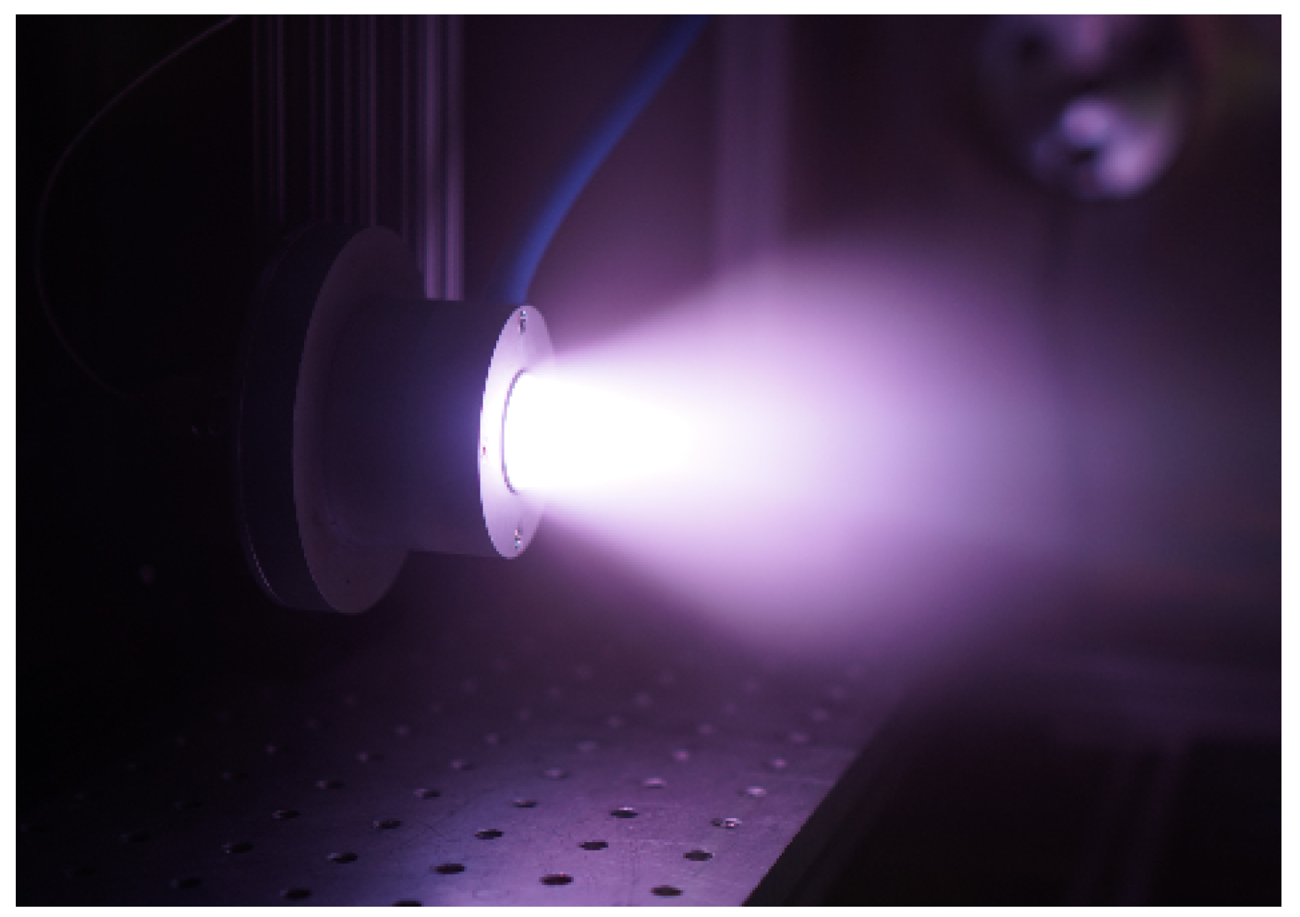
Recently, there has been renewed interest in very low-power Hall thrusters. For example, these devices are being developed privately by Orbion [10], Exoterra [11], Exotrail [12], Satrec Initiative [13], and Apollo Fusion [14], and considerable research on the magnetic shielding of this class of Hall thruster was performed by UCLA and the Jet Propulsion Laboratory with the Magnetically-Shielded Miniature (MaSMi) Hall thruster [15], shown in Figure 5 along with Exotrail’s 50 W Hall thruster.
The modern challenges for sub-kW Hall thrusters remain many of the obstacles identified for this technology by the 1990s. For example, the fundamental issue of growing wall losses with smaller geometries remains a problem, although magnetic shielding reduces these losses somewhat [16]. The power demands of the magnetic circuits of these devices also have proven challenging for integration on small spacecraft; designs incorporating permanent magnets have been explored [17] but are yet to fly. Finally, developing flight-ready but compact cathodes to use with sub-kW thrusters is a continuing issue, as many smaller Hall thrusters presently are paired with hollow cathodes rated to handle currents greatly exceeding the discharge current of these systems [18], needlessly complicating the spacecraft integration of these thrusters.

4.1.2. Sub-Kilowatt Gridded Ion Thrusters

Sub-kilowatt gridded ion thrusters appear relatively high on their s-curve in Figure 3, inflecting in the early 1990s. The development of low-power gridded ion thrusters has followed a similar trajectory to sub-kW Hall thrusters in that there was significant advancement several decades ago, and since then, there has been renewed interest in very low-power devices over the last decade. Although much of the early research on GITs focused on >1 kW devices (in fact, even the very first “Kaufman-style” GIT to fly was operated at 1.4 kW [19]), steady development of low-power devices like the Radio-frequency Ion Thruster (RIT) series originally developed by the University of Giessen [20] and JAXA’s Kiku ion thrusters [21] led to early inflection of the s-curve. Since then, there has been steady development of low-power GITs, like the 350 W microwave discharge gridded ion engines on JAXA’s Hayabusa mission, which in total accumulated over 25,000 h of operation in flight [22]. More recent very low-power GITs to be developed are the Busek BIT series [23], Astrium’s μ NRIT [24], and UCLA’s Miniature Xenon Ion (MiXI) thruster [25], shown in Figure 6.
Despite the recent development of these new systems, the majority of very low-power GITs remain less mature than higher power versions due to several major obstacles. Foremost is that ion thrusters require extensive power electronics to support the numerous electrodes involved in these designs. Naturally, then, significant development of more compact and efficient power processing systems is required to make sub-kW GITs practical. Second, the current that can be extracted from a gridded ion thruster is fundamentally space-charge-limited, such that for a given grid design, the beam current scales with the grid area of the device. Unlike in other technologies such as Hall thrusters where the current density can theoretically be increased for smaller thrusters to compensate for a lesser volume of plasma, this space-charge limitation constrains sub-kW GITs to low beam currents. Finally, gridded ion thrusters are often incidentally or intentionally “source-limited” rather than space-charge-limited [27], meaning that the ion flow into the grids is too small to realize the theoretical space-charge limit. Just as with Hall thrusters, for smaller GITs where wall losses may be exacerbated due to the small ratio of the volume-to-surface area, this source limiting may be more severe [28].

4.1.3. Electrosprays

For low-power electric propulsion, electrospray arrays are perhaps the most well developed and successful technology that can fulfill the niche of arbitrarily low power for near-Earth spacecraft. Unlike Hall thrusters and gridded ion thrusters that have poor geometric scaling, electrosprays have no increasing ionization cost with decreasing size – there is no ionization involved. For this reason, electrosprays can theoretically be scaled to microscopic sizes and thus perform well at low power. Reflecting this fact is the s-curve in Figure 3, in which electrosprays are moderately mature in the present day due to sustained research to take advantage of these perceived scaling benefits.
These devices were originally investigated in the 1960s, and although some of them were operated reportedly for thousands of hours, voltages as high as ∼10 kV were required to reach specific impulses competitive with gridded ion thrusters [29]. This was due to the use of solutions of ionic compounds as the propellant, which limited the electrospray operation to droplet extraction, requiring high voltages to break the propellant surface tension and adequately accelerate the heavy droplets. In the past few decades, interest in electrosprays has reignited with the increasing desire for fine thrust control, the push for low-power propulsion solutions for small satellites, and the realization that room-temperature ionic liquids or liquid metals allow for ion extraction, thus requiring lower voltages.
An electrospray system has been successfully used on the ST-7/LISA Pathfinder mission, in which twin four-head field emission electric propulsion (FEEP) units were able to fulfill the control, noise, and duration objectives of the mission [30]. However, the need for continued development of this technology was made clear by the various anomalies that arose during the mission: one thruster had a sluggish response time and current spikes, and another thruster developed a terminal short after 1670 h of operation [30]. Electrospray systems have also flown on various small satellites, including the Massachusetts Institute of Technology’s SiEPRO on multiple AeroCube spacecraft [31] and Enpulsion’s IFM Nano-Thruster [32].
The largest challenge for electrospray thrusters is arraying, which itself is obstructed by the poorly understood stability and failure modes of single emitters. Typical single-emitter systems consume ≪1 kW, so scaling them to practical power levels (∼100 W) requires fabricating and operating numerous emitters in an array. However, the manufacturing of these arrays can prove challenging, and the chance for terminal failure increases (examined in [33]), especially when the nature of the failure modes and the related instabilities are unclear.

4.1.4. Magnetic Nozzles

Like electrosprays, interest in microwave and RF thrusters as a practical electric propulsion solution has reignited in recent decades. The s-curve in Figure 3 depicts the relative immaturity of low-power RF nozzled thrusters until recently. As these devices have no plasma-wetted electrodes, they can be used with a variety of propellants; further, they can be easily scaled to low power due to the efficiency of inductive plasma generation. However, high performance (high specific impulse) versions of these devices are still at the lower end of the s-curve. Early work on these devices showed promising performance, but high specific mass due to the power electronics involved [34,35]. The intervening decades have seen a miniaturization and commodification of these electronics, such that RF nozzled thrusters are now being targeted for use on small satellites. Although an example of this technology has yet to fly, studies of magnetic nozzles are slowly improving their efficiency above single digits [36], and commercial developers are already validating flight units [37]. Yet, there are still many outstanding questions about the fundamental operation of these devices, the foremost being the detachment of electrons from magnetic field lines necessary for thrust generation [38,39,40]. Figure 7 shows an example of a modern laboratory microwave thruster that utilizes electron cyclotron resonance for plasma heating [41].

4.1.5. Pulsed Plasma Thrusters

Pulsed plasma thrusters (PPTs) are a simple form of electric propulsion that has been studied extensively theoretically and experimentally, leading to it presently being high on its s-curve in Figure 3. These devices strike an arc across a (typically) solid fuel and then accelerate the resulting plasma along parallel electrodes via the Lorentz force. This is accomplished in a straightforward manner by periodically charging and discharging a capacitor, usually with an igniter circuit involved to trigger the discharge.
Many of these devices have been developed, such as those by Austrian Research Centers GmbH [42], Mars Space Ltd. [43], Fotec GmbH [44], and Busek [45], and several have flown, starting with the Soviet Zond-2 mission [46] and more recently including Busek’s μ PPT on Falcon-Sat 3 [47] and several thrusters developed by Nanyang University and Kyushu Institute of Technology [48]. Yet, they are challenged still by the theoretical scaling limits to very low power and the lifetime of these devices, which necessarily strike high-current ablative arcs between electrodes.

4.2. Moderate-Power Thrusters

As Figure 8 shows, perhaps the most mature electric propulsion devices are those of moderate power, between 1 and 20 kW. Considering the availability of solar power on modern spacecraft, the strictures of flight-readiness, and the limitations of ground testing, most commercial and deep space missions utilizing electric propulsion in the next decade will rely on thrusters at this power level.

4.2.1. Hall Effect Thrusters

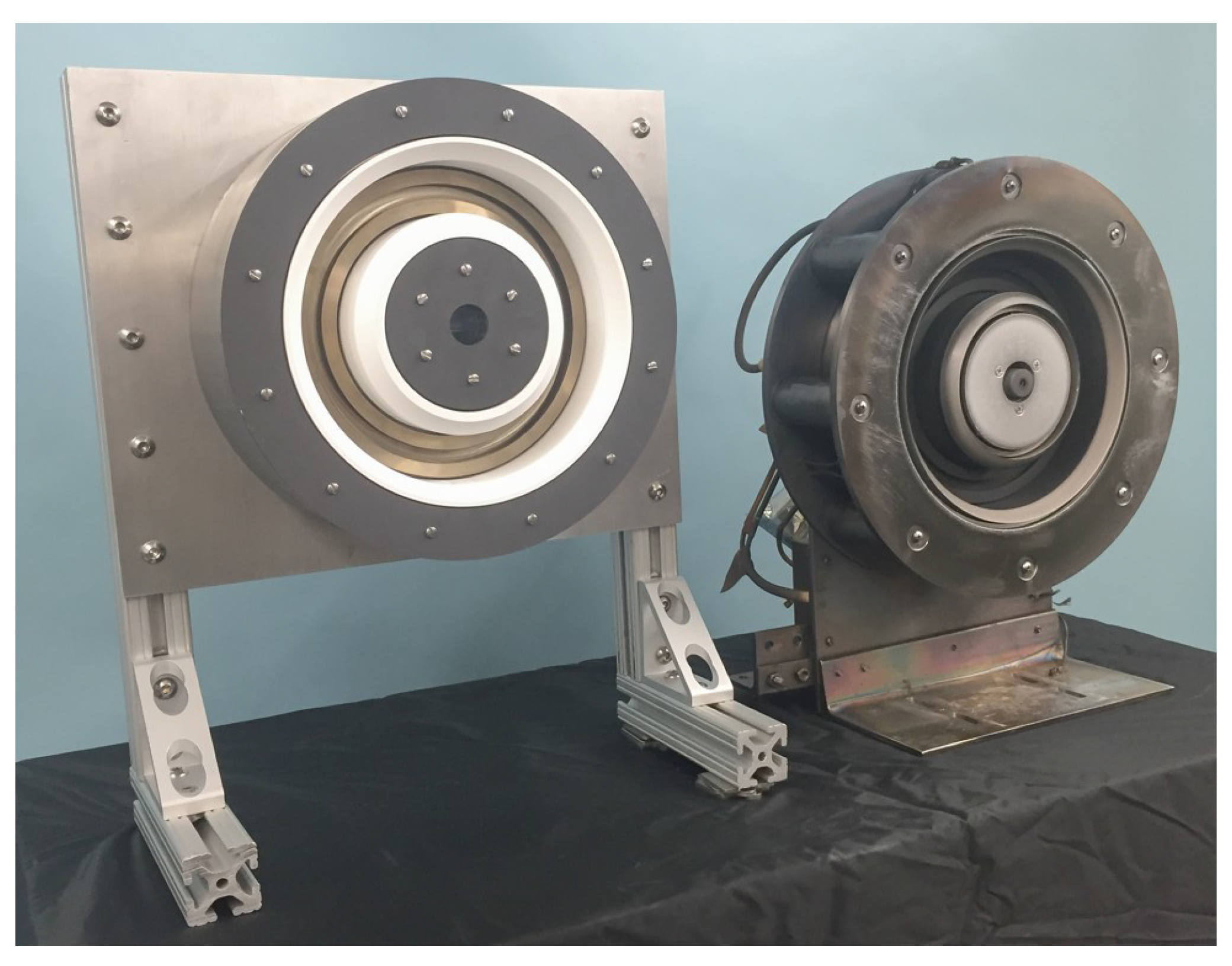
The Hall effect thruster has emerged as one of the most popular EP solutions to achieve relatively high thrust-to-power and efficiency above 1 kW. These devices in this power range are at the top of their s-curve with growing flight heritage, as shown in Figure 8, and are naturally evolved from the low-power Hall thrusters discussed in Section 4.1.1. For example, the Fakel SPT-100, Safran PPS-1350, and Aeroject Rocketdyne XR-5 are all moderate-power Hall thrusters with a low-power lineage. Since the introduction of Hall thrusters to the West in the early 1990s, there have been significant improvements in the efficiency and longevity of this technology. Hofer et al. studied the plasma lens magnetic field topography, proving that Hall thruster anode efficiency can reach nearly 70% with specific impulses exceeding 3000 s [49]. Figure 9 shows laboratory thrusters that resulted from this research.
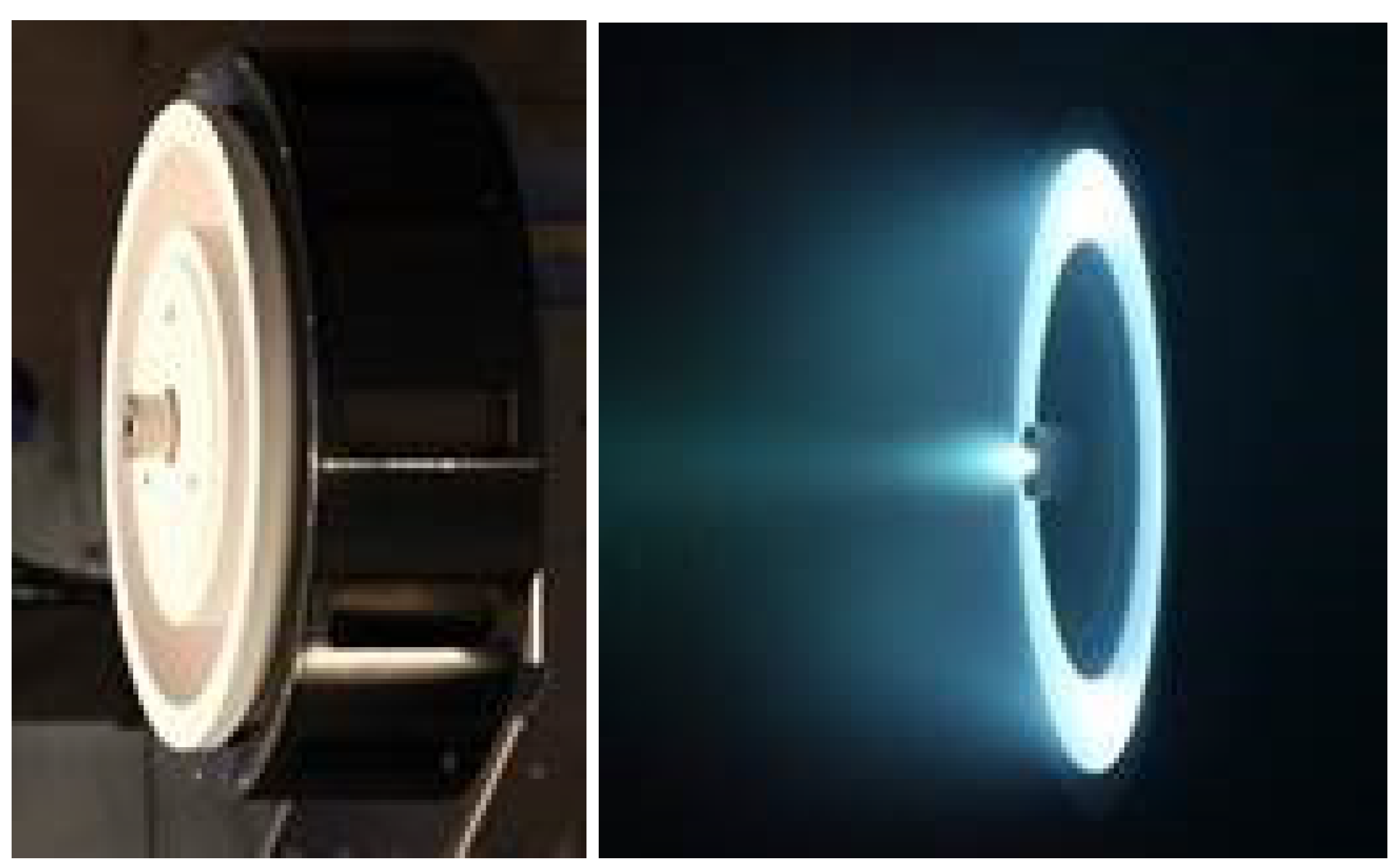
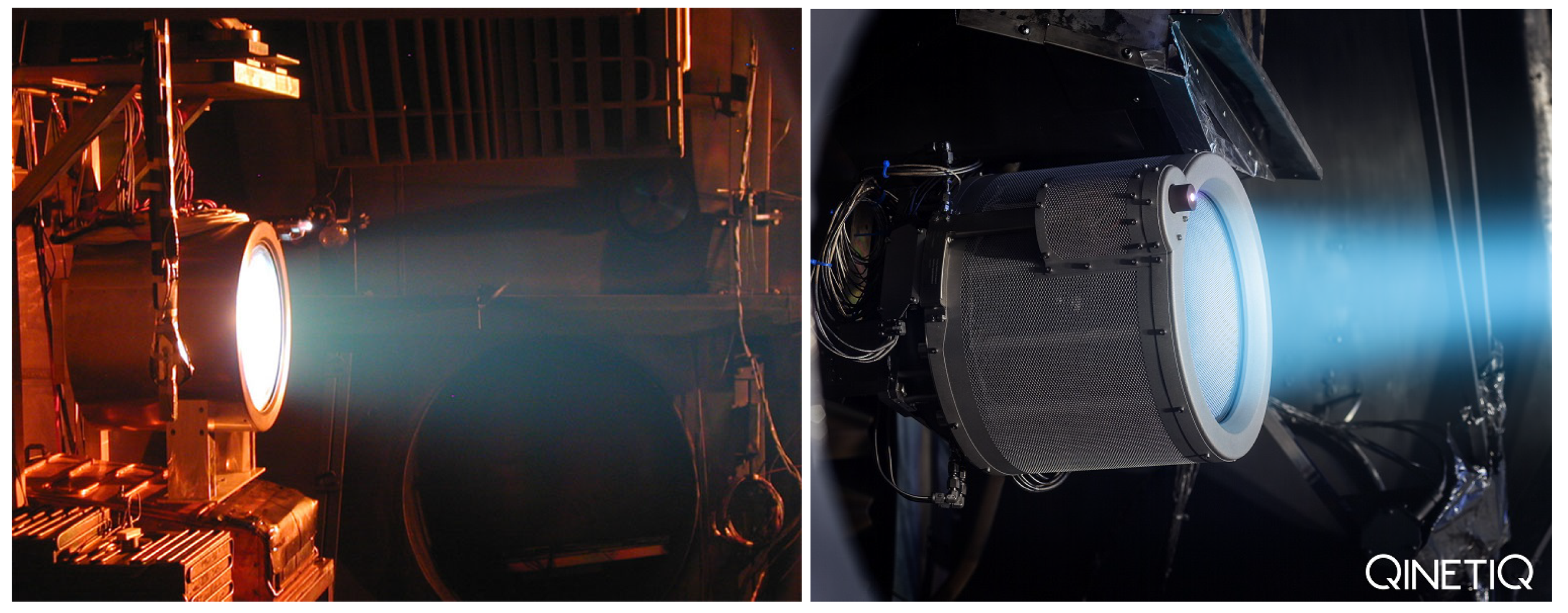
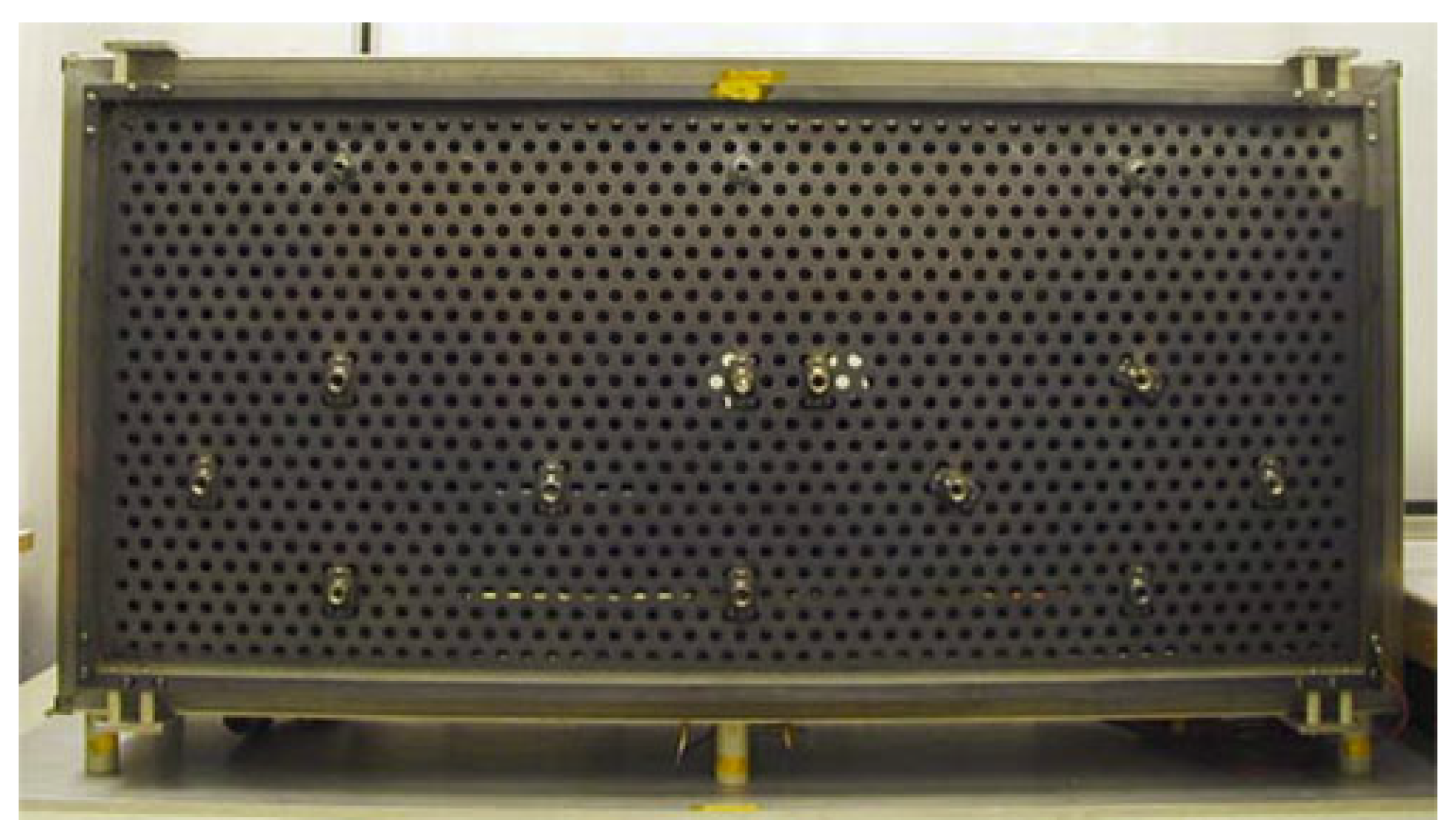
Further, the application of magnetically-shielded topographies has reduced thruster channel erosion by several orders of magnitude, eliminating this historical life-limiting process in Hall thrusters [50]. The power of these devices has steadily increased over the years as well, culminating in the flight of the 5 kW XR-5 [51] and SPT-140 [52], the near-term development of NASA’s Hall Effect Rocket with Magnetic Shielding (HERMeS) 12.5 kW thruster to support cislunar activities [53], the study of 20 kW Hall thrusters at SITAEL (shown in Figure 10) and CNRS in support of ESA goals [54,55], and the ground demonstration of a nested Hall thruster at 100 kW [56] (to be discussed in Section 4.3.1). Nearly one hundred Hall thrusters have flown on satellites in geostationary orbit [57], one has flown in lunar orbit [58], over 400 are flying as part of the incomplete SpaceX Starlink constellation (as of 2020), and soon several low-power articles will be employed in the deep space mission to visit the minor planet 16 Psyche [59].
Despite the growing flight heritage of Hall thrusters, there remain a number of technical challenges related to their operation. For example, it has long been acknowledged that ground testing of in-space propulsion systems may not be entirely representative of flight performance, in large part due to differences in pressure and the presence of conductive and sputterable chamber surfaces. Early work by Randolph et al. identified background pressure and chamber sputtering as having an effect on SPT life testing [60]. Typical operating pressures for electric propulsion testing on the ground are ∼1 μ Torr at best due to finite pumping speed; this pressure is still several orders of magnitude higher than low Earth orbit [61]. Studies of thruster performance as a function of facility pressure have highlighted that indeed many aspects of Hall thruster operation are sensitive to pressure. For example, Diamant et al. showed that thrust decreases with pressure [62], which invites the disappointing possibility that Hall thrusters are less effective in space than on the ground. Similar studies by Walker at the University of Michigan yielded trends of decreasing thrust with pressure for a wide range of discharge voltages [63].
Aside from pressure, the electrical configuration of the thruster during ground tests also constitutes a facility effect. A thruster operated in a vacuum chamber is enclosed in a grounded vessel, such that the thruster plume interacts with the vessel and is influenced by it. For instance, with a grounded chamber and/or beam dump, a nonzero amount of beam current is sunk into the chamber, requiring current to be sourced elsewhere; thus, the shape and material of the chamber walls and how they communicate with the thruster plasma may impact performance. In studies in which conducting plates were placed throughout a vacuum chamber, it was observed that the thruster was sensitive to the bias of these plates, but the overall performance did not change greatly as the cathode was moved closer to them [64]. This indicates that the electrical effect of the vacuum vessel on the thruster exists, but may be subtle.
Another open question in Hall thruster research is the nature of the various instabilities exhibited in these devices. The presence of a wide variety of oscillations in Hall thrusters has been known for decades [65], extensively examined theoretically [66,67,68,69,70], and studied in numerical simulations [71,72,73,74,75]. Despite the fact that many of these instabilities are expected to play a significant role in the fundamental operation of Hall thrusters, most of them are still poorly understood and inconsistently reproduced in simulations.
A final aspect of moderate-power Hall thrusters that still requires research is lifetime qualification for these devices. Lifetime testing in ground facilities is still the primary tool for verifying the long-term performance of a thruster, which is logistically taxing due to stringent testing requirements [60] and ultimately delays the application of new designs. Dankanich et al. echoed this sentiment in [76], opining that the standard 150% lifetime test requirement is impractical and further arguing the following points: standalone tests cannot establish reliability; more ambitious deep space missions increase the qualification demands on thrusters; and time-dependent failure modes may not be captured due to differences between ground and flight throttling profiles.

4.2.2. Gridded Ion Thrusters

Although Hall thrusters are high on their s-curve, as shown in Figure 8, moderate-power gridded ion thrusters are perhaps slightly more mature, having reached their inflection point near the turn of the century. Gridded ion thrusters at 1–20 kW were developed heavily and flown extensively by the U.S. during the Twentieth Century; for example, the Xenon Ion Propulsion System family of GITs developed by (first Hughes and then) Boeing were flown extensively in the 1990s [77]. These devices similarly have been flown in deep space missions like Dawn [78] and (at slightly lower power levels) Hayabusa [79] and, currently, the BepiColombo mission to Mercury [80]. Further, they have undergone extensive wear testing in ground facilities [81,82], which has led to improvements in the understanding of the erosion of these thrusters [83]. Figure 11 shows an example of two state-of-the-art gridded ion thrusters.
The challenges facing GITs at moderate power levels are now largely related to incremental improvements in the testing and implementation of these devices. For instance, facility effects are known to influence GITs as they do Hall thrusters. For example, numerical modeling accompanying life tests of the NASA Evolutionary Xenon Thruster (NEXT) indicated that accelerator grid groove erosion could be reduced by 30% due to redeposition of sputtered beam dump material [85]; this effect, if unaccounted for, could spuriously increase estimates of thruster longevity and therefore pose a significant risk for flight operation. Assessing the lifetime of moderately-powered GITs is another lingering obstacle. Although simulations can effectively reproduce erosion patterns in these devices, the causes of cathode erosion and failure are manifold and still under study [86,87], and the presence of long-duration failure mechanisms are difficult to explore without strenuous ground testing.
Alternatives to gridded ion thrusters at moderate power levels that overcome the fundamental space-charge-limited operation of this technology are also being explored. For example, the High-Efficiency Multi-stage Plasma (HEMP) thruster is a cusped-field thruster in development by Thales Electron Devices GmbH since 1996 [88] and has demonstrated over 6600 h of operation in life tests [89]. This technology, although firmly not a type of GIT, is generally considered to occupy a similar performance space. There is also the exploration of extending this concept to low power, where the magnetic shielding of the discharge chamber walls greatly reduces heat loss [90].

4.2.3. Pulsed Inductive Thrusters

Pulsed inductive thrusters in the 1–20 kW range have been developed over the past few decades, although the pace of progress has lagged behind other technologies, placing PITs fairly low on their s-curve in Figure 8. In particular, planar and conical theta-pinch (CTP) pulsed inductive thrusters have been studied extensively starting with the groundbreaking work by Dailey and Lovberg [91,92] in the early 1980s. This research has culminated in the development and testing of the PIT MkV [93], which can be operated with 8 kJ pulses, and the low-energy Faraday Accelerator with Radio-frequency Assisted Discharge (FARAD) [94], demonstrating 50% thrust efficiency. Most recently, there has also been the operation of several CTPs and inductive pulsed plasma thrusters (IPPTs) and the characterization of the efficiency and impulse bit of some of these devices [95]. During this time, there have also been many numerical and theoretical investigations of these devices.
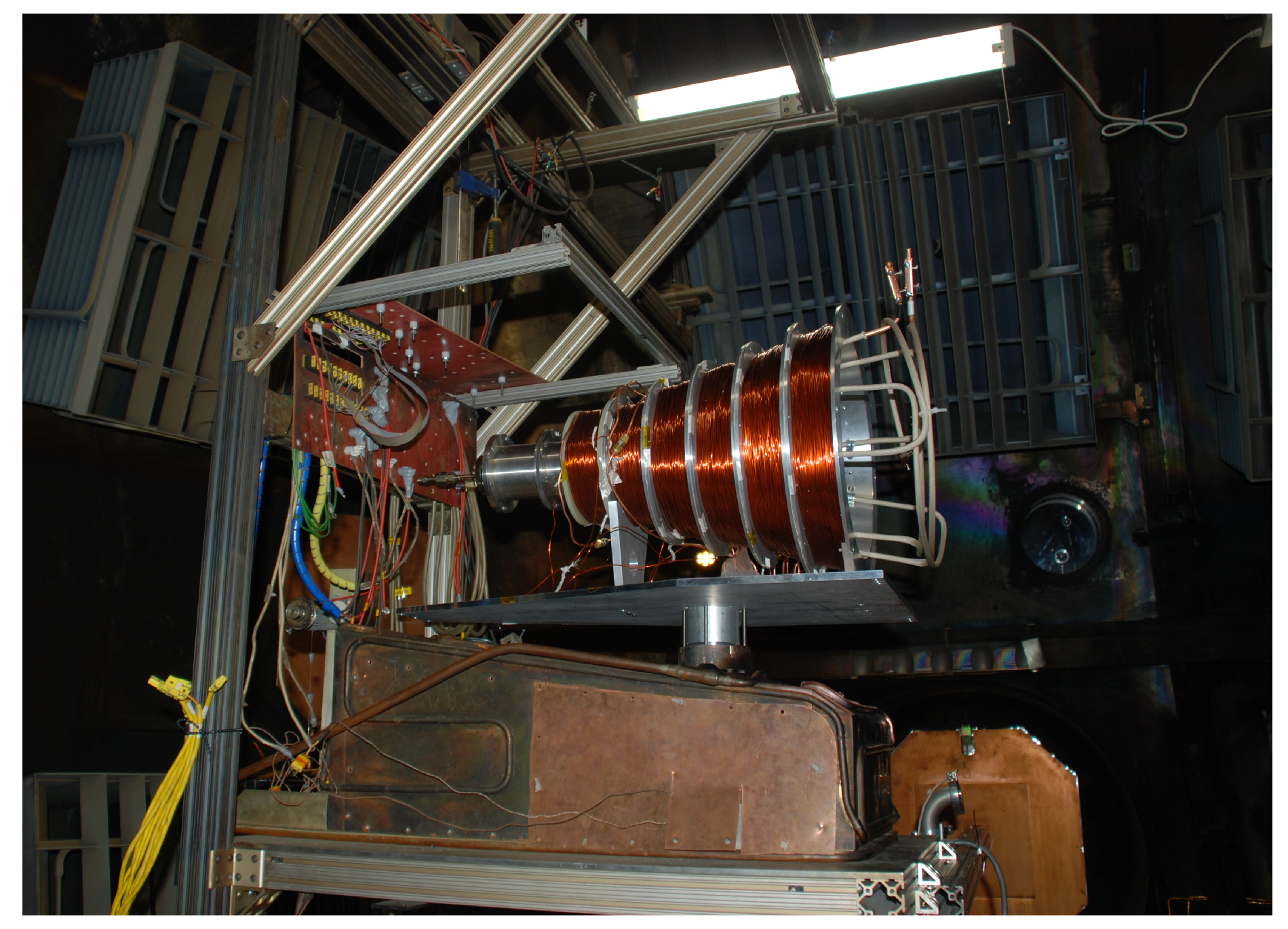
Likewise, there have been significant strides in the development of field-reversed configuration devices, which inductively generate and magnetically eject isolated plasmoids in a pulsed fashion. Originating in the fusion community [96], this technology is now applied on smaller scales for propulsion purposes. Although the production and acceleration of plasmoids with these devices has been confirmed [97,98,99], the understanding of their practical performance and numerical simulation remain limited [100,101]. Figure 12 shows a related example of an experimental rotating magnetic field thruster currently under test at the University of Michigan.
Perhaps the largest challenge in the development of these thrusters is that they are expected to perform well at high power, perhaps far in excess of 20 kW, and so the construction and testing of prototype PITs requires significant investment in niche power electronics [102] and testing facilities. As a result, the research to date at almost exclusively <20 kW has made it difficult to fully explore the theoretical operation of these devices and assess their practicality.

4.3. High-Power Thrusters

The low thrust produced by modern electric propulsion devices has created a large divide between the applications for which they are suited and those where chemical propulsion is more fitting. For example, crewed missions prioritize short travel times, and thus, the large thrust produced by chemical systems is needed even at the expense of payload mass. However, with more power, EP systems may produce enough thrust to break into this niche, while retaining the propellant efficiency characteristic of this class of propulsion. As a result, there is continuing research into scaling EP devices to higher power and exploring new concepts that may excel at ≫20 kW. We depict the s-curves for some of these devices in Figure 13.
Some constraints in this direction of EP research have already been established by mass modeling and mission analysis. Hofer and Randolph developed a mass and cost model that indicated clustered Hall thrusters in the (individual) 20–100 kW range would be capable of supporting missions from 20 kW to 1 MW [103]. Dankanich et al. examined Mars mission profiles in terms of the system mass-to-power ratio, α ; they found that an α of 1 kg/kW can allow for 40-day trips to Mars using variable- I s p high-power electric propulsion [104]. With these studies in mind, it is clear that high-power EP development should focus on power levels 20–100 kW and with α 1 kg/kW.

4.3.1. High-Power Hall Effect Thrusters

Figure 13 indicates that Hall thrusters at high power, although moderately mature, are advancing relatively slowly compared to their moderate-power equivalents. In the first decade of the Twenty-first Century, it was quickly realized that physically scaling up moderate-power Hall thrusters was impractical; for example, designs were drawn for a “NASA-1000M” thruster that would be an unprecedented 1 m in diameter and operate at 150 kW, yet this device was never constructed [105]. Since then, several ideas have been explored to scale Hall thrusters to higher power while keeping them competitive in terms of footprint and mass. For example, clustering of Hall thrusters has been studied at length, including the performance of clusters sharing a cathode [106] and the interaction of the plumes of clustered thrusters [107]. In fact, the current Lunar Orbital Platform-Gateway concept Power and Propulsion Element involves a cluster of 13.3 kW Hall thrusters to form a 50 kW system with a α of roughly 0.3 kW/kg [108].
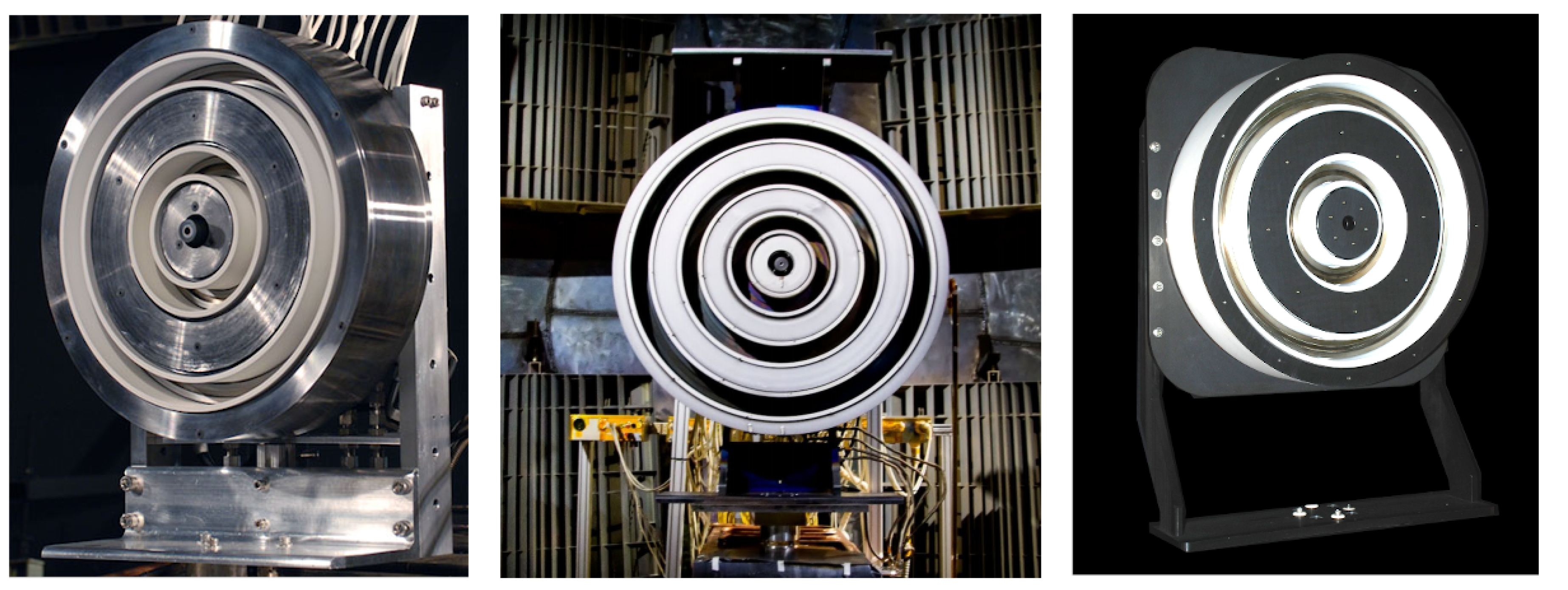
Another approach has been the nesting of Hall thrusters, studied at the University of Michigan and culminating in the two-channel X2 [109], three-channel X3 [56], and the magnetically-shielded two-channel N30 [110] at power levels of 10 kW, 100 kW, and 33 kW, respectively. Figure 14 shows these three thrusters. By sharing a magnetic circuit and capitalizing on the traditional Hall thruster annular shape, these thrusters have a reduced mass and footprint compared with equivalent clustered and monolithic systems [111].
Despite the impressive headway made in researching high-power Hall thrusters, many challenges have emerged that have impeded their development. Foremost, ground testing facilities are largely incapable of handling the high gas throughput of these devices, bringing into question the role of facility effects as described in Section 4.2.1. For example, the X3 was only recently tested to a record-setting 100 kW [56], but these experiments were short duration and had to be conducted in Glenn Research Center’s Vacuum Facility 5, a chamber far more capable than those to which most researchers have access. And yet this facility was barely able to maintain a background pressure during these tests within the standard of Randolph et al. [60]—assuming this standard is even still applicable to such large devices. Additionally, such tests become increasingly uneconomical for higher power thrusters due to the cost of the most common propellant, xenon; for this reason, more plentiful gases like krypton are being explored.
Further, there remain many outstanding physical questions regarding nested Hall thrusters. For example, the study of hot interaction between channels has only been preliminary [112]. Although there have been recent strides in optimizing magnetic field topography for different multi-channel operating modes, this too is still an area ripe for investigation.

4.3.2. High-Power Gridded Ion Thrusters

Unlike many forms of electric propulsion, high-power gridded ion thrusters were explored several decades ago, including a 130 kW mercury thruster [113], and thus, they have long since climbed their s-curve in Figure 13. Although many high-power GITs were constructed and tested, the complexity and power requirements of these designs far outstripped what was (and arguably still is) practical for flight. Thus, GIT research was refocused toward more moderate power levels, leading to the Deep Space 1 mission flying a 2.3 kW NASA Solar Technology Readiness (NSTAR) thruster in 1998 [114].
Over the intervening decades, the advancements in high-power GITs (>20 kW) have been limited. The state-of-the-art NEXT thruster, for example, is designed for <7 kW [115]. Practical devices from the few modern forays into >20 kW GITs, such as the High Power Electric Propulsion (HiPEP) system shown in Figure 15 targeted for a Jupiter mission [116], were not advanced beyond laboratory models. There are several reasons for this relatively slow development of higher power GITs. First, as mentioned in Section 4.1.2, GIT beam current is ultimately space-charge-limited, and thus, high-power thrusters must be physically larger and are therefore more challenging to test and fly. For example, the 130 kW mercury GIT tested at Glenn Research Center in 1967 was a cumbersome 1.5 m in diameter, much larger than present day flight EP systems. Second, the successful ground testing of such large GITs in the past was in part accomplished by using easily pumped propellants like mercury and cesium; however, such toxic and reactive fuels are mostly avoided in modern EP systems for both concerns of health and spacecraft interaction. As with other high-power EP technologies, then, the high gas throughput of these GITs easily overwhelms most ground vacuum facilities.

4.3.3. Magnetoplasmadynamic Thrusters

Similar to high-power gridded ion thrusters, magnetoplasmadynamic (MPD) thrusters are an existing electric propulsion technology that have long since been designed and tested to high power in ground facilities and have even been fired in orbit. In fact, several devices were pulsed at up to 1 MW three decades ago [117,118], and a 1 kW class unit flew on the Japanese Space Flyer Unit spacecraft not long after [119]. These devices establish an arc discharge between concentric electrodes; the Lorentz force then accelerates the arc plasma along the electrodes and out of the device. The 100 kW SX3 applied field MPD developed by the Institute of Space Systems (IRS) is shown as an example in Figure 16. This technology has been studied for decades, e.g., [120,121,122], with gradual improvements in efficiency—in excess of 60% [123] and I s p close to 7000 s [124]—and various propellants. For this reason, they have traveled slightly up their s-curve in Figure 13 and may inflect in the near future, but there are formidable remaining challenges for this technology.
The main challenge for MPDs is simply that their performance is poor at power levels <100 kW. By the same token, any high-performance designs are currently impractical due to the lack of appropriate in-space power systems: high-current, high-power supplies that allow for high-frequency operation. Research into applied field MPDs has indicated that high thrust efficiency can still be achieved at lower power levels, but at the cost of higher mass-to-power [126]. Additionally, the limited lifetime of MPDs may make them less competitive against other forms of electric propulsion, especially for most laboratory designs of middling efficiency that are currently tested in the 20–100 kW range. Recent advances at the University of Stuttgart suggest that different operating modes and the use of a LaB 6 cathode and regulated voltage supply may simplify the power processing electronics and extend the lifetime of these devices [123].

4.3.4. Large-Scale Electrospray Arrays

Massively scaled electrospray arrays could potentially usurp all other forms of electric propulsion in terms of thrust-to-power in the future. As we show in Figure 13, this technology is still very low on its s-curve, but we expect rapid maturation in the near future. With high efficiencies (>70%), high specific impulse (>1000 s), and high thrust-per-mass, but low thrust-per-emitter (∼1 μ N), large-scale electrospray arrays could match the thrust of other technologies, but with much greater efficiency [127]. As discussed in Section 4.1.3, present scaling of electrospray thrusters is challenged by life-limiting physical effects and engineering constraints. If these issues can be solved, the thrust of an electrospray array would only be limited by the emitter density—the upper limits of which are still unclear—and the available surface area of a spacecraft.

4.3.5. Pulsed Inductive Thrusters

High-power pulsed inductive thrusters are only sparsely studied, and thus, their maturity in Figure 13 is still quite low. As discussed with moderate-power PITs in Section 4.2.3, there is yet incomplete understanding of the physical operation of these thrusters, and thus, developing them for high power is challenging and often unproductive. Moreover, the sophisticated power electronics needed to operate these devices at high power present a major engineering challenge; for instance, modern PIT designs as described in [102] involve switching components handling ∼10 kA over the span of ∼10 ns. Scaling these components for higher power operation may therefore soon be stonewalled by the material and manufacturing limitations of the thruster’s power electronics.

4.3.6. Magnetic Nozzles

Although magnetic nozzles are now being considered as an economical EP solution for small satellites (see Section 4.1.4), these devices can also be employed for high-power propulsion. Interestingly, we believe high-power magnetic nozzles are nearly as mature as their low-power equivalents, but the former’s s-curve is much broader. The most prominent example of a high-power nozzled EP thruster is the Variable Specific Impulse Magnetoplasma Rocket (VASIMR), an ion cyclotron resonance thruster outfitted with superconducting magnets to produce an exceedingly strong magnetic nozzle [128]. This device has been researched in earnest since the 1990s. Most recently, long-duration testing of VASIMR has led to the accumulation of roughly 100 h of operation at over 100 kW [129].
High-power electron cyclotron resonance magnetic nozzle propulsion was also studied by Sercel both theoretically and experimentally in the early 1990s [130]. For a laboratory argon-fed accelerator with microwave power between 0.4 and 7 kW, he found experimental power efficiencies to be much poorer than anticipated, but the overall nozzle efficiency was still approximately 24% and could be as high as 90% in theory. Further, it was speculated in this work that using different propellants like deuterium could significantly reduce some loss mechanisms.
These examples of past high-power magnetic nozzle studies highlight some of the current challenges to the advancement of this technology. Specifically, since magnetic nozzles require a strong magnetic field to guide electrons out of the device, high-power nozzled thrusters with dense plasmas will require magnetic fields of unprecedented intensity. In the case of VASIMR, considerable infrastructure is needed to produce the ∼2 T field strengths required for this device [131], and the other power processing requirements are equally challenging [132]. Moreover, the efficiency of magnetic nozzles at <1 kW is notoriously poor, as mentioned in Section 4.1.4 based on [36], and although VASIMR may reach efficiencies in excess of 60% [129], it is not clear if this success will hold for for devices in the gaping 1–100 kW span that is largely unexplored. For this reason, the investment of developing a high-power nozzled thruster is unfavorable for most research institutions.

4.3.7. Nuclear Thermal Propulsion

As shown by their absence in Figure 13, resistojets and arcjets are generally not considered for scaling to high power. However, a natural extension of these technologies is nuclear propulsion, where a sustained fission reaction is used to heat a propellant, producing thrust once expanded out of a nozzle. As will be discussed in Section 5.4, in-space reactor technology is still in its infancy, so naturally, no form of nuclear propulsion has been flown. Interestingly, ground tests of one example of this technology, the Nuclear Engine for Rocket Vehicle Application (NERVA), were performed in the 1960s [133]. The main obstacles for the development and flight of nuclear thermal thrusters—aligned with those for in-space reactors—include effective thermal management, launch safety, and efficient heat transfer.

4.4. Summary of Shared Challenges for Electric Propulsion Technology Development

In the preceding sections of this article, we discussed in detail the challenges posed to various EP technologies that fall into the <1 kW, 1–20 kW, and >20 kW ranges. In retrospect, many of these challenges are shared within each power level. We now summarize these obstacles for mature (high on the s-curve) and immature (low on the s-curve) electric propulsion systems. In Section 5, we discuss strategies for overcoming these roadblocks.

4.4.1. Technologies High on The S-Curve

Most mature EP thrusters are those in the moderate power range, 1–20 kW, as this has been the primary power level researched in the past several decades. In general, most of these technologies are limited by incomplete understanding of subtle physical processes and the mounting inadequacy of ground test facilities for long-lived designs. For example, although many flight Hall thrusters are operated >1 kW, poor understanding of electron transport and instabilities in these thrusters prevent the development of predictive models that might enable the more rapid and intelligent design of 10–20 kW test articles. And as a result, assessing the long-term performance of moderate-powered Hall thrusters must mostly be done in ground test facilities. Compounding the logistical strain such tests impose, the effect of the facility on the thruster performance casts some level of doubt on the extensibility of ground test results to on-orbit behavior, as discussed briefly in Section 4.2.1. We summarize these challenges as follows:
  • Understanding anomalous processes and instabilities to allow for self-consistent modeling;
  • Modeling or mitigating facility effects to allow for more meaningful ground testing;
  • Finding alternatives to long-duration testing to characterize reliability, long-term performance, and time-dependent failure mechanisms.
A solution to the challenges faced by mature EP technologies, then, is improved modeling and ground test facilities. The former will help close the final gaps in the understanding of mature thrusters, and the latter will allow for more thorough and definitive testing of these devices. Specifically, we make the following recommendations for addressing the challenges to the “high s-curve” technologies:
  • Requirements for a test environment to adequately represent space-like conditions must be formulated accounting for the unique characteristics of modern mature EP technologies;
  • Formulate strategies to make ground facilities more flight-like;
  • Improved predictive and validated models for qualification efforts to address problems related to facility interactions and stability.

4.4.2. Technologies Lower on The S-Curve

While in theory many of the technologies shown in Figure 3, Figure 8, and Figure 13 could meet the expanding need of the space industry, nearly all of them remain low on their s-curve at some power level and, thus, not ready for flight. There are several shared challenges that would need to be addressed to raise the maturity of these technologies. We summarize these as follows:
  • Scaling to low power incurs increasing ionization cost;
  • Optimal performance is anticipated above practical or economical power levels for laboratory development (typically ≫100 kW);
  • Incomplete theoretical understanding of performance or lifetime.
Following the historical precedent set by Hall thrusters and gridded ion thrusters, the development cycle to bring these systems into flight-readiness could take decades. This is assuming that none of the known technical challenges for these systems prove to be logistically insurmountable in the foreseeable future. For example, it is still an open question if there are fundamental limitations to the packing density of electrosprays or for the theoretical upper limit of performance for PITs. Additionally, there must be sufficient “pull” from mission planners to maintain research interest in these technologies; if no missions are suited to massively-scaled electrospray arrays, the development of this technology will stagnate, shallowing the s-curve. With that said, the growing and immediate need for low- or high-power propulsion solutions means that there may not be time to follow more traditional development cycles. There is a vested interest, then, in being able to increase the slope of the s-curve for these technologies. To resolve the issues slowing the development of “low s-curve” technologies, we make the broad recommendations below, and in the following section we discuss specific strategies to this end.
  • Establish the theoretical bounds in performance and identify any fundamental limitations;
  • Develop techniques for optimization that more rapidly allow the theoretical performance to be realized experimentally.

5. Strategies for Addressing Technical Challenges for Electric Propulsion Development

We now review possible strategies for overcoming the challenges faced by many electric propulsion technologies. Drawing from the lists presented in Section 4.4, we discuss approaches to several specific problems: facility effects, lifetime qualification, and predictive modeling. We additionally discuss more abstractly the lowering of system specific mass and improving power processing systems.

5.1. Facility Effects

From an operational perspective, there is a pressing need to try to account for the influence of the facility on a thruster’s operation. As reviewed in Section 4.2.1, due to limitations in facility pumping speeds, it is not possible to recreate pressures consistent with a flight environment. Instead, it is becoming an increasingly common practice to try to account for this facility effect by performing parametric studies: the facility pressure is varied above the minimum operating pressure while key aspects of thruster behavior (performance and power) are monitored. A function is then fit to these data and used to extrapolate to a space-like environment (i.e., zero pressure). Studies like this have also yielded certain practical solutions to facility pressure effects, such as using a centrally-mounted cathode [134] or operating at an elevated cathode flow fraction to “drown out” background gas [110] in Hall thrusters. A major difficulty in performing these types of studies is that only a few orders of magnitude of pressure can be spanned in ground testing. That is, work by Randolph et al. suggested 50 μ Torr as an upper limit of pressure for Hall thruster testing based on the onset of background pressure-induced oscillations [60], which means most ground studies of pressure effects are limited to only two orders of magnitude, ∼1 to ∼10 μ Torr. In contrast, there are at least four orders of magnitude of pressure difference (∼1 nTorr to ∼10 μ Torr) between ground testing and in-space operation, so there is no guarantee that ground pressure studies are extensible to flight operation.
An equally important limitation of the parametric approach is that it is not clear what type of model should be used to fit the resulting data. Different models ranging from simple linear extrapolations to transcendental functions have been applied in the past [110,134,135,136,137,138,139,140]. In each case, however, these models are not rooted in the underlying physical processes, but are simply empirical fits. For example, the decrease in thrust with pressure may be linear over the experimental range that can be tested, but there is no theoretical basis to expect this trend should hold as pressures approach zero. Faced with this limitation, there is a pressing need to identify physics-based, experimentally-validated models for the response of the thruster to facility pressure. This remains a critical area of research, as evinced by [141,142,143,144].
In an effort to overcome these challenges, one promising strategy to understanding the pressure effect on thrusters is to adopt a probabilistic approach. This builds on the current methods for determining facility effects that are based on extrapolating parametric studies of pressure to space-like conditions. In this case, however, simplified physics-based scaling laws are combined with rigorous model inference to make predictions within well-defined uncertainty for on-orbit behavior. For example, Bayesian analysis of thruster performance metrics as a function of pressure can yield rigorous quantifications of performance uncertainty when extrapolating to lower pressures [143]. Alternatively, high-fidelity models can be tuned to experimental data at non-zero pressure and then used to estimate performance at zero pressure without explicitly assuming any functional forms for pressure dependence [144].
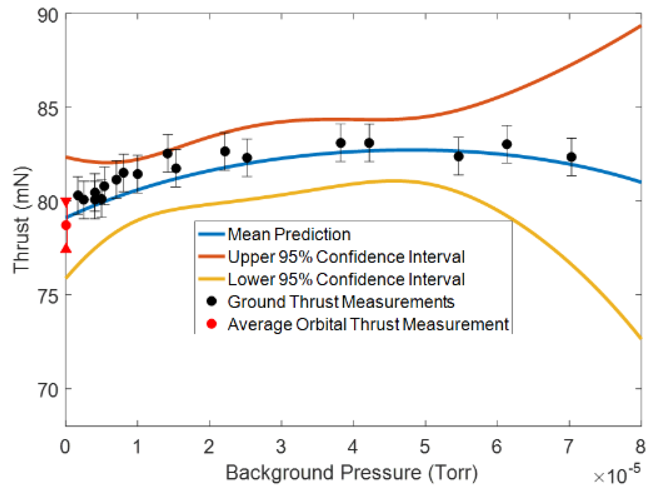
Further, these sophisticated statistical and numerical analysis techniques can be used synergistically to understand the underlying physics of facility interaction. As an example, given a set of thrust data taken in a ground facility and an assumed functional form for thrust, a Bayesian analysis can provide physical insight into estimates of thrust and its uncertainty at space-like pressures. This sort of approach can be used to identify the important thruster parameters that are affected by pressure and thereby assist the theoretical and numerical modeling of pressure effects. The initial steps in this process have been attempted by Byrne and Jorns to successfully replicate in-space thrust values based on statistical data, as shown in Figure 17, while also giving insight into the major parameters controlling thrust [143].
Ultimately, as we expand to higher power, the challenge of facility effects will become even more problematic. With higher gas throughput, it will be more difficult to sustain acceptably low pressures, and even the definition of “acceptably low” may come into question. In addition, higher power systems may introduce new physical effects or modify the dominance of certain physical processes in thrusters, which may alter the influence of the facility on performance. It is of great importance, then, to develop techniques to access and understand the physical processes controlling the interaction between the facility and the thruster.

5.2. Lifetime Extension and Qualification

Another objective that addresses many of the technical challenges of EP systems is to increase thruster longevity and improve qualification techniques. As mentioned in Section 4.2.1 in the context of Hall thrusters, current qualification standards are impractical for long-lived EP systems. Qualification challenges cannot entirely be mitigated by better ground test facilities, but instead, self-consistent numerical modeling may fill this role. Higher fidelity models currently complement ground tests in that they are used to verify performance and lifetime measurements. However, using these models to supplement ground tests could allow long-term thruster performance and failure to be predicted with high-fidelity codes based on short-duration experiments. For example, models of gridded ion thruster failure modes have been compared against experimental data and used practically in conjunction with them to inform future test conditions [145].
In terms of increasing thruster lifetime, the exploration of electrodeless technologies are a natural research direction for circumventing life-limiting failure mechanisms associated with plasma-wetted systems. However, even in these latter devices, new designs are being explored to extend operating lifetimes. For example, the application of magnetic shielding design principles to Hall thrusters has increased the longevity of these devices and, with continuing research into other erosion mechanisms in these thrusters, may prove a key asset in the future of high-power electric propulsion. The 12.5 kW HERMeS thruster, for example, is designed for 10,000 h of operation, and preliminary ground testing has indicated that it can indeed meet this goal [53]. A thruster like that—with sufficient longevity and power—is in a position to serve as the workhorse of high-power electric propulsion for the near future. Additionally, continuing research into heaterless cathodes is simultaneously promising to diminish lifetime risks due to traditional cathode erosion [18].

5.3. Predictive Models for Incompletely-Understood Systems

Validated and predictive numerical models could be a key enabler for addressing challenges related to both mature and immature concepts. As an example, for technologies higher on the s-curve where the relevant physical processes are well understood, numerical models are critical for performing lifetime assessments. For technologies lower on the s-curve, numerical models can help guide the rapid advancement of the technology by exploring underlying physical operation to a level of detail unattainable in laboratory experiments. With that said, many of the technologies both higher and lower on the s-curve have aspects of their operation that remain poorly understand. As discussed in the preceding sections, a few notable examples include electron transport in Hall thrusters; many aspects of the operation of electrosprays, such as the onset of failure modes and instability; and the problem of detachment in magnetic nozzles. The lack of understanding of these processes has precluded the development of predictive models.
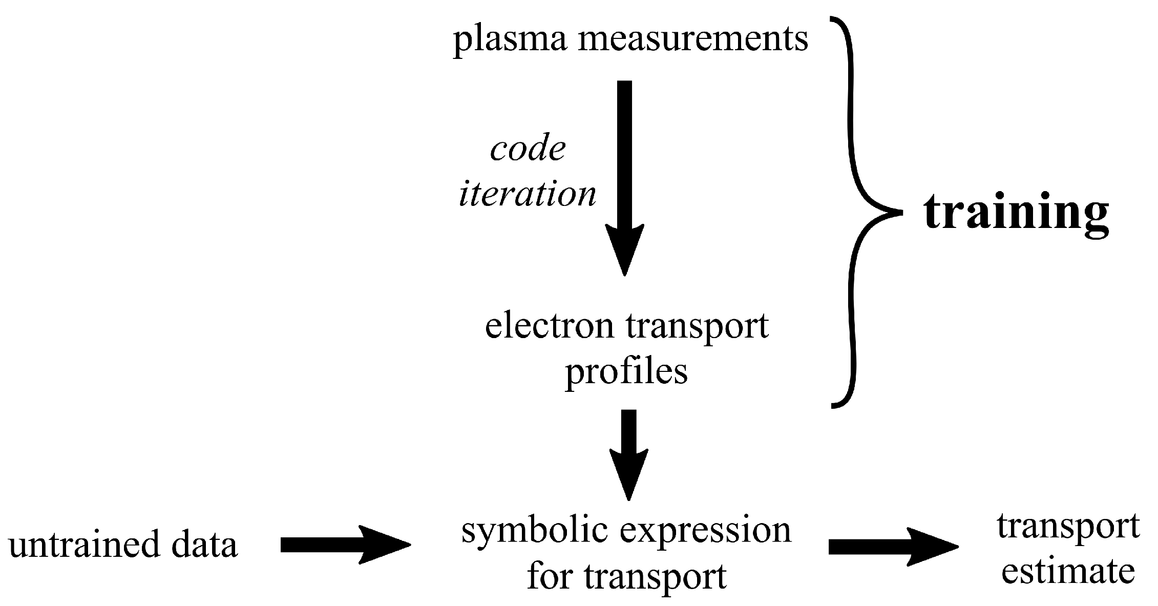
Ideally, future directions in the field of electric propulsion will include dedicated and detailed physics-based studies to produce predictive models that will help mature modern systems. However, this need should be balanced against the fact that some incompletely-understood physical processes in EP devices have been studied for several decades and still remain unresolved. This poses a practical challenge for leveraging numerical tools to address the outstanding and pressing open questions for technology development. As an alternative method to more rapidly advance EP technologies, one emerging strategy is to leverage data-driven methods to develop improved predictive models. As demonstrated in Figure 18, a machine learning regression algorithm may be used to derive functional forms for poorly-understood phenomena like electron transport in Hall thrusters based on available sets of training data. This helps “fill in” pieces of the missing physics, which assists in overcoming some of the hurdles that have prevented the development of self-consistent predictive models to date.
A similar direction has recently been taken with electrospray research, using data-driven techniques to understand the lifetime and failure modes of large-scale arrays in the absence of predictive simulations [33]. These techniques can also be used to optimize existing thruster designs. Figure 19 shows an example of a two-frequency optimization experiment at the University of Michigan from [146], in which the floating potential in the plume of an ECR thruster is maximized through data-driven optimization of applied microwave frequencies.
Despite the incredible promise of data-driven analysis to close gaps in the modern understanding of electric propulsion systems, there are several caveats that must be acknowledged. First, because their results are not based on first principles, data-driven analyses may miss important physics that cannot be distinguished from the training data. Similarly, it is difficult to determine whether a learned expression is applicable outside of the training dataset. For example, a description of electron transport in Hall thrusters may be successfully formulated from machine learning with training data of moderate-power devices, but there is no guarantee that this description is extensible to low- or high-power designs.

5.4. Power and Propellant Improvements

Another priority in advancing electric propulsion technology is improving the physical and electrical properties of these systems to minimize the mass-to-power ratio α and maximize available discharge power. For the former, improvements are mainly by way of more sophisticated and efficient power processing technology. For example, as mentioned in Section 4.1.4, research into nozzled ECR thrusters has accelerated due to the prevalence of compact, light, and inexpensive microwave electronics. Aside from the power processing systems themselves, more direct methods of power conditioning are currently being researched and could play a key role in enabling high-power EP. For example, so-called “direct drive” architectures are being considered in which a propulsion system is designed to operate at the solar panel array voltage. For instance, Snyder et al. operated a 6 kW Hall thruster directly from a solar panel array with only minimal filtering electronics involved [147], demonstrating that many of the power processing systems conventionally paired with flight Hall thrusters may be eschewed for lower α without degrading performance.
Another practical improvement could be in exploring and utilizing advanced or novel propellants. Many higher power EP systems use noble gases like xenon as the propellant, which are expensive, relatively difficult to pump in ground facilities, and cannot readily be stored in solid form onboard a spacecraft. However, other propellants have been investigated that address some of these difficulties, including lithium [148], bismuth [149], iodine [150], and cesium and mercury [151]. Further, electrodeless technologies like PITs are propellant agnostic, which is a significant practical advantage for advancing the state of electric propulsion technology.
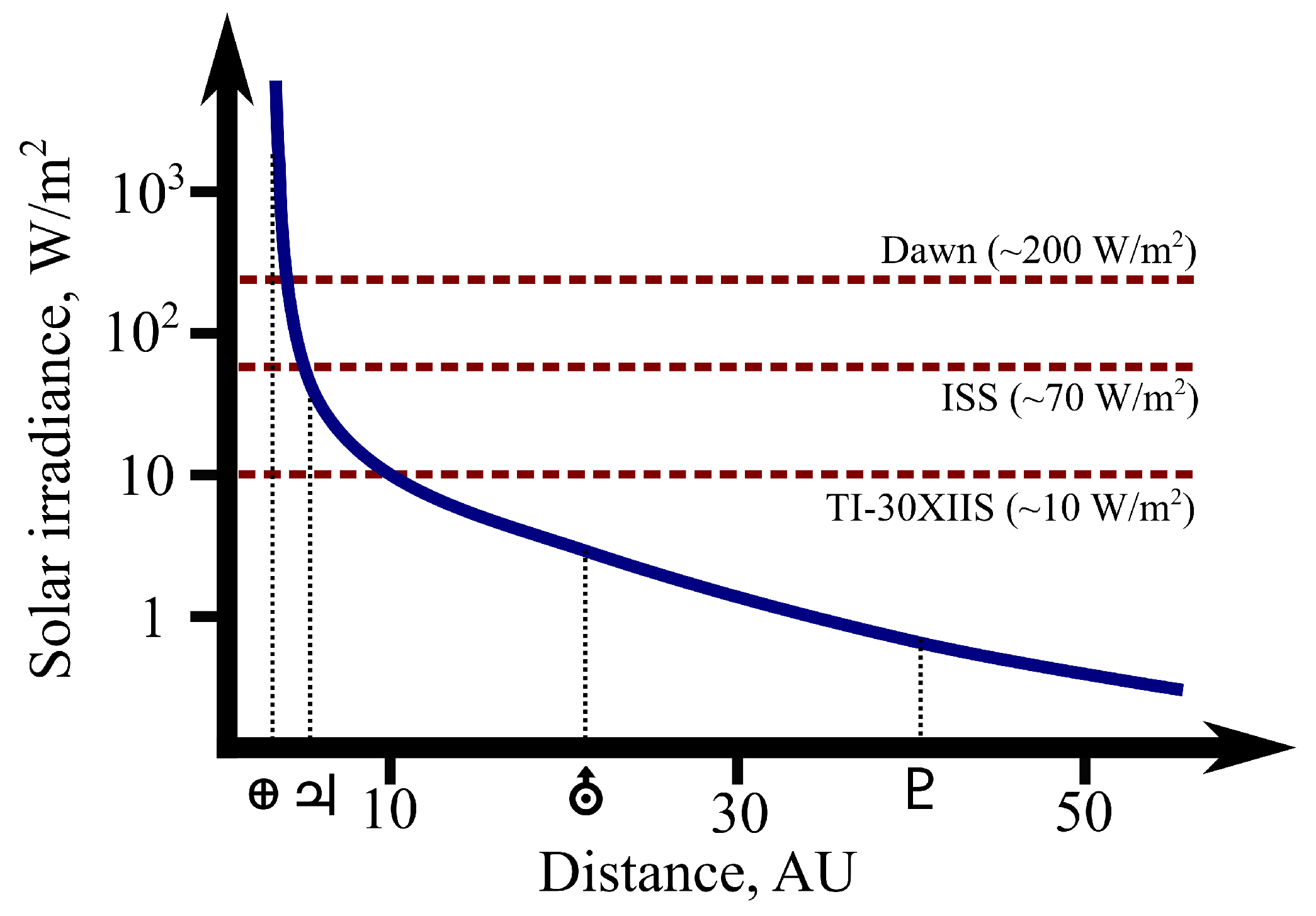
One major factor in guiding the direction of future electric propulsion is the available power source. Currently, all EP systems are “solar electric propulsion” (SEP)—meaning they are powered with solar panels—but with the maturation of in-space fission reactors, for example NASA’s Kilopower project [152], the bottlenecks associated with SEP may disappear. In particular, nuclear electric propulsion (NEP) may enable outer Solar System or extra-Solar missions where traditional solar power is scarce. Figure 20 demonstrates the breadth of applications for NEP in showing that available solar power in the outer Solar System declines orders of magnitude below the capabilities of modern solar panels. Conversely, advances in solar power technology may direct greater attention to SEP, which naturally may emphasize inner Solar System or manned missions that require high thrust. In all likelihood, both roads may be traversed to some extent, where the mileage will be decided by technological developments yet to happen.

6. Summary

In this article, we reviewed the major acceleration schemes employed in electric propulsion, the nature of EP development cycles, open questions related to EP technologies, and potential future strategies to address technical hurdles. For more mature EP devices, we identified the major roadblocks as being the understanding of anomalous process, facility effects, and device lifetime and long-duration testing. For immature EP devices, we saw these challenges as scaling to different power levels, identifying optimal performance conditions, and incomplete understanding of basic performance and lifetime. With the aid of numerical and experimental facility effect investigations, data-driven techniques, and new power sources/processing systems, many of these problems may be overcome.
In general, the field of electric propulsion has evolved significantly over the last century of theory and development. From the musings of Robert Goddard [154] to its successful application outside Earth orbit [58,78,79,155], electric propulsion technology has matured at an unprecedented rate. In particular, the last few decades of EP research and development have yielded inestimable advancements of the field. Based on these trends and the diversity of EP technologies that are being studied, we are optimistic that these advancements will continue into the near and far future.

Author Contributions

The manuscript was written by E.D. with significant contributions and editing by B.J., and supervision by A.G. All authors have read and agreed to the published version of the manuscript.

Funding

This research received no external funding.

Acknowledgments

The authors would like to acknowledge the entirety of the Plasmadynamics and Electric Propulsion Laboratory at the University of Michigan for their contribution of figures to this manuscript. We additionally thank Antonio Gurciullo of Exotrail, Ryan Conversano of JPL, the Wirz research group at UCLA, Atonio Piragino of SITAEL, Rhodri Lewis of QinetiQ, and Georg Herdrich of IRS for permission to reproduce figures.

Conflicts of Interest

The authors declare no conflict of interest.

References

  1. Rogers, E.M. Diffusion of Innovations, 3rd ed.; The Free Press: New York, NY, USA, 1983. [Google Scholar]
  2. Lev, D.; Myers, R.M.; Lemmer, K.M.; Kolbeck, J.; Koizumi, H.; Polzin, K. The technological and commercial expansion of electric propulsion. Acta Astronaut. 2019, 159, 213–227. [Google Scholar] [CrossRef]
  3. Arkhipov, B.; Bober, A.; Day, M.; Gnizdor, R.; Kozubsky, K.; Maslennikov, N. Extending the range of SPT operation—Development status of 300 and 4500 W thruster. In Proceedings of the 32nd Joint Propulsion Conference and Exhibit, Lake Buena Vista, FL, USA, 1–3 July 1996; American Institute of Aeronautics and Astronautics: Lake Buena Vista, FL, USA, 1996. [Google Scholar]
  4. Zakharenkov, L.E.; Semenkin, A.V. Measurement Features and Results of TAL D-55 Plume. In Proceedings of the 29th International Electric Propulsion Conference, Princeton, NJ, USA, 31 October–4 November 2005. [Google Scholar]
  5. Lyszyk, M.; Klinger, E.; Secheresse, O.; Bugeat, J.; Valentian, D.; Cadiou, A.; Beltan, T.; Gelas, C. Qualification status of the PPS 1350 plasma thruster. In Proceedings of the 35th Joint Propulsion Conference and Exhibit, Los Angeles, CA, USA, 20–24 June 1999; American Institute of Aeronautics and Astronautics: Los Angeles, CA, USA, 1999. [Google Scholar]
  6. Duchemin, O.B.; Rabin, J.; Balika, L.; Diome, M.; Vuglec, D.; Cavelan, X.; Leroi, V. Development &amp Qualification Status of the PPS5000 Hall Thruster Unit. In Proceedings of the 2018 Joint Propulsion Conference, Cincinnati, OH, USA, 9–11 July 2018; American Institute of Aeronautics and Astronautics: Cincinnati, OH, USA, 2018. [Google Scholar]
  7. Hruby, V.; Monheiser, J.; Pote, B.; Rostler, P.; Kolencik, J.; Freeman, C. Development of low power Hall thrusters. In Proceedings of the 30th Plasmadynamic and Lasers Conference, Norfolk, VA, USA, 28 June 1999; American Institute of Aeronautics and Astronautics: Reston, VA, USA, 1999. [Google Scholar]
  8. Bober, A.; Kozubsky, K.; Komarow, G.; Maslennikov, N.; Kozlov, A.; Romashko, A. Development and Qualification Test of a SPT Electric Propulsion System for “GALS” Spacecraft. In Proceedings of the 23rd AIAA/AIDAA/DGLR/JSASS International Electric Propulsion Conference, Seattle, WA, USA, 13–16 September 1993; p. 8. [Google Scholar]
  9. Pidgeon, D.; Corey, R.; Sauer, B.; Day, M. Two Years of On-Orbit Performance of SPT-100 Electric Propulsion. In Proceedings of the 24th AIAA International Communications Satellite Systems Conference, San Diego, CA, USA, 11–14 June 2006; American Institute of Aeronautics and Astronautics: San Diego, CA, USA, 2006. [Google Scholar]
  10. Sommerville, J.D.; Fruncek, C.E.; King, L.B.; Makela, J.M.; Terhune, K.J.; Washeleski, R.L.; Myers, R.M. Performance of the Aurora Low-Power Hall-Effect Thruster. In Proceedings of the 36th International Electric Propulsion Conference, Vienna, Austria, 15–20 September 2019. [Google Scholar]
  11. VanWoerkom, M.; Gorokhovsky, V.; Pulido, G.; Seidcheck, A.; Williams, J.; Farnell, C. Test Results of ExoTerra’s Halo Micro Electric Propulsion System for Microsatellites. In Proceedings of the AIAA Propulsion and Energy 2019 Forum, Indianapolis, IN, USA, 9–22 August 2019; American Institute of Aeronautics and Astronautics: Indianapolis, IN, USA, 2019. [Google Scholar] [CrossRef]
  12. Gurciullo, A.; Jarrige, J.; Lascombes, P.; Packan, D. Experimental performance and plume characterisation of a miniaturised 50W Hall thruster. In Proceedings of the 36th International Electric Propulsion Conference, Vienna, Austria, 15–20 September 2019. [Google Scholar]
  13. Lee, E.; Kim, Y.; Lee, H.; Kim, H.; Doh, G.; Lee, D.; Choe, W. Scaling Approach for Sub-Kilowatt Hall-Effect Thrusters. J. Propuls. Power 2019, 35, 1073–1079. [Google Scholar] [CrossRef]
  14. Conversano, R.W.; Reilly, S.W.; Kerber, T.V.; Brooks, J.W.; Goebel, D.M. Development of and Acceptance Test Preparations for the Thruster Component of the Ascendant Sub-kW Transcelestial Electric Propulsion System (ASTRAEUS). In Proceedings of the 36th International Electric Propulsion Conference, Vienna, Austria, 15–20 September 2019. [Google Scholar]
  15. Conversano, R. Low-Power Magnetically Shielded Hall Thrusters. Ph.D. Thesis, University of California, Los Angeles, CA, USA, 2015. [Google Scholar]
  16. Mikellides, I.; Katz, I.; Hofer, R.; Goebel, D.M. Magnetic shielding of a laboratory Hall thruster. I. Theory and validation. J. Appl. Phys. 2014, 115, 043303. [Google Scholar] [CrossRef]
  17. Mazouffre, S.; Bourgeois, G.; Dannenmayer, K.; Lejeune, A. Ionization and acceleration processes in a small, variable channel width, permanent-magnet Hall thruster. J. Phys. D Appl. Phys. 2012, 45, 185203. [Google Scholar] [CrossRef]
  18. Lev, D.R.; Mikellides, I.G.; Pedrini, D.; Goebel, D.M.; Jorns, B.A.; McDonald, M.S. Recent progress in research and development of hollow cathodes for electric propulsion. Rev. Mod. Plasma Phys. 2019, 3, 6. [Google Scholar] [CrossRef]
  19. Gold, H.; Rulis, R.J.; Maruna, F.A.J.; Hawersaat, W.H. Description and Operation of Spacecraft in SERT I Ion Thrustor Flight Test; Technical report; National Aeronautics and Space Administration: Washington, DC, USA, 1965.
  20. Groh, K.H.; Loeb, H.W. State of the art of radio-frequency ion sources for space propulsion. Rev. Sci. Instrum. 1994, 65, 1741–1744. [Google Scholar] [CrossRef]
  21. Nagano, H.; Kajiwara, K.; Hayakawa, Y. Optimization of the Operating Parameters for a 20 mN Class Ion Thruster. In Proceedings of the 32nd International Electric Propulsion Conference, Wiesbaden, Germany, 11–15 September 2011. [Google Scholar]
  22. Nishiyama, K.; Kuninaka, H. Discussion on Performance History and Operations of Hayabusa Ion Engines. Trans. Jpn. Soc. Aeronaut. Space Sci. Aerosp. Technol. Jpn. 2012, 10. [Google Scholar] [CrossRef] [Green Version]
  23. Tsay, M.; Frongillo, J.; Zwahlen, J.; Paritsky, L. Maturation of Iodine Fueled BIT-3 RF Ion Thruster and RF Neutralizer. In Proceedings of the 52nd AIAA/SAE/ASEE Joint Propulsion Conference, Salt Lake City, UT, USA, 25–27 July 2016; American Institute of Aeronautics and Astronautics: Reston, VA, USA, 2016. [Google Scholar]
  24. Cara, D.; Massotti, L.; Cesare, S.; Musso, F.; Castorina, G.; Feili, D.; Lotz, B. Performance Verification of the uNRIT-2.5 Thruster on the Nanobalance Facility. In Proceedings of the 32nd International Electric Propulsion Conference, Wiesbaden, Germany, 11–15 September 2011. [Google Scholar]
  25. Wirz, R.; Mueller, J.; Gale, M.; Marrese, C. Miniature Ion Thruster for Precision Formation Flying. In Proceedings of the 40th AIAA/ASME/SAE/ASEE Joint Propulsion Conference and Exhibit, Fort Lauderdale, FL, USA, 11–14 July 2004; American Institute of Aeronautics and Astronautics: Fort Lauderdale, FL, USA, 2004. [Google Scholar]
  26. Samples, S.A.; Wirz, R.E. Development Status of the Miniature Xenon Ion Thruster. In Proceedings of the 36th International Electric Propulsion Conference, Vienna, Austria, 15–20 September 2019. [Google Scholar]
  27. Patterson, M.; Haag, T.; Foster, J.; Young, J.A.; Crofton, M.W. Development Status of High-Thrust Density Electrostatic Engines. In Proceedings of the 50th AIAA/ASME/SAE/ASEE Joint Propulsion Conference, Cleveland, OH, USA, 28–30 July 2014. [Google Scholar]
  28. Goebel, D.; Katz, I. Fundamentals of Electric Propulsion: Ion and Hall Thrusters; John Wiley & Sons: Hoboken, NJ, USA, 2008; Volume 1. [Google Scholar]
  29. Tacon, C. Applications and Principles of Electrospray Spacecraft Propulsion. 2019. Available online: https://www.researchgate.net/publication/333449226 (accessed on 20 April 2020).
  30. Ziemer, J.; Marrese-Reading, C.; Dunn, C.; Romero-Wolf, A.; Cutler, C.; Javidnia, S.; Le, T.; Li, I.; Franklin, G.; Barela, P.; et al. Colloid Microthruster Flight Performance Results from Space Technology 7 Disturbance Reduction System. In Proceedings of the 35th International Electric Propulsion Conference, Atlanta, GA, USA, 8–12 October 2017. [Google Scholar]
  31. Gates, K. AeroCube-8 Orbital Debris Assessment Report; ODAR; The Aerospace Corporation: El Segundo, CA, USA, 2014. [Google Scholar]
  32. Krejci, D.; Reissner, A.; Seifert, B.; Jelem, D.; Hörbe, T.; Plesescu, F.; Friedhoff, P.; Lai, S. Demonstration of the IFM Nano FEEP Thrusteri n Low Earth Orbit. In Proceedings of the The 4S Symposium—Small Satellites Systems and Services, Sorrento, Italy, 28 May–1 June 2018; p. 13. [Google Scholar]
  33. Jorns, B.A.; Gorodetsky, A.; Lasky, I.; Kimber, A.; Dahl, P.; St. Peter, B.; Dressler, R. Uncertainty Quantification of Electrospray Thruster Array Lifetime. In Proceedings of the 36th International Electric Propulsion Conference, Vienna, Austria, 15–20 September 2019. [Google Scholar]
  34. Bethke, G.W.; Crimi, G.; Miller, D. Investigation of Plasma Accelerator (Cyclotron Resonance Propulsion System); Technical Report; NASA: Philadelphia, PA, USA, 1965.
  35. Micci, M.M.; Bilén, S.G.; Clemens, D.E. History and current status of the microwave electrothermal thruster. In Progress in Propulsion Physics; EDP Sciences: Brussels, Belgium, 2009; pp. 425–438. [Google Scholar]
  36. Cannat, F.; Lafleur, T.; Jarrige, J.; Chabert, P.; Elias, P.Q.; Packan, D. Optimization of a coaxial electron cyclotron resonance plasma thruster with an analytical model. Phys. Plasmas 2015, 22, 053503. [Google Scholar] [CrossRef] [Green Version]
  37. Siddiqui, U.; Cretel, C. Updated Performance Measurements and Analysis of the Phase Four RF Thruster. In Proceedings of the 2018 Joint Propulsion Conference, Cincinnati, OH, USA, 9–11 July 2018. [Google Scholar]
  38. Arefiev, A.V.; Breizman, B.N. Theoretical components of the VASIMR plasma propulsion concept. Phys. Plasmas 2004, 11, 2942–2949. [Google Scholar] [CrossRef] [Green Version]
  39. Moses, R.W., Jr.; Gerwin, R.A.; Schoenberg, K.F. Resistive plasma detachment in nozzle based coaxial thrusters. AIP Conf. Proc. 2008, 246, 1293. [Google Scholar]
  40. Olsen, C.; Ballenger, M.; Carter, M.; Diaz, F.; Giambusso, M.; Glover, T.; Ilin, A.; Squire, J.; Longmier, B.; Bering, E.; et al. Investigation of Plasma Detachment From a Magnetic Nozzle in the Plume of the VX-200 Magnetoplasma Thruster. IEEE Trans. Plasma Sci. 2015, 43, 252–268. [Google Scholar] [CrossRef]
  41. Wachs, B.; Jorns, B. Technique for Two-Frequency Optimization of an ECR Magnetic Nozzle Thruster. In Proceedings of the 36th International Electric Propulsion Conference, Vienna, Austria, 15–20 September 2019. [Google Scholar]
  42. Guarducci, F.; Coletti, M.; Gabriel, S. Design and Testing of a Micro Pulsed Plasma Thruster for Cubesat Application. In Proceedings of the 32nd International Electric Propulsion Conference, Wiesbaden, Germany, 11–15 September 2011. [Google Scholar]
  43. Coletti, M.; Guarducci, F.; Gabriel, S.B. A micro PPT for Cubesat application: Design and preliminary experimental results. Acta Astronaut. 2011, 69, 200–208. [Google Scholar] [CrossRef]
  44. Krejci, D.; Seifert, B.; Scharlemann, C. Endurance testing of a pulsed plasma thruster for nanosatellites. Acta Astronaut. 2013, 91, 187–193. [Google Scholar] [CrossRef]
  45. Williams, D. Propulsion Solutions for CubeSats and Applications; BUSEK: Natick, MA, USA, 2012. [Google Scholar]
  46. Burton, R.L.; Turchi, P.J. Pulsed Plasma Thruster. J. Propuls. Power 1998, 14, 716–735. [Google Scholar] [CrossRef]
  47. Saylor, W.; France, M. Test and On-Orbit Experiences of FalconSAT-3. In Proceedings of the 4S Symposium—Small Satellites Systems and Services, Rhodes, Greece, 26–30 May 2008. [Google Scholar]
  48. Bui, V.; Tran, Q.; Lew, J.M.; Selvadurai, S.; Tan, B.; Ling, A.; Yang, L.; Seng, L.; Cheng, T.; Cordova Alarcon, J.R.; et al. Design and Development of AOBA VELOX-IV nanosatellite for future Lunar Horizon Glow mission. In Proceedings of the 32nd Annual AIAA/USU Conference on Small Satellites, Logan, Utah, USA, 4–9 August 2018. [Google Scholar]
  49. Hofer, R.R. Development and Characterization of High-Efficiency, High-Specific Impulse Xenon Hall Thrusters. Ph.D. Thesis, University of Michigan, Ann Arbor, MI, USA, 2004. [Google Scholar]
  50. Hofer, R.; Goebel, D.; Mikellides, I.; Katz, I. Design of a Laboratory Hall Thruster with Magnetically Shielded Channel Walls, Phase II: Experiments. In Proceedings of the 48th AIAA/ASME/SAE/ASEE Joint Propulsion Conference & Exhibit, Atlanta, GA, USA, 30 July–1 August 2012. [Google Scholar]
  51. Hoskins, W.A.; Cassady, R.J.; Morgan, O.; Myers, R.M.; Wilson, F.; King, D.Q.; DeGrys, K. 30 Years of Electric Propulsion Flight Experience at Aerojet Rocketdyne. In Proceedings of the 33rd International Electric Propulsion Conference, Washington, DC, USA, 7–10 October 2013. [Google Scholar]
  52. Snyder, J.S.; Hofer, R.R. Throttled Performance of the SPT-140 Hall Thruster. In Proceedings of the 50th AIAA/ASME/SAE/ASEE Joint Propulsion Conference, Cleveland, OH, USA, 28–30 July 2014. [Google Scholar]
  53. Hofer, R.R.; Polk, J.E.; Sekerak, M.J.; Mikellides, I.G.; Kamhawi, H.; Sarver-Verhey, T.R.; Herman, D.A.; Williams, G. The 12.5 kW Hall Effect Rocket with Magnetic Shielding (HERMeS) for the Asteroid Redirect Robotic Mission. In Proceedings of the 52nd AIAA/SAE/ASEE Joint Propulsion Conference, Salt Lake City, UT, USA, 25–27 July 2016. [Google Scholar]
  54. Zurbach, S.J.; Cornu, N.; Lasgorceix, P. Performance Evaluation of a 20 kW Hall Effect Thruster. In Proceedings of the 32nd International Electric Propulsion Conference, Wiesbaden, Germany, 11–15 September 2011. [Google Scholar]
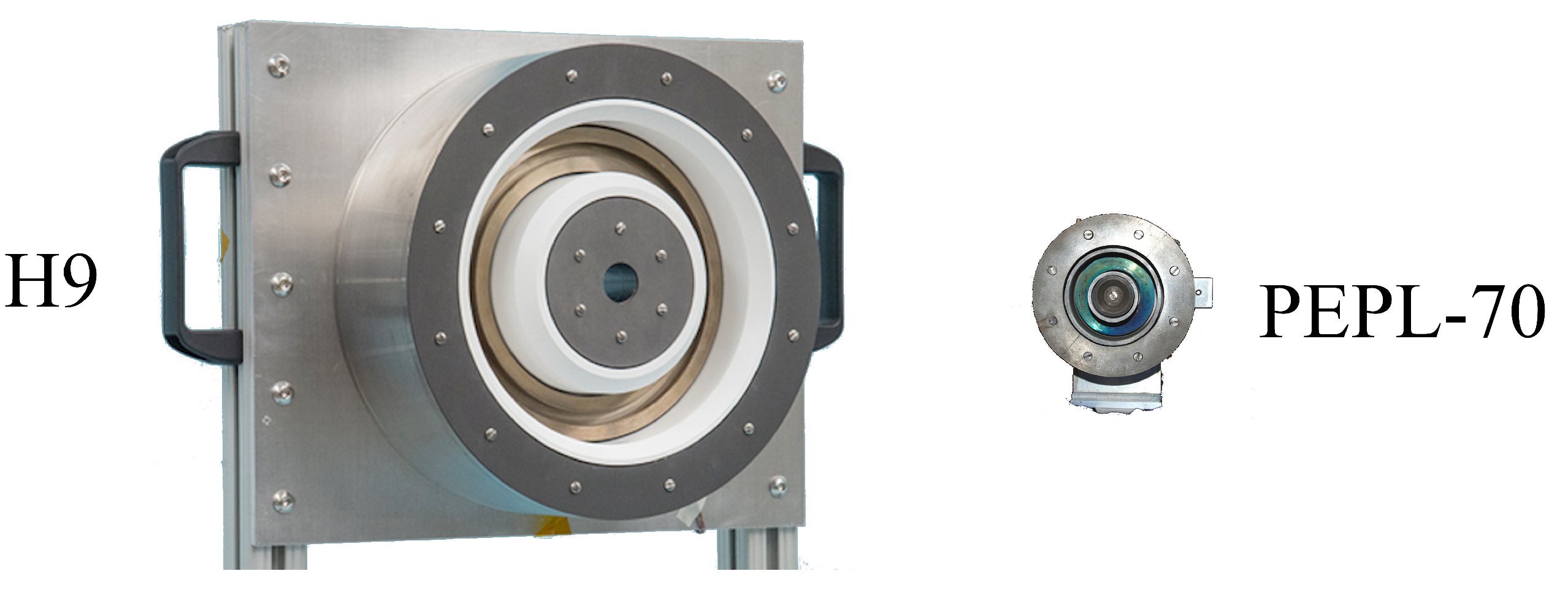
  55. Piragino, A.; Ferrato, E.; Faraji, F.; Reza, M.; Kitaeva, A.; Pedrini, D.; Andrenucci, M.; Andreussi, T. SITAEL’s Magnetically Shielded 20 kW Hall Thruster Tests. In Proceedings of the 36th International Electric Propulsion Conference, Vienna, Austria, 15–20 September 2019. [Google Scholar]
  56. Hall, S.J. Characterization of a 100-kW Class Nested-Channel Hall Thruster. Ph.D. Thesis, University of Michigan, Ann Arbor, MI, USA, 2017. [Google Scholar]
  57. Lev, D.; Myers, R.; Lemmer, K.; Kolbeck, J.; Keidar, M.; Koizumi, H.; Liang, H.; Yu, D.; Schönherr, T.; Gonzalez, J.; et al. The Technological and Commercial Expansion of Electric Propulsion in the Past 24 Years. In Proceedings of the 35th International Electric Propulsion Conference, Atlanta, GA, USA, 8–12 October 2017. [Google Scholar]
  58. Koppel, C.; Estublier, D. The Smart-1 Electric Propulsion Subsystem. In Proceedings of the 39th AIAA/ASME/SAE/ASEE Joint Propulsion Conference and Exhibit, Huntsville, AL, USA, 20–23 July 2003. [Google Scholar]
  59. Oh, D.Y.; Collins, S.; Goebel, D.; Hart, B.; Lantoine, G.; Snyder, S.; Whiffen, G.; Elkins-Tanton, L.; Lord, P.; Pirkl, Z.; et al. Development of the Psyche Mission for NASA’s Discovery Program. In Proceedings of the 35th International Electric Propulsion Conference, Atlanta, GA, USA, 8–12 October 2017. [Google Scholar]
  60. Randolph, T.; Kim, V.; Kaufman, H.; Kozubsky, K.; Zhurin, V.; Day, M. Facility effects on stationary plasma thruster testing. In Proceedings of the 23rd AIAA/AIDAA/DGLR/JSASS International Electric Propulsion Conference, Seattle, WA, USA, 13–16 September 1993. [Google Scholar]
  61. Low Earth Orbit Spacecraft Charging Design Handbook; Technical Report NASA-HDBK-4006; NASA: Washington, DC, USA, 2018.
  62. Diamant, K.; Spektor, R.; Beiting, E.; Young, J.; Curtiss, T. The Effects of Background Pressure on Hall Thruster Operation. In Proceedings of the 48th AIAA/ASME/SAE/ASEE Joint Propulsion Conference & Exhibit, Atlanta, GA, USA, 30 July–1 August 2012. [Google Scholar]
  63. Walker, M.L.R. Effects of Facility Backpressure on the Performance and Plume of a Hall Thruster. Ph.D. Thesis, University of Michigan, Ann Arbor, MI, USA, 2005. [Google Scholar]
  64. Frieman, J.D.; Walker, J.A.; Walker, M.L.R.; Khayms, V.; King, D.Q. Electrical Facility Effects on Hall Thruster Cathode Coupling: Performance and Plume Properties. J. Propuls. Power 2016, 32, 251–264. [Google Scholar] [CrossRef] [Green Version]
  65. Choueiri, E.Y. Plasma oscillations in Hall thrusters. Phys. Plasmas 2001, 8, 1411–1426. [Google Scholar] [CrossRef] [Green Version]
  66. Tilinin, G. High-frequency plasma waves in a Hall accelerator with an extended acceleration zone. Sov. Phys. Tech. Phys. 1977, 22, 974–978. [Google Scholar]
  67. Litvak, A.A.; Fisch, N.J. Resistive instabilities in Hall current plasma discharge. Phys. Plasmas 2001, 8, 648–651. [Google Scholar] [CrossRef] [Green Version]
  68. Barral, S.; Ahedo, E. Low-frequency model of breathing oscillations in Hall discharges. Phys. Rev. E 2009, 79. [Google Scholar] [CrossRef] [Green Version]
  69. Romadanov, I.; Smolyakov, A.; Raitses, Y.; Kaganovich, I.; Tian, T.; Ryzhkov, S. Structure of nonlocal gradient-drift instabilities in Hall ExB discharges. Phys. Plasmas 2016, 23, 122111. [Google Scholar] [CrossRef] [Green Version]
  70. Janhunen, S.; Smolyakov, A.; Chapurin, O.; Sydorenko, D.; Kaganovich, I.; Raitses, Y. Nonlinear structures and anomalous transport in partially magnetized ExB plasmas. Phys. Plasmas 2018, 25, 011608. [Google Scholar] [CrossRef]
  71. Fife, J.; Martinez-Sanchez, M.; Szabo, J. A numerical study of low-frequency discharge oscillations in Hall thrusters. In Proceedings of the 33rd AIAA/ASME/SAE/ASEE Joint Propulsion Conference & Exhibit, Seattle, WA, USA, 6–9 July 1997. [Google Scholar]
  72. Adam, J.C.; Héron, A.; Laval, G. Study of stationary plasma thrusters using two-dimensional fully kinetic simulations. Phys. Plasmas 2004, 11, 295–305. [Google Scholar] [CrossRef]
  73. Hara, K.; Sekerak, M.J.; Boyd, I.D.; Gallimore, A.D. Mode transition of a Hall thruster discharge plasma. J. Appl. Phys. 2014, 115. [Google Scholar] [CrossRef]
  74. Powis, A.T.; Carlsson, J.A.; Kaganovich, I.D.; Raitses, Y.; Smolyakov, A. Scaling of spoke rotation frequency within a Penning discharge. Phys. Plasmas 2018, 25, 072110. [Google Scholar] [CrossRef] [Green Version]
  75. Hara, K.; Mikellides, I.G. Characterization of low frequency ionization oscillations in Hall thrusters using a one-dimensional fluid model. In Proceedings of the 2018 Joint Propulsion Conference, Cincinnati, OH, USA, 9–11 July 2018. [Google Scholar]
  76. Dankanich, J.W.; Brophy, J.R.; Polk, J.E. Lifetime Qualification Standard for Electric Thrusters. In Proceedings of the 45th AIAA/ASME/SAE/ASEE Joint Propulsion Conference & Exhibit, Denver, CO, USA, 2–5 August 2009. [Google Scholar]
  77. Chien, K.R.; Hart, S.L.; Tighe, W.G.; De Pano, M.K.; Bond, T.A.; Spears, R. L-3 Communications ETI Electric Propulsion Overview. In Proceedings of the 29th International Electric Propulsion Conference, Princeton, NJ, USA, 31 October–4 November 2005. [Google Scholar]
  78. Brophy, J. The Dawn Ion Propulsion System. Space Sci. Rev. 2011, 163, 251–261. [Google Scholar] [CrossRef]
  79. Kuninaka, H. Microwave Discharge Ion Engines onboard Hayabusa Asteroid Explorer. AIP Conf. Proc. 2008, 997, 572–581. [Google Scholar]
  80. Randall, P.; Lewis, R.; Clark, S.; Chan, K.; Gray, H.; Steiger, C. BepiColombo—MEPS Commissioning Activities and T6 Ion Thruster Performance During Early Missions Operations. In Proceedings of the 36th International Electric Propulsion Conference, Vienna, Austria, 15–20 September 2019. [Google Scholar]
  81. Polk, J.; Anderson, J.; Brophy, J.; Rawlin, V.; Patterson, M.; Sovey, J.; Hamley, J. An overview of the results from an 8200 hour wear test of the NSTAR ion thruster. In Proceedings of the 35th Joint Propulsion Conference and Exhibit, Los Angeles, CA, USA, 20–24 June 1999. [Google Scholar]
  82. Shastry, R.; Herman, D.A.; Soulas, G.C.; Patterson, M.J. End-of-test Performance and Wear Characterization of NASA’s Evolutionary Xenon Thruster (NEXT) Long-Duration Test. In Proceedings of the 50th AIAA/ASME/SAE/ASEE Joint Propulsion Conference, Cleveland, OH, USA, 28–30 July 2014. [Google Scholar]
  83. Nakano, M. Three-dimensional simulations of grid erosion in ion engines. Vacuum 2008, 83, 82–85. [Google Scholar] [CrossRef]
  84. Herman, D.; Gallimore, A. Discharge Chamber Plasma Potential Mapping of a 40-cm NEXT-type Ion Engine. In Proceedings of the 41st AIAA/ASME/SAE/ASEE Joint Propulsion Conference & Exhibit, Tucson, AZ, USA, 10–13 July 2005. [Google Scholar]
  85. Herman, D.; Soulas, G.; Patterson, M. Status of the NEXT Long-Duration Test After 23,300 Hours of Operation. In Proceedings of the 45th AIAA/ASME/SAE/ASEE Joint Propulsion Conference & Exhibit, Denver, CO, USA, 2–5 August 2009. [Google Scholar]
  86. Mikellides, I.G.; Katz, I.; Goebel, D.M.; Jameson, K.K.; Polk, J.E. Wear Mechanisms in Electron Sources for Ion Propulsion, II: Discharge Hollow Cathode. J. Propuls. Power 2008, 24, 866–879. [Google Scholar] [CrossRef]
  87. Mikellides, I.G.; Katz, I. Wear Mechanisms in Electron Sources for Ion Propulsion, I: Neutralizer Hollow Cathode. J. Propuls. Power 2008, 24, 855–865. [Google Scholar] [CrossRef]
  88. Kornfeld, G.D.; Koch, N.; Harmann, H.P. Physics and Evolution of HEMP-Thrusters. In Proceedings of the 30th International Electric Propulsion Conference, Florence, Italy, 17–20 September 2007. [Google Scholar]
  89. Lazurenko, A.; Genovese, A.; Stalzer, H.; Heidemann, R.; Weis, S.; Holtmann, P.; Wolf, T.; Puttmann, N. Progress in Lifetime Test of HEMP-T Electric Propulsion System. In Proceedings of the 35th International Electric Propulsion Conference, Atlanta, GA, USA, 8–12 October 2017. [Google Scholar]
  90. Liu, H.; Zeng, M.; Yu, D.; Huang, H. Study of channel length effect on low power HEMP Thruster. Vacuum 2019, 163, 328–337. [Google Scholar] [CrossRef]
  91. Dailey, C.; Lovberg, R. Large diameter inductive plasma thrusters. In Proceedings of the 14th International Electric Propulsion Conference, Princeton, NJ, USA, 30 October–1 November 1979. [Google Scholar]
  92. Lovberg, R.H.; Dailey, C.L. Large Inductive Thruster Performance Measurement. AIAA J. 1982, 20, 971–977. [Google Scholar] [CrossRef]
  93. Dailey, C.; Lovberg, R.H. The PIT MkV Pulsed Inductive Thruster; Contractor Report 191155; NASA: Washington, DC, USA; Lewis Research Center: Cleveland, OH, USA, 1993.
  94. Polzin, K.; Rose, M.; Miller, R.; Best, S.; Owens, T.; Dankanich, J. Design of a Low-Energy FARAD Thruster. In Proceedings of the 43rd AIAA/ASME/SAE/ASEE Joint Propulsion Conference & Exhibit, Cincinnati, OH, USA, 8–11 July 2007. [Google Scholar]
  95. Polzin, K.A.; Martin, A.K.; Eskridge, R.H.; Kimberlin, A.C.; Addona, B.M.; Devineni, A.P.; Dugal-Whitehead, N.R.; Hallock, A.K. Summary of the 2012 Inductive Pulsed Plasma Thruster Development and Testing Program; Technical Report NASA/TP-2013-217488; Marshal Space Flight Center: Huntsville, AL, USA, 2013.
  96. Blevin, H.A.; Thonemann, P.C. Plasma Confinement Using an Alternating Magnetic Field; Culham Lab.: Abingdon, Berks, UK, 1962. [Google Scholar]
  97. Kirtley, D.; Gallimore, D.A.D.; Haas, D.J.; Reilly, M. High Density Magnetized Toroid Formation and Translation within XOCOT: An Annular Field Reversed Configuration Plasma Concept. In Proceedings of the 30th International Electric Propulsion Conference, Florence, Italy, 17–20 September 2007. [Google Scholar]
  98. Hill, C.S. Preliminary Results on an Annular Field ReversedConfiguration Translation Experiment. In Proceedings of the 32nd International Electric Propulsion Conference, Wiesbaden, Germany, 11–15 September 2011. [Google Scholar]
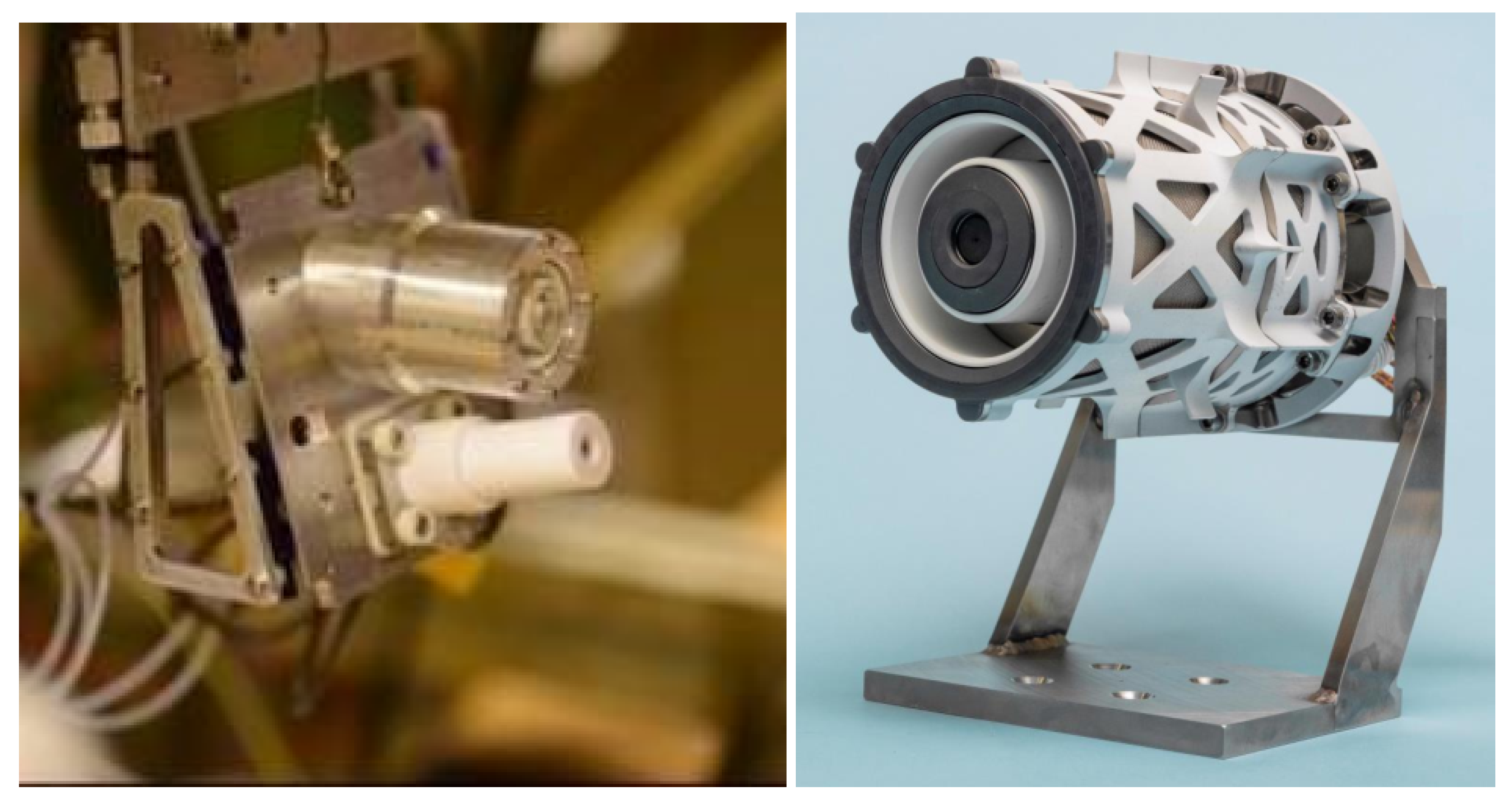
  99. Weber, T.E.; Slough, J.T.; Kirtley, D. The electrodeless Lorentz force (ELF) thruster experimental facility. Rev. Sci. Instrum. 2012, 83, 113509. [Google Scholar] [CrossRef] [PubMed]
  100. Niemala, C.S.; King, L.B. Numerical Optimization of an Annular Field ReversedConfiguration Translation Experiment. In Proceedings of the 31st International Electric Propulsion Conference, Ann Arbor, MI, USA, 20–24 September 2009. [Google Scholar]
  101. Woods, J.M.; Jorns, B.A.; Gallimore, A.D. Circuit Modeling of Rotating Magnetic Field Field-reversed Configuration Thrusters. In Proceedings of the 54th AIAA/SAE/ASEE Joint Propulsion Conference, Cincinnati, OH, USA, 9–11 July 2018. [Google Scholar]
  102. Polzin, K.A. Scaling and Systems Considerations in Pulsed Inductive Thrusters. In Proceedings of the 30th International Electric Propulsion Conference, Florence, Italy, 17–20 September 2007. [Google Scholar]
  103. Hofer, R.R.; Randolph, T.M. Mass and Cost Model for Selecting Thruster Size in Electric Propulsion Systems. J. Propuls. Power 2012, 29, 166–177. [Google Scholar] [CrossRef]
  104. Dankanich, J.; Vondra, B.; Ilin, A. Fast Transits to Mars Using Electric Propulsion. In Proceedings of the 46th AIAA/ASME/SAE/ASEE Joint Propulsion Conference & Exhibit, Nashville, TN, USA, 25–28 July 2010. [Google Scholar]
  105. Spores, R.; Monheiser, J.; Dempsey, B.P.; Wade, D.; Creel, K.; Jacobson, D.; Drummond, G. A Solar Electric Propulsion Cargo Vehicle To Support NASA Lunar Exploration Program. In Proceedings of the 29th International Electric Propulsion Conference, Princeton, NJ, USA, 31 October–4 November 2005. [Google Scholar]
  106. Beal, B.; Gallimore, A.; Hargus, W. The Effects of Cathode Configuration on Hall Thruster Cluster Plume Properties. In Proceedings of the 41st AIAA/ASME/SAE/ASEE Joint Propulsion Conference & Exhibit, Tucson, AZ, USA, 10–13 July 2005. [Google Scholar]
  107. Beal, B.E.; Gallimore, A.D.; Haas, J.M.; Hargus, W.A. Plasma Properties in the Plume of a Hall Thruster Cluster. J. Propuls. Power 2004, 20, 985–991. [Google Scholar] [CrossRef] [Green Version]
  108. Jackson, J.; Cassady, J.; Allen, M.; Myers, R.; Tofil, T.; Herman, D.; Pencil, E. Development Of High Power Hall Thruster Systems To Enable The NASA Exploration Vision; Space Propulsion 2018; NASA: Washington, DC, USA, 2018.
  109. Liang, R. The Combination of Two Concentric Discharge Channels into a Nested Hall-Effect Thruster. Ph.D. Thesis, University of Michigan, Ann Arbor, MI, USA, 2013. [Google Scholar]
  110. Cusson, S.; Jorns, B.; Gallimore, A. Impact of Neutral Density on the Magnetic Shielding of Hall Thrusters. In Proceedings of the 36th International Electric Propulsion Conference, Vienna, Austria, 15–20 September 2019. [Google Scholar]
  111. Hall, S.J.; Jorns, B.; Gallimore, A.; Hofer, R.R. Expanded Thruster Mass Model Incorporating Nested Hall Thrusters. In Proceedings of the 53rd AIAA/SAE/ASEE Joint Propulsion Conference, Atlanta, GA, USA, 10–12 July 2017. [Google Scholar]
  112. Su, L.L.; Hall, S.J.; Cusson, S.E.; Jorns, B.A. Model for the Increase in Thruster Efficiency from Cross-Channel Coupling in Nested Hall Thrusters. In Proceedings of the 36th International Electric Propulsion Conference, Vienna, Austria, 15–20 September 2019. [Google Scholar]
  113. Nakanishi, S.; Pawlik, E.V. Experimental investigation of a 1.5-m-diam Kaufman thruster. J. Spacecr. Rocket. 1968, 5, 801–807. [Google Scholar] [CrossRef]
  114. Brophy, J.R. NASA’s Deep Space 1 ion engine (plenary). Rev. Sci. Instrum. 2002, 73, 1071–1078. [Google Scholar] [CrossRef]
  115. Schmidt, G.; Jacobson, D.; Patterson, M.; Ganapathi, G.; Brophy, J.; Hofer, R. Electric Propulsion Research and Development at NASA; Space Propulsion 2018; NASA: Washington, DC, USA, 2018.
  116. Foster, J.E.; Haag, T.; Kamhawi, H.; Patterson, M.; Malone, S.; Elliot, F.; Williams, G.; Sovey, J.; Carpenter, C. The High Power Electric Propulsion (HiPEP) Ion Thruster. In Proceedings of the 40th AIAA/ASME/SAE/ASEE Joint Propulsion Conferenceand Exhibit, Fort Lauderdale, FL, USA, 11–14 July 2004. [Google Scholar]
  117. Sovey, J.; Mantenieks, M. Performance and lifetime assessment of magnetoplasmadynamic arc thruster technology. J. Propuls. Power 1991, 7. [Google Scholar] [CrossRef]
  118. Herdrich, G.; Bauder, U.; Bock, D.; Eichhorn, C.; Haag, D.; Lau, M.; Schönherr, T.; Stindl, T.; Fertig, M.; Löhle, S.; et al. Activities in Electric Propulsion Development at IRS. Trans. Jpn. Soc. Aeronaut. Space Sci. Space Technol. Jpn. 2009, 7. [Google Scholar] [CrossRef]
  119. Toki, K.; Shimizu, Y.; Kuriki, K. Application of MPD thruster systems to interplanetary missions. J. Propuls. Power 1986, 2, 508–512. [Google Scholar] [CrossRef]
  120. Malliaris, A.C.; John, R.R.; Garrison, R.L.; Libby, D.R. Performance of Quasi-Steady MPD Thrusters at High Powers. AIAA J. 1972, 10, 121–122. [Google Scholar] [CrossRef]
  121. Gorshkov, O.; Shutov, V.; Kozubsky, K.; Ostrovsky, V.; Obukhov, V. Development of High Power Magnetoplasmadynamic Thrusters in the USSR. In Proceedings of the 30th International Electric Propulsion Conference, Florence, Italy, 17–20 September 2007. [Google Scholar]
  122. Takegahara, H.; Kuninaka, H.; Funaki, I.; Ando, A.; Koizumi, H.; Schönherr, T.; Shinohara, S.; Tanikawa, T.; Nakano, M.; Nakayama, Y.; et al. Overview of Electric Propulsion Research Activities in Japan. In Proceedings of the 32nd International Electric Propulsion Conference, Wiesbaden, Germany, 11–15 September 2015. [Google Scholar]
  123. Boxberger, A.; Behnke, A.; Herdrich, G. Current Advances in Optimization of Operative Regimes of Steady State Applied Field MPD Thrusters. In Proceedings of the 36th International Electric Propulsion Conference, Vienna, Austria, 15–20 September 2019. [Google Scholar]
  124. LaPointe, M.; Strzempkowski, E.; Pencil, E. High Power MPD Thruster Performance Measurements. In Proceedings of the 40th AIAA/ASME/SAE/ASEE Joint Propulsion Conference and Exhibit, Fort Lauderdale, FL, USA, 11–14 July 2004. [Google Scholar]
  125. Herdrich, G.; Binder, T.; Boxberger, A.; Chan, Y.A.; Ehresmann, M.; Harmansa, N.; Montag, C.; Romano, F.; Skalden, J.; Fasoulas, S.; et al. Research and Development on Electric and Advanced Propulsion at IRS. In Proceedings of the 35th International Electric Propulsion Conference, Atlanta, GA, USA, 8–12 October 2017. [Google Scholar]
  126. Lev, D.R.; Choueiri, E.Y. Scaling of Efficiency with Applied Magnetic Field in Magnetoplasmadynamic Thrusters. J. Propuls. Power 2012, 28, 609–616. [Google Scholar] [CrossRef]
  127. Dankanich, J.; Lozano, P. Dual Mode Green Propulsion for Revolutionary Performance Gains with Minimal Recurring Investments; Planetary Science Vision 2050 Workshop: Washington, DC, USA, 2017. [Google Scholar]
  128. Díaz, F.R. The Vasimr Rocket. Sci. Am. 2000, 283, 90–97. [Google Scholar] [CrossRef]
  129. Squire, J.P.; Carter, M.; Diaz, F.C.; Corrigan, A.; Dean, L.; Farrias, J.; Giambusso, M.; McCaskill, G.; Yao, T. Run-time Accumulation Testing of the 100 kW VASIMR VX-200SS Device. In Proceedings of the 2018 Joint Propulsion Conference, Cincinnati, OH, USA, 9–11 July 2018. [Google Scholar]
  130. Sercel, J.C. An Experimental and Theoretical Study of the ECR Plasma Engine. Ph.D. Thesis, California Institute of Technology, Pasadena, CA, USA, 1993. [Google Scholar]
  131. Cassady, L.; Longmier, B.; Olsen, C.; Ballenger, M.; McCaskill, G.; Illin, A.; Carter, M.; Glover, T.; Squire, J.; Chang Diaz, F.; et al. VASIMR Performance Results. In Proceedings of the 46th AIAA/ASME/SAE/ASEE Joint Propulsion Conference& Exhibit, Nashville, TN, USA, 25–28 July 2010. [Google Scholar]
  132. Corrigan, A.; Carter, M.; Squire, J.; Chang Diaz, F.; Dean, L.; Giambusso, M.; McCaskill, G.; Farrias, J.; Yao, T. Enhancing VASIMR with Maturing Technologies. In Proceedings of the 2018 Joint Propulsion Conference, Cincinnati, OH, USA, 9–11 July 2018. [Google Scholar]
  133. Robbins, W.; Finger, H. An historical perspective of the NERVA nuclear rocket engine technology program. In Proceedings of the Conference on Advanced SEI Technologies, Cleveland, OH, USA, 4–6 September 1991. [Google Scholar]
  134. Hofer, R.R.; Anderson, J.R. Finite Pressure Effects in Magnetically Shielded Hall Thrusters. In Proceedings of the 50th AIAA/ASME/SAE/ASEE Joint Propulsion Conference, Cleveland, OH, USA, 28–30 July 2014. [Google Scholar]
  135. de Grys, K.; Tilley, D.; Aadland, R. BPT Hall thruster plume characteristics. In Proceedings of the 35th Joint Propulsion Conference and Exhibit, Los Angeles, CA, USA, 20–24 June 1999. [Google Scholar]
  136. Hofer, R.; Peterson, P.; Gallimore, A. Characterizing Vacuum Facility Backpressure Effects on the Performance of a Hall Thruster. In Proceedings of the 27th International Electric Propulsion Conference, Pasadena, CA, USA, 15–19 October 2001; p. 10. [Google Scholar]
  137. Brown, D.L.; Gallimore, A.D. Evaluation of Facility Effects on Ion Migration in a Hall Thruster Plume. J. Propuls. Power 2011, 27, 573–585. [Google Scholar] [CrossRef]
  138. Huang, W.; Kamhawi, H.; Lobbia, R.B.; Brown, D.L. Effect of Background Pressure on the Plasma Oscillation Characteristics of the HiVHAc Hall Thruster. In Proceedings of the 50th AIAA/ASME/SAE/ASEE Joint Propulsion Conference, Cleveland, OH, USA, 28–30 July 2014. [Google Scholar]
  139. Diamant, K.D.; Liang, R.; Corey, R.L. The Effect of Background Pressure on SPT-100 Hall Thruster Performance. In Proceedings of the 50th AIAA/ASME/SAE/ASEE Joint Propulsion Conference, Cleveland, OH, USA, 28–30 July 2014. [Google Scholar]
  140. Huang, W.; Kamhawi, H.; Haag, T. Plasma Oscillation Characterization of NASA’s HERMeS Hall Thruster via High Speed Imaging. In Proceedings of the 52nd AIAA/SAE/ASEE Joint Propulsion Conference, Salt Lake City, UT, USA, 25–27 July 2016. [Google Scholar]
  141. Tighe, W.G.; Spektor, R.; Diamant, K.D.; Kamhawi, H. Effects of Background Pressure on the NASA 173M Hall Current Thruster Performance. In Proceedings of the 34th International Electric Propulsion Conference, Kobe, Japan, 7–10 July 2015. [Google Scholar]
  142. Cusson, S.; Hofer, R.; Lobbia, R.; Jorns, B.; Gallimore, A. Performance of the H9 Magnetically Shielded Hall Thrusters. In Proceedings of the 35th International Electric Propulsion Conference, Atlanta, GA, USA, 8–12 October 2017. [Google Scholar]
  143. Byrne, M.P.; Jorns, B.A. Data-driven Models for the Effects of BackgroundPressure on the Operation of Hall Thrusters. In Proceedings of the 36th International Electric Propulsion Conference, Vienna, Austria, 15–20 September 2019. [Google Scholar]
  144. Mikellides, I.G.; Ortega, A.L.; Chaplin, V.H.; Snyder, J.S. Facility pressure effects on a Hall thruster with an external cathode, II: Theoretical model of the thrust and the significance of azimuthal asymmetries in the cathode plasma. Plasma Sources Sci. Technol. 2020, 29, 035010. [Google Scholar] [CrossRef]
  145. Van Noord, J.; Herman, D. Application of the NEXT Ion Thruster Lifetime Assessment to Thruster Throttling. In Proceedings of the 44th AIAA/ASME/SAE/ASEE Joint Propulsion Conference & Exhibit, Hartford, CT, USA, 21–23 July 2008. [Google Scholar]
  146. Wachs, B.; Jorns, B. Real-Time Optimization of an Electron Cyclotron Resonance Thruster. In Proceedings of the 2020 AIAA Propulsion and Energy Forum, New Orleans, LA, USA, 24–26 August 2020. [Google Scholar]
  147. Snyder, J.; Brophy, J.; Hofer, R.; Goebel, D.; Katz, I. Experimental Investigation of a Direct-Drive Hall Thruster and Solar Array System at Power Levels up to 10 kW. In Proceedings of the 48th AIAA/ASME/SAE/ASEE Joint Propulsion Conference & Exhibit, Atlanta, GA, USA, 30 July–1 August 2012. [Google Scholar]
  148. Brophy, J.R.; Polk, J.E.; Goebel, D.M. Development of a 50,000-s, Lithium-fueled, Gridded Ion Thruster. In Proceedings of the 35th International Electric Propulsion Conference, Atlanta, GA, USA, 8–12 October 2017. [Google Scholar]
  149. Massey, D.; King, L.; Makela, J. Development of a Direct Evaporation Bismuth Hall Thruster. In Proceedings of the 44th AIAA/ASME/SAE/ASEE Joint Propulsion Conference & Exhibit, Hartford, CT, USA, 21–23 July 2008. [Google Scholar]
  150. Kamhawi, H.; Haag, T.; Benavides, G.; Hickman, T.; Smith, T.; Williams, G.; Myers, J.L.; Polzin, K.A.; Dankanich, J.; Byrne, L.; et al. Overview of Iodine Propellant Hall Thruster Development Activities at NASA Glenn Research Center. In Proceedings of the 52nd AIAA/SAE/ASEE Joint Propulsion Conference, Salt Lake City, UT, USA, 25–27 July 2016. [Google Scholar]
  151. Sovey, J.S.; Rawlin, V.K.; Patterson, M.J. Ion Propulsion Development Projects in U.S.: Space Electric Rocket Test I to Deep Space 1. J. Propuls. Power 2001, 17, 517–526. [Google Scholar] [CrossRef]
  152. Gibson, M.A.; Oleson, S.R.; Poston, D.I.; McClure, P. NASA’s Kilopower reactor development and the path to higher power missions. In Proceedings of the 2017 IEEE Aerospace Conference, Big Sky, MT, USA, 4–11 March 2017; pp. 1–14. [Google Scholar]
  153. Stella, P.M.; DiStefano, S.; Rayman, M.D.; Ulloa-Severino, A. Early mission power assessment of the Dawn solar array. In Proceedings of the 2009 34th IEEE Photovoltaic Specialists Conference (PVSC), Philadelphia, PA, USA, 7–12 June 2009; pp. 001617–001621. [Google Scholar]
  154. Goddard, R.H.; Robert, H. Goddard: An autobiography. Astronautics 1959, 4, 24. [Google Scholar]
  155. Nishiyama, K.; Hosoda, S.; Ueno, K.; Kuninaka, H. The Ion Engine System for Hayabusa2. In Proceedings of the 32nd International Electric Propulsion Conference, Wiesbaden, Germany, 11–15 September 2011. [Google Scholar]
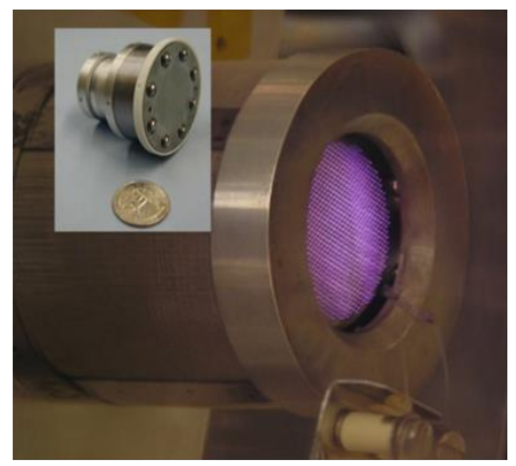
Figure 1. The three major types of acceleration schemes for electric propulsion in terms of thrust per power and specific impulse.
Aerospace 07 00120 g001
Figure 2. The typical development of research activity for electric propulsion systems, transitioning from theoretical research to flight. The cumulative research activity reflects the maturity of the technology.
Aerospace 07 00120 g002
Figure 3. Notional s-curves for various low-power electric propulsion technologies categorized with the color scheme of Figure 1. Shown are: RJ, resistojet; HET, Hall effect thruster; PPT, pulsed plasma thruster; GIT, gridded ion thruster; ES, electrospray; and RF,MN, radio frequency power paired with a magnetic nozzle.
Aerospace 07 00120 g003
Figure 4. The PEPL-70 (right), a low-power Hall thruster developed at the University of Michigan in the 1990s, compared to the H9 (left), a state-of-the-art Hall thruster developed from 2015–2017, roughly to scale.
Aerospace 07 00120 g004
Figure 5. A 50 W Hall thruster, part of Exotrail’s ExoMG-nano propulsion platform (left); reproduced from [12], courtesy of Dr. Antonio Gurciullo, Exotrail. An engineering model of the Magnetically-Shielded Miniature (MaSMi) Hall thruster for the ASTRAEUS program (right); reproduced from [14], courtesy of Dr. Ryan Conversano, JPL.
Aerospace 07 00120 g005
Figure 6. The Miniature Xenon Ion (MiXI) gridded ion thruster; reproduced from [26] courtesy of the Wirz research group, UCLA.
Aerospace 07 00120 g006
Figure 7. A coaxial microwave thruster designed and tested at the University of Michigan based on a similar device designed at ONERA [36].
Aerospace 07 00120 g007
Figure 8. Notional s-curves for various moderate-power electric propulsion technologies categorized with the color scheme of Figure 1, and additionally including arcjets (AJ) and pulsed inductive thrusters (PIT).
Aerospace 07 00120 g008
Figure 9. The H9 (left), a 9 kW magnetically-shielded Hall thruster, and the H6 (right), a 6 kW unshielded Hall thruster. Both were developed by the Jet Propulsion Laboratory, the Air Force Research Laboratory, and the University of Michigan.
Aerospace 07 00120 g009
Figure 10. The HT20k DM1 magnetically-shielded Hall thruster developed by SITAEL, before first firing (left) and operating at 400 V, 20 kW (right); reproduced from [55] courtesy of Mr. Antonio Piragino, SITAEL.
Aerospace 07 00120 g010
Figure 11. A laboratory model of the NASA Evolutionary Xenon Thruster (NEXT) gridded ion thruster (left), tested at the University of Michigan [84]. The T6 ion thruster used on the BepiColombo mission (right); reproduced with permission of QinetiQ.
Aerospace 07 00120 g011
Figure 12. A rotating magnetic field thruster developed at the University of Michigan, here mounted on a thrust stand for performance testing.
Aerospace 07 00120 g012
Figure 13. Notional s-curves for various low-power electric propulsion technologies categorized with the color scheme of Figure 1, including magnetoplasmadynamic thrusters (MPD) and nuclear thermal propulsion (NT).
Aerospace 07 00120 g013
Figure 14. The X2, X3, and N30 nested Hall thrusters.
Aerospace 07 00120 g014
Figure 15. The discharge chamber of the HiPEP ion thruster developed for the nuclear-powered Jupiter Icy Moons Orbiter.
Aerospace 07 00120 g015
Figure 16. The Institute of Space Systems (IRS) SX3 thruster, operating at 100 kW, 690 A, 400 mT, and 120 mg/s argon flow; reproduced from [125] courtesy of Dr. Georg Herdrich, IRS.
Aerospace 07 00120 g016
Figure 17. Phenomenological thrust values as a function of pressure compared to on-orbit data from the Russian Express missions, repeated from [143].
Aerospace 07 00120 g017
Figure 18. A notional machine-learning process to estimate electron transport given experimental plasma information based on a set of training data.
Aerospace 07 00120 g018
Figure 19. An example of data-driven optimization of an ECR thruster from [146], in this case with the purpose of maximizing the plume floating potential. Multiple trials are conducted according to a data-driven optimization algorithm (right), leading to a map of floating potentials (left) with a peak identified when frequencies are identically 1650 MHz.
Aerospace 07 00120 g019
Figure 20. The solar irradiance as a function of distance in the Solar system, with Earth, Jupiter, Uranus, and Pluto noted. For comparison, the solar energy throughput of the Dawn spacecraft at 1 AU [153], the International Space Station, and a common pocket calculator are shown.
Aerospace 07 00120 g020